WO2024228247A1 - Faisceau de câbles, système d'identification de faisceau et dispositif embarqué - Google Patents
Faisceau de câbles, système d'identification de faisceau et dispositif embarqué Download PDFInfo
- Publication number
- WO2024228247A1 WO2024228247A1 PCT/JP2023/017100 JP2023017100W WO2024228247A1 WO 2024228247 A1 WO2024228247 A1 WO 2024228247A1 JP 2023017100 W JP2023017100 W JP 2023017100W WO 2024228247 A1 WO2024228247 A1 WO 2024228247A1
- Authority
- WO
- WIPO (PCT)
- Prior art keywords
- wire harness
- transmission line
- filter
- communication
- unit
- Prior art date
- Legal status (The legal status is an assumption and is not a legal conclusion. Google has not performed a legal analysis and makes no representation as to the accuracy of the status listed.)
- Ceased
Links
Images









Classifications
-
- H—ELECTRICITY
- H01—ELECTRIC ELEMENTS
- H01B—CABLES; CONDUCTORS; INSULATORS; SELECTION OF MATERIALS FOR THEIR CONDUCTIVE, INSULATING OR DIELECTRIC PROPERTIES
- H01B7/00—Insulated conductors or cables characterised by their form
Definitions
- This disclosure relates to a wire harness, a harness identification system, and an in-vehicle device.
- Vehicles are equipped with various on-board devices.
- the on-board devices include various ECUs (Electronic Control Units) that manage functions necessary for the vehicle, such as steering and braking. These ECUs are connected to each other to form a network. Each ECU communicates with each other via this network to realize the basic functions of the vehicle, such as "running,” “turning,” and “stopping.” Wire harnesses are usually used to connect on-board devices.
- ECUs Electronic Control Units
- Wire harnesses are usually used to connect on-board devices.
- Patent Document 1 proposes a connector system for preventing communication between a wire harness and unintended devices.
- the connector system described in Patent Document 1 includes a first connector and a second connector connected thereto.
- the second connector includes a processing unit that performs processing to create verification information and transmit it to the first connector.
- the first connector includes a verification unit that verifies the second connector based on the verification information received from the second connector. If the verification unit cannot receive the verification information, it determines that the verification has failed.
- the first connector further includes a switch that, when connected to the second connector, switches whether or not to electrically connect the transmission line in the first connector to the transmission line in the second connector, and a control unit that controls the switch based on the verification results of the verification unit.
- the verification unit of the first connector determines that verification has failed.
- the control unit of the first connector keeps the switch in the off state. This cuts off the electrical connection between the transmission line of the first connector and the transmission line of the second connector. Since communication between the wire harness and unintended devices can be prevented, security of communication between devices can be ensured.
- a wire harness is a wire harness that connects communication between a first communication unit and a second communication unit, and includes a transmission line that is provided between the first communication unit and the second communication unit and transmits a signal from at least one of the first communication unit and the second communication unit, and a filter unit that is provided at a predetermined position on the transmission line and has predetermined characteristics.
- the present disclosure can be realized not only as a wire harness, harness identification system, or in-vehicle device including such a characteristic configuration, but also as a recording medium having recorded thereon a program for causing a computer to execute the characteristic steps executed by the in-vehicle device or harness identification system. Furthermore, the present disclosure can also be realized as other systems or devices including a wire harness, harness identification system, or in-vehicle device.
- FIG. 1 is a diagram illustrating an example of the configuration of a system according to a first embodiment.
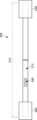
- FIG. 2 is a diagram for explaining a configuration example of the wire harness shown in FIG.
- FIG. 3A is a diagram for explaining an example of a filter portion provided in the wire harness shown in FIG. 1, and also shows an example of an open stub constituting the filter portion.
- FIG. 3B is a diagram for explaining an example of a filter portion provided in the wire harness shown in FIG. 1, and also a diagram showing an example of frequency characteristics of an open stub.
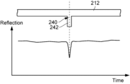
- FIG. 4 is a diagram for explaining the characteristics of the filter portion provided in the wire harness shown in FIG.
- FIG. 5 is a diagram illustrating an example of the configuration of the in-vehicle device illustrated in FIG. FIG.
- FIG. 6 is a block diagram showing an example of the configuration of the identification device shown in FIG.
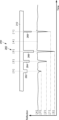
- FIG. 7 is a diagram illustrating an example of characteristics of a filter portion in the wire harness according to the second embodiment.
- FIG. 8 is a diagram for explaining a configuration example of the wire harness according to the third embodiment.
- FIG. 9A is a diagram for explaining a filter portion provided in the wire harness shown in FIG. 8, and is also a diagram showing an example of a filter exhibiting capacitive reflection characteristics.
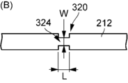
- FIG. 9B is a diagram for explaining a filter portion provided in the wire harness shown in FIG. 8, and is also a diagram showing an example of a filter exhibiting inductive reflection characteristics.
- FIG. 10 is a diagram illustrating an example of characteristics of a filter portion in the wire harness according to the third embodiment.
- FIG. 9A is a diagram for explaining a filter portion provided in the wire harness shown in FIG. 8, and is also a diagram showing an example of a filter exhibiting capacitive reflection characteristics.
- FIG. 9B is
- FIG. 11 is a diagram for explaining a configuration example of the wire harness according to the fourth embodiment.
- FIG. 12 is a diagram for explaining a configuration example of the wire harness according to the fifth embodiment.
- FIG. 13 is a diagram for explaining the characteristics of the filter portion provided in the wire harness shown in FIG.
- FIG. 14 is a diagram illustrating an example of a configuration of an in-vehicle device according to the sixth embodiment.
- Patent Document 1 The connector system described in Patent Document 1 is an excellent system in terms of ensuring security.
- the processing unit, verification unit, and control unit are realized by electronic devices, and the electronic devices and switches are built into the connector, it is difficult to simplify the configuration. Therefore, the manufacturing cost tends to be high.
- This disclosure has been made to solve the problems described above, and one objective of this disclosure is to provide a wire harness, harness identification system, and in-vehicle device that contribute to improving communication security with a simple configuration.
- a wire harness is a wire harness that connects communication between a first communication unit and a second communication unit, and includes a transmission line that is provided between the first communication unit and the second communication unit and transmits a signal from at least one of the first communication unit and the second communication unit, and a filter unit that is provided at a predetermined position on the transmission line and has predetermined characteristics.
- a filter unit having a predetermined characteristic is provided at a predetermined position of the transmission line. For example, if a diagnostic signal is transmitted to the transmission line, a signal corresponding to the characteristics of the filter unit is generated. On the other hand, such a signal is not generated in a wire harness that does not have a filter unit. Therefore, it is possible to determine whether the connected wire harness is a genuine wire harness or not based on whether the reflected waveform of the diagnostic signal includes a signal corresponding to the characteristics of the filter unit. In other words, it is possible to determine the authenticity of the connected wire harness. This makes it possible to detect that a genuine wire harness is not connected (that an unauthorized wire harness is connected).
- the wire harness disclosed herein can contribute to improving communication security with a simple configuration.
- the filter unit may be configured to filter out-of-band signals, which are bands outside the communication band used for communication between the first communication unit and the second communication unit. This allows the filter unit to be provided on the transmission line for communication, making the configuration simpler.
- the transmission line may include a line that is not used for communication between the first communication unit and the second communication unit.
- a transmission line for identifying whether or not the wire harness is genuine is provided in addition to the transmission line for communication. This allows the characteristics of the filter unit to be set without being limited by the communication band, thereby increasing the degree of freedom in design.
- the filter section may include an open stub having a predetermined length, and the predetermined characteristic may include a capacitive reflection characteristic. This makes it easy to form a filter section having the predetermined characteristic.
- the filter section may include a plurality of open stubs having a predetermined length, and the plurality of open stubs may be provided at predetermined positions on the transmission line. This allows the authenticity of the wire harness to be determined based on a plurality of signals, thereby improving the accuracy of the determination.
- the open stubs may be configured to have different lengths. This allows the pattern of the multiple signals to be changed, making it easy to change the detection pattern for authenticity determination.
- the filter section may be configured to have predetermined characteristics by varying the line width of the transmission line. This makes it easier to form the filter section, and therefore makes it easier to reduce manufacturing costs.
- the filter section may be configured to include a filter region having inductive reflection characteristics or a filter region having capacitive reflection characteristics.
- the filter region having inductive reflection characteristics can be formed, for example, by making the line width of the transmission line smaller than the line width of the transmission line in a region other than the region in which the filter section is provided. This makes it possible to easily obtain a wire harness that contributes to improving communication security with a simple configuration.
- the filter section includes a filter region with capacitive reflection characteristics
- the filter region with capacitive reflection characteristics can be formed, for example, by making the line width of the transmission line larger than the line width of the transmission line in areas other than the area in which the filter section is provided. Therefore, this also makes it possible to easily obtain a wire harness that contributes to improving communication security with a simple configuration.
- the filter unit may be configured to include a plurality of filters with different reflection characteristics. This makes it possible to detect with a simple configuration that a genuine wire harness is not connected (that an unauthorized wire harness is connected).
- the filter unit may be configured to be provided at a predetermined position on the transmission line. This allows the authenticity of the wire harness to be determined based on information on the position at which the filter unit is provided.
- the wire harness may further include a connector provided at an end of the transmission line, and the filter portion may be configured to be located inside the connector. This can reduce the difference in appearance due to the presence or absence of the filter portion. In other words, it can be made difficult to tell from the outside that a filter portion is provided.
- the wire harness may further include a sheet-like holding member that holds the transmission line. This makes it easier to form a filter section with predetermined characteristics.
- a harness identification system includes a wire harness and an identification device that identifies whether the wire harness is genuine.
- the wire harness includes a transmission line that transmits a signal, and a filter unit that is provided at a predetermined position on the transmission line and has predetermined characteristics.
- the identification device includes a signal transmitter that transmits an identification signal to the transmission line, a signal receiver that receives a reflected waveform of the identification signal, and an identification unit that identifies the authenticity of the wire harness based on whether the received reflected waveform includes a signal with predetermined characteristics generated by the filter unit.
- the on-board device is an on-board device mounted on a vehicle, and includes a connector to which a wire harness is connected, a substrate on which electronic components are mounted, a transmission line for transmitting signals between the electronic components and the wire harness, and a filter section provided at a predetermined position on the transmission line and having predetermined characteristics. This contributes to improving communication security with a simple configuration.
- a harness identification system 50 includes an identification device 100 that identifies whether a connected wire harness is genuine or not, and a wire harness 200 that connects devices for communication.
- the harness identification system 50 is mounted on, for example, a vehicle 30.
- the vehicle 30 is mounted with various on-vehicle devices including a first on-vehicle device 60 and a second on-vehicle device 70.
- the first in-vehicle device 60 includes a first communication unit 62.
- the second in-vehicle device 70 includes a second communication unit 72.
- the wire harness 200 connects the communication between the first communication unit 62 and the second communication unit 72.
- the wire harness 200 may be directly connected to the first communication unit 62 and the second communication unit 72, or may be indirectly connected via another wire harness, etc.
- the identification device 100 is provided in the first in-vehicle device 60. However, this is not limited to the above configuration.
- the identification device 100 may be provided in the second in-vehicle device 70, or in both the first in-vehicle device 60 and the second in-vehicle device 70.
- TDR Time Domain Reflectometry
- the first in-vehicle device 60 is an ECU with such functions, and the identification device 100 uses this diagnostic function to identify whether the connected wire harness is a genuine wire harness 200.
- the identification device 100 uses the diagnostic function of the ECU not for fault diagnosis, but for identifying (authenticating) whether the wire harness is a genuine wire harness 200.
- the first communication unit 62 and the second communication unit 72 include a PHY (PHYsical layer).
- the PHY acts as an intermediary between the microcontroller included in the ECU and the communication medium.
- the wire harness 200 includes an electric wire portion 210, a first connector 220 provided at a first end portion which is one end of the electric wire portion 210, a second connector 230 provided at a second end portion which is the other end of the electric wire portion 210, and a filter portion 240 having predetermined characteristics.
- the electric wire portion 210 is, for example, a wire or a cable, and includes a transmission line 212 that transmits a signal.
- the transmission line 212 is covered with an insulating material.
- the filter portion 240 is provided at a predetermined position of the transmission line 212. In the present embodiment, the filter portion 240 is provided at a position outside the connector of the transmission line 212.
- the filter section 240 includes a filter that has a cutoff characteristic for a predetermined frequency.
- the identification device 100 uses the characteristics of the filter section 240 to authenticate (identify) the wire harness 200. Specifically, the identification device 100 identifies whether the connected wire harness is the wire harness 200 based on whether the reflected waveform obtained by the TDR method includes a reflection (reflected signal) by the filter section 240.
- the filter unit 240 provided on the transmission line 212 causes the reflected waveform of the input pulse signal or step signal (also called the "identification signal” or “input signal”) in a predetermined frequency band to contain a reflection (reflected signal) according to the characteristics of the filter unit 240. Therefore, depending on whether or not there is a reflection according to the characteristics of the filter unit 240, it can be determined whether the connected wire harness is the wire harness 200. In other words, the detection information of the filter unit 240 is used to identify the wire harness 200. Therefore, depending on whether or not a signal generated by the characteristics of the filter unit 240 is detected, it can be identified whether the connected wire harness is the genuine wire harness 200 or an unauthorized wire harness different from the wire harness 200.
- the detection information of the filter unit 240 is used to identify the wire harness 200. Therefore, depending on whether or not a signal generated by the characteristics of the filter unit 240 is detected, it can be identified whether the connected wire harness is the genuine wire harness 200 or an unauthorized wire harness different from the wire harness 200.
- the filter section 240 includes an open stub 242.
- Figure 3A shows an example of an open stub.
- Figure 3B shows the frequency characteristics of the open stub.
- the horizontal axis of Figure 3B shows frequency, and the vertical axis shows transmission loss.
- the open stub 242 functions as a filter circuit that attenuates only a specific band (resonant frequency f) to a very low level.
- the open stub 242 functions as a band reject filter that exhibits short-circuit characteristics at the resonant frequency f.
- the resonant frequency f is controlled by the length (electrical length) a of the open stub 242, and the bandwidth is controlled by the width b of the open stub 242.
- the shape (length a and width b) of the open stub 242 is set so that the resonant frequency f is located in a predetermined band.
- the shape of the open stub 242 is set so that the resonant frequency f is located outside the communication band.
- the open stub 242 functions as a filter having a blocking characteristic outside the communication band.
- the filter unit 240 configured in this manner can also be said to be an out-of-band signal filter unit that filters signals outside the communication band.
- the "communication band” refers to a frequency band used for communication between devices, and means a band that meets the frequency characteristics in a standard specification such as IEEE802.3 (registered trademark). Since the open stub 242 functions as a filter having characteristics outside the communication band, even if the open stub 242 is provided on the transmission line 212, the quality of the communication signal (signal in the communication band) is not affected.
- Figure 4 is a graph showing an example of the reflection characteristics of the filter section 240 (open stub 242).
- Figure 4 shows an example of a reflected waveform of the transmission line 212 obtained by the TDR method.
- the horizontal axis of Figure 4 indicates time, and the vertical axis indicates the impedance of the reflected waveform (Reflection Waveform Impedance: simply indicated as "Reflection" on the graph).
- the open stub 242 when the open stub 242 is provided on the transmission line 212, the open stub 242 exhibits capacitive reflection characteristics.
- the portion where the open stub 242 is provided has a lower impedance than other portions.
- the reflection characteristics of the open stub 242 are such that the reflection depth is controlled by the length a of the open stub 242 ( Figure 3A), and the time width is controlled by the width b of the open stub 242 ( Figure 3A).
- the frequency band of the input signal used in the TDR method can be a frequency band outside the communication band.
- the identification device 100 is provided in the first in-vehicle device 60 as described above.
- the identification device 100 includes a control unit 110, a communication unit 120, and a memory 130.
- the control unit 110 includes a calculation element (processor) such as a CPU (Central Processing Unit) or an MPU (Micro Processing Unit).
- the control unit 110 includes, as a functional unit, an identification unit 112 that identifies whether or not a wire harness is a genuine wire harness by the TDR method.
- the communication unit 120 includes a signal transmitting unit 122 and a signal receiving unit 124.
- the signal transmitting unit 122 transmits an identification signal (input signal) to the transmission line of the wire harness under the control of the control unit 110.
- the signal receiving unit 124 receives the reflected waveform returning from the transmission line of the wire harness and provides it to the identification unit 112.
- the memory 130 includes a non-volatile memory such as a flash memory.
- the memory 130 stores software (computer programs) executed by the control unit 110 (identification unit 112) and various information (data).
- the memory 130 further stores identification information for determining whether the reflected waveform includes a reflection (reflected signal) according to the characteristics of the filter unit 240 (open stub 242).
- the identification information includes, for example, characteristic information of the filter unit 240 (open stub 242). Specifically, the identification information includes at least one of the resonant frequency of the open stub 242, its bandwidth, reflection characteristics (such as reflection depth), and position information where the open stub 242 is formed.
- the identification unit 112 has the function of observing the input reflected waveform.
- the identification unit 112 refers to the identification information stored in the memory 130 and judges whether the input reflected waveform includes a waveform (waveform signal) generated by the filter unit 240 (open stub 242). Based on the result of this judgment, the identification unit 112 identifies whether the wire harness is genuine or not. In other words, it judges whether the wire harness is genuine or not.
- the identification unit 112 determines that it is a genuine wire harness, i.e., "true.” On the other hand, when a wire harness other than the wire harness 200 is connected, the identification unit 112 determines that it is not a genuine wire harness, i.e., "false.” The identification unit 112 outputs the determination result (true/false result) to the ECU (first in-vehicle device 60). If the true/false result is "false," the ECU cuts off communication.
- Such authentication processing may be configured to be performed continuously, or may be configured to be performed periodically or irregularly. If it is performed irregularly, the processing may be configured to be triggered by some event, or may be configured to be performed according to a preset schedule.
- the signal transmitting unit 122 of the identification device 100 transmits an identification signal (input signal) to the transmission line.
- the signal receiving unit 124 of the identification device 100 receives a reflected signal (reflected waveform) of the identification signal transmitted by the signal transmitting unit 122.
- the input signal is filtered by the filter section 240 (open stub 242). Therefore, the reflected waveform includes a reflection (reflected signal) according to the characteristics (shape) of the open stub 242.
- the identification device 100 refers to the information (identification information) in the memory 130 to determine whether or not the reflected waveform received via the signal receiving unit 124 includes a reflection generated by the filter unit 240. Based on the result of this determination, the identification device 100 identifies whether or not the connected wire harness is genuine. The identification device 100 transmits the authenticity result to the ECU, and if the authenticity result is "false", the ECU cuts off communication.
- the identification unit 112 may be configured to output a determination result (true/false result) only if the result is "false.”
- the identification unit 112 may be configured to output a signal (e.g., a detection signal or a communication cutoff signal) to notify an unauthorized wire harness connection only when the identification unit 112 detects the connection.
- a filter unit 240 having a predetermined characteristic is provided at a predetermined position of the transmission line 212.
- a signal (reflection) according to the characteristics of the filter unit 240 is generated.
- a signal (reflection according to the filter characteristics) is not generated. Therefore, based on whether or not the reflected waveform of the diagnostic signal includes a signal (reflection) according to the characteristics of the filter unit 240, it is possible to determine whether or not the connected wire harness is a genuine wire harness 200. In other words, it is possible to determine the authenticity of the connected wire harness.
- the wire harness 200 can contribute to improving communication security with a simple configuration.
- the filter unit 240 filters out signals outside the communication band, which is a band outside the communication band used for communication between the first communication unit 62 and the second communication unit 72. This allows the filter unit 240 to be provided on the communication transmission line 212, making the configuration simpler.
- the filter section 240 includes an open stub 242 having a predetermined length.
- the characteristics of the filter section 240 are capacitive reflection characteristics. This makes it easy to form a filter section 240 having predetermined characteristics. By storing the information on the capacitive reflection characteristics as identification information, it becomes easier to determine whether the wire harness is genuine or counterfeit.
- a wire harness 250 differs from the first embodiment in that it includes a plurality of open stubs.
- a filter portion 260 is provided on a transmission line 212.
- the filter portion 260 includes a plurality of open stubs having a predetermined length.
- FIG. 7 shows an example configuration in which four open stubs 262, 264, 266, and 268 are provided.
- the number of open stubs is not limited to four, and may be two, three, or five or more.
- Open stubs 262, 264, 266, and 268 are each provided at a predetermined position. Since the position information of the open stubs can also be obtained by analyzing the reflected waveform using the TDR method, the position information of the open stubs can also be used to authenticate the wire harness. The position information can be the distance from a reference point. Furthermore, the distance between the open stubs may be the position information. The distance between the open stubs may be equal or different.
- Open stubs 262, 264, 266, and 268 have different lengths (electrical lengths). Because the depth of reflection is controlled by the length of the open stubs, the reflected waveforms in the areas where open stubs 262, 264, 266, and 268 are formed have different depths of reflection. Note that the horizontal axis of Figure 7 indicates time, and the vertical axis indicates the impedance of the reflected waveform.
- the magnitude (depth) of reflection may be divided into several levels (classes), and the depth of reflection may be divided for each level. For example, when the magnitude (depth) of reflection is divided into five levels, the reflection of open stub 266, which has the longest electrical length, may be [0], the reflections of open stubs 262, 264, and 268 may be [3], [2], and [1], respectively, and the reflection at a position where no open stub is provided may be [4].
- the filter section 260 includes a plurality of open stubs 262, 264, 266, and 268 having a predetermined length, and the plurality of open stubs 262, 264, 266, and 268 are each provided at a predetermined position on the transmission line 212. This allows the authenticity of the wire harness to be determined based on a plurality of signals, thereby improving the accuracy of the determination.
- the appearance pattern of the multiple signals can be changed. This makes it easy to change the detection pattern for authenticity determination.
- the open stubs may have the same length (electrical length). Furthermore, the open stubs may include open stubs with the same length (electrical length).
- the harness identification system includes a wire harness 300 instead of the wire harness 200 (see FIG. 2).
- the wire harness 300 includes an electric wire portion 310 instead of the electric wire portion 210 (see FIG. 2).
- the electric wire portion 310 includes a transmission line 212.
- the transmission line 212 is provided with a filter portion 320 instead of the filter portion 240 (see FIG. 2).
- the present embodiment differs from the first or second embodiment.
- filter section 320 includes a filter (filter region) having predetermined characteristics that is provided at a predetermined position of transmission line 212.
- Filter section 320 (filter region) is configured to have predetermined characteristics by changing (making different) the shape of transmission line 212.
- filter section 320 includes a filter region (filter 322: FIG. 9A) formed by thickening transmission line 212, or a filter region (filter 324: FIG. 9B) formed by thinning transmission line 212.
- the line width W and length L of the filter 322 are set so as to have predetermined characteristics.
- the line width W is set to a value larger than the area of the transmission line 212 other than the area in which the filter section 320 is provided.
- the filter 322 exhibits capacitive reflection characteristics when measured by the TDR method.
- the line width W controls the magnitude (lowness) of the reflection, and the length L controls the time width of the reflection.
- the line width W and length L of the filter 324 are also set so as to have predetermined characteristics.
- the line width W is set to a value smaller than the area of the transmission line 212 other than the area in which the filter section 320 is provided.
- the filter 324 exhibits an inductive reflection characteristic when measured by the TDR method.
- the line width W controls the magnitude (height) of the reflection, and the length L controls the time width of the reflection.
- the shape of the filter is set so that the resonant frequency is outside the communication band, as in the first embodiment.
- the filter section 320 is formed to filter signals outside the communication band.
- the above-mentioned filter can be formed by partially changing the thickness of the transmission line 212. If the transmission line 212 is formed on a printed circuit board, for example, the above-mentioned filter can be formed by patterning the conductive layer.
- the filter unit 320 may be configured to include either filter 322 or filter 324, or may be configured to include both.
- the filter unit 320 may further be configured to include multiple copies of either filter 322 or filter 324.
- filter section 320 includes both filter 322 and filter 324, at least some of the filters may have different shapes.
- An example of filter section 320 configured in this way is shown in FIG. 10.
- filter section 320 includes filters 330, 332, 334, and 336 formed on transmission line 212.
- the number of filters formed is not limited to four, and may be two, three, or five or more. Note that the horizontal axis of FIG. 10 indicates time, and the vertical axis indicates the impedance of the reflected waveform.
- Filters 332 and 336 are classified as the filter 322 group shown in FIG. 9A.
- Filters 330 and 334 are classified as the filter 324 group shown in FIG. 9B.
- capacitive reflection lower impedance than the transmission line 212
- inductive reflection higher impedance than the transmission line 212
- locations that are thinner than the transmission line 212 locations of filters 330 and 334.
- the magnitude (high/low) of reflection may be divided into several levels (classes) and the high/low of reflection may be divided for each level.
- the reflections of the filters 332 and 336 may be [0] and [1], respectively
- the reflection of the position where no filter is provided (transmission line 212) may be [2]
- the reflections of the filters 330 and 334 may be [3] and [4], respectively.
- the detection information of the filter unit 320 can be used as numerical information (identification code: for example, [3, 2, 0, 4, 1]).
- the numerical information (identification code) can be changed by changing the number, shape, and order of the filters.
- the filter section 320 is configured to have predetermined characteristics by varying the line width of the transmission line 212. This makes it easier to form the filter section 320, and therefore makes it easier to reduce manufacturing costs.
- the filter section 320 may be configured to include a filter region (filter 324) having inductive reflection characteristics, in which the line width of the transmission line 212 is smaller than the area of the transmission line 212 other than the area in which the filter section 320 is provided.
- a wire harness that contributes to improving communication security can be easily obtained with a simple configuration.
- the filter section 320 may further include a filter region (filter 322) having capacitive reflection characteristics, in which the line width of the transmission line 212 is greater than the area of the transmission line 212 other than the area in which the filter section 320 is provided. In this case, too, a wire harness that contributes to improving communication security can be easily obtained with a simple configuration.
- a wire harness 400 differs from the first to third embodiments in that a filter portion 420 is located inside a connector.
- the wire harness 400 includes an electric wire portion 410.
- the electric wire portion 410 includes a transmission line 212.
- the filter portion 420 is provided on the transmission line 212.
- the filter portion 420 may have a similar configuration to the filter portions shown in the first to third embodiments.
- the filter unit 420 is formed so as to be located inside the first connector 220.
- the filter unit 420 may be formed so as to be located inside the second connector 230.
- a filter unit other than the filter unit 420 may be added, and the added filter unit may be located inside the second connector 230.
- a configuration in which a filter unit is provided in both the first connector 220 and the second connector 230 may be used.
- the filter portion 420 of the wire harness 400 is configured to be located inside the connector. That is, the filter portion 420 is built into the connector. This makes it possible to reduce the difference in appearance between the presence and absence of the filter portion 420. In other words, it is possible to make it difficult to tell from the outside that the filter portion 420 is provided. Even in this configuration, the configuration can be simplified compared to when the electronic device is built into the connector.
- a wire harness 500 includes, as an electric wire portion, a flat cable 510.
- the flat cable 510 is a flat cable such as a flexible printed circuit (FPC) or the like, and is provided with a plurality of electric wires.
- FPC flexible printed circuit
- the flat cable 510 includes a communication transmission line 214 and an identification transmission line 216 that is not used for communication.
- the communication transmission line 214 is a line (electric wire) used for communication between the first communication unit 62 (FIG. 1) and the second communication unit 72 (FIG. 1).
- the identification transmission line 216 is a line (electric wire) dedicated to identification and not used for communication between the first communication unit 62 (FIG. 1) and the second communication unit 72 (FIG. 1).
- the identification transmission line 216 is provided with a filter section 520.
- the filter section 520 includes a plurality of open stubs. In this embodiment, since the filter section 520 is provided on the identification transmission line 216, the characteristics of the filter section 520 are not limited to a frequency band. Referring to FIG. 13, the filter section 520 can be configured such that, for example, the resonant frequency f is located within the communication band.
- the communication transmission line 214 and the identification transmission line 216 are formed by a conductive layer.
- the flat cable 510 includes a base film 512 on which the communication transmission line 214 and the identification transmission line 216 are formed, and a cover film 514 that covers the communication transmission line 214 and the identification transmission line 216.
- the base film 512 and the cover film 514 are sheet-like holding members that hold the communication transmission line 214 and the identification transmission line 216.
- the base film 512 and the cover film 514 are made of flexible insulating films (sheets).
- the flat cable 510 may be configured to further include other electric wires in addition to the transmission line 214 for communication and the transmission line 216 for identification. Furthermore, the number of layers on which the transmission lines are formed is not limited to one, and may be configured to have multiple layers stacked together. By using such a flat cable 510 as the electric wire section, when providing the filter section 520 on the transmission line, it becomes easier to process the filter section 520 and also easier to achieve positional accuracy.
- the wire harness 500 includes a sheet-like holding member that holds the transmission line, making it easy to form a filter section 520 with predetermined characteristics.
- e-STEALTH registered trademark
- the wire harness 500 according to this embodiment can also be constructed using such collective harnesses.
- the connector is omitted in FIG. 12.
- the filter section 520 may be provided inside the connector. Furthermore, at least some of the open stubs constituting the filter section 520 may be replaced with the filters shown in the third embodiment.
- a transmission line 216 for identification that is not used for communication is provided on the flat cable 510.
- the flat cable may be configured not to include a transmission line 216 for identification that is not used for communication.
- the above-mentioned filter section may be provided on the transmission line for communication.
- the in-vehicle device 600 includes a filter unit 610 similar to a filter unit provided in a wire harness. That is, the in-vehicle device 600 is provided with a filter unit 610 for identification. However, the purpose of this filter unit 610 is not to identify the wire harness but to identify the in-vehicle device. Specifically, the filter unit 610 is used to identify whether the in-vehicle device connected to the wire harness is a genuine in-vehicle device 600 or not.
- the in-vehicle device 600 includes a connector 620 to which the wire harness is connected, a substrate 630 on which electronic components are mounted, a transmission line 640 that transmits signals between the electronic components and the wire harness, and the above-mentioned filter section 610 that is provided at a predetermined position on the transmission line 640 and has predetermined characteristics.
- the board 630 is a printed circuit board (mounting board) on which electronic components are mounted.
- FIG. 14 shows an example in which electronic components 650, 652, 654, and 656 are mounted on the board 630.
- the connector 620 includes a terminal portion 622.
- the terminal portion 622 of the connector 620 is electrically connected to the transmission line of the wire harness.
- the board 630 is provided with a transmission line 640 for electrically connecting the mounted electronic components 650, 652, 654, and 656 to the terminal portion 622 of the connector 620.
- the filter portion 610 is provided at a predetermined position on the transmission line 640.
- the filter portion 610 may be provided on the board 630, or may be provided so as to be located inside the connector 620.
- the filter unit 610 can be configured in the same way as the filter unit shown in the above embodiment.
- the identification device 100 (see FIG. 6) is provided, for example, in a device with which the in-vehicle device 600 communicates. This makes it possible to detect the connection of an unauthorized device when a wire harness connected to the in-vehicle device 600 is removed and another device is connected to the wire harness.
- an identification device is provided in an ECU, and the diagnostic function of the ECU is used to identify a wire harness or an on-board device.
- the identification device may be configured not to use the diagnostic function of the ECU.
- the identification device may be configured to be mounted on a vehicle as a dedicated on-board device used to identify a wire harness or an on-board device.
- filter units may be provided at multiple locations on the wire harness. Similarly, filter units may be provided at multiple locations on the vehicle-mounted device. Furthermore, in the above first to fourth embodiments, a transmission line for identification not used for communication may be provided on the wire harness, and a filter unit may be provided on the transmission line for identification.
- a wire harness or an on-board device is identified using the TDR method, but the present disclosure is not limited to such an embodiment. As long as it is possible to identify a wire harness or an on-board device based on the presence or absence of a filter portion, a method other than the TDR method may be used.
- the filter section is configured to have characteristics outside the communication band, but the present disclosure is not limited to such an embodiment.
- the filter section may be configured to have characteristics in the communication band.
- the filter section may be configured so that at least a portion of the resonant frequency band of the filter section is included in the communication band. Even if the band of frequency characteristics created by the line width of the transmission line or the stub overlaps with part of the frequency band used for communication, there is no particular problem as long as there is no distortion of the communication waveform or signal error. In other words, some mismatch in impedance is acceptable as long as it is within a range that does not affect the communication signal quality (within an acceptable range).
- the filter section may have a configuration other than that shown in the above embodiment.
- the filter section may be configured using electronic components such as a capacitor.
- Vehicle 50 Harness identification system 60 First on-board device 62 First communication unit 70 Second on-board device 72 Second communication unit 100 Identification device 110 Control unit 112 Identification unit 120 Communication unit 122 Signal transmission unit 124 Signal reception unit 130 Memory 200, 250, 300, 400, 500 Wire harness 210, 310, 410 Electric wire unit 212, 214, 216, 640 Transmission line 220 First connector 230 Second connector 240, 260, 320, 420, 520, 610 Filter unit 242, 262, 264, 266, 268 Open stub 322, 324, 330, 332, 334, 336 Filter 510 Flat cable 512 Base film 514 Cover film 600 Vehicle-mounted device 620 Connector 622 Terminal portion 630 Substrate 650, 652, 654, 656 Electronic component
Landscapes
- Details Of Connecting Devices For Male And Female Coupling (AREA)
Abstract
Ce faisceau de câbles qui connecte une communication entre une première unité de communication et une seconde unité de communication comprend : une ligne de transmission qui est disposée entre la première unité de communication et la seconde unité de communication et transmet un signal à partir de la première unité de communication et/ou de la seconde unité de communication; et une unité de filtre qui est disposée à une position prédéterminée de la ligne de transmission et qui possède des caractéristiques prédéterminées.
Priority Applications (3)
| Application Number | Priority Date | Filing Date | Title |
|---|---|---|---|
| JP2025518070A JPWO2024228247A1 (fr) | 2023-05-02 | 2023-05-02 | |
| PCT/JP2023/017100 WO2024228247A1 (fr) | 2023-05-02 | 2023-05-02 | Faisceau de câbles, système d'identification de faisceau et dispositif embarqué |
| CN202380097196.8A CN120937088A (zh) | 2023-05-02 | 2023-05-02 | 线束、线束识别系统及车载装置 |
Applications Claiming Priority (1)
| Application Number | Priority Date | Filing Date | Title |
|---|---|---|---|
| PCT/JP2023/017100 WO2024228247A1 (fr) | 2023-05-02 | 2023-05-02 | Faisceau de câbles, système d'identification de faisceau et dispositif embarqué |
Publications (1)
| Publication Number | Publication Date |
|---|---|
| WO2024228247A1 true WO2024228247A1 (fr) | 2024-11-07 |
Family
ID=93332973
Family Applications (1)
| Application Number | Title | Priority Date | Filing Date |
|---|---|---|---|
| PCT/JP2023/017100 Ceased WO2024228247A1 (fr) | 2023-05-02 | 2023-05-02 | Faisceau de câbles, système d'identification de faisceau et dispositif embarqué |
Country Status (3)
| Country | Link |
|---|---|
| JP (1) | JPWO2024228247A1 (fr) |
| CN (1) | CN120937088A (fr) |
| WO (1) | WO2024228247A1 (fr) |
Cited By (1)
| Publication number | Priority date | Publication date | Assignee | Title |
|---|---|---|---|---|
| WO2025169671A1 (fr) * | 2024-02-07 | 2025-08-14 | 株式会社オートネットワーク技術研究所 | Système d'identification, dispositif d'identification et faisceau de câbles |
Citations (8)
| Publication number | Priority date | Publication date | Assignee | Title |
|---|---|---|---|---|
| JPS61188249A (ja) * | 1985-02-18 | 1986-08-21 | Mazda Motor Corp | 自動車の配線装置 |
| JPH028203U (fr) * | 1988-06-29 | 1990-01-19 | ||
| JPH0774506A (ja) * | 1993-09-02 | 1995-03-17 | Murata Mfg Co Ltd | 分布定数型フィルタ |
| JP2001142582A (ja) * | 1999-11-10 | 2001-05-25 | Denso Corp | パーソナルコンピュータ、車両内情報処理システム、及び車載パーソナルコンピュータの冷却方法 |
| JP2007201697A (ja) * | 2006-01-25 | 2007-08-09 | Auto Network Gijutsu Kenkyusho:Kk | 分岐コネクタ |
| JP2011259396A (ja) * | 2010-06-11 | 2011-12-22 | Honda Motor Co Ltd | 通信ネットワーク |
| JP2012004802A (ja) * | 2010-06-16 | 2012-01-05 | Nippon Soken Inc | 波形歪低減方法及び有線通信系 |
| JP2013183609A (ja) * | 2012-03-05 | 2013-09-12 | Sumitomo Wiring Syst Ltd | ワイヤーハーネス及びその製造方法 |
-
2023
- 2023-05-02 JP JP2025518070A patent/JPWO2024228247A1/ja active Pending
- 2023-05-02 CN CN202380097196.8A patent/CN120937088A/zh active Pending
- 2023-05-02 WO PCT/JP2023/017100 patent/WO2024228247A1/fr not_active Ceased
Patent Citations (8)
| Publication number | Priority date | Publication date | Assignee | Title |
|---|---|---|---|---|
| JPS61188249A (ja) * | 1985-02-18 | 1986-08-21 | Mazda Motor Corp | 自動車の配線装置 |
| JPH028203U (fr) * | 1988-06-29 | 1990-01-19 | ||
| JPH0774506A (ja) * | 1993-09-02 | 1995-03-17 | Murata Mfg Co Ltd | 分布定数型フィルタ |
| JP2001142582A (ja) * | 1999-11-10 | 2001-05-25 | Denso Corp | パーソナルコンピュータ、車両内情報処理システム、及び車載パーソナルコンピュータの冷却方法 |
| JP2007201697A (ja) * | 2006-01-25 | 2007-08-09 | Auto Network Gijutsu Kenkyusho:Kk | 分岐コネクタ |
| JP2011259396A (ja) * | 2010-06-11 | 2011-12-22 | Honda Motor Co Ltd | 通信ネットワーク |
| JP2012004802A (ja) * | 2010-06-16 | 2012-01-05 | Nippon Soken Inc | 波形歪低減方法及び有線通信系 |
| JP2013183609A (ja) * | 2012-03-05 | 2013-09-12 | Sumitomo Wiring Syst Ltd | ワイヤーハーネス及びその製造方法 |
Cited By (1)
| Publication number | Priority date | Publication date | Assignee | Title |
|---|---|---|---|---|
| WO2025169671A1 (fr) * | 2024-02-07 | 2025-08-14 | 株式会社オートネットワーク技術研究所 | Système d'identification, dispositif d'identification et faisceau de câbles |
Also Published As
| Publication number | Publication date |
|---|---|
| JPWO2024228247A1 (fr) | 2024-11-07 |
| CN120937088A (zh) | 2025-11-11 |
Similar Documents
| Publication | Publication Date | Title |
|---|---|---|
| US5948962A (en) | Gas detection system with interchangeable gas sensors | |
| KR102601578B1 (ko) | 사이버 공격에 대한 네트워크 보호 방법 | |
| US11595412B2 (en) | Detecting manipulation of data on a can bus | |
| CN105791266B (zh) | 用于基于反射测量法的通信网络监测、入侵检测以及消息认证的方法和系统 | |
| US20140380416A1 (en) | Connection detection apparatus and in-vehicle relay apparatus | |
| WO2024228247A1 (fr) | Faisceau de câbles, système d'identification de faisceau et dispositif embarqué | |
| JP2002536727A (ja) | 集積回路 | |
| US20070138301A1 (en) | Smart card module | |
| JP7593336B2 (ja) | 検知システム、検知装置および検知方法 | |
| JP2016127299A (ja) | 中継装置及びネットワーク構築方法 | |
| WO2016049461A1 (fr) | Système de corps de verrou intégré pour sécuriser des points d'accès | |
| CN114465936A (zh) | 用于识别对总线系统的不允许的物理访问的方法 | |
| CN108965234B (zh) | 用于保护网络防止网络攻击的方法 | |
| JP2010202127A (ja) | 車両の電子制御装置 | |
| JP3195883B2 (ja) | 車載用通信網及び車載用制御装置 | |
| JP5170898B2 (ja) | 車両用通信システム | |
| JP7754747B2 (ja) | 車載通信線接続装置 | |
| CN114401470B (zh) | 一种车载多音区拾音设备及车载控制系统 | |
| JPWO2024228247A5 (fr) | ||
| JP5683717B2 (ja) | 保護装置 | |
| WO2024228285A1 (fr) | Faisceau de câbles, système de détection et procédé de détection | |
| WO2025169671A1 (fr) | Système d'identification, dispositif d'identification et faisceau de câbles | |
| KR102168709B1 (ko) | 게이트웨이를 이용한 차량의 네트워크 해킹 방지 장치 및 방법 | |
| WO2024228286A1 (fr) | Faisceau de câbles, système de faisceau, système de prévention de connexion non autorisée et dispositif monté sur véhicule | |
| JP2022016874A (ja) | 車両通信装置接続判定システム |
Legal Events
| Date | Code | Title | Description |
|---|---|---|---|
| 121 | Ep: the epo has been informed by wipo that ep was designated in this application |
Ref document number: 23935760 Country of ref document: EP Kind code of ref document: A1 |
|
| ENP | Entry into the national phase |
Ref document number: 2025518070 Country of ref document: JP Kind code of ref document: A |
|
| WWE | Wipo information: entry into national phase |
Ref document number: 2025518070 Country of ref document: JP |
|
| NENP | Non-entry into the national phase |
Ref country code: DE |