WO2024232247A1 - Procédé de traitement d'informations, dispositif de traitement d'informations, et programme - Google Patents
Procédé de traitement d'informations, dispositif de traitement d'informations, et programme Download PDFInfo
- Publication number
- WO2024232247A1 WO2024232247A1 PCT/JP2024/015670 JP2024015670W WO2024232247A1 WO 2024232247 A1 WO2024232247 A1 WO 2024232247A1 JP 2024015670 W JP2024015670 W JP 2024015670W WO 2024232247 A1 WO2024232247 A1 WO 2024232247A1
- Authority
- WO
- WIPO (PCT)
- Prior art keywords
- robot
- information processing
- information
- image
- configuration space
- Prior art date
- Legal status (The legal status is an assumption and is not a legal conclusion. Google has not performed a legal analysis and makes no representation as to the accuracy of the status listed.)
- Ceased
Links
Images


Classifications
-
- G—PHYSICS
- G05—CONTROLLING; REGULATING
- G05D—SYSTEMS FOR CONTROLLING OR REGULATING NON-ELECTRIC VARIABLES
- G05D1/00—Control of position, course, altitude or attitude of land, water, air or space vehicles, e.g. using automatic pilots
- G05D1/40—Control within particular dimensions
- G05D1/43—Control of position or course in two dimensions [2D]
-
- H—ELECTRICITY
- H04—ELECTRIC COMMUNICATION TECHNIQUE
- H04N—PICTORIAL COMMUNICATION, e.g. TELEVISION
- H04N23/00—Cameras or camera modules comprising electronic image sensors; Control thereof
-
- H—ELECTRICITY
- H04—ELECTRIC COMMUNICATION TECHNIQUE
- H04N—PICTORIAL COMMUNICATION, e.g. TELEVISION
- H04N23/00—Cameras or camera modules comprising electronic image sensors; Control thereof
- H04N23/60—Control of cameras or camera modules
-
- H—ELECTRICITY
- H04—ELECTRIC COMMUNICATION TECHNIQUE
- H04N—PICTORIAL COMMUNICATION, e.g. TELEVISION
- H04N23/00—Cameras or camera modules comprising electronic image sensors; Control thereof
- H04N23/60—Control of cameras or camera modules
- H04N23/62—Control of parameters via user interfaces
Definitions
- This technology relates to an information processing method, an information processing device, and a program, and in particular to an information processing method, an information processing device, and a program that make it easier to plan routes.
- one such technology is a technology that generates a subgoal directed graph based on the results of interference inspection of geometric models of the robot and the working environment and an evaluation of the distance between subgoals, thereby quickly determining a path even for articulated manipulators with a large degree of freedom (see, for example, Patent Document 1).
- An information processing method or program includes a step of calculating a captureable area in a configuration space of a robot that captures an image of the subject based on the position of one or more subjects in a task space, where the robot can capture the image of the subject, and displaying an image of the configuration space in which the captureable area is displayed.
- An information processing device includes an information processing unit that calculates a captureable area in a configuration space of a robot that captures an image of the subject based on the position of one or more subjects in a task space, where the robot can capture the image of the subject, and displays an image of the configuration space in which the captureable area is displayed.
- a captureable area in the configuration space of a robot capturing an image of one or more subjects in a task space is calculated based on the position of the subject or subjects, and an image of the configuration space showing the captureable area is displayed.
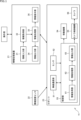
- FIG. 1 illustrates an example of a configuration of an information processing system.
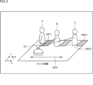
- FIG. 2 is a diagram illustrating a task space.
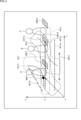
- FIG. 13 is a diagram illustrating mapping to a configuration space.
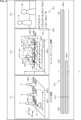
- FIG. 2 is a diagram showing an example of a display screen.
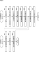
- 11 is a flowchart illustrating a map generation process and an advance preparation process.
- 4 is a flowchart illustrating a travel preparation process and a travel process. 4 is a flowchart illustrating a travel preparation process and a travel process.
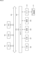
- FIG. 1 illustrates an example of the configuration of a computer.
- the present technology can be applied to an information processing system that plans a travel path for a robot having a photographing function when photographing one or more subjects.
- the information processing system of the present technology by mapping an area in which the subject can be photographed in a configuration space, it becomes possible to more easily plan a path.
- one example of filming using a robot would be filming a performance by multiple dancers.
- Specific examples would include switching the subject from dancer A to dancer B, or switching from a state showing dancer A to a state showing both dancers A and B.
- Condition a No obstacles between the subject and the robot
- Condition b Multiple people can be photographed at once
- Condition c Switch subjects as smoothly as possible
- mapping information about the subject and obstacles in the configuration space it is possible to easily determine a driving route that satisfies the above conditions a to c. In other words, it is possible to plan a route more easily.
- the position and orientation of the robot can be treated as a point.
- the robot's configuration space is three-dimensional.
- mapping the areas where a subject can be photographed it becomes easier to determine which subject can be photographed at which position, and locations to avoid and locations to pass through along the route become clear in three-dimensional space.
- FIG. 1 shows an example of the configuration of an embodiment of an information processing system to which this technology is applied.
- the information processing system 11 shown in FIG. 1 includes an information processing device 21, an environmental sensor 22, and a robot 23.
- an image of the configuration space of the robot 23, onto which information about subjects and obstacles is mapped, is displayed on the information processing device 21 operated by the operator, and the travel path of the robot 23 is appropriately planned.
- a robot 23 with a photographing function is placed in the space where the subject to be photographed is located (hereinafter referred to as the task space).
- the robot 23 travels through the task space along a travel route obtained by the plan while acquiring the output of an environmental sensor 22 that is placed at a position within the task space or at a position near the task space as appropriate, and photographs the subject.
- the information processing device 21 may be, for example, a personal computer or a tablet terminal, and executes a program to realize an application related to the travel path planning of the robot 23.
- the information processing device 21 has an information input unit 31, an information acquisition unit 32, an information processing unit 33, an information output unit 34, and an information presentation unit 35.
- the information input unit 31 is composed of input devices such as a mouse, keyboard, touch panel, etc., and supplies signals according to the operator's operations to the information acquisition unit 32.
- the information acquisition unit 32 has a communication unit that communicates with external devices, and receives signals from the information input unit 31 in response to operations by the operator, and information sent from the robot 23 to acquire specific information and supply it to the information processing unit 33.
- the information processing unit 33 controls the operation of the entire information processing device 21.
- the information processing unit 33 performs a predetermined information processing based on the information supplied from the information acquisition unit 32, and supplies the resulting image to the information presentation unit 35 for display, or supplies the information obtained by the information processing to the information output unit 34 for transmission to the robot 23.
- the information output unit 34 is, for example, a communication unit that communicates with an external device, and transmits various pieces of information supplied from the information processing unit 33 to the robot 23.
- the information presentation unit 35 is, for example, a display, and displays images supplied from the information processing unit 33.
- the environmental sensor 22 may be, for example, an RGB camera, an RGB-D camera, or a UWB (Ultra Wide Band) type sensor, and detects the position of the subject in the task space and transmits subject position information indicating the detection result to the robot 23.
- RGB camera an RGB-D camera
- UWB Ultra Wide Band
- Robot 23 is a mobile robot that travels through the task space and photographs the target subject.
- the robot 23 has a wireless communication unit 51, a sensor 52, a control unit 53, a movement mechanism 54, a camera control mechanism 55, and a camera 56.
- the wireless communication unit 51 performs wireless communication with external devices such as the information processing device 21 and the environmental sensor 22.
- the wireless communication unit 51 receives information transmitted from the information processing device 21 and the environmental sensor 22 and supplies it to the control unit 53, and transmits information supplied from the control unit 53 to the information processing device 21.
- the sensor 52 is composed of various sensors, such as a 2D or 3D LiDAR (Light Detection and Ranging) and an RGB-D camera.
- the sensor 52 detects the positions of subjects and obstacles in the task space and supplies the detection results to the control unit 53.
- the control unit 53 is composed of a computer that controls the overall operation of the robot 23.
- the control unit 53 has an information acquisition unit 61, an information processing unit 62, and an information output unit 63.
- the information acquisition unit 61 acquires various types of information by receiving information from the wireless communication unit 51 and acquiring the detection results of subjects and obstacles output from the sensor 52, and supplies the information to the information processing unit 62.
- the information processing unit 62 processes information based on the information supplied from the information acquisition unit 61, and supplies the various pieces of information obtained as a result to the information output unit 63 as appropriate.
- the control unit 53 operates the movement mechanism 54 and the camera control mechanism 55 according to the results of the information processing in the information processing unit 62.
- the information output unit 63 supplies the information provided by the information processing unit 62 to the wireless communication unit 51 and controls the transmission of the supplied information to the information processing device 21.
- the movement mechanism 54 operates according to the control of the control unit 53, and moves the robot 23 by rotating wheels or the like provided on the robot 23.
- the camera control mechanism 55 operates under the control of the control unit 53 to control the shooting direction of the camera 56 and the shooting of the subject by the camera 56.
- the camera 56 functions as a shooting unit that shoots the task space as the shooting target. That is, the camera 56 shoots the subject in the task space under the control of the camera control mechanism 55, and supplies the resulting images (moving images) to the control unit 53 or to a recording unit (not shown) for recording.
- the operator installs a running rail in the task space and the robot 23 runs along the running rail (hereinafter also referred to as the rail method), and the robot 23 runs autonomously (hereinafter also referred to as the autonomous running method).
- the information processing device 21 maps the area in which the subject can be photographed, the subject, obstacles, etc. into the configuration space and presents them to the operator.
- the image of the configuration space onto which the area in which the subject can be photographed, etc. are mapped will also be referred to as the configuration space image.
- the configuration space image visualizes the area in which the subject can be photographed, the subject's position, the positions of obstacles, etc. In other words, it visualizes which subject can be photographed at which position and posture of the robot 23.
- the information processing device 21 may determine candidates for the driving route of the robot 23 and display the candidates (hereinafter also referred to as candidate routes) on the configuration space image.
- the candidate routes may be mapped and visualized in the configuration space to suggest driving routes to the operator.
- the operator can visually grasp the position where the subject can be photographed without obstacles being captured in the image, and can easily determine (decide) the travel route that allows the subject to be switched smoothly as intended. Once the operator has determined the travel route for the robot 23 while checking the configuration space image, he or she installs travel rails in the task space to allow the robot 23 to travel along that travel route.
- the horizontal direction in the figure is the x direction
- the depth direction in the figure is the y direction
- the positions of the robot 23, etc. are expressed by coordinates (x, y) in the xy coordinate space.
- the running rail RA11 is assumed to be temporary.
- the horizontal orientation of the camera 56 of the robot 23 in the task space i.e., the shooting direction of the camera 56, is represented by the angle ⁇ .
- the configuration space of the robot 23 is a space whose axes are the degrees of freedom of the robot 23.
- the configuration space is a three-dimensional space consisting of an x coordinate (x axis) indicating the position of the robot 23, a y coordinate (y axis) indicating the position of the robot 23, and an angle ⁇ ( ⁇ axis) indicating the shooting direction by the robot 23.
- a position (point) in the configuration space represents one position and posture of the robot 23 in the task space.
- the posture here refers to the angle ⁇ that indicates the shooting direction of the camera 56 on the robot 23.
- the horizontal, depth, and vertical directions correspond to the x-axis, y-axis, and ⁇ -axis directions, respectively.
- a self-position mark MK11 indicating the position and posture of the robot 23, the imageable areas R11 to R13, and the candidate routes RT11 to RT15 are also mapped (superimposed) in the configuration space.
- the self-position mark MK11 is information indicating a position (point) in the configuration space that corresponds to the position (x, y) and posture (angle ⁇ ) of the robot 23 in the task space at a specific timing, such as the current time.
- the self-position mark MK11 is displayed at a position in the configuration space that is determined by the position (x, y) and angle ⁇ of the robot 23 at a specific timing.
- the self-position mark MK11 may be any type of mark, such as an icon representing the robot 23 or an image of the robot 23 itself.
- the operator can ascertain the position and posture (photography direction) of the robot 23 by checking the display position of the self-position mark MK11.
- the photographable area R11 is a three-dimensional area (space) that indicates the range of positions and orientations of the robot 23 in which the subject A can be photographed.
- the photographable area R11 is the area in the configuration space in which the robot 23 can photograph the subject A.
- the robot 23 can photograph the subject A.
- the photographable area R12 is an area indicating the range of positions and postures of the robot 23 capable of photographing subject B
- the photographable area R13 is an area indicating the range of positions and postures of the robot 23 capable of photographing subject C.
- robot 23 can capture an image that includes subjects A to C as subjects.
- Candidate routes RT11 to RT15 indicate candidate routes for the robot 23 to travel in the configuration space when the robot 23 photographs one or more subjects while traveling in the task space, as calculated by the information processing device 21. That is, candidate routes RT11 to RT15 indicate candidate routes for travel proposed to the operator by the information processing device 21, more specifically, candidate routes for the travel and the postures of the robot 23 at each position on the travel route. Each candidate route is calculated based on, for example, the calculation results of the photographable area, etc.
- the operator can easily understand which subjects will be captured on each candidate route by visually checking which captureable areas each candidate route passes through.
- the robot 23 takes pictures while moving along the candidate route RT11, the state changes over time from one in which subjects A and B are photographed to one in which only subject A is photographed.
- photographs can be taken without a situation in which none of subjects A to C are absent from the picture as a subject.
- smooth switching between subjects can be achieved.
- candidate route RT12 the state changes from one in which subjects A and B are photographed to one in which subjects A, B, and C are photographed, and then the state changes again to one in which subjects B and C are photographed.
- smooth subject switching can be achieved.
- candidate route RT13 the state changes from one in which subject C is being photographed to one in which subjects B and C are being photographed, and then the state changes again to one in which subject B is being photographed.
- smooth subject switching can be achieved.
- candidate route RT14 the state changes from one in which subject A is photographed to one in which none of subjects A to C are photographed, and then the state changes again to one in which subject A is photographed.
- candidate route RT15 the state changes from one in which subject B is photographed to one in which none of subjects A to C are photographed, then to one in which subject C is photographed, and then to one in which none of subjects A to C are photographed.
- candidate routes RT14 and RT15 there are periods when the target subject is not captured, i.e., periods when none of the target subjects A to C are included in the image, so it cannot be said that smooth switching of subjects can be achieved. Therefore, such candidate routes RT14 and RT15 need to be modified as necessary.
- the information presentation unit 35 displays an image of the configuration space in which the subject, obstacles, running rails, self-position mark, photographable area, and candidate routes are mapped (displayed) as shown in FIG. 3 as a configuration space image.
- the configuration space image displays images of models representing the subjects or obstacles, rather than the mapped subjects or obstacles themselves.
- the operator can edit (modify) the travel route indicated by the travel rail RA11 by performing operations on the displayed travel rail RA11 (configuration space image).
- editing (modification) of the travel rail RA11 is possible.
- editing (modification) of the candidate routes RT11 to RT15 is possible by performing operations on the configuration space image.
- the operator can instantly visually grasp the position and posture at which the subject can be photographed, the placement of the subject and obstacles, and the travel path along the travel rails. Therefore, the operator can more easily plan the path of the robot 23 by referring to the configuration space image.
- the positions of the subject and robot 23 are visualized on a two-dimensional plane.
- the positions of the subject and robot 23 arranged on a two-dimensional plane are referenced to perform route planning.
- the operator must determine each time the posture of the robot 23 that will enable it to photograph the desired subject, but it is difficult to determine the posture based only on the positional relationship on a two-dimensional plane. Furthermore, it becomes even more difficult when there are many subjects (people) and obstacles, or when determining a travel route rather than just one photographing location.
- the information processing system 11 can present an image of the configuration space shown in FIG. 3, for example, to more easily plan the travel path of the robot 23 compared to a case where the path is planned based only on positional relationships on a two-dimensional plane.
- the imageable area R11 to imageable area R13 for each subject is a three-dimensional area that takes into account not only the x- and y-direction positions of the robot 23 capable of photographing the subject, but also the posture (image-taking direction) of the robot 23 capable of photographing the subject, i.e., the angle ⁇ .
- the operator can instantly visually grasp the position and posture of the robot 23 that can photograph the desired subject.
- the autonomous traveling method in which the robot 23 autonomously plans the route can also make route planning easier by using a configuration space image.
- the robot 23 makes autonomous decisions (route planning) and photographs the subject while autonomously driving in accordance with those decisions.
- the travel path of the robot 23 is planned using information on the configuration space in which the photographable area, etc. is mapped, i.e., the above-mentioned configuration space image, as well as action plan information provided by the operator, etc.
- the action policy information is information that indicates the policy for photographing and movement (driving), such as which subject the robot wants to photograph and how it should drive (move), i.e., the action policy of the robot 23 regarding photographing and movement when photographing.
- the action policy information can specify a course of action regarding photography, such as taking pictures of as many people as possible at the same time, always taking pictures of subject A, making sure that subject C does not get in the shot (does not appear in the picture), taking pictures of subject A in the first half of the shoot and subject B in the second half of the shoot, etc.
- the action policy for movement can be specified by the action policy information, such as continuing to move around the stage (task space) or going back and forth to the front of the stage.
- the robot 23 autonomously determines a travel route along which it will move (run) and take photographs in accordance with the action policy indicated by the action policy information.
- the information presentation unit 35 of the information processing device 21 display a screen including a configuration space image.
- FIG. 4 shows an example of a display screen displayed on the information presentation unit 35. Note that in FIG. 4, parts corresponding to those in FIG. 2 or FIG. 3 are given the same reference numerals, and their explanation will be omitted as appropriate.
- a task space image P11 which is an image of the task space shown in FIG. 2
- a configuration space image P12 which is an image of the configuration space shown in FIG. 3, are displayed side by side.
- the task space image P11 is an image of a task space, which is a typical three-dimensional space, i.e., a space of an xyz coordinate system, in which the subject, obstacles, traveling rails, and robot 23 are arranged.
- the task space image P11 is an image that visually shows the respective positions of the subject, obstacles, traveling rails, and robot 23.
- the configuration space image P12 is an image of the configuration space, which is a space whose axes are the degrees of freedom of the robot 23.
- the configuration space image P12 displays the subjects, obstacles, running rails, and the self-position mark of the robot 23, as well as the photographable area of each subject and multiple candidate routes.
- the operator can edit (modify) the travel rails and candidate routes by, for example, operating the information input unit 31 to operate the task space image P11 and the configuration space image P12 on the display screen, particularly the travel rails and candidate routes.
- the operator can change the travel route of the robot 23 indicated by the travel rails and candidate routes by editing (modifying) the travel rails and candidate routes.
- the captured image P13 is displayed to the right of the configuration space image P12.
- the captured image P13 is an image that is obtained by capturing an image when the robot 23 is in the position and posture indicated by the self-position mark, and is generated, for example, by a simulation based on the position of the subject and the position and posture of the robot 23.
- the captured image P13 is a simulation image that corresponds to an image that would be captured by the robot 23.
- candidate routes proposed by the information processing device 21 and check boxes for selecting the candidate routes are displayed side by side. In other words, a list of candidate routes is displayed. Note that multiple candidate routes may be displayed, or only one may be displayed.
- candidate routes RT11 to RT13 are presented as possible driving routes. Also, a check mark is displayed in the check box CB11, which indicates that the candidate route RT11 corresponding to the check box CB11 is selected. Therefore, an image obtained when the robot 23 is caused to drive (move) along the candidate route RT11 is displayed as the captured image P13.
- the portion of the display screen indicated by the arrow Q12 displays a timeline indicating the period during which one or more subjects are photographed, determined by the information processing unit 33 based on the photographable area, etc.
- the display bar BR11 in the timeline indicates the section (time) during which subject A is photographed
- the display bar BR12 indicates the section (time) during which subject B is photographed.
- candidate route RT11 is selected by check box CB11, so display bars are displayed for subjects A and B that will be captured as subjects (will be the subjects) when the robot 23 takes a photograph along candidate route RT11.
- the operator can also move cursor CS11 on the timeline as appropriate.
- the task space image P11, configuration space image P12, and captured image image P13 change according to the position of cursor CS11, i.e., the time indicated by cursor CS11.
- the position of the subject and the position and posture of the robot 23 may change over time.
- the positions of obstacles may also change over time.
- the photographable area also changes over time.
- the positions of the subject and obstacles, the position and posture of the robot 23 (position of the self-position mark), and the captureable area change depending on the position of the cursor CS11.
- the captured image image P13 also changes depending on the changes in the task space image P11 and the configuration space image P12.
- the operator can easily grasp how the subject, obstacles, the position and posture of the robot 23, the area that can be photographed, and the photographed image P13 change over time. In particular, by looking at the photographed image P13, the operator can visually grasp what kind of image will actually be photographed.
- the robot 23 When the robot 23 is placed in the task space, it starts the map generation process. In this case, it is assumed that at least an obstacle is present in the task space, and the target subject may or may not be placed in the task space.
- step S11 the information acquisition unit 61 of the robot 23 collects information to generate map information that indicates the task space.
- the operator operates the information processing device 21 as appropriate to cause the robot 23 to travel in the task space.
- the information acquisition unit 61 uses the sensor 52, wireless communication unit 51, and camera 56 to collect information required to generate map information and supplies it to the information processing unit 62.
- the information acquisition unit 61 collects the detection results of the positions of obstacles and subjects obtained by the sensor 52, images captured by the camera 56, and the detection results of the positions of subjects received from the environmental sensor 22 by the wireless communication unit 51, as information necessary for generating map information.
- step S12 the information processing unit 62 generates map information of the task space based on the information collected in step S11 and supplied from the information acquisition unit 61.
- map information of the task space which indicates the shape of the task space and the size and shape of obstacles located at which positions in the task space. If a subject is placed in the task space, information such as the subject's position can also be obtained from the map information.
- the information processing unit 62 supplies the generated map information to the wireless communication unit 51 via the information output unit 63 and instructs it to be transmitted to the information processing device 21.
- step S13 the wireless communication unit 51 transmits the map information provided by the information output unit 63 to the information processing device 21.
- the robot 23 may travel in the task space as appropriate and transmit information indicating the position of the subject in the task space to the information processing device 21.
- the information indicating the position of the subject is obtained (acquired), for example, by the environmental sensor 22 or the sensor 52.
- step S13 When the processing of step S13 is performed and the map information is sent, the information processing device 21 starts the advance preparation processing.
- step S31 the information acquisition unit 32 receives the map information sent from the robot 23 and supplies it to the information processing unit 33.
- step S32 the information processing unit 33 reads the obstacle positions in the task space based on the map information provided by the information acquisition unit 32.
- the information processing unit 33 extracts (reads) information regarding the obstacle's position from the map information and uses it as obstacle position information.
- step S33 the information processing unit 33 sets the subject position in the task space.
- the information processing unit 33 extracts (reads) the information about the subject's position from the map information and sets it as subject position information.
- the information processing unit 33 generates subject position information indicating the position of each of the one or more subjects based on information regarding the position of each of the subjects in the task space acquired by the information acquisition unit 32.
- the information acquisition unit 32 acquires a signal output from the information input unit 31 in response to that operation as information relating to the subject's position. Also, for example, when information relating to the subject's position is transmitted from the robot 23, the information acquisition unit 32 receives that information to acquire information relating to the subject.
- the information processing unit 33 sets the subject position by placing the subject at the position in the task space indicated by the subject position information obtained in this manner.
- step S34 the information processing unit 33 reflects the obstacle position and subject position in the task space in the configuration space.
- the information processing unit 33 maps (places) the obstacles and subjects in the task space onto the configuration space based on the obstacle position information and subject position information obtained in steps S32 and S33.
- step S35 the information processing unit 33 calculates the photographable area of the subject in the configuration space based on the mapping results of the subject and obstacles into the configuration space, in other words, the position of each subject and the position of each obstacle in the task space.
- step S35 a three-dimensional area consisting of a position (x, y) in the task space where the robot 23 can photograph the subject and a position (point) in the configuration space corresponding to the posture (angle ⁇ ) of the robot 23 at that position is calculated for each subject.
- a position and orientation that allows for capturing an image of a subject is one that allows for an image to be obtained that includes the desired subject and does not include any obstacles when capturing an image with camera 56.
- the position and orientation at which the subject can be photographed may be any position and orientation that satisfies predetermined conditions regarding the subject and obstacles, such as the subject not being partially or completely obscured by an obstacle in the captured image.
- step S35 for example, the imageable area R11 to imageable area R13 shown in Figure 3 are calculated.
- step S36 the information processing unit 33 visualizes the imageable area of each subject obtained in step S35.
- the information processing unit 33 generates display data (image data) for a display screen on which an image of the configuration space onto which each subject, obstacle, and the photographable area of each subject are mapped is displayed, and supplies the display data to the information presentation unit 35 to display the display screen.
- This display data particularly the configuration space image and task space image, is generated based on, for example, the subject position and obstacle position in the task space, the calculation results of the photographable area, map information, etc.
- the travel rails are not displayed on the task space image, and the travel rails and candidate routes are not displayed on the configuration space image.
- the task space image displays the subject and obstacles, but does not display the travel rails or robot 23.
- the travel rails and robot 23 may be displayed in a temporary position, such as a predetermined position, on the task space image.
- the configuration space image displays the subject and obstacles, i.e., the position of the subject and the position of the obstacle, and the photographable area for each subject, but does not display the self-position mark, traveling rails, or candidate routes.
- the self-position mark and traveling rails may be displayed at a provisional position, such as a predetermined position, on the configuration space image.
- the robot 23 generates map information of the task space and transmits it to the information processing device 21.
- the information processing device 21 also receives map information from the robot 23, calculates the photographable area, visualizes the photographable area, and presents it to the operator.
- step S61 the information processing unit 33 sets the travel rails based on the signal supplied from the information input unit 31 via the information acquisition unit 32 in response to the operator's operation.
- the operator when the operator causes the information presentation unit 35 to display a display screen including a task space image and a configuration space image, the operator operates the information input unit 31 to operate the display screen and place a temporary running rail on the configuration space image.
- a screen similar to the display screen shown in FIG. 4 is displayed as the display screen, and a self-position mark is also displayed appropriately on the configuration space image on the display screen. Note that at this point, the running rail is not displayed on the task space image.
- the operator When the operator has displayed the temporary running rails on the configuration space image, he or she can check the temporary running rails and further operate the information input unit 31 to appropriately change the installation position (placement position) and length of the temporary running rails, i.e., the route of the running rails.
- the information processing unit 33 controls the information presentation unit 35 in response to a signal supplied from the information input unit 31 via the information acquisition unit 32, and sets the running rails by changing the position of the running rails on the configuration space image, etc.
- step S62 the information processing unit 33 reflects the settings made in step S61 in the task space.
- the information processing unit 33 maps (places) the traveling rails set in the configuration space in step S61 onto the task space.
- the running rails are displayed in the same position on the task space image on the display screen displayed by the information presentation unit 35 as they are on the configuration space image.
- step S63 the information processing unit 33 suggests a driving route.
- the information processing unit 33 calculates candidate routes based on the positions of subjects and obstacles, the photographable area for each subject, and the position and route of the traveling rails.
- action plan information input by the operator may be used as appropriate.
- the information processing unit 33 When the information processing unit 33 calculates the candidate route, it controls the information presentation unit 35 according to the calculation result and updates the display on the display screen. In other words, the information processing unit 33 suggests a travel route for the robot 23 to the operator by displaying a list of the candidate routes on the display screen or by displaying one or more candidate routes on the configuration space image.
- the operator can then check the position of the traveling rails while looking at the display screen, or can modify the position of the traveling rails by operating the information input unit 31.
- the operator can select a presented candidate route, modify the selected candidate route as appropriate, and use the modified candidate route as the final traveling route for the robot 23 indicated by the traveling rails.
- step S64 the information processing unit 33 corrects the traveling rails based on the signal supplied from the information input unit 31 via the information acquisition unit 32 in response to the input operation of the operator. In other words, the final traveling path of the robot 23 is determined in response to the input operation of the operator.
- step S65 the information processing unit 33 generates travel path information indicating the travel path of the robot 23 along the travel rail based on the finally determined position of the travel rail, and supplies this information to the information output unit 34.
- the travel route information includes not only information indicating the travel route of the robot 23, but also speed information and attitude information (angle ⁇ ) for each section of the travel route, such as the speed and attitude at which the robot 23 will travel along the travel route.
- step S66 the information output unit 34 transmits the travel route information provided by the information processing unit 33 to the robot 23.
- actual travel rails are installed appropriately in the task space.
- step S81 the wireless communication unit 51 of the robot 23 receives the travel route information transmitted from the information processing device 21, and supplies the travel route information to the information processing unit 62 via the information acquisition unit 61.
- step S82 the information processing unit 62 controls the travel of the robot 23 based on the travel path information provided by the information acquisition unit 61.
- the information processing unit 62 controls the movement mechanism 54 while determining the position and posture of the robot 23 based on the travel route information, the map information generated in step S12 of FIG. 5, and information supplied from the information acquisition unit 61 as appropriate, to cause the robot 23 to travel.
- the robot 23 travels along the travel route indicated by the travel route information at the speed and direction (angle ⁇ ) indicated by the travel route information.
- the information processing unit 62 controls the camera control mechanism 55 as appropriate based on the travel route information, causing the camera 56 to take a picture.
- the information received from the information acquisition unit 61 during driving control of the robot 23 may be, for example, the detection results of the subject position by the environmental sensor 22, the detection results of the positions of the subject and obstacles by the sensor 52, and images (video) captured by the camera 56.
- the information processing unit 62 estimates (determines) the position and posture of the robot 23 based on the detection results of the positions of the subject and obstacles, the images of the task space captured by the camera 56, map information, driving route information, etc.
- the information processing unit 62 generates self-location information indicating the position and posture of the robot 23 at each time while the robot 23 is moving, and supplies this to the wireless communication unit 51 via the information output unit 63.
- step S83 the wireless communication unit 51 transmits the self-location information provided by the information output unit 63 to the information processing device 21, and the running process ends.
- the self-location information is transmitted successively until the robot 23 finishes running.
- the information processing device 21 performs the process of step S67.
- step S67 the information acquisition unit 32 receives the self-location information transmitted from the robot 23 by the processing of step S83 and supplies it to the information processing unit 33.
- step S68 the information processing unit 33 reflects the self-location information provided by the information acquisition unit 32 in the task space image and configuration space image displayed on the information presentation unit 35.
- the information processing unit 33 causes the information presentation unit 35 to display a screen similar to the display screen shown in FIG. 4.
- the information processing unit 33 when self-location information at each time is received from the robot 23, the information processing unit 33 generates a task space image in which the position and posture of the robot 23 are the position and posture indicated by the received self-location information, and displays it on the display screen.
- the information processing unit 33 generates a configuration space image and displays it on the display screen so that the self-position mark in the configuration space is displayed at a position corresponding to the position and attitude indicated by the received self-position information.
- the received self-position information of the robot 23 is reflected in the task space image and the configuration space image.
- the information processing unit 33 also generates a simulated captured image based on a configuration space image reflecting the self-position information, i.e., information on the configuration space on which subjects and obstacles are mapped, and travel route information, and displays the image on the display screen. This allows the operator to easily understand the images captured by the robot 23. Note that while the robot 23 is traveling, an image actually captured by the robot 23 may be displayed instead of the captured image.
- the information processing unit 33 continues to perform the process of step S68 until the robot 23 has finished moving, at which point the moving preparation process ends.
- the information processing device 21 displays a display screen including a task space image and a configuration space image, sets the travel rails and generates travel route information in response to the operator's operation, and reflects the self-position information of the robot 23 while traveling on the display screen.
- the robot 23 receives travel route information from the information processing device 21, it travels based on the travel route information and transmits its self-position information to the information processing device 21.
- the information processing system 11 performs the map generation process and advance preparation process described with reference to FIG. 5.
- the information processing system 11 then performs the driving preparation process and driving process shown in FIG. 7.
- step S111 the information processing unit 33 sets a course of action based on a signal supplied from the information input unit 31 via the information acquisition unit 32 in response to the operator's operation.
- the information presentation unit 35 displays a display screen including a task space image and a configuration space image.
- the task space image and the configuration space image do not display the running rails.
- the configuration space image does not display any candidate routes.
- the operator operates the information input unit 31 while viewing the display screen as appropriate to input the action plan of the robot 23 during shooting, such as which subject the operator wants to shoot and how the robot should drive.
- the information processing unit 33 then generates action plan information indicating the action plan input by the operator in response to a signal supplied from the information input unit 31 via the information acquisition unit 32.
- the information processing unit 33 generates configuration space information indicating the positions of subjects and obstacles in the configuration space and the imageable area based on the configuration space image, etc.
- the configuration space information is information about the configuration space, and includes at least information indicating the imageable area.
- the information processing unit 33 supplies the action policy information and configuration space information to the information output unit 34 and instructs it to be transmitted to the robot 23.
- step S112 the information output unit 34 transmits the action policy information and configuration space information provided by the information processing unit 33 to the robot 23.
- the robot 23 starts running and performs the process of step S131.
- step S131 the wireless communication unit 51 receives the action policy information and configuration space information transmitted from the information processing device 21, and supplies the action policy information and configuration space information to the information processing unit 62 via the information acquisition unit 61.
- step S132 the information processing unit 62 controls the movement of the robot 23 based on the action plan information and configuration space information supplied from the information acquisition unit 61.
- the information processing unit 62 controls the moving mechanism 54 based on the action plan information and configuration space information, the map information generated in step S12 of FIG. 5, and information supplied from the information acquisition unit 61 as appropriate, to cause the robot 23 to move autonomously.
- the information that the information processing unit 62 receives from the information acquisition unit 61 may be, for example, the detection result of the subject position by the environmental sensor 22, the detection result of the subject and obstacle positions by the sensor 52, and the image (video) captured by the camera 56.
- the information processing unit 62 identifies (estimates) the position and posture of the robot 23 based on the action policy information, configuration space information, map information, etc., and autonomously determines a travel route that follows the action policy indicated by the action policy information.
- the information processing unit 62 controls the movement mechanism 54 to make the robot 23 move along the determined travel route, and also controls the camera control mechanism 55 as appropriate to take pictures with the camera 56. This allows the robot 23 to move and take pictures while autonomously determining its own travel route.
- the information processing unit 62 generates self-location information indicating the position and posture of the robot 23 at each time while it is moving, similar to the case in step S82 of FIG. 6, and supplies the self-location information to the wireless communication unit 51 via the information output unit 63.
- step S133 the wireless communication unit 51 transmits the self-location information provided by the information output unit 63 to the information processing device 21, and the running process ends.
- the self-location information is transmitted successively until the robot 23 finishes running.
- step S133 the information processing device 21 then performs the processes of steps S113 and S114, and the travel preparation process ends. Note that the processes of steps S113 and S114 are similar to the processes of steps S67 and S68 in FIG. 6, so a description thereof will be omitted.
- the information processing device 21 transmits the action policy information and the configuration space information to the robot 23. Furthermore, the robot 23 autonomously determines a travel route based on the action policy information and the configuration space information, and travels along the route.
- the robot 23 can more easily autonomously determine an appropriate travel route. In other words, it is easier to plan a travel route.
- Example of computer configuration The above-mentioned series of processes can be executed by hardware or software.
- the program constituting the software is installed in a computer.
- the computer includes a computer built into dedicated hardware, and a general-purpose personal computer, for example, capable of executing various functions by installing various programs.
- FIG. 8 is a block diagram showing an example of the hardware configuration of a computer that executes the above-mentioned series of processes using a program.
- a CPU Central Processing Unit
- ROM Read Only Memory
- RAM Random Access Memory
- an input/output interface 505 Connected to the input/output interface 505 are an input unit 506, an output unit 507, a recording unit 508, a communication unit 509, and a drive 510.
- the input unit 506 includes a keyboard, mouse, microphone, imaging element, etc.
- the output unit 507 includes a display, speaker, etc.
- the recording unit 508 includes a hard disk, non-volatile memory, etc.
- the communication unit 509 includes a network interface, etc.
- the drive 510 drives a removable recording medium 511 such as a magnetic disk, optical disk, magneto-optical disk, or semiconductor memory.
- the CPU 501 loads a program recorded in the recording unit 508, for example, into the RAM 503 via the input/output interface 505 and the bus 504, and executes the program, thereby performing the above-mentioned series of processes.
- the program executed by the computer (CPU 501) can be provided by being recorded on a removable recording medium 511 such as a package medium, for example.
- the program can also be provided via a wired or wireless transmission medium such as a local area network, the Internet, or digital satellite broadcasting.
- a program can be installed in the recording unit 508 via the input/output interface 505 by inserting the removable recording medium 511 into the drive 510.
- the program can also be received by the communication unit 509 via a wired or wireless transmission medium and installed in the recording unit 508.
- the program can be pre-installed in the ROM 502 or the recording unit 508.
- the program executed by the computer may be a program in which processing is performed chronologically in the order described in this specification, or a program in which processing is performed in parallel or at the required timing, such as when called.
- this technology can be configured as cloud computing, in which a single function is shared and processed collaboratively by multiple devices over a network.
- each step described in the above flowchart can be executed by a single device, or can be shared and executed by multiple devices.
- a single step includes multiple processes
- the processes included in that single step can be executed by a single device, or can be shared and executed by multiple devices.
- this technology can also be configured as follows:
- the information processing system Calculating an image capturing area in a configuration space of a robot that captures the object based on the position of one or more objects in the task space, in which the robot can capture the object; An information processing method comprising the step of displaying an image of the configuration space in which the photographable area is displayed.
- An information processing method comprising the step of displaying an image of the configuration space in which the photographable area is displayed.
- the information processing method according to any one of the preceding claims further comprising: calculating the imageable area for each of the subjects.
- the information processing method according to any one of (1) to (3) further comprising displaying an image of the configuration space in which a position of an obstacle in the task space and the imageable area are displayed.
- the information processing method according to any one of (1) to (11), further comprising: generating an image captured by the robot through a simulation based on a position and posture of the robot; and further displaying the image generated through the simulation.
- the information processing method according to any one of (1) to (12), further comprising displaying a timeline indicating a period during which one or more of the subjects are photographed based on the photographable area.
- the information processing method according to any one of (1) to (13), further comprising: determining a travel route of the robot in response to an operation by an operator; and transmitting travel route information indicating the determined travel route to the robot.
- An information processing device comprising: an information processing unit that calculates a captureable area in a configuration space of a robot that captures one or more subjects based on the positions of the subjects in a task space, the robot being able to capture the subjects, and displays an image of the configuration space in which the captureable area is displayed.
- Information processing system 21 Information processing device, 22 Environmental sensor, 23 Robot, 31 Information input unit, 32 Information acquisition unit, 33 Information processing unit, 34 Information output unit, 35 Information presentation unit, 51 Wireless communication unit, 52 Sensor, 53 Control unit, 54 Movement mechanism, 55 Camera control mechanism, 56 Camera, 61 Information acquisition unit, 62 Information processing unit, 63 Information output unit
Landscapes
- Engineering & Computer Science (AREA)
- Multimedia (AREA)
- Signal Processing (AREA)
- Aviation & Aerospace Engineering (AREA)
- Radar, Positioning & Navigation (AREA)
- Remote Sensing (AREA)
- Physics & Mathematics (AREA)
- General Physics & Mathematics (AREA)
- Automation & Control Theory (AREA)
- Human Computer Interaction (AREA)
- Control Of Position, Course, Altitude, Or Attitude Of Moving Bodies (AREA)
Abstract
La présente technologie concerne un procédé de traitement d'informations, un dispositif de traitement d'informations, et un programme au moyen desquels un itinéraire peut être planifié plus facilement. Le dispositif de traitement d'informations comprend une unité de traitement d'informations qui calcule, sur la base de la position d'un ou de chaque sujet d'une pluralité de sujets dans un espace de tâche, une région photographique dans laquelle un robot peut photographier le sujet dans un espace de configuration du robot qui photographie le sujet, et affiche une image de l'espace de configuration dans lequel la région photographique est affichée. La présente technologie peut être appliquée à des systèmes de traitement d'informations.
Applications Claiming Priority (2)
| Application Number | Priority Date | Filing Date | Title |
|---|---|---|---|
| JP2023076541 | 2023-05-08 | ||
| JP2023-076541 | 2023-05-08 |
Publications (1)
| Publication Number | Publication Date |
|---|---|
| WO2024232247A1 true WO2024232247A1 (fr) | 2024-11-14 |
Family
ID=93430002
Family Applications (1)
| Application Number | Title | Priority Date | Filing Date |
|---|---|---|---|
| PCT/JP2024/015670 Ceased WO2024232247A1 (fr) | 2023-05-08 | 2024-04-22 | Procédé de traitement d'informations, dispositif de traitement d'informations, et programme |
Country Status (1)
| Country | Link |
|---|---|
| WO (1) | WO2024232247A1 (fr) |
Citations (4)
| Publication number | Priority date | Publication date | Assignee | Title |
|---|---|---|---|---|
| JP2007214803A (ja) * | 2006-02-08 | 2007-08-23 | Canon Inc | 撮影制御装置及び撮影制御方法 |
| JP2016082441A (ja) * | 2014-10-17 | 2016-05-16 | ソニー株式会社 | 制御装置、制御方法及びコンピュータプログラム |
| US20200036886A1 (en) * | 2019-08-16 | 2020-01-30 | Lg Electronics Inc. | Method for photographing an unmanned aerial robot and a device for supporting the same in an unmanned aerial vehicle system |
| WO2022054655A1 (fr) * | 2020-09-14 | 2022-03-17 | ソニーグループ株式会社 | Dispositif mobile, système de capture d'images et procédé de commande d'un dispositif mobile |
-
2024
- 2024-04-22 WO PCT/JP2024/015670 patent/WO2024232247A1/fr not_active Ceased
Patent Citations (4)
| Publication number | Priority date | Publication date | Assignee | Title |
|---|---|---|---|---|
| JP2007214803A (ja) * | 2006-02-08 | 2007-08-23 | Canon Inc | 撮影制御装置及び撮影制御方法 |
| JP2016082441A (ja) * | 2014-10-17 | 2016-05-16 | ソニー株式会社 | 制御装置、制御方法及びコンピュータプログラム |
| US20200036886A1 (en) * | 2019-08-16 | 2020-01-30 | Lg Electronics Inc. | Method for photographing an unmanned aerial robot and a device for supporting the same in an unmanned aerial vehicle system |
| WO2022054655A1 (fr) * | 2020-09-14 | 2022-03-17 | ソニーグループ株式会社 | Dispositif mobile, système de capture d'images et procédé de commande d'un dispositif mobile |
Similar Documents
| Publication | Publication Date | Title |
|---|---|---|
| JP7236565B2 (ja) | 位置姿勢決定方法、装置、電子機器、記憶媒体及びコンピュータプログラム | |
| US10818099B2 (en) | Image processing method, display device, and inspection system | |
| JP7073850B2 (ja) | 入力装置および入力装置の入力方法 | |
| US20180190014A1 (en) | Collaborative multi sensor system for site exploitation | |
| JP6598191B2 (ja) | 画像表示システムおよび画像表示方法 | |
| CN105666505A (zh) | 具备扩展现实对应显示器的机器人系统 | |
| CN110915201B (zh) | 图像显示系统以及方法 | |
| JP7745167B2 (ja) | 撮影方法及び撮影装置 | |
| US20230326098A1 (en) | Generating a digital twin representation of an environment or object | |
| JP2024114712A (ja) | 撮像装置、撮像方法、及び、プログラム | |
| JP6725736B1 (ja) | 画像特定システムおよび画像特定方法 | |
| JP4227037B2 (ja) | 撮像システム及び校正方法 | |
| JP7334460B2 (ja) | 作業支援装置及び作業支援方法 | |
| CN115836262B (zh) | 基于图像的轨迹规划方法和运动控制方法以及使用该些方法的移动机器 | |
| JPWO2014102995A1 (ja) | モニタリングシステム、方法およびプログラムを記憶した情報記録媒体 | |
| WO2024232247A1 (fr) | Procédé de traitement d'informations, dispositif de traitement d'informations, et programme | |
| Scheuermann et al. | Mobile augmented reality based annotation system: A cyber-physical human system | |
| JP2021190729A (ja) | 画像特定システムおよび画像特定方法 | |
| JPH0386484A (ja) | ロボットの遠隔操作装置 | |
| ELzaiady et al. | Next-best-view planning for environment exploration and 3D model construction | |
| Safia et al. | Visual path following by an omnidirectional mobile robot using 2d visual servoing | |
| Fradet et al. | AR-Bot, a Centralized AR-based System for Relocalization and Home Robot Navigation. | |
| JP7685981B2 (ja) | 画像表示装置及び画像表示方法 | |
| JP4027294B2 (ja) | 移動体検出装置、移動体検出方法及び移動体検出プログラム | |
| JPH10124681A (ja) | 携帯型情報処理装置及び情報処理方法 |
Legal Events
| Date | Code | Title | Description |
|---|---|---|---|
| 121 | Ep: the epo has been informed by wipo that ep was designated in this application |
Ref document number: 24803360 Country of ref document: EP Kind code of ref document: A1 |
|
| NENP | Non-entry into the national phase |
Ref country code: DE |