WO2024241402A1 - Capteur de température et dispositif équipé d'un capteur de température - Google Patents
Capteur de température et dispositif équipé d'un capteur de température Download PDFInfo
- Publication number
- WO2024241402A1 WO2024241402A1 PCT/JP2023/018837 JP2023018837W WO2024241402A1 WO 2024241402 A1 WO2024241402 A1 WO 2024241402A1 JP 2023018837 W JP2023018837 W JP 2023018837W WO 2024241402 A1 WO2024241402 A1 WO 2024241402A1
- Authority
- WO
- WIPO (PCT)
- Prior art keywords
- temperature sensor
- temperature
- resin
- sensor according
- leads
- Prior art date
- Legal status (The legal status is an assumption and is not a legal conclusion. Google has not performed a legal analysis and makes no representation as to the accuracy of the status listed.)
- Ceased
Links
Images





Classifications
-
- G—PHYSICS
- G01—MEASURING; TESTING
- G01K—MEASURING TEMPERATURE; MEASURING QUANTITY OF HEAT; THERMALLY-SENSITIVE ELEMENTS NOT OTHERWISE PROVIDED FOR
- G01K7/00—Measuring temperature based on the use of electric or magnetic elements directly sensitive to heat ; Power supply therefor, e.g. using thermoelectric elements
- G01K7/16—Measuring temperature based on the use of electric or magnetic elements directly sensitive to heat ; Power supply therefor, e.g. using thermoelectric elements using resistive elements
- G01K7/22—Measuring temperature based on the use of electric or magnetic elements directly sensitive to heat ; Power supply therefor, e.g. using thermoelectric elements using resistive elements the element being a non-linear resistance, e.g. thermistor
-
- G—PHYSICS
- G01—MEASURING; TESTING
- G01K—MEASURING TEMPERATURE; MEASURING QUANTITY OF HEAT; THERMALLY-SENSITIVE ELEMENTS NOT OTHERWISE PROVIDED FOR
- G01K1/00—Details of thermometers not specially adapted for particular types of thermometer
- G01K1/08—Protective devices, e.g. casings
-
- G—PHYSICS
- G01—MEASURING; TESTING
- G01K—MEASURING TEMPERATURE; MEASURING QUANTITY OF HEAT; THERMALLY-SENSITIVE ELEMENTS NOT OTHERWISE PROVIDED FOR
- G01K7/00—Measuring temperature based on the use of electric or magnetic elements directly sensitive to heat ; Power supply therefor, e.g. using thermoelectric elements
- G01K7/16—Measuring temperature based on the use of electric or magnetic elements directly sensitive to heat ; Power supply therefor, e.g. using thermoelectric elements using resistive elements
- G01K7/18—Measuring temperature based on the use of electric or magnetic elements directly sensitive to heat ; Power supply therefor, e.g. using thermoelectric elements using resistive elements the element being a linear resistance, e.g. platinum resistance thermometer
Definitions
- the present invention relates to a durable temperature sensor that can be used in a range of temperatures from extremely low to high temperatures, and to a device equipped with a temperature sensor.
- thermistor temperature sensors which use a temperature-sensitive sintered body as a temperature-sensitive element, are used to detect the temperature of home appliances such as air conditioners, refrigerators, and water heaters, medical equipment, and in-vehicle equipment such as automobiles.
- Such temperature sensors are used in harsh temperature environments where the temperature of the environment is constantly changing, so they are required to be durable enough to withstand extremely low and high temperatures.
- temperature sensors have been proposed that improve heat cycle resistance, water resistance, and thermal response. Specifically, in a bottomed, pipe-shaped protective case, lead wires connected via electrodes placed on the surface of a temperature-sensitive sintered body are placed, and a filler (filled resin) is filled around the temperature-sensitive sintered body inside the protective case. This configuration prevents the filling resin from peeling off from the protective case due to heat cycles and escaping from the protective case together with the temperature-sensitive sintered body. Furthermore, these temperature sensors also have the problem of moisture due to low-temperature condensation penetrating around the temperature-sensitive sintered body, causing malfunctions.
- Air conditioners and freezers in particular have a wide range of temperatures, from extremely low temperatures below -80°C to abnormally high temperatures where the temperature of the outdoor unit's protruding pipe reaches as high as 150°C.
- the object of the present invention is to provide a temperature sensor and a device equipped with this temperature sensor that can not only prevent the malfunction of the temperature sensor escaping from the protective case together with the filled resin, but also suppress changes in the characteristics of the temperature sensor to ensure reliability.
- the embodiment of the present invention aims to provide a temperature sensor that can prevent short circuits even when used in a humid atmosphere by eliminating or minimizing gaps around the conductor (lead).
- a temperature sensor comprises a sensor element having a temperature sensing element and a pair of leads electrically connected to the temperature sensing element, a protective case that houses the sensor element, a filling material that fills the space between the protective case and the sensor element inside the protective case, an electric wire that is electrically connected to the leads and led out of the protective case, a sealing material made of an electrical insulator that covers from the heat sensing element to a predetermined position of the pair of leads, and a dipping resin made of an electrical insulator that covers from the sealing material to a predetermined position of the pair of leads and the electric wires, and is characterized in that the linear expansion coefficients of the sealing material, the dipping resin, the heat sensing element and the leads are set so that at least the dipping resin and the leads do not peel off during a temperature cycle of liquid nitrogen and boiling water.
- a device equipped with a temperature sensor according to an embodiment of the present invention is characterized in that it is equipped with a temperature sensor according to an embodiment of the
- Devices equipped with temperature sensors include various devices equipped with temperature sensors for detecting various temperatures, such as thermistors that use a temperature sensor as a temperature sensing element to detect the temperature of home appliances such as air conditioners, refrigerators, and water heaters, medical equipment, and in-vehicle equipment such as automobiles. There are no particular limitations on the devices to which temperature sensors can be applied.
- a temperature sensor and a device equipped with this temperature sensor which can prevent the problem of the temperature sensor escaping from the protective case together with the filled resin, and which can prevent the ingress of moisture even in harsh environments such as extremely low temperature and high temperature regions, thereby suppressing changes in the characteristics of the temperature sensor and ensuring reliability.
- thermosensor and a device equipped with a temperature sensor that can be used over a wide range of temperatures, from extremely low to high temperatures, and has good durability and a wide range of applications.
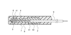
- FIG. 1 is a cross-sectional plan view showing a temperature sensor according to an embodiment of the present invention.
- FIG. 2 is a front cross-sectional view showing the temperature sensor.
- 4 is a table showing the linear expansion coefficient of each member of the temperature sensor.
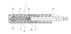
- FIG. 11 is a front cross-sectional view showing a temperature sensor according to another embodiment of the present invention.
- FIG. 11 is a cross-sectional plan view showing a temperature sensor according to another embodiment of the present invention.
- FIG. 4 is a front cross-sectional view showing a temperature sensor of a comparative example.
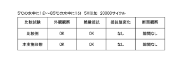
- 13 is a table showing comparative evaluation results in which 20,000 temperature cycles were performed, with one cycle consisting of immersion in water at 5° C. for 1 minute and immersion in water at 85° C.
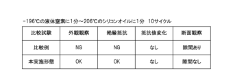
- 13 is a table showing comparative evaluation results in which 10 temperature cycles were performed, with the test conditions being 1 minute in liquid nitrogen at ⁇ 196° C. and 1 minute in silicone oil at 206° C.
- 13 is a table showing comparative evaluation results in which 20 temperature cycles were performed, with the test conditions being one minute in liquid nitrogen at ⁇ 196° C. and one minute in boiling water at 100° C.
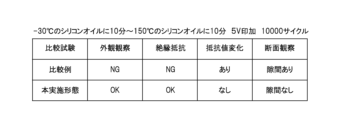
- 13 is a table showing comparative evaluation results in which 10,000 temperature cycles were performed, with the test conditions being ⁇ 30° C. silicon oil for 10 minutes and 150° C. silicon oil for 10 minutes per cycle.
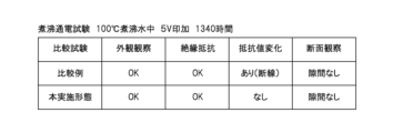
- the test conditions were a boiling current test, and the table shows the comparative evaluation results after 1,340 hours in boiling water at 100°C.
- Figs. 1 and 2 are plan and front cross-sectional views of the temperature sensor
- Fig. 3 is a table showing the linear expansion coefficients of each component
- Figs. 4 and 5 are front and plan cross-sectional views of a temperature sensor according to another embodiment of the present invention. Note that in each figure, the same or corresponding parts are given the same reference numerals and duplicate explanations are omitted. Also, the scale of each component has been appropriately changed for the purpose of explanation in order to make each component large enough to be recognized.
- the temperature sensor 1 is a temperature-sensitive resistor with temperature-sensing capabilities, and includes a protective case 2, a temperature sensor 3, leads 4, a sealing material 6, a dipping resin 7, a filling resin 8 as a filling body, and an electric wire 9.
- the temperature sensor 3 is preferably a temperature sensitive sintered body, but is not limited to a temperature sensitive sintered body and may be composed of a platinum resistor, a thin film thermistor, or a thermocouple, and is not limited to any particular type. In the case of a platinum resistor and a thin film thermistor formed on an insulating substrate, it is possible to make the thermal time constant extremely fast by making the substrate an extremely thin glass substrate.
- the sensor element is made up of the temperature sensor 3 and leads 4 of the temperature sensor.
- the temperature sensor 3 and leads 4 are connected and sealed with a sealing material 6.
- the leads 4 are electrically connected to each core 91 of the electric wire 9. Furthermore, the temperature sensor 3 is placed inside the protective case 2 and insulated with dipping resin 7, and is surrounded by a filling resin 8.
- the protective case 2 is made of resin or metal material, and is a pipe shape with one end open and a bottom, and is formed into a cylindrical or square tube shape.
- a cylindrical case with an outer diameter of 6 to 8 mm and a length of 20 to 30 mm is generally selected.
- the protective case 2 is made of resin, it is preferable to use a highly heat-resistant resin such as PPS (polyphenylene sulfide), liquid crystal polymer, PAI (polyamide-imide), or PEI (polyether-imide). This ensures heat resistance up to 200°C.
- PPS polyphenylene sulfide
- PAI polyamide-imide
- PEI polyether-imide
- the protective case 2 is made of metal, it is possible to use copper (Cu), iron (Fe), chromium (Cr), nickel (Ni), aluminum (Al), zinc (Zn), titanium (Ti), or an alloy containing at least one of these metals.
- the material of the protective case 2 is resin
- the resin protective case 2 by applying metal plating to the resin protective case 2, the water resistance and oil resistance of the temperature sensor 1 can be improved.
- the temperature sensor 3 is a temperature-sensitive sintered body, it is a thermistor formed in a roughly rectangular parallelepiped shape, and is composed of two or more elements selected from transition metal elements such as manganese (Mn), nickel (Ni), cobalt (Co), iron (Fe), yttrium (Y), chromium (Cr), copper (Cu), and zinc (Zn), and is composed of an oxide thermistor material containing a composite metal oxide having a crystalline structure as the main component. In addition, it may contain auxiliary components for improving characteristics, etc. The composition and content of the main component and auxiliary components can be appropriately determined according to the desired characteristics.
- the temperature sensor 3 may be made of silicon (Si) ceramics such as silicon carbide (SiC) and silicon nitride ( Si3N4 ).
- Si silicon
- SiC silicon carbide
- Si3N4 silicon nitride
- the shape of the thermistor is not limited to a substantially rectangular parallelepiped shape, and may be a disk shape, a polygonal shape, or any other suitable shape.
- the temperature sensor 3 can therefore be made of a compound semiconductor of metal oxide or metal nitride. Note that the temperature sensor 3 may have a Low B constant characteristic so that it can be used over a wide temperature range.
- An electrode layer 31 is formed on the surface of the temperature sensor 3.
- the leads 4 are a pair of conductive lead wires that are electrically connected by welding or soldering to an electrode layer 31 made of gold (Au), chromium (Cr), copper (Cu), platinum (Pt), etc., formed on the surface of the temperature sensor 3, and are led out from an opening on one end of the protective case 2.
- the leads 4 are electrically connected to each core 91 of the electric wire 9 by soldering, etc., and are insulated by an insulating coating 92.
- the electrode layer 31 and other components that make up the sensor element do not contain silver (Ag). This is to avoid migration.
- the preferred materials for the lead 4 are dumet wire and CP wire.
- the materials for the lead 4 are copper (Cu), iron (Fe), chromium (Cr), nickel (Ni), aluminum (Al), zinc (Zn), titanium (Ti), tin (Sn), or alloys containing at least one of these, and copper-plated wire, copper-tin-plated wire, or copper-clad wire with these as the core material.
- the lead 4 can be in any form, such as a solid wire or a square wire.
- the length of the lead 4 is usually 5 to 15 mm. It is selected taking into consideration the size of the protective case 2.
- the pair of leads 4 are formed with a bent portion 41 at the tip so that they are in parallel with the pitch of the core wire 91 of the electric wire 9. Specifically, a gap of 1 mm or more is maintained.
- the connection portion to the electrode layer 31, which is the tip of the lead 4, is arranged and connected in an oblique direction to the surface of the temperature sensor 3.
- the cross-sectional area of the lead 4 is 0.097 mm2 or less. It is considered that the cross-sectional area of the lead 4 is closely related to the change in the resistance value of the temperature sensor 3. There is a tendency that the change in the resistance value becomes larger as the cross-sectional area of the lead 4 becomes larger.
- the cross-sectional area of the lead 4 is small, 0.097 mm2 or less, it is possible to keep the change in resistance value small. This is presumably because if the lead 4 is thick and has a large cross-sectional area, a large force is applied to the temperature sensor 3. In addition, if the lead 4 is thin and has a small cross-sectional area, less heat is dissipated from the lead 4, enabling accurate temperature detection. Note that when multiple leads 4 are used, the cross-sectional area of the lead 4 can be determined by the total cross-sectional area of the multiple leads.
- the sealing material 6 covers and protects the temperature sensor 3, and is made of insulating resin such as epoxy resin with a high heat resistance. This allows the temperature sensor 3 and other components to be effectively protected even when used in a high-temperature environment.
- the sealing material 6 may also be an acid anhydride-based epoxy resin that contains a filler.
- Dipping resin 7 is provided around the temperature sensor 3, and a structure is formed in which insulation is ensured including between the leads 4 and each core wire 91 of the electrically connected electric wire 9.
- This dipping resin 7 is provided by dipping the temperature sensor 3 to which the leads 4 are connected, into insulating resin.
- a detailed description will be given focusing on the linear expansion coefficient of the dipping resin 7. This is a method for realizing the linear expansion coefficient of the dipping resin 7 to be 20 ⁇ 10 ⁇ 6 /° C. or less.
- the filling resin 8 is an epoxy resin, it is relatively easy to obtain epoxy resins with a linear expansion coefficient of 20 ⁇ 10 ⁇ 6 /° C. or less. Unlike the dipping resin 7, the filling resin 8 does not require thixotropy, and therefore it is relatively easy to achieve a linear expansion coefficient of 20 ⁇ 10 ⁇ 6 /° C. or less by adding an appropriate amount of filler to the base resin.
- epoxy resins are usually used by mixing two liquids, a base resin and a hardener.
- dip resin 7 thixotropy, which is the property that prevents the dipped resin from dripping, is required.
- thixotropy which is the property that prevents the dipped resin from dripping.
- the inventors have used a special compounding method to realize a dip epoxy resin that requires thixotropy and has a linear expansion coefficient of 20 ⁇ 10 -6 /° C. or less. Specifically, this is realized by adding at least one type of resin composition to a non-thixotropic epoxy resin that is a mixture of two liquids, a base resin and a hardener, to impart thixotropy. Unless such a special compounding method is used, it is difficult to obtain a dipped epoxy resin having a thixotropic linear expansion coefficient of 20 ⁇ 10 ⁇ 6 /° C. or less.
- the dip resin 7 may be an acid anhydride epoxy resin containing a filler.
- a dip epoxy resin having thixotropy and a linear expansion coefficient of 20 ⁇ 10 ⁇ 6 /° C. or less can be obtained.
- the thermal conductivity of the dip epoxy resin is improved, and the thermal time constant is increased.
- the thermal time constant is 10 seconds, whereas the thermal time constant of a dip epoxy resin containing a filler with good thermal conductivity is 5 seconds.
- the dip resin 7 containing a filler has a thermal conductivity of 0.6 W/m ⁇ K or more.
- the filling resin 8 is an acid anhydride-based epoxy resin, and fills the area around the temperature sensor 3, including the sealing material 5 that covers the temperature sensor 3 and the connection side of the lead 4 to the temperature sensor 3.
- the filling resin 8 may contain fillers such as ceramic, metal, and carbon that have good thermal conductivity.
- the linear expansion coefficient of the components is adjusted and set to 20 ⁇ 10 -6 /°C or less.
- the linear expansion coefficient of the temperature sensor 3, which is the temperature sensing element, the leads 4, the sealing material 6, the dipping resin 7, and the protective case 2 is preferably set to 7.5 to 19.5 ⁇ 10 -6 /°C, and specifically adjusted and set to 20 ⁇ 10 -6 /°C or less.
- Figure 4 shows a temperature sensor according to another embodiment of the present invention.
- Figure 4 shows a front cross-sectional view, and the temperature sensor 1 of this embodiment has the same basic configuration as the previously described embodiment.
- the sealing material 6 that covers and protects the temperature sensor 3, which is a temperature sensing element, is made of glass, such as crystallized glass. This makes it possible to effectively protect the temperature sensor 3, etc., even when the temperature sensor 1 is used in a high-temperature environment.
- the pair of leads 4 are formed with bent portions 41 that form a narrow width on the tip side to match the pitch of the core wire 91 of the electric wire 9, and a gap of 1 mm or more is maintained.
- the thin-film thermistor 3a is formed by depositing a thin film of a thermistor made of an oxide semiconductor having a negative temperature coefficient on an insulating substrate of an inorganic material by a sputtering method.
- the temperature sensor of the temperature sensor may be a platinum resistor, and in this case, too, it is formed by depositing a thin film on an insulating substrate of an inorganic material.
- the insulating substrate of the inorganic material is preferably, for example, an extremely thin glass substrate with a thickness of 100 ⁇ m or less.
- the temperature sensor 1' comprises a protective case 2', a temperature sensor 3', leads 4', an undercoat material 5, a sealing material 6', a dipping resin 7', a filling resin 8', and electric wires 9'.
- the protective case 2' is made of metal
- the undercoat material 5 is silicone rubber
- the sealing material 6' is made of glass
- the dipping resin 7' and the filling resin 8' are epoxy resins.
- Figure 7 is a table showing the results of the comparative evaluation.
- the test conditions were that the temperature sensor was immersed in water at 5°C for 1 minute and then 85°C for 1 minute per cycle, and 5 V was applied, resulting in 20,000 temperature cycles.
- the comparative test items included appearance observation to observe deformation and damage to the protective case, and cross-sectional observation to observe the state of insulation resistance, resistance changes in the temperature sensor, and the occurrence of gaps around the leads.
- the test conditions were those for a general waterproofing test, and no difference was found between this embodiment and the comparative example in this evaluation.
- Figure 8 is a table showing the results of the comparative evaluation.
- the test conditions were: 1 minute in liquid nitrogen at -196°C, 1 minute in silicone oil at 206°C, and the temperature sensor was immersed in the liquid for 10 temperature cycles.
- Figure 9 is a table showing the results of the comparative evaluation.
- the test conditions were -196°C liquid nitrogen for 1 minute, then 100°C boiling water (100°C water (boiling water)) for 1 minute per cycle, with the temperature sensor immersed in the liquid, and 20 temperature cycles were performed.
- Figure 10 is a table showing the results of the comparative evaluation.
- the test conditions were as follows: the temperature sensor was immersed in silicon oil at -30°C for 10 minutes and silicon oil at 150°C for 10 minutes per cycle, 5 V was applied, and 10,000 temperature cycles were performed.
- Figure 11 is a table showing the results of the comparative evaluation.
- the test conditions were a boiling current test, in which the temperature sensor was immersed in boiling water at 100°C, 5 V was applied, and the evaluation was performed after 1,340 hours had passed.
- the temperature sensor 3' and its leads 4' are insulated with a dip resin 7' such as elastic silicone rubber or epoxy resin to prevent moisture from penetrating.
- a dip resin 7' such as elastic silicone rubber or epoxy resin to prevent moisture from penetrating.
- the elastic performance of silicone rubber and epoxy resin decreases, losing their elasticity and becoming hard, which creates a gap between the lead 4' and causes peeling, making it impossible to prevent moisture from penetrating.
- silicone rubber has a high linear expansion coefficient, it puts a load on the lead 4' and there is a risk of it breaking.
- a temperature sensor 1 that can be used in a wide range from an extremely low temperature of -196°C to a high temperature of 206°C, and it is possible to prevent the temperature sensor 3 from escaping from the protective case 2 together with the filled resin 6, and it is possible to provide a temperature sensor 1 that can prevent the intrusion of moisture even in harsh environments such as extremely low temperature and high temperature regions, suppress changes in the characteristics of the temperature sensor 3, and ensure reliability.
- this embodiment is configured such that the linear expansion coefficients of the sealing material 4, dipping resin 7, temperature sensor, and leads 7 are set so that there is no peeling between at least the dipping resin 7 and the leads 4 in a temperature cycle of liquid nitrogen and boiling water.
- the linear expansion coefficients of the temperature sensor 3, which is the temperature sensor, the leads 4, the sealing material 6, the dipping resin 7, and the protective case 2 are adjusted and set to 20 ⁇ 10 -6 /°C or less.
- the temperature sensor 1 can also be used in various temperature sensors, such as thermistors that use a temperature sensor as a temperature sensing element to detect the temperature of home appliances such as air conditioners, refrigerators, and water heaters, medical equipment, and in-vehicle equipment such as automobiles. There are no particular limitations on the devices to which it can be used.
- Temperature sensor 1. Temperature sensor 2. Protective case 3. Temperature sensor (temperature-sensitive sintered body) 3a: Temperature sensor (thin film thermistor) 31: Electrode layer 4: Lead 41: Bent portion 5: Undercoat material 6: Sealing material 7: Dipping resin 8: Filling resin (filler) 9... Electric wire 91... Core wire 92... Insulating coating
Landscapes
- Physics & Mathematics (AREA)
- General Physics & Mathematics (AREA)
- Nonlinear Science (AREA)
- Measuring Temperature Or Quantity Of Heat (AREA)
Abstract
Priority Applications (5)
| Application Number | Priority Date | Filing Date | Title |
|---|---|---|---|
| JP2025521619A JPWO2024241402A1 (fr) | 2023-05-19 | 2023-05-19 | |
| DE112023006379.6T DE112023006379T5 (de) | 2023-05-19 | 2023-05-19 | Temperatursensor und vorrichtung, die den temperatursensor enthält |
| CN202380098178.1A CN121100263A (zh) | 2023-05-19 | 2023-05-19 | 温度传感器及具备温度传感器的装置 |
| PCT/JP2023/018837 WO2024241402A1 (fr) | 2023-05-19 | 2023-05-19 | Capteur de température et dispositif équipé d'un capteur de température |
| KR1020257041140A KR20260012728A (ko) | 2023-05-19 | 2023-05-19 | 온도센서 및 온도센서를 갖춘 장치 |
Applications Claiming Priority (1)
| Application Number | Priority Date | Filing Date | Title |
|---|---|---|---|
| PCT/JP2023/018837 WO2024241402A1 (fr) | 2023-05-19 | 2023-05-19 | Capteur de température et dispositif équipé d'un capteur de température |
Publications (1)
| Publication Number | Publication Date |
|---|---|
| WO2024241402A1 true WO2024241402A1 (fr) | 2024-11-28 |
Family
ID=93589013
Family Applications (1)
| Application Number | Title | Priority Date | Filing Date |
|---|---|---|---|
| PCT/JP2023/018837 Ceased WO2024241402A1 (fr) | 2023-05-19 | 2023-05-19 | Capteur de température et dispositif équipé d'un capteur de température |
Country Status (5)
| Country | Link |
|---|---|
| JP (1) | JPWO2024241402A1 (fr) |
| KR (1) | KR20260012728A (fr) |
| CN (1) | CN121100263A (fr) |
| DE (1) | DE112023006379T5 (fr) |
| WO (1) | WO2024241402A1 (fr) |
Citations (3)
| Publication number | Priority date | Publication date | Assignee | Title |
|---|---|---|---|---|
| JPH0616836U (ja) * | 1992-07-30 | 1994-03-04 | 株式会社芝浦電子製作所 | サーミスタ温度センサ |
| JP6405074B2 (ja) * | 2016-06-30 | 2018-10-17 | Semitec株式会社 | 温度センサ及び温度センサを備えた装置 |
| JP2021106178A (ja) * | 2019-12-26 | 2021-07-26 | 株式会社芝浦電子 | 温度センサ素子 |
Family Cites Families (2)
| Publication number | Priority date | Publication date | Assignee | Title |
|---|---|---|---|---|
| CN109073480B (zh) | 2018-02-13 | 2022-07-05 | 株式会社芝浦电子 | 温度传感器、传感器元件以及温度传感器的制造方法 |
| JP6987305B2 (ja) | 2019-09-04 | 2021-12-22 | Semitec株式会社 | 抵抗器、その製造方法及び抵抗器を備えた装置 |
-
2023
- 2023-05-19 WO PCT/JP2023/018837 patent/WO2024241402A1/fr not_active Ceased
- 2023-05-19 KR KR1020257041140A patent/KR20260012728A/ko active Pending
- 2023-05-19 JP JP2025521619A patent/JPWO2024241402A1/ja active Pending
- 2023-05-19 CN CN202380098178.1A patent/CN121100263A/zh active Pending
- 2023-05-19 DE DE112023006379.6T patent/DE112023006379T5/de active Pending
Patent Citations (3)
| Publication number | Priority date | Publication date | Assignee | Title |
|---|---|---|---|---|
| JPH0616836U (ja) * | 1992-07-30 | 1994-03-04 | 株式会社芝浦電子製作所 | サーミスタ温度センサ |
| JP6405074B2 (ja) * | 2016-06-30 | 2018-10-17 | Semitec株式会社 | 温度センサ及び温度センサを備えた装置 |
| JP2021106178A (ja) * | 2019-12-26 | 2021-07-26 | 株式会社芝浦電子 | 温度センサ素子 |
Also Published As
| Publication number | Publication date |
|---|---|
| JPWO2024241402A1 (fr) | 2024-11-28 |
| DE112023006379T5 (de) | 2026-03-05 |
| CN121100263A (zh) | 2025-12-09 |
| KR20260012728A (ko) | 2026-01-27 |
Similar Documents
| Publication | Publication Date | Title |
|---|---|---|
| US11268862B2 (en) | Temperature sensor and device provided with temperature sensor | |
| EP3553481B1 (fr) | Capteur de température, élément de capteur et procédé de fabrication d'un capteur de température | |
| CN104641208B (zh) | 温度传感器 | |
| US11808634B2 (en) | Temperature sensor, temperature sensor element, and method for manufacturing temperature sensor | |
| KR970705012A (ko) | 온도센서 소자와 그것을 가지는 온도센서 및 온도센서 소자의 제조방법 | |
| US3214719A (en) | Thermistor device | |
| US20100117784A1 (en) | Resistance thermometer | |
| WO2019236683A1 (fr) | Composant à film mince à haute fréquence et haute puissance | |
| US10504638B2 (en) | Thermistor and device using thermistor | |
| US3412359A (en) | Thermoprobe assembly | |
| EP1748288A1 (fr) | Dispositif de captage de température | |
| KR20260012728A (ko) | 온도센서 및 온도센서를 갖춘 장치 | |
| JP2014178137A (ja) | 湿度センサ | |
| EP3724957B1 (fr) | Dispositif étanche pour l'étanchéité d'une partie d'extrémité froide d'un agencement de câbles de thermocouple qui est basé sur un câble à isolation minérale et dispositif de détection de température de thermocouple | |
| JP2515067Y2 (ja) | サーミスタ温度センサ | |
| JPWO2024241402A5 (fr) | ||
| Morris | Resistors for high temperature applications | |
| JP6934252B2 (ja) | 極低温用温度センサー | |
| US20040095987A1 (en) | Temperature probe and its use | |
| JPH04298002A (ja) | 樹脂封止形サーミスタ | |
| JPH04180202A (ja) | サーミスタ素子 | |
| JPS6059692B2 (ja) | 温度ヒユ−ズ抵抗器 | |
| JP4936634B2 (ja) | 自動車用エバポレーター用温度センサの熱応答性改善方法 | |
| JP2026506723A (ja) | セラミック素子及びセラミック素子の製造方法 | |
| SU267724A1 (ru) | Нерегулируемый проволочны1;1 резистор |
Legal Events
| Date | Code | Title | Description |
|---|---|---|---|
| 121 | Ep: the epo has been informed by wipo that ep was designated in this application |
Ref document number: 23938376 Country of ref document: EP Kind code of ref document: A1 |
|
| ENP | Entry into the national phase |
Ref document number: 2025521619 Country of ref document: JP Kind code of ref document: A |
|
| WWE | Wipo information: entry into national phase |
Ref document number: 2025521619 Country of ref document: JP |
|
| WWE | Wipo information: entry into national phase |
Ref document number: 202517122671 Country of ref document: IN |
|
| WWE | Wipo information: entry into national phase |
Ref document number: 1020257041140 Country of ref document: KR |
|
| WWE | Wipo information: entry into national phase |
Ref document number: 112023006379 Country of ref document: DE |
|
| WWP | Wipo information: published in national office |
Ref document number: 202517122671 Country of ref document: IN |
|
| WWP | Wipo information: published in national office |
Ref document number: 1020257041140 Country of ref document: KR |
|
| WWP | Wipo information: published in national office |
Ref document number: 112023006379 Country of ref document: DE |
|
| 122 | Ep: pct application non-entry in european phase |
Ref document number: 23938376 Country of ref document: EP Kind code of ref document: A1 |