WO2024247902A1 - 包装用フィルム片形成機構及び包装装置 - Google Patents
包装用フィルム片形成機構及び包装装置 Download PDFInfo
- Publication number
- WO2024247902A1 WO2024247902A1 PCT/JP2024/019135 JP2024019135W WO2024247902A1 WO 2024247902 A1 WO2024247902 A1 WO 2024247902A1 JP 2024019135 W JP2024019135 W JP 2024019135W WO 2024247902 A1 WO2024247902 A1 WO 2024247902A1
- Authority
- WO
- WIPO (PCT)
- Prior art keywords
- film
- pair
- packaging
- chuck
- strip
- Prior art date
- Legal status (The legal status is an assumption and is not a legal conclusion. Google has not performed a legal analysis and makes no representation as to the accuracy of the status listed.)
- Ceased
Links
Images






Classifications
-
- B—PERFORMING OPERATIONS; TRANSPORTING
- B65—CONVEYING; PACKING; STORING; HANDLING THIN OR FILAMENTARY MATERIAL
- B65B—MACHINES, APPARATUS OR DEVICES FOR, OR METHODS OF, PACKAGING ARTICLES OR MATERIALS; UNPACKING
- B65B11/00—Wrapping, e.g. partially or wholly enclosing, articles or quantities of material, in strips, sheets or blanks, of flexible material
- B65B11/06—Wrapping articles, or quantities of material, by conveying wrapper and contents in common defined paths
- B65B11/18—Wrapping articles, or quantities of material, by conveying wrapper and contents in common defined paths in two or more straight paths
- B65B11/20—Wrapping articles, or quantities of material, by conveying wrapper and contents in common defined paths in two or more straight paths to fold the wrappers in tubular form about contents
-
- B—PERFORMING OPERATIONS; TRANSPORTING
- B65—CONVEYING; PACKING; STORING; HANDLING THIN OR FILAMENTARY MATERIAL
- B65B—MACHINES, APPARATUS OR DEVICES FOR, OR METHODS OF, PACKAGING ARTICLES OR MATERIALS; UNPACKING
- B65B41/00—Supplying or feeding container-forming sheets or wrapping material
-
- B—PERFORMING OPERATIONS; TRANSPORTING
- B65—CONVEYING; PACKING; STORING; HANDLING THIN OR FILAMENTARY MATERIAL
- B65B—MACHINES, APPARATUS OR DEVICES FOR, OR METHODS OF, PACKAGING ARTICLES OR MATERIALS; UNPACKING
- B65B41/00—Supplying or feeding container-forming sheets or wrapping material
- B65B41/02—Feeding sheets or wrapper blanks
- B65B41/04—Feeding sheets or wrapper blanks by grippers
-
- B—PERFORMING OPERATIONS; TRANSPORTING
- B65—CONVEYING; PACKING; STORING; HANDLING THIN OR FILAMENTARY MATERIAL
- B65B—MACHINES, APPARATUS OR DEVICES FOR, OR METHODS OF, PACKAGING ARTICLES OR MATERIALS; UNPACKING
- B65B57/00—Automatic control, checking, warning, or safety devices
-
- B—PERFORMING OPERATIONS; TRANSPORTING
- B65—CONVEYING; PACKING; STORING; HANDLING THIN OR FILAMENTARY MATERIAL
- B65B—MACHINES, APPARATUS OR DEVICES FOR, OR METHODS OF, PACKAGING ARTICLES OR MATERIALS; UNPACKING
- B65B61/00—Auxiliary devices, not otherwise provided for, for operating on sheets, blanks, webs, binding material, containers or packages
- B65B61/04—Auxiliary devices, not otherwise provided for, for operating on sheets, blanks, webs, binding material, containers or packages for severing webs, or for separating joined packages
- B65B61/06—Auxiliary devices, not otherwise provided for, for operating on sheets, blanks, webs, binding material, containers or packages for severing webs, or for separating joined packages by cutting
-
- B—PERFORMING OPERATIONS; TRANSPORTING
- B65—CONVEYING; PACKING; STORING; HANDLING THIN OR FILAMENTARY MATERIAL
- B65H—HANDLING THIN OR FILAMENTARY MATERIAL, e.g. SHEETS, WEBS, CABLES
- B65H35/00—Delivering articles from cutting or line-perforating machines; Article or web delivery apparatus incorporating cutting or line-perforating devices, e.g. adhesive tape dispensers
- B65H35/04—Delivering articles from cutting or line-perforating machines; Article or web delivery apparatus incorporating cutting or line-perforating devices, e.g. adhesive tape dispensers from or with transverse cutters or perforators
- B65H35/06—Delivering articles from cutting or line-perforating machines; Article or web delivery apparatus incorporating cutting or line-perforating devices, e.g. adhesive tape dispensers from or with transverse cutters or perforators from or with blade, e.g. shear-blade, cutters or perforators
Definitions
- the present invention relates to a technology for forming packaging film pieces from a continuous strip of film, and a packaging technology that uses the packaging film pieces.
- Patent Document 1 discloses a technique in which both sides of the strip of film are grasped with an arm and pulled out a predetermined length, and then the cutting blade is lowered to cut the strip of film at a predetermined position to form a packaging film piece of a predetermined length.
- the object of the present invention is to achieve both improved maintainability and continuous operation in the technology for forming packaging film pieces.
- the packaging film piece forming mechanism is a mechanism that uses a strip of film in which multiple regions that will become multiple packaging film pieces are continuously connected via perforations to enable the sequential formation of packaging film pieces starting from a leading region at the leading end of the strip of film among the multiple regions, and includes a chuck unit and a stop unit.
- the chuck unit includes a pair of chuck portions that chuck both ends in the width direction of the leading region, and is a unit that is capable of moving the pair of chuck portions back and forth between a start position where chucking of the leading region begins and a release position that is a position spaced from the start position in a direction that allows the strip of film to be pulled out and where the chucking of the leading region is released.
- the stop unit is a unit that is capable of clamping the strip of film and stopping the pulling out of the strip of film.
- the packaging film piece forming mechanism described above allows the strip of film to be pulled out by fastening the leading region of the strip of film to a pair of chuck sections and then moving the pair of chuck sections to a release position, while at the same time clamping the strip of film with a restraining unit to prevent the strip of film from being pulled out. Doing both of these operations creates tension in the strip of film, and by using this tension, the leading region of the strip of film can be torn off at the perforation at the boundary with the next region. This makes it possible to form a packaging film piece without using a cutting blade.
- the restraining unit may be configured so that when the strip of film is clamped, both ends of the leading region in the width direction protrude from the restraining unit, making it possible to chuck the strip with the pair of chucks.
- the packaging device includes the packaging film piece forming mechanism and a control device.
- the control device causes the pair of chuck sections to chuck the leading region of the strip of film at a start position.
- the control device then causes the pair of chuck sections to continue chucking the leading region, while moving the pair of chuck sections from the start position to a release position. While moving the pair of chuck sections to the release position, the control device causes the restraining unit to clamp the next region connected to the leading region via the perforation.
- the packaging device described above can clamp the next area adjacent to the leading area to prevent the strip of film from being pulled out, and then the leading area can be pulled by a pair of chucks. As a result, the tension generated in the strip of film at that time can be used to tear off only the leading area at the perforation at the boundary with the next area. The torn area then becomes a single piece of packaging film.
- the control device may perform the following control.
- the control device temporarily stops the pair of chucks and then causes the restraining unit to clamp the next region.
- the control device then resumes the movement of the pair of chucks, and uses the instantaneous force generated when the movement is resumed to tear off the leading region of the strip of film at the perforation at the boundary with the next region.
- the control device may perform the following control. While moving the pair of chuck sections to the release position, the control device causes the restraining unit to clamp the next area adjacent to the leading area chucked by the pair of chuck sections, and then causes the restraining unit to continue in that state until the pair of chuck sections start chucking the next area. With this configuration, the next area continues to be clamped by the restraining unit until it is chucked by the pair of chuck sections after the leading area is torn off to become a new leading area. This makes it possible to reliably prevent curling that is likely to occur in the leading area of the strip of film.
- the packaging device may further include a conveying mechanism for conveying the object to be packaged, and an attachment mechanism.
- the attachment mechanism is a mechanism for attaching the piece of packaging film formed by the packaging film piece forming mechanism to the object to be packaged that is conveyed by the conveying mechanism.
- the conveying mechanism may be configured to include an inlet section and an outlet section that can move toward and away from each other in the conveying direction, and by moving them apart, a space that the packaging object can straddle can be formed below the release position.
- the attachment mechanism may also include a first pressing unit and a second pressing unit.
- the first pressing unit is a unit that can press the piece of packaging film that has been released from the fastening by the pair of fasteners at the release position against the top surface of the packaging object, causing both ends of the piece of packaging film to hang down.
- the second pressing unit is a unit that can press both ends of the piece of packaging film that hang down against the bottom surface of the packaging object.
- the entrance and exit sections are separated to form a space below the release position, thereby exposing the bottom surface of the object to be packaged across the space.
- the first pressing unit positions the center of the piece of packaging film on the top surface of the object to be packaged
- the second pressing unit smoothly guides both ends of the piece of packaging film to the bottom surface of the object to be packaged, allowing the both ends to be attached to the bottom surface of the object to be packaged.
- the present invention makes it possible to achieve both improved maintainability and continuous operation in a technology for forming packaging film pieces.
- FIG. 1A is a front view conceptually showing a packaging device according to an embodiment
- FIG. 1B is a block diagram conceptually showing the packaging device
- FIG. 2(A) is a conceptual perspective view of a strip of film used in a packaging film piece forming mechanism provided in a packaging device
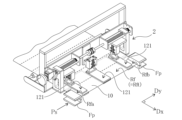
- FIG. 2(B) is a conceptual perspective view of the packaging film piece forming mechanism
- Figures 3(A) and 3(B) are oblique views of a chuck unit provided in the packaging film piece forming mechanism, where Figure 3(A) shows the chuck portion when closed and Figure 3(B) shows the chuck portion when open.
- FIGS. 4(A) and 4(B) are oblique views of the restraining unit provided in the packaging film piece forming mechanism, where Figure 4(A) shows the case where the plate is moved away from the stage portion, and Figure 4(B) shows the case where the plate is brought close to the stage portion.
- FIG. 5 is a front view of the packaging device, illustrating a case where the carry-in section and the carry-out section are separated from each other in a transport mechanism included in the packaging device.
- FIG. 6 is a conceptual diagram showing a first pressing unit and a second pressing unit of the attachment mechanism included in the packaging device, as viewed from the conveyance direction.
- FIG. 7(A) is a conceptual diagram showing the operation of the first pressing unit, FIG.
- FIG. 7(B) is a conceptual diagram showing the first stage of the operation of the second pressing unit
- FIG. 7(C) is a conceptual diagram showing the second stage of the operation of the second pressing unit.
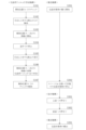
- FIG. 8 is a flowchart showing a control process executed by a control device provided in the packaging device.
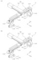
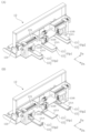
- FIG. 9A is a perspective view showing the sequence of operations of the packaging film piece forming mechanism.
- FIG. 9B is a perspective view showing the sequence of operations of the packaging film piece forming mechanism.
- FIG. 9C is a perspective view showing the sequence of operations of the packaging film piece forming mechanism.
- FIG. 9D is a perspective view showing the sequence of operations of the packaging film piece forming mechanism.
- FIG. 9E is a perspective view showing the sequence of operations of the packaging film piece forming mechanism.
- FIG. 9F is a perspective view showing the sequence of operations of the packaging film piece forming mechanism.
- FIGS. 1(A) and 1(B) are a front view and a block diagram conceptually illustrating a packaging device according to an embodiment.
- the packaging device includes a packaging film piece forming mechanism 1, a conveying mechanism 2, an attaching mechanism 3, and a control device 4.
- the configuration of each part will be specifically described below.
- Packaging Film Forming Mechanism Fig. 2(A) is a perspective view conceptually showing a strip of film 10 used in the packaging film forming mechanism 1 of this embodiment.
- the strip of film 10 is a long film in which a plurality of regions Rf are continuously connected via perforations Pm.
- each region Rf is an area that becomes a film piece (packaging film piece Qf) used to package an object to be packaged 20 (such as a food container; see Fig. 5).
- An adhesive is applied in advance to this strip of film 10 to enable the packaging film piece Qf to be attached to the object to be packaged 20.
- the adhesive is applied in a predetermined width along both end edges of the object to be packaged 20.
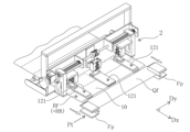
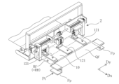
- FIG. 2(B) is a perspective view conceptually showing the packaging film piece forming mechanism 1.
- the packaging film piece forming mechanism 1 is a mechanism that enables the formation of packaging film pieces Qf using the above-mentioned strip film 10, starting from the leading region Rft (see FIG. 2(A)) at the leading end of the strip film 10 among the multiple regions Rf, and includes a chuck unit 11 and a restraining unit 12.
- the strip film 10 is wound around a core material in a roll shape (see FIG. 2(A)), for example, and is pulled out only by the pulling force of the chuck unit 11, which will be described below.
- the packaging device of this embodiment does not necessarily require a motor for unwinding the strip film 10.
- the strip film 10 is positioned so that it can be pulled out in the same direction as the conveying direction Dx of the packaged object 20 by the conveying mechanism 2, which will be described later.
- the packaging device is not limited to this, and may be modified as appropriate to include a motor that additionally unwinds the strip film 10 as the strip film 10 is pulled out.
- ⁇ Chuck unit> 3A and 3B are perspective views of the chuck unit 11.
- the chuck unit 11 includes a pair of chuck portions Fp and a slide transport portion Gp.
- each chuck portion Fp includes an upper chuck component 111 and a lower chuck component 112, and is configured to be able to open and close by moving these up and down in opposite directions.
- FIG. 3(A) shows the chuck portion Fp in a closed state
- FIG. 3(B) shows the chuck portion Fp in an open state.
- each chuck portion Fp the upper chuck component 111 is composed of an L-shaped block body with a tip protruding downward, and the lower chuck component 112 is composed of an L-shaped block body with a tip protruding upward.
- the tip surfaces (flat surfaces) of these block bodies are configured to come into surface contact with each other when the block bodies are closed.
- each chuck portion Fp is configured so that when the upper chuck component 111 and the lower chuck component 112 clamp the strip film 10, they can maintain the gripped state of the strip film 10 even if the strip film 10 is subsequently pulled by the movement described below; in other words, they are configured so that the strip film 10 does not slip out. More specifically, the force with which the strip film 10 is clamped and the frictional force of the tip surface are appropriately adjusted.
- the slide transport section Gp is configured to be able to move a pair of chuck sections Fp back and forth between a start position Ps (see Figures 1 and 9A) where chucking of the leading region Rft of the strip film 10 begins, and a release position Pt (see Figures 5 and 9F) located away from the start position Ps in a direction in which the strip film 10 can be pulled out (in this embodiment, in the same direction as the transport direction Dx) where the chucking of the leading region Rft is released.
- the slide transport section Gp includes a support section 113 that supports the pair of chuck sections Fp, and a guide section 114 that causes the pair of chuck sections Fp to reciprocate by sliding the support section 113.
- the guide section 114 specifies that the direction in which the support section 113 slides is the same as the transport direction Dx.
- the support portion 113 is composed of a beam portion 113A that extends in the width direction Dy and is slidably attached to the guide portion 114, and a pair of support arms 113B that support the pair of chuck portions Fp at a predetermined height position.
- the predetermined height position is a height position at which the strip film 10 can be passed between the upper chuck component 111 and the lower chuck component 112 when the support portion 113 is slid along the guide portion 114 with the chuck portions Fp open.
- the support portion 113 is configured so that the distance between the pair of chuck portions Fp can be adjusted. Specifically, the support portion 113 is configured so that the position of the pair of support arm portions 113B in the width direction Dy can be adjusted by the ball screw 113C. More specifically, the support portion 113 is configured so that the pair of support arm portions 113B can be moved in opposite directions to each other in the width direction Dy by manually turning the handle 113D to rotate the shaft portion of the ball screw 113C.
- the guide portion 114 incorporates a ball screw (not shown), and the shaft of the ball screw is rotated by a motor (not shown) to slide the support portion 113.
- the support portion 113 can be moved back and forth in the axial direction of the ball screw by controlling the rotation direction (forward and reverse directions) of the motor.
- the guide portion 114 is positioned so that the axial direction of the ball screw is the same as the transport direction Dx.
- the sliding range of the support portion 113 is defined so that the pair of chuck portions Fp can be moved back and forth between the start position Ps and the release position Pt described above.
- This sliding range may be defined by controlling the rotation of the motor, or may be defined by physically providing stoppers or the like at each of the positions that correspond to the start position Ps and the release position Pt.
- ⁇ Blocking unit> 4(A) and 4(B) are perspective views of the restraining unit 12.
- the restraining unit 12 is configured to clamp the film strip 10 and stop the pulling out of the film strip 10.
- the restraining unit 12 includes a pressing portion 121 that presses the film strip 10 from above, and a stage portion 122 that receives the pressing force of the pressing portion 121 on the underside of the film strip 10.
- the pressing unit 121 includes a plate 121A arranged such that its lower surface faces the upper surface of the stage unit 122, and a driving unit 121B (such as an actuator) that moves the plate 121A up and down.
- the pressing unit 121 is configured so that the driving unit 121B can selectively move the lower surface of the plate 121A away from the upper surface of the stage unit 122 (see FIG. 4A) and bring the lower surface of the plate 121A closer to the upper surface of the stage unit 122 (see FIG. 4B) by moving the plate 121A up and down.
- the lower surface of the plate 121A coming closer to the upper surface of the stage unit 122 means that when the plate 121A is lowered with the strip film 10 placed on the stage unit 122, the lower surface of the plate 121A comes into surface contact with the strip film 10 and presses the strip film 10 from above. In this way, by pressing the strip of film 10 from above with plate 121A, the strip of film 10 can be clamped between plate 121A and stage portion 122, and as a result, it becomes possible to stop the pulling out of the strip of film 10.
- the restraining unit 12 includes a first restraining portion Hp1 located in the center of the width direction Dy, and a pair of second restraining portions Hp2 located on both sides of the first restraining portion Hp1 in the width direction Dy, and each of these three restraining portions is composed of a pressing portion 121 and a stage portion 122.
- the restraining unit 12 is configured so that when the strip film 10 is clamped, both end portions Rfa and Rfb of the leading region Rft protrude from the restraining unit 12 (specifically, the pair of second restraining portions Hp2) to enable chucking by the pair of chuck portions Fp (see FIG. 9F).
- the braking unit 12 is configured so that the positions of the pair of second braking parts Hp2 in the width direction Dy can be adjusted by the ball screw 123 so that the positions of the outer edges of the pair of second braking parts Hp2 in the width direction Dy (specifically, the outer edges of the plate 121A and the stage part 122) can be adjusted. More specifically, the braking unit 12 is configured so that the pair of second braking parts Hp2 can be moved in opposite directions to each other in the width direction Dy by manually turning the handle 124 to rotate the shaft part of the ball screw 123.
- this packaging film piece forming mechanism 1 With this packaging film piece forming mechanism 1, the leading region Rft of the strip film 10 is chucked by a pair of chuck portions Fp, and the pair of chuck portions Fp is moved to the release position Pt to allow the strip film 10 to be pulled out. At the same time, the strip film 10 is clamped by the restraining unit 12 to prevent the strip film 10 from being pulled out. By performing both of these operations, tension can be generated in the strip film 10, and this tension can be used to tear off the leading region Rft of the strip film 10 at the perforation Pm at the boundary with the next region Rf. This makes it possible to form the packaging film piece Qf without using a cutting blade. The operation of the packaging film piece forming mechanism 1 when forming the packaging film piece Qf will be described in detail later.
- the conveying mechanism 2 is a mechanism for conveying the packaging objects 20 (such as food containers), and includes an inlet section 21 and an outlet section 22 that can move toward and away from each other in the conveying direction Dx (see Figs. 1(A) and 5). Both the inlet section 21 and the outlet section 22 are composed of devices such as conveyors that enable the conveying of the packaging objects 20.
- the conveying mechanism 2 is configured to be able to form a space Sw that the packaging objects 20 can straddle below the release position Pt by separating the inlet section 21 and the outlet section 22 as shown in Fig. 5.
- the attachment mechanism 3 is a mechanism for attaching the packaging film piece Qf formed by the packaging film piece forming mechanism 1 to the packaging object 20 transported by the transport mechanism 2, and is equipped with a first pressing unit 31 and a second pressing unit 32 (see Figures 1 (A) and 5).
- FIG. 6 is a conceptual diagram showing the first pressing unit 31 and the second pressing unit 32 as viewed from the conveying direction Dx.
- FIG. 7(A) is a conceptual diagram showing the operation of the first pressing unit 31, and FIG. 7(B) and FIG. 7(C) are conceptual diagrams showing the first and second stages, respectively, of the operation of the second pressing unit 32.
- the first pressing unit 31 is configured to be able to press the piece of packaging film Qf, which has been released from the chuck by the pair of chuck portions Fp at the release position Pt, against the top surface of the object to be packaged 20 (see FIG. 7A).
- the first pressing unit 31 includes a pressing arm portion 311 and a drive portion 312 (such as an actuator) that moves the pressing arm portion 311 up and down (see Figs. 1(A), 6, and 7(A)).
- the pressing arm portion 311 is positioned so that when it is lowered by the drive portion 312, it can press the center portion of the piece of packaging film Qf against the top surface of the object to be packaged 20 (see Fig. 7(A)).
- both ends Qfa and Qfb of the piece of packaging film Qf hang down (see Fig. 7(A)).
- the second pressing unit 32 is configured to be able to press both downwardly hanging ends Qfa and Qfb of the piece of packaging film Qf against the bottom surface of the object to be packaged 20 (see Figures 7(B) and 7(C)).
- the second pressing unit 32 includes a pair of pressing roll parts 321 and a drive part 322 (such as an actuator) that moves the pair of pressing roll parts 321 to the position of the bottom surface of the packaging object 20 (see Figs. 1(A), 6, 7(A) and 7(B)).
- the second pressing unit 32 is configured to reliably press both end parts Qfa and Qfb of the packaging film piece Qf against the bottom surface of the packaging object 20 while reducing the impact on the packaging object 20 by moving the pair of pressing roll parts 321 along an arc-shaped curve to the bottom surface of the packaging object 20 (see Figs. 7(B) and 7(C)).
- the second pressing unit 32 is also configured to move the pair of pressing roll parts 321 to the bottom surface of the packaging object 20 at different times. Specifically, the second pressing unit 32 can perform the following operations: first, move one pressing roll section 321 to press the end Qfa of the piece of packaging film Qf against the bottom surface of the object to be packaged 20 (see FIG. 7(B)), and then move the other pressing roll section 321 to press the end Qfb of the piece of packaging film Qf against the bottom surface of the object to be packaged 20 (see FIG. 7(C)).
- the second pressing unit 32 is not limited to a unit that moves the pair of pressing roll parts 321 along an arc-shaped curve, and may be modified as appropriate to a unit that moves the pair of pressing roll parts 321 horizontally to the bottom surface of the packaging object 20.
- the pressing roll part 321 may have a roll surface made of a cushioning material to cushion the impact when the packaging film piece Qf is pressed against the bottom surface of the packaging object 20.
- the first pressing unit 31 positions the center of the piece of packaging film Qf on the top surface of the object to be packaged 20, while the second pressing unit 32 smoothly guides both ends Qfa and Qfb of the piece of packaging film Qf to the bottom surface of the object to be packaged 20, making it possible to attach both ends Qfa and Qfb to the bottom surface of the object to be packaged 20.
- the control device 4 includes a storage unit 41 and a control unit 42 (see FIG. 1(B)).
- the storage unit 41 is a section that stores information necessary for controlling the packaging device (such as parameters necessary for controlling the packaging film piece forming mechanism 1, the conveying mechanism 2, and the attaching mechanism 3), and is composed of storage devices such as ROM and RAM.
- the control unit 42 is a section that executes control of the packaging device, and is composed of a processing device such as a CPU. Below, a specific description is given of the control processing executed by the control device 4 in the packaging device.
- FIG. 8 is a flow chart showing the control process executed by the control device 4. Also, FIGS. 9A to 9F are perspective views sequentially showing the operation of the packaging film piece forming mechanism 1 resulting from the control process.
- the control device 4 first controls the chuck unit 11 to move the pair of chuck portions Fp to the start position Ps and causes the pair of chuck portions Fp to chuck the leading region Rft of the strip film 10 (step S101, see FIG. 9A). At this time, the control device 4 controls the restraining unit 12 to cause the restraining unit 12 to maintain the leading region Rft of the strip film 10 in a clamped state. Specifically, the control device 4 causes the restraining unit 12 to maintain the pressing portion 121 in a lowered state, thereby maintaining the leading region Rft of the strip film 10 pressed by the pressing portion 121. This makes it possible to reliably prevent curling that is likely to occur in the leading region Rft of the strip film 10.
- step S101 the control device 4 controls the restraining unit 12 to cause the restraining unit 12 to release the clamping of the leading region Rft of the strip film 10 (step S102, see FIG. 9B). Specifically, the control device 4 raises the pressing portion 121 to release the pressing portion 121 from the pressing of the leading region Rft of the strip film 10. This releases the strip film 10 from the restraint exerted by the restraining unit 12, and as a result, the strip film 10 becomes available for pulling out in the transport direction Dx.
- step S102 the control device 4 controls the chuck unit 11 to cause the pair of chuck portions Fp to continue chucking the leading region Rft while starting to move the pair of chuck portions Fp from the start position Ps toward the release position Pt (step S103).
- the strip film 10 is pulled by the pair of chuck portions Fp and pulled out in the transport direction Dx (see FIG. 9C).
- step S103 the control device 4 controls the chuck unit 11 to temporarily stop the pair of chuck portions Fp in the middle of moving them to the release position Pt (step S104, see FIG. 9C). Specifically, the control device 4 temporarily stops the pair of chuck portions Fp when the entire perforation Pm at the boundary between the leading region Rft and the next region Rf chucked by the pair of chuck portions Fp moves outside the clamping range Rx that is the target of clamping by the restraining unit 12.
- step S104 the control device 4 controls the restraining unit 12 to clamp the next region Rf connected to the leading region Rft via the perforation Pm (step S105, see FIG. 9D). Specifically, the control device 4 lowers the pressing portion 121 to press the next region Rf. This causes the restraining unit 12 to stop the strip film 10 from being pulled out in the transport direction Dx.
- control device 4 controls the chuck unit 11 to resume the movement of the pair of chuck portions Fp to the release position Pt, and uses the instantaneous force generated when the movement resumes to tear off the leading region Rft of the strip film 10 at the perforation Pm at the boundary with the next region Rf (step S106; see FIG. 9E).
- the leading region Rft can be pulled by the pair of chuck portions Fp while the next region Rf adjacent to the leading region Rft is clamped to prevent the strip film 10 from being pulled out.
- the tension generated in the strip film 10 at that time can be used to tear off only the leading region Rft at the perforation Pm at the boundary with the next region Rf.
- the torn leading region Rft then becomes a single piece of packaging film Qf.
- an instantaneous force is generated by restarting the movement of the pair of chuck portions Fp, and by using this instantaneous force, it becomes easier to break the strip film 10 at the perforation Pm.
- step S106 the control device 4 controls the chuck unit 11 to cause the pair of chuck portions Fp to release the chuck from the piece of packaging film Qf when the pair of chuck portions Fp reach the release position Pt (step S107; see FIG. 9F). This releases the piece of packaging film Qf from the chuck held by the pair of chuck portions Fp.
- step S107 the control device 4 controls the transport mechanism 2 to start transporting the packaging object 20 (step S201), and transports the packaging object 20 to a position below the release position Pt and stops it (step S202). At this time, the control device 4 separates the transport section 21 and the transport section 22 to form a space Sw, and stops the packaging object 20 across the space Sw (see FIG. 5). This sets the packaging object 20 in a state (with the bottom surface exposed) in which the packaging film piece Qf can be wrapped by the attachment mechanism 3.
- control device 4 controls the attachment mechanism 3 to cause the first pressing unit 31 to press the center of the piece of packaging film Qf against the top surface of the packaging object 20 (step S301; see FIG. 7A). As a result, both ends Qfa and Qfb of the piece of packaging film Qf hang down.
- control device 4 controls the attachment mechanism 3 to cause the second pressing unit 32 to press both ends Qfa and Qfb of the piece of packaging film Qf against the bottom surface of the object to be packaged 20 (step S302; see Figures 7(B) and 7(C)). This causes both ends Qfa and Qfb to be attached to the bottom surface of the object to be packaged 20, thereby completing the attachment (packaging) of the piece of packaging film Qf to the object to be packaged 20.
- control device 4 controls the conveying mechanism 2 to bring the loading section 21 and the unloading section 22 close to each other, so that the packaged packaging target object 20 is placed on the unloading section 22 and unloaded (step S203).
- control device 4 returns to step S101 and step S201, and repeats the processes from step S101 and S201.
- This enables the packaging device to repeatedly and continuously perform the formation of the packaging film piece Qf and the attachment (packaging) of the packaging film piece Qf to the packaging object 20.
- the packaging film piece forming mechanism 1 of this embodiment can form the packaging film piece Qf without using a cutting blade. This allows for improved maintainability in the packaging film piece forming mechanism 1 and packaging device. Therefore, the above-described packaging film piece forming mechanism 1 and packaging device can achieve both improved maintainability and continuous operation.
- step S105 the control unit 12 clamps the next region Rf adjacent to the leading region Rft of the strip film 10, and then causes the control unit 12 to continue in that state until the control device 4 returns to step S101 and starts chucking the next region Rf (in other words, the new leading region Rft created by tearing off the leading region Rft).
- next region Rf continues to be clamped by the restraining unit 12 until it is chucked by the pair of chuck portions Fp after the leading region Rft is torn off to become the new leading region Rft. This makes it possible to reliably prevent curling that is likely to occur in the leading region Rft of the strip film 10.
- the packaging device described above the amount of the strip film 10 pulled out by the pair of chuck portions Fp and the size of the space Sw formed between the inlet portion 21 and the outlet portion 22 (the distance between the inlet portion 21 and the outlet portion 22) can be appropriately adjusted according to the length of the packaging film piece Qf to be formed (the length between adjacent perforations Pm). Therefore, the packaging device of this embodiment has a high degree of freedom in terms of the size and shape of the applicable packaging film piece Qf, and further the size and shape of the object 20 to be packaged.
- Packaging film piece forming mechanism 2 Conveying mechanism 3 Sticking mechanism 4
- Control device 10 Strip film 11
- Chuck unit 12 Restraining unit 20
- Packaging object 21 Carry-in section 22 Carry-out section 31
- First pressing unit 32 Second pressing unit 41
- Memory section 42 Control section Dx Conveying direction Dy Width direction Fp Chuck section Gp Slide conveying section Hp1 First restraining section Hp2 Second restraining section Pm Perforation Ps Start position Pt Release position Qf Packaging film piece Qfa, Qfb End Rf Region Rft Leading region Rfa, Rfb End Rx Clamping range Sw Space 111 Upper chuck component 112 Lower chuck component 113 Support section 113A Beam section 113B Support arm section 113C Ball screw 113D Handle 114 Guide section 121 Pressing section 121A Plate 121B Driving section 122 Stage section 123 Ball screw 124 Handle 311 Pressing arm section 312 Driving section 321 Pressing roll section 322 Driving section
Landscapes
- Engineering & Computer Science (AREA)
- Mechanical Engineering (AREA)
- Basic Packing Technique (AREA)
- Advancing Webs (AREA)
- Auxiliary Devices For And Details Of Packaging Control (AREA)
Abstract
Description
図1(A)及び図1(B)は、実施形態に係る包装装置を概念的に示した正面図及びブロック図である。これらの図に示されるように、包装装置は、包装用フィルム片形成機構1と、搬送機構2と、貼付機構3と、制御装置4と、を備える。以下、各部の構成について具体的に説明する。
図2(A)は、本実施形態の包装用フィルム片形成機構1で用いられる帯状フィルム10を概念的に示した斜視図である。この図に示されるように、帯状フィルム10は、複数の領域Rfがミシン目Pmを介して連続的に繋がった長尺状のフィルムである。ここで、各領域Rfは、包装対象物20(食品用容器など。図5参照)の包装に用いられるフィルム片(包装用フィルム片Qf)になる領域である。そして、この帯状フィルム10には、包装対象物20へ包装用フィルム片Qfの貼付けを可能にするための接着剤が予め塗布されている。例えば、包装対象物20の両端縁に沿って、接着剤が所定幅で塗布されている。
図3(A)及び図3(B)は、チャックユニット11の斜視図である。チャックユニット11は、一対のチャック部Fpと、スライド搬送部Gpと、を含む。
図4(A)及び図4(B)は、制止ユニット12の斜視図である。制止ユニット12は、帯状フィルム10を挟持して当該帯状フィルム10の引出しを停止させることが可能となるように構成されている。具体的には、制止ユニット12は、帯状フィルム10を上側から押圧する押圧部121と、当該押圧部121の押圧力を帯状フィルム10の下側で受けるステージ部122と、を含む。
搬送機構2は、包装対象物20(食品用容器など)を搬送するための機構であり、搬送方向Dxにおいて近接離間可能な搬入部21及び搬出部22を備える(図1(A)及び図5参照)。搬入部21及び搬出部22は何れも、コンベアなど、包装対象物20の搬送を可能にする装置で構成されている。そして、搬送機構2は、図5に示されるように搬入部21及び搬出部22を離間させることにより、解除位置Ptの下方の位置に、包装対象物20が跨ぐことができるスペースSwを形成することが可能となるように構成されている。
貼付機構3は、包装用フィルム片形成機構1によって形成された包装用フィルム片Qfを、搬送機構2で搬送されてくる包装対象物20に貼り付けるための機構であり、第1押当てユニット31と、第2押当てユニット32と、を備える(図1(A)及び図5参照)。
制御装置4は、記憶部41と制御部42とを備える(図1(B)参照)。記憶部41は、包装装置の制御に必要な情報(包装用フィルム片形成機構1、搬送機構2、貼付機構3の制御に必要なパラメータなど)が保存される部分であり、ROMやRAMなどの記憶デバイスで構成されている。制御部42は、包装装置の制御を実行する部分であり、CPUなどの処理デバイスで構成されている。以下、包装装置において制御装置4が実行する制御処理について具体的に説明する。
2 搬送機構
3 貼付機構
4 制御装置
10 帯状フィルム
11 チャックユニット
12 制止ユニット
20 包装対象物
21 搬入部
22 搬出部
31 第1押当てユニット
32 第2押当てユニット
41 記憶部
42 制御部
Dx 搬送方向
Dy 幅方向
Fp チャック部
Gp スライド搬送部
Hp1 第1制止部
Hp2 第2制止部
Pm ミシン目
Ps 開始位置
Pt 解除位置
Qf 包装用フィルム片
Qfa、Qfb 端部
Rf 領域
Rft 先頭領域
Rfa、Rfb 端部
Rx 挟持範囲
Sw スペース
111 上側チャック構成部
112 下側チャック構成部
113 支持部
113A 梁部
113B 支持アーム部
113C ボールネジ
113D ハンドル
114 ガイド部
121 押圧部
121A プレート
121B 駆動部
122 ステージ部
123 ボールネジ
124 ハンドル
311 押当てアーム部
312 駆動部
321 押当てロール部
322 駆動部
Claims (7)
- 複数の包装用フィルム片となる複数の領域がミシン目を介して連続的に繋がった帯状フィルムを用いて、当該複数の領域のうちの帯状フィルムの先頭にある先頭領域から前記包装用フィルム片を順に形成していくことを可能にする包装用フィルム片形成機構であり、
前記先頭領域の幅方向についての両端部をそれぞれチャックする一対のチャック部を含み、当該一対のチャック部を、前記先頭領域に対するチャックを開始する開始位置と、当該開始位置から前記帯状フィルムの引出しが可能な方向へ離間した位置であって前記先頭領域に対するチャックを解除する解除位置と、の間で往復移動させることが可能なチャックユニットと、
前記帯状フィルムを挟持して当該帯状フィルムの引出しを停止させることが可能な制止ユニットと、
を備える、包装用フィルム片形成機構。 - 前記制止ユニットは、前記帯状フィルムを挟持したときに、前記先頭領域の前記幅方向についての両端部が、当該制止ユニットからはみ出ることによって前記一対のチャック部によるチャックが可能な状態となるように構成されている、請求項1に記載の包装用フィルム片形成機構。
- 請求項1又は2に記載の包装用フィルム片形成機構と、
制御装置と、
を備える、包装装置であり、
前記制御装置は、
前記一対のチャック部に、前記帯状フィルムの先頭領域に対する前記開始位置でのチャックを実行させ、
前記先頭領域に対するチャックを前記一対のチャック部に継続させつつ、当該一対のチャック部を、前記開始位置から前記解除位置へ移動させ、
前記一対のチャック部を前記解除位置へ移動させる途中で、前記ミシン目を介して前記先頭領域に繋がっている次の領域を前記制止ユニットに挟持させる、包装装置。 - 前記制御装置は、
前記一対のチャック部を前記解除位置へ移動させる途中で、当該一対のチャック部にチャックさせている前記先頭領域と次の領域との境界にあるミシン目の全体が、前記制止ユニットによる挟持の対象になる挟持範囲の外へ出たときに、前記一対のチャック部を一旦停止させ、それから前記次の領域を制止ユニットに挟持させ、
その後、前記一対のチャック部の移動を再開させることにより、再開時に発生する瞬発力を利用して、前記帯状フィルムの先頭領域を、次の領域との境界にあるミシン目で引きちぎる、請求項3に記載の包装装置。 - 前記制御装置は、
前記一対のチャック部を前記解除位置へ移動させる途中で、当該一対のチャック部にチャックさせている前記先頭領域に連続する次の領域を前記制止ユニットに挟持させた後、その状態を、当該次の領域に対する前記一対のチャック部によるチャックが開始されるまで、当該制止ユニットに継続させる、請求項3又は4に記載の包装装置。 - 包装対象物を搬送する搬送機構と、
前記包装用フィルム片形成機構によって形成された包装用フィルム片を、前記搬送機構で搬送されてくる包装対象物に貼り付ける貼付機構と、
を更に備える、請求項3~5の何れかに記載の包装装置。 - 前記搬送機構は、搬送方向において近接離間可能な搬入部及び搬出部を備え、それらを離間させることにより、前記解除位置の下方の位置に、前記包装対象物が跨ぐことができるスペースを形成することが可能であり、
前記貼付機構は、
前記解除位置にて前記一対のチャック部によるチャックが解除された前記包装用フィルム片を、前記包装対象物の上面に押し当てて、当該包装用フィルム片の両端部が下へ垂れた状態にすることが可能な第1押当てユニットと、
前記包装用フィルム片のうちの下へ垂れた両端部を、前記包装対象物の底面に押し当てることが可能な第2押当てユニットと、
を備える、請求項6に記載の包装装置。
Priority Applications (4)
| Application Number | Priority Date | Filing Date | Title |
|---|---|---|---|
| JP2024552755A JP7621718B1 (ja) | 2023-06-01 | 2024-05-24 | 包装用フィルム片形成機構及び包装装置 |
| KR1020257036774A KR20250169267A (ko) | 2023-06-01 | 2024-05-24 | 포장용 필름편 형성 기구 및 포장 장치 |
| AU2024280342A AU2024280342A1 (en) | 2023-06-01 | 2024-05-24 | Packaging film piece formation mechanism and packaging device |
| CN202480036668.3A CN121219201A (zh) | 2023-06-01 | 2024-05-24 | 包装用膜片形成机构和包装装置 |
Applications Claiming Priority (2)
| Application Number | Priority Date | Filing Date | Title |
|---|---|---|---|
| JP2023090635 | 2023-06-01 | ||
| JP2023-090635 | 2023-06-01 |
Publications (1)
| Publication Number | Publication Date |
|---|---|
| WO2024247902A1 true WO2024247902A1 (ja) | 2024-12-05 |
Family
ID=93657545
Family Applications (1)
| Application Number | Title | Priority Date | Filing Date |
|---|---|---|---|
| PCT/JP2024/019135 Ceased WO2024247902A1 (ja) | 2023-06-01 | 2024-05-24 | 包装用フィルム片形成機構及び包装装置 |
Country Status (5)
| Country | Link |
|---|---|
| JP (1) | JP7621718B1 (ja) |
| KR (1) | KR20250169267A (ja) |
| CN (1) | CN121219201A (ja) |
| AU (1) | AU2024280342A1 (ja) |
| WO (1) | WO2024247902A1 (ja) |
Citations (3)
| Publication number | Priority date | Publication date | Assignee | Title |
|---|---|---|---|---|
| JPS63126356U (ja) * | 1987-02-09 | 1988-08-18 | ||
| JPH03226420A (ja) * | 1990-01-30 | 1991-10-07 | Matsuyama Plow Mfg Co Ltd | 野菜包装装置 |
| JPH07237615A (ja) * | 1994-02-28 | 1995-09-12 | Teraoka Seiko Co Ltd | ストレッチ包装方法及び包装機 |
Family Cites Families (1)
| Publication number | Priority date | Publication date | Assignee | Title |
|---|---|---|---|---|
| JP7374477B2 (ja) | 2020-01-23 | 2023-11-07 | エムケー技研株式会社 | 包装装置 |
-
2024
- 2024-05-24 AU AU2024280342A patent/AU2024280342A1/en active Pending
- 2024-05-24 WO PCT/JP2024/019135 patent/WO2024247902A1/ja not_active Ceased
- 2024-05-24 JP JP2024552755A patent/JP7621718B1/ja active Active
- 2024-05-24 KR KR1020257036774A patent/KR20250169267A/ko active Pending
- 2024-05-24 CN CN202480036668.3A patent/CN121219201A/zh active Pending
Patent Citations (3)
| Publication number | Priority date | Publication date | Assignee | Title |
|---|---|---|---|---|
| JPS63126356U (ja) * | 1987-02-09 | 1988-08-18 | ||
| JPH03226420A (ja) * | 1990-01-30 | 1991-10-07 | Matsuyama Plow Mfg Co Ltd | 野菜包装装置 |
| JPH07237615A (ja) * | 1994-02-28 | 1995-09-12 | Teraoka Seiko Co Ltd | ストレッチ包装方法及び包装機 |
Also Published As
| Publication number | Publication date |
|---|---|
| JP7621718B1 (ja) | 2025-01-27 |
| CN121219201A (zh) | 2025-12-26 |
| KR20250169267A (ko) | 2025-12-02 |
| AU2024280342A1 (en) | 2025-10-30 |
| JPWO2024247902A1 (ja) | 2024-12-05 |
Similar Documents
| Publication | Publication Date | Title |
|---|---|---|
| KR20080013976A (ko) | 외부 싸개를 가진 웨브재 롤의 제조방법과 장치 | |
| US6966961B2 (en) | Splicing device for splicing two web materials together, unwinder comprising said splicing device and relative method | |
| CN111356642B (zh) | 捆扎包装装置 | |
| JP7022022B2 (ja) | シート体の切断方法及びその切断装置 | |
| US20260109499A1 (en) | Packaging device and method for packaging discrete medicaments in pouches | |
| CN110216867B (zh) | 薄膜输送装置、薄膜输送方法以及薄膜粘贴装置 | |
| JPH02242709A (ja) | ラッピング方法及び装置 | |
| JP7621718B1 (ja) | 包装用フィルム片形成機構及び包装装置 | |
| KR20180046920A (ko) | 시트 박리 장치 및 박리 방법 | |
| CN107614144B (zh) | 带状板的接合方法 | |
| JP4953592B2 (ja) | 包装装置 | |
| JP4953391B2 (ja) | 冊子断裁装置 | |
| JP2003072725A (ja) | ラベル貼付装置 | |
| JP2782663B2 (ja) | 巻取紙の解梱仕立て方法及び装置 | |
| JP2009269639A (ja) | 帯掛け包装方法および装置 | |
| JP4823151B2 (ja) | 結束アームの原点位置設定機構 | |
| CN119858695B (zh) | 柔性包装材料全自动包装装置 | |
| JP7079554B2 (ja) | 包装材の包装装置及び包装方法 | |
| JPH10338212A (ja) | 包装装置 | |
| JP4824428B2 (ja) | 包装装置 | |
| JP7362311B2 (ja) | 把持装置 | |
| JP2002211800A (ja) | 平版印刷版束の搬送装置及び搬送方法 | |
| JP3351547B2 (ja) | 紙葉類処理装置の不要紙処理方法及びその方法を用いた開梱装置 | |
| JP2006327670A (ja) | 包装装置 | |
| JPH0632316A (ja) | 結束装置 |
Legal Events
| Date | Code | Title | Description |
|---|---|---|---|
| WWE | Wipo information: entry into national phase |
Ref document number: 2024552755 Country of ref document: JP |
|
| 121 | Ep: the epo has been informed by wipo that ep was designated in this application |
Ref document number: 24815386 Country of ref document: EP Kind code of ref document: A1 |
|
| WWE | Wipo information: entry into national phase |
Ref document number: AU2024280342 Country of ref document: AU |
|
| WWE | Wipo information: entry into national phase |
Ref document number: 2501007404 Country of ref document: TH |
|
| ENP | Entry into the national phase |
Ref document number: 2024280342 Country of ref document: AU Date of ref document: 20240524 Kind code of ref document: A |
|
| ENP | Entry into the national phase |
Ref document number: 1020257036774 Country of ref document: KR Free format text: ST27 STATUS EVENT CODE: A-0-1-A10-A15-NAP-PA0105 (AS PROVIDED BY THE NATIONAL OFFICE) |
|
| WWE | Wipo information: entry into national phase |
Ref document number: KR1020257036774 Country of ref document: KR |