WO2024252473A1 - Refrigeration cycle device - Google Patents
Refrigeration cycle device Download PDFInfo
- Publication number
- WO2024252473A1 WO2024252473A1 PCT/JP2023/020819 JP2023020819W WO2024252473A1 WO 2024252473 A1 WO2024252473 A1 WO 2024252473A1 JP 2023020819 W JP2023020819 W JP 2023020819W WO 2024252473 A1 WO2024252473 A1 WO 2024252473A1
- Authority
- WO
- WIPO (PCT)
- Prior art keywords
- heat
- heat source
- refrigerant
- heat exchanger
- heat medium
- Prior art date
- Legal status (The legal status is an assumption and is not a legal conclusion. Google has not performed a legal analysis and makes no representation as to the accuracy of the status listed.)
- Ceased
Links
Images









Classifications
-
- F—MECHANICAL ENGINEERING; LIGHTING; HEATING; WEAPONS; BLASTING
- F24—HEATING; RANGES; VENTILATING
- F24F—AIR-CONDITIONING; AIR-HUMIDIFICATION; VENTILATION; USE OF AIR CURRENTS FOR SCREENING
- F24F11/00—Control or safety arrangements
- F24F11/70—Control systems characterised by their outputs; Constructional details thereof
- F24F11/80—Control systems characterised by their outputs; Constructional details thereof for controlling the temperature of the supplied air
- F24F11/87—Control systems characterised by their outputs; Constructional details thereof for controlling the temperature of the supplied air by controlling absorption or discharge of heat in outdoor units
-
- F—MECHANICAL ENGINEERING; LIGHTING; HEATING; WEAPONS; BLASTING
- F25—REFRIGERATION OR COOLING; COMBINED HEATING AND REFRIGERATION SYSTEMS; HEAT PUMP SYSTEMS; MANUFACTURE OR STORAGE OF ICE; LIQUEFACTION SOLIDIFICATION OF GASES
- F25B—REFRIGERATION MACHINES, PLANTS OR SYSTEMS; COMBINED HEATING AND REFRIGERATION SYSTEMS; HEAT PUMP SYSTEMS
- F25B1/00—Compression machines, plants or systems with non-reversible cycle
-
- F—MECHANICAL ENGINEERING; LIGHTING; HEATING; WEAPONS; BLASTING
- F25—REFRIGERATION OR COOLING; COMBINED HEATING AND REFRIGERATION SYSTEMS; HEAT PUMP SYSTEMS; MANUFACTURE OR STORAGE OF ICE; LIQUEFACTION SOLIDIFICATION OF GASES
- F25B—REFRIGERATION MACHINES, PLANTS OR SYSTEMS; COMBINED HEATING AND REFRIGERATION SYSTEMS; HEAT PUMP SYSTEMS
- F25B27/00—Machines, plants or systems, using particular sources of energy
-
- F—MECHANICAL ENGINEERING; LIGHTING; HEATING; WEAPONS; BLASTING
- F25—REFRIGERATION OR COOLING; COMBINED HEATING AND REFRIGERATION SYSTEMS; HEAT PUMP SYSTEMS; MANUFACTURE OR STORAGE OF ICE; LIQUEFACTION SOLIDIFICATION OF GASES
- F25B—REFRIGERATION MACHINES, PLANTS OR SYSTEMS; COMBINED HEATING AND REFRIGERATION SYSTEMS; HEAT PUMP SYSTEMS
- F25B29/00—Combined heating and refrigeration systems, e.g. operating alternately or simultaneously
-
- F—MECHANICAL ENGINEERING; LIGHTING; HEATING; WEAPONS; BLASTING
- F25—REFRIGERATION OR COOLING; COMBINED HEATING AND REFRIGERATION SYSTEMS; HEAT PUMP SYSTEMS; MANUFACTURE OR STORAGE OF ICE; LIQUEFACTION SOLIDIFICATION OF GASES
- F25B—REFRIGERATION MACHINES, PLANTS OR SYSTEMS; COMBINED HEATING AND REFRIGERATION SYSTEMS; HEAT PUMP SYSTEMS
- F25B30/00—Heat pumps
- F25B30/06—Heat pumps characterised by the source of low potential heat
Definitions
- This disclosure relates to a refrigeration cycle device capable of multiple operations such as cooling, heating, and hot water supply, and in particular to a refrigeration cycle device that can reduce the load on the heat source side heat exchanger by using unused heat as a heat source.
- the refrigeration cycle device disclosed in Patent Document 1 includes a heat source unit, a relay unit connected to the heat source unit by a high-pressure side connection pipe and a low-pressure side connection pipe, and a user side unit including an indoor unit and a hot water heat source circuit.
- the relay unit has a first distribution section and a second distribution section that are configured so that two connection pipes extending from each user side unit can be selectively connected to the high-pressure side connection pipe or the low-pressure side connection pipe.
- the first distribution section switches the connection between one connection pipe of each user side unit and the high-pressure side connection pipe or the low-pressure side connection pipe, so that each user side unit can individually perform heating operation, cooling operation, or hot water supply operation.
- the refrigeration cycle device of Patent Document 1 balances the cooling load, heating load, and hot water load of multiple user units, improving the efficiency of the entire system.
- Patent Document 2 air conditioning systems that use melted snow water or well water are known from the past (see, for example, Patent Document 2).
- the snow and ice air conditioning system disclosed in Patent Document 2 comprises an indirect outdoor air cooling machine, a compression refrigeration cooling machine, and a snow and ice air conditioning machine.
- the snow and ice air conditioning machine uses the cold energy of the snowy mountains to cool a refrigerant, which then cools the outdoor air supplied to the heat exchangers on the heat source side of the indirect outdoor air cooling machine and the compression refrigeration cooling machine.
- the snow and ice air conditioning system of Patent Document 2 makes effective use of the cold energy of the snowy mountains, enabling energy-saving operation.
- the refrigeration cycle device disclosed in Patent Document 1 can improve the COP by balancing the cooling load, heating load, and hot water load of the user unit, but the heating and cooling capacity required for the load in the corresponding usage situation of the user unit is borne by the heat source unit. Therefore, no further energy saving effect beyond the improvement of the COP of the refrigeration cycle device can be expected.
- the snow and ice air conditioning system disclosed in Patent Document 2 can use the cold energy of snowy mountains to reduce the load on the indirect outdoor air cooler and the compression refrigeration cooler, but the refrigerant circuits of the indirect outdoor air cooler, the compression refrigeration cooler, and the snow and ice cooler are independent.
- the snow and ice cooler supplies cooled outdoor air to the sensible heat exchanger of the indirect outdoor air cooler and the condenser of the compression refrigeration cooler, and the refrigerant circuits of the indirect outdoor air cooler and the compression refrigeration cooler are also independent, making it difficult to improve the efficiency of the entire system by balancing the load on the two coolers.
- This disclosure has been made to solve the problems described above, and provides a refrigeration cycle device that improves COP by balancing the load between each user unit, and enables energy-saving operation of the entire system by utilizing an external heat source.
- the refrigeration cycle device includes a heat source machine having a compressor for compressing a refrigerant, a heat source side heat exchanger, and a first flow path switching device for switching the flow path of the refrigerant, a high-pressure side pipe through which the refrigerant flows out of the heat source machine, a low-pressure side pipe through which the refrigerant flows into the heat source machine, a utilization side unit connected to the high-pressure side pipe and the low-pressure side pipe and having a utilization side heat exchanger and a first flow control device for controlling the flow rate of the refrigerant flowing to the utilization side heat exchanger, and a utilization side unit connected to the high-pressure side pipe and the low-pressure side pipe.
- a heat medium relay unit having an intermediate heat exchanger for exchanging heat between the refrigerant and a heat medium carrying heat from an external heat source and a second flow control device for controlling a flow rate of the refrigerant flowing through the intermediate heat exchanger; a first branch unit for branching the high-pressure side piping and the low-pressure side piping to the user side unit and the heat medium relay unit, respectively, and connected to a first connection piping extending from the user side unit and the heat medium relay unit; and a second branch unit for branching the high-pressure side piping and the low-pressure side piping to the user side unit and the heat medium relay unit, respectively, and connected to a second connection piping extending from the user side unit and the heat medium relay unit.
- the first flow switching device is configured to connect the refrigerant so that it flows from the discharge side of the compressor through the heat source side heat exchanger to the high-pressure side pipe and from the low-pressure side pipe to the suction side of the compressor when the heat source side heat exchanger functions as a condenser, and to connect the refrigerant so that it flows from the discharge side of the compressor to the high-pressure side pipe and from the low-pressure side pipe to the suction side of the compressor through the heat source side heat exchanger when the heat source side heat exchanger functions as an evaporator
- the first branching section is configured to switch the connection between the first connection pipe and the high-pressure side pipe or the low-pressure side pipe
- the second flow switching device is configured so that the heat medium heat exchanger can function as an auxiliary condenser when the heat source side heat exchanger functions as a condenser, and the heat medium heat exchanger can function as an auxiliary evaporator when the heat source side heat exchanger functions as an evaporator.
- the heat medium converter can function to supplement the capacity of the heat source side heat exchanger. Since the heat medium converter is configured to exchange heat with the refrigerant of the refrigeration cycle device using an external heat source such as well water or geothermal heat, and part or all of the capacity of the heat source side heat exchanger can be supplemented by the external heat source, the refrigeration cycle device can be operated in a more energy-efficient manner than before.
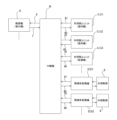
- FIG. 1 is a schematic diagram of a configuration of a refrigeration cycle device 100 according to a first embodiment.
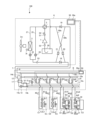
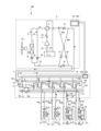
- 1 is an example of a circuit diagram showing a refrigeration cycle device 100 according to a first embodiment.
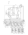
- 3 is an explanatory diagram of a flow of a refrigerant when the refrigeration cycle apparatus 100 according to the first embodiment is performing a cooling operation.
- FIG. FIG. 4 is a diagram showing usage states of heat medium relay units D1, D2 based on temperatures T, t1, and t2 of various parts of the refrigeration cycle apparatus 100 according to the first embodiment.
- 3 is an explanatory diagram of a flow of a refrigerant when the refrigeration cycle apparatus 100 according to the first embodiment is performing a cooling-dominant operation.
- FIG. 3 is an explanatory diagram of a flow of a refrigerant when the refrigeration cycle apparatus 100 according to the first embodiment is performing a heating operation.
- FIG. 3 is an explanatory diagram of a flow of a refrigerant when the refrigeration cycle apparatus 100 according to the first embodiment is performing a heating-dominant operation.
- FIG. 4 is a flowchart showing an operation of the refrigeration cycle apparatus 100 according to the first embodiment.
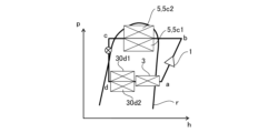
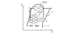
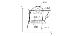
- FIG. 2 is a Mollier diagram of the refrigeration cycle apparatus 100 according to the first embodiment during cooling operation.
- FIG. 2 is a Mollier diagram of the refrigeration cycle apparatus 100 according to the first embodiment during cooling operation.
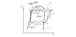
- FIG. 2 is a Mollier diagram of the refrigeration cycle apparatus 100 according to the first embodiment during cooling-dominant operation.
- FIG. 1 is an explanatory diagram of a flow of a refrigerant when the refrigeration cycle apparatus 100 according to the first embodiment is performing a heating-dominant operation.
- FIG. 4 is a flowchart showing an operation of the refrigeration cycle apparatus 100
- FIG. 11 is an example of a circuit diagram showing a refrigeration cycle device 200 according to a second embodiment.
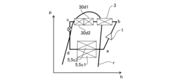
- FIG. FIG. 11 is a Mollier diagram during heating operation of the refrigeration cycle apparatus 200 according to the second embodiment.
- 11 is an example of a circuit diagram showing a refrigeration cycle device 200 according to a second embodiment.
- FIG. 11 is a Mollier diagram of the refrigeration cycle apparatus 200 according to the second embodiment during heating-dominated operation.
- the user side unit C is, for example, an indoor air conditioner or water heater, and is supplied with refrigerant from the repeater B to perform indoor air conditioning or water heating through a refrigeration cycle.
- Each user side unit C is connected in series to the repeater B and in parallel with each other. In FIG. 1, three user side units C are connected to the repeater B, but this number is not limited, and two or more user side units C may be installed, or there may be only one.
- the user side unit C can be an indoor unit of an air conditioner, a water heater, a refrigerator, etc., and there is no limit to the equipment that can be connected.
- the heat medium converter D is further connected to the relay unit B.
- the heat medium converter D is connected to the relay unit B and is connected in a circuit configuration similar to that of the user unit C.
- the heat medium converter D also receives refrigerant from the relay unit B, like the user unit C.
- the heat medium converter D is further connected to an external heat source E.
- the external heat source E and the heat medium converter D are connected by a circuit in which a heat medium different from the refrigerant flowing from the relay unit B circulates.
- the external heat source E connected to the heat medium converter D has heat or cold, such as well water, geothermal heat, or sunlight.
- the heat medium converter D is a device that transfers the heat or cold of the external heat source E to a refrigerant via a heat medium.
- the external heat source E is well water
- the well water is pumped up and circulated as a heat medium through the heat medium circulation circuit 34 (see FIG. 2).
- geothermal heat is used as the external heat source E
- a heat medium such as water heated by geothermal heat circulates through the heat medium circulation circuit 34.
- sunlight is used as the external heat source E
- a heat medium such as water heated by sunlight circulates through the heat medium circulation circuit 34.
- Other examples of the external heat source E include ice and snow, melted snow, etc.
- the external heat source E can also be unused heat such as heat from river water, exhaust gas from equipment, wastewater, and waste heat generated by equipment.
- the heat medium, such as water, circulating through the heat medium circulation circuit 34 is heat exchanged with the refrigerant circulating through the heat source unit A, etc., in the heat medium heat exchanger 30 (see FIG. 2).
- FIG. 1 multiple heat transfer devices D and external heat sources E are installed, but a single one may be used. In addition, multiple types of heat sources may be used as the external heat source E.
- Whether the heat medium converter D is used as an evaporator or a condenser is determined based on whether the temperature of the external heat source E is high or low, based on the evaporation temperature and condensation temperature of the refrigerant in the refrigeration cycle that circulates through the heat source unit A, relay unit B, user unit C, and heat medium converter D.
- the heat medium converter D is used as an evaporator
- the heat medium converter D is used as a condenser.
- the heat medium converter D when a relatively high-temperature external heat source E such as geothermal energy or sunlight is used, the heat medium converter D should be used as an evaporator, and when a relatively low-temperature external heat source E such as well water, snow and ice, or melted snow is used, the heat medium converter D should be used as a condenser.
- a relatively high-temperature external heat source E such as geothermal energy or sunlight
- a relatively low-temperature external heat source E such as well water, snow and ice, or melted snow
- the heat medium converter D switches between using the first connection pipe 40 as an evaporator by directly connecting it to the low-pressure side pipe 6, and using the first connection pipe 40 as a condenser by directly connecting it to the high-pressure side pipe 7. Switching of operation using the heat medium converter D is performed by the second flow path switching device 10c (see Figure 2) provided in the relay unit B.
- Figure 1 shows, as an example, a case where the topmost user side unit C1 is in heating operation, the second user side unit C2 from the top is in cooling operation, and the third user side unit from the top is in water boiling operation.
- circuit configuration of refrigeration cycle device 100 is an example of a circuit diagram showing the refrigeration cycle apparatus 100 according to the first embodiment.
- the heat source unit A and the relay unit B are connected by a low-pressure side pipe 6 and a high-pressure side pipe 7.
- the high-pressure side pipe 7 is a pipe through which the high-pressure refrigerant compressed by the compressor 1 flows out, either directly or via the heat source side heat exchanger 3.
- the low-pressure side pipe 6 is a pipe through which the low-pressure refrigerant that has passed through the user side unit C or the heat medium converter D flows in, and is a pipe for returning the refrigerant from the relay unit B to the heat source unit A.
- the refrigerant in the high-pressure side pipe 7 flows into the high-pressure side branch 10a of the first branch 10 of the relay unit B.
- the refrigerant in the high-pressure side branch 10a flows into the user unit C or the heat medium converter D by opening the high-pressure side solenoid valves 9c1, 9c2, 9d1, and 9d2 provided in the first branch 10.
- the high-pressure side solenoid valves 9c1, 9c2, 9d1, and 9d2 may be collectively referred to as the high-pressure side solenoid valves 9.
- the low-pressure side pipe 6 is connected to the low-pressure side branch 10b of the first branch 10 of the relay unit B.
- the refrigerant from the user side unit C or the heat medium converter D flows into the low-pressure side branch 10b by opening the low-pressure side solenoid valves 8c1, 8c2, 8d1, and 8d2.
- the low-pressure side solenoid valves 8c1, 8c2, 8d1, and 8d2 may be collectively referred to as the low-pressure side solenoid valves 8.
- the low-pressure side solenoid valve 8 and the high-pressure side solenoid valve 9 are connected to first connection pipes 40c1, 40c2, 40d1, and 40d2, which are one of the pipes extending from the utilization side unit C and the heat medium converter D, respectively.
- the first connection pipes 40c1, 40c2, 40d1, and 40d2 may be collectively referred to as the first connection pipes 40.
- the other pipes extending from the user unit C and the heat medium converter D are called second connection pipes 41c1, 41c2, 41d1, and 41d2.
- the second connection pipes 41c1, 41c2, 41d1, and 41d2 are connected to the second branch 11 of the relay unit.
- the second connection pipes 41c1, 41c2, 41d1, and 41d2 may be collectively called second connection pipes 41.
- the refrigerant flows from the second branch section 11 to the user side unit C and the heat medium converter D, respectively, or flows from the user side unit C and the heat medium converter D to the second branch section 11.
- the refrigerant flows from the high pressure side branch 10a connected to the high pressure side pipe 7 through the high pressure side solenoid valve 9 into the user side unit C or the heat medium converter D, and the refrigerant that has passed through the user side unit C or the heat medium converter D flows into the second branch 11.
- refrigerant that has passed through another user unit C, another heat medium converter D, or refrigerant that has been separated from the high-pressure side piping 7 by the gas-liquid separator 12 and passed through the first heat exchanger 17 and the second heat exchanger 16 flows from the second branch 11 into the user unit C or the heat medium converter D.
- the refrigerant that has passed through the user unit C or the heat medium converter D passes through the low-pressure side solenoid valve 8 and flows from the low-pressure side branch 10b into the low-pressure side piping 6.
- the first heat exchanger 17 and the second heat exchanger 16 are sometimes referred to as internal heat exchangers.
- the relay unit B switches the connection state of the utilization side unit C or the heat medium converter D by switching the opening and closing of the low pressure side solenoid valve 8 and the high pressure side solenoid valve 9 of the first branch section 10. This switching allows the utilization side heat exchanger 5 of the utilization side unit C and the heat medium converter 30 of the heat medium converter D to switch between functioning as an evaporator or a condenser, respectively.
- the first branching section 10 branches the high-pressure side pipe 7 and the low-pressure side pipe 6 for each of the user side units C and the heat medium converters D, and connects them to the first connection pipe 40, which is one of the pipes extending from each of the user side units C and the heat medium converters D.
- the first branching section 10 controls whether the first connection pipe 40 of the user side units C and the heat medium converters D is connected to the high-pressure side pipe 7 or the low-pressure side pipe 6 by controlling the high-pressure side solenoid valve 9 and the low-pressure side solenoid valve 8 to close one and open the other.
- the low-pressure side solenoid valve 8 and the high-pressure side solenoid valve 9 of the first branching section 10 may be collectively referred to as the second flow path switching device 10c.
- the second flow path switching device 10c includes the high-pressure side solenoid valve 9 and the low-pressure side solenoid valve 8 provided for each of the user side units C and the heat medium converters D, but is not limited to this form and may be configured as a three-way valve to which the high-pressure side pipe 7, the low-pressure side pipe, and the first connection pipe 40 are connected, for example.
- the heat source unit A is usually placed in a space such as a rooftop outside a building, and supplies cold or hot heat to the user units C1 and C2 via the relay unit B.
- the heat source unit A is not limited to being placed outdoors, and may be placed in an enclosed space such as a machine room with a ventilation opening.
- the heat source unit A may also be placed inside a building if the waste heat can be exhausted to the outside of the building through an exhaust duct.
- the heat source unit A may be placed inside a building as a water-cooled outdoor unit.
- the heat source unit A incorporates a compressor 1, a first flow path switching device 2 that switches the refrigerant flow direction of the heat source unit A, a heat source side heat exchanger 3, and an accumulator 29.
- the compressor 1, the first flow path switching device 2, the heat source side heat exchanger 3, and the accumulator 29 are connected by a low pressure side pipe 6 and a high pressure side pipe 7.
- the heat source side heat exchanger 3 is connected in series with the first flow control device 22.
- a bypass pipe 25 having a second flow control device 26 is connected in parallel with the heat source side heat exchanger 3.
- the second flow control device 26 can adjust the flow rate to adjust the amount of refrigerant that bypasses the heat source side heat exchanger 3.
- an outdoor flow control device 3m is installed near the heat source side heat exchanger 3 to control the flow rate of a fluid such as outdoor air.
- the outdoor air is sent to the heat source side heat exchanger 3 by the outdoor flow control device 3m, and heat exchange with the refrigerant is performed.
- the outdoor flow control device 3m is, for example, a fan that sends outdoor air to the heat source side heat exchanger 3.
- an air-cooled outdoor heat exchanger is used as an example of the heat source side heat exchanger 3
- an outdoor fan is used as an example of the outdoor flow control device 3m.
- the heat source side heat exchanger 3 may be a water-cooled outdoor heat exchanger or the like as long as the refrigerant exchanges heat with another fluid.
- a pump is used as the outdoor flow control device 3m.
- a heat medium such as outdoor air that exchanges heat with the refrigerant in the heat source side heat exchanger 3 may be referred to as a heat source heat medium. Note that, although the first embodiment illustrates a case in which there is one heat source side heat exchanger 3, multiple heat source side heat exchangers 3 may be provided.
- the heat source unit A is also provided with a first connection pipe 60a, a second connection pipe 60b, a check valve 18, a check valve 19, a check valve 20, and a check valve 21.
- the first connection pipe 60a, the second connection pipe 60b, the check valve 18, the check valve 19, the check valve 20, and the check valve 21 allow high-pressure refrigerant to flow out of the heat source unit A via the high-pressure side pipe 7.
- the first connection pipe 60a, the second connection pipe 60b, the check valve 18, the check valve 19, the check valve 20, and the check valve 21 allow low-pressure refrigerant to flow into the heat source unit A via the low-pressure side pipe 6.
- Compressor 1 draws in the refrigerant and compresses it to a high-temperature, high-pressure state, and is composed of, for example, an inverter compressor with a capacity controllable.
- the first flow path switching device 2 switches between the flow of refrigerant during heating operation and the flow of refrigerant during cooling operation.
- the first flow path switching device 2 switches between two connection states. In one connection state, the first pipe 27 and the bypass pipe 25 are connected to the discharge side of the compressor 1, and the low-pressure side pipe 6 is connected to an accumulator 29 provided on the suction side of the compressor 1.
- the first pipe 27 is installed in parallel with the bypass pipe 25 and is a pipe leading to the heat source side heat exchanger 3.
- the first pipe 27 and the bypass pipe 25 are connected to the accumulator 29 provided on the suction side of the compressor 1, and the discharge side of the compressor 1 is directly connected to the high-pressure side pipe 7.
- the first flow path switching device 2 is exemplified as a four-way switching valve.
- the heat source side heat exchanger 3 functions as an evaporator during heating operation and as a condenser or radiator during cooling operation.
- the heat source side heat exchanger 3 exchanges heat between the refrigerant and the outdoor air, evaporating and gasifying the refrigerant or condensing and liquefying the refrigerant.
- the outdoor flow control device 3m forms an air passage for the air flowing to the heat source side heat exchanger 3.
- the accumulator 29 is provided on the suction side of the compressor 1, and stores surplus refrigerant due to differences between heating and cooling operations or surplus refrigerant due to transient changes in operation. Note that, although the first embodiment illustrates a case in which one heat source side heat exchanger 3 is provided, multiple heat source side heat exchangers 3 may be connected in parallel.
- the check valve 18 is connected to the high-pressure side pipe 7 between the heat source side heat exchanger 3 and the relay unit B, and allows the refrigerant to flow only in the direction from the heat source unit A to the relay unit B.
- the check valve 19 is provided in the low-pressure side pipe 6 between the relay unit B and the first flow path switching device 2, and allows the refrigerant to flow only in the direction from the relay unit B to the heat source unit A.
- the check valve 20 is provided in the first connection pipe 60a, and allows the refrigerant discharged from the compressor 1 to flow to the relay unit B during heating operation.
- the check valve 21 is provided in the second connection pipe 60b, and allows the refrigerant returning from the relay unit B to flow to the suction side of the compressor 1 via the heat source side heat exchanger 3 or the bypass pipe 25 during heating operation.
- the first connection pipe 60a connects the low-pressure side pipe 6 between the first flow switching device 2 and the check valve 19 in the heat source unit A, and the high-pressure side pipe 7 between the check valve 18 and the relay unit B.
- the second connection pipe 60b connects the low-pressure side pipe 6 between the check valve 19 and the relay unit B in the heat source unit A, and the high-pressure side pipe 7 between the heat source side heat exchanger 3 and the check valve 18.
- the heat source unit A may also be provided with a discharge pressure gauge 51, a suction pressure gauge 52, a medium pressure pressure gauge 53, and a thermometer 54.
- the discharge pressure gauge 51 is provided on the discharge side of the compressor 1 and measures the pressure of the refrigerant discharged from the compressor 1.
- the suction pressure gauge 52 is provided on the suction side of the compressor 1 and measures the pressure of the refrigerant sucked into the compressor 1.
- the medium pressure pressure gauge 53 is provided upstream of the check valve 18 and measures the medium pressure, which is the pressure of the refrigerant upstream of the check valve 18.
- the thermometer 54 is provided on the discharge side of the compressor 1 and measures the temperature of the refrigerant discharged from the compressor 1.
- the pressure information and temperature information detected by the discharge pressure gauge 51, the suction pressure gauge 52, the medium pressure pressure gauge 53, and the thermometer 54 are sent to the control device 50 that controls the operation of the refrigeration cycle device 100, and are used to control each actuator.
- the bypass pipe 25 bypasses the heat source side heat exchanger 3.
- the second flow control device 26 is provided midway through the bypass pipe 25 and is configured to be freely opened and closed, and controls the flow rate of the refrigerant flowing through the bypass pipe 25.
- the second flow control device 26 adjusts the flow rate of the refrigerant flowing into the heat source side heat exchanger 3.
- the second flow control device 26 is configured so that the flow path resistance changes continuously.
- the relay unit B incorporates a first branching section 10, a second branching section 11, a gas-liquid separator 12, a first bypass pipe 14a, a second bypass pipe 14b, a third flow control device 13, a fourth flow control device 15, a first heat exchanger 17, a second heat exchanger 16, and a control device 50.
- the control device 50 has the same configuration and function as the control device 50 of the heat source unit A.
- the first branching section 10 branches the refrigerant flowing in the high-pressure side pipe 7 to the user side unit C and the heat medium converter D.
- the first branching section 10 also merges the refrigerant flowing in the user side unit C and the heat medium converter D and allows it to flow into the low-pressure side pipe 6.
- the first branching section 10 includes a low-pressure side solenoid valve 8 and a high-pressure side solenoid valve 9 installed in the first connection pipe 40 of the user side unit C and the heat medium converter D.
- the first connection pipe 40 of the user side unit C and the heat medium converter D is branched at the first branching section 10, one of which is connected to the low-pressure side pipe 6 via the low-pressure side solenoid valve 8, and the other of which is connected to the high-pressure side pipe 7 via the high-pressure side solenoid valve 9.
- the low-pressure side solenoid valve 8 and the high-pressure side solenoid valve 9 are controlled to open and close, so that the first connection pipe 40 of the user side unit C and the heat medium converter D can be switched to connect to either the low-pressure side pipe 6 or the high-pressure side pipe 7.
- the low-pressure side solenoid valve 8 and the high-pressure side solenoid valve 9 provided in the relay unit B are collectively referred to as the second flow path switching device 10c.
- the low-pressure side solenoid valve 8 and the high-pressure side solenoid valve 9 are installed in each pipe where the first connection pipe 40 is branched into two, but they may be configured using, for example, a three-way valve.
- first connection pipe 40 of the user side unit C and the heat medium converter D is configured to connect to either the low-pressure side pipe 6 or the high-pressure side pipe 7.
- the low-pressure side solenoid valve 8 and the high-pressure side solenoid valve 9 are preferably configured to be closed so that the refrigerant does not flow to any of the user side units C and the heat medium converters D.
- the second branch section 11 branches the refrigerant flowing in the first bypass pipe 14a to the user unit C and the heat medium converter D.
- the second branch section 11 also merges the refrigerant flowing in the user unit C and the heat medium converter D and causes it to flow into the second bypass pipe 14b.
- the second branch section 11 has a junction between the first bypass pipe 14a and the second bypass pipe 14b.
- the gas-liquid separator 12 is provided midway through the high-pressure side pipe 7, and separates the refrigerant that flows in through the high-pressure side pipe 7 into gas and liquid.
- the gas phase portion separated by the gas-liquid separator 12 flows to the first branch section 10, and the liquid phase portion separated by the gas-liquid separator 12 flows to the second branch section 11.
- the user side units C are installed at positions where they can supply conditioned air to a space to be air-conditioned, such as a room, and supply cooled air or heated air to the space to be air-conditioned by using cold or hot heat from the heat source unit A supplied via the relay unit B.
- the user side units C1 and C2 each have a built-in user side heat exchanger 5c1, 5c2 and a first flow control device 4c1, 4c2.
- Each of the utilization side heat exchangers 5c1 and 5c2 exchanges heat between the air supplied from the flow control device 5m and the refrigerant to generate heated air or cooled air to be supplied to the space to be air-conditioned.
- the flow control device 5m forms an air path for the air flowing through the utilization side heat exchangers 5c1 and 5c2.
- the first flow control devices 4c1 and 4c2 are provided between the second branching section 11 of the relay unit B and the utilization side heat exchanger 5c1 or 5c2, and are configured to be freely opened and closed.
- the first flow control device 4c1 and the first flow control device 4c2 adjust the flow rate of the refrigerant flowing into the utilization side heat exchangers 5c1 and 5c2.
- the heat medium relay unit D is for supplying heat or cold from an external heat source E to a refrigerant circulating in the refrigeration cycle apparatus 100.
- the heat medium relay unit D incorporates an inter-heat medium heat exchanger 30 that exchanges heat between the refrigerant circulating in the heat source unit A, the relay unit B, and the user side unit C and a heat medium that carries heat from the external heat source E, and second flow control devices 4d1 and 4d2 that control the flow rate of the refrigerant circulating in the inter-heat medium heat exchanger 30.
- the second flow control devices 4d1 and 4d2 are provided between the second branching section 11 of the relay unit B and the inter-heat medium heat exchanger 30d1 or 30d2, and are configured to be freely opened and closed.
- the second flow control devices 4d1 and 4d2 adjust the flow rate of the refrigerant flowing into the inter-heat medium heat exchangers 30d1 and 30d2.
- the heat medium is circulated through the heat medium circulation circuit 34 by the pump 31 and sent from the external heat source E to the heat medium-intermediate heat exchanger 30.
- the heat medium-intermediate heat exchanger 30 is, for example, a plate-type heat exchanger, inside which the refrigerant and heat medium circulate, and the heat or cold of the heat medium is transferred to the refrigerant.
- the heat medium converter D is equipped with external heat source temperature sensors 32 and 33.
- the external heat source temperature sensor 32 detects the temperature of the heat medium flowing into the heat medium heat exchanger 30.
- the external heat source temperature sensor 33 detects the temperature of the heat medium flowing out of the heat medium heat exchanger 30.
- those connected to external heat sources E with different temperatures may be referred to as a first heat medium converter and a second heat medium converter, respectively.
- the heat medium circulation circuit 34 may be configured to circulate an independent heat medium in the heat medium circulation circuit 34. As shown in FIG. 2, the heat medium circulation circuit 34 may be connected to an external heat exchanger F that exchanges heat between the external heat source E and the heat medium flowing through the heat medium circulation circuit 34. The external heat exchanger F exchanges heat between the heat medium and the external heat source E. The heat medium that has been heat exchanged in the external heat exchanger F is sent to the heat medium-to-heat medium heat exchanger 30 and is heat exchanged with the refrigerant circulating through the refrigerant circuit of the refrigeration cycle device 100.
- the quality of the heat medium flowing through the heat medium circulation circuit 34 can be maintained, and the durability of the heat medium circulation circuit 34 and the heat medium converter D can be ensured, as opposed to pumping up well water as the heat medium, for example.
- the configuration of the heat medium circulation circuit 34 may be changed as appropriate depending on what is used as the external heat source E.
- the refrigeration cycle device 100 makes effective use of such an external heat source E to achieve energy savings.
- the heat medium converters D1 and D2 can be installed in parallel on the relay unit B, so that multiple external heat sources E can be used for the refrigeration cycle device 100.
- the heat source side heat exchanger 3 functions as a condenser
- the heat medium converter D1 using the well water as the external heat source E1 also functions as a condenser, so that the capacity of the heat source side heat exchanger 3 during cooling operation or cooling-dominated operation can be supplemented by the heat medium converter D1.
- the heat source side heat exchanger 3 functions as an evaporator
- the heat medium converter D2 using sunlight as the external heat source E2 also functions as an evaporator, so that the capacity of the heat source side heat exchanger 3 during heating operation or heating-dominated operation can be supplemented by the heat medium converter D2.
- the refrigeration cycle apparatus 100 can appropriately select the operating state of the multiple user side units C from cooling, heating, and water heating operation by switching the connection between the heat source unit A and the user side units C using the second flow path switching device 10c, thereby enabling simultaneous cooling and heating operation.
- the refrigeration cycle apparatus 100 can appropriately switch the external heat source E to be used as an auxiliary for the heat source side heat exchanger 3 or as a substitute for the heat source side heat exchanger 3 by switching the connection state with the multiple heat medium converters D using the second flow path switching device 10c.
- the refrigeration cycle apparatus 100 is provided with a control device 50.
- the control device 50 controls actuators and the like based on refrigerant pressure information, refrigerant and heat medium temperature information, outdoor temperature information, indoor temperature information, and the like detected by each sensor provided in the refrigeration cycle apparatus 100.
- the control device 50 controls driving of the compressor 1, switching between the first flow path switching device 2 and the second flow path switching device 10c, driving of the fan motor of the outdoor flow control device 3m, driving of the fan motor of the flow control device 5m, and the pump 31 that sends the heat medium to the heat source side heat exchanger 3.
- the control device 50 controls the opening of the first flow control device 22, the second flow control device 26, the third flow control device 13, and the fourth flow control device 15.
- the control device 50 includes a memory 50a in which information for determining each control value is stored.
- the control device 50 may be configured with hardware such as a control circuit that realizes its functions.
- the control device 50 may be configured with a software program stored in a storage unit such as a semiconductor memory, and a computing device such as a microcomputer or a CPU (central processing unit) that executes the software program.
- the control device 50 is provided in the heat source unit A and the relay unit B, but the number of control devices 50 may be one or three or more.
- the control device 50 may be provided in the user unit C or the heat medium converter D, or may be provided as a separate unit in a location other than the heat source unit A, the relay unit B, the user unit C, and the heat medium converter D.
- the operation modes of the refrigeration cycle apparatus 100 include four modes: cooling operation, heating operation, cooling-dominated operation, and heating-dominated operation.
- Cooling operation is an operation mode in which all user side units C are in cooling operation or stopped.
- Heating operation is an operation mode in which all user side units C are in heating operation or stopped.
- Cooling-dominated operation is an operation mode in which heating or cooling can be selected for each indoor unit, and the cooling load is greater than the heating load.
- Cooling-dominated operation is an operation mode in which the heat source side heat exchanger 3 is connected to the discharge side of the compressor 1 and acts as a condenser.
- Heating-dominated operation is an operation mode in which heating or cooling can be selected for each indoor unit, and the heating load is greater than the cooling load.
- Heating-dominated operation is an operation mode in which the heat source side heat exchanger 3 is connected to the suction side of the compressor 1 and acts as an evaporator.
- (Cooling operation) 3 is an explanatory diagram of the flow of refrigerant when the refrigeration cycle apparatus 100 according to the first embodiment is in cooling operation. A case of cooling operation in which all of the user side units C1 and C2 perform cooling will be described.
- the control device 50 switches the first flow path switching device 2 so that the refrigerant discharged from the compressor 1 flows to the heat source side heat exchanger 3.
- the low pressure side solenoid valves 8c1 and 8c2 connected to the user side units C1 and C2 are opened, and the high pressure side solenoid valves 9c1 and 9c2 are closed.
- compressor 1 starts operating.
- the low-temperature, low-pressure gaseous refrigerant is compressed by compressor 1 and discharged as high-temperature, high-pressure gaseous refrigerant.
- the high-temperature, high-pressure gaseous refrigerant discharged from compressor 1 flows into heat source side heat exchanger 3 via first flow switching device 2.
- the refrigerant is cooled while heating the outdoor air, becoming medium-temperature, high-pressure liquid refrigerant or gas-liquid two-phase refrigerant.
- the medium-temperature, high-pressure refrigerant flowing out of heat source side heat exchanger 3 passes through high-pressure side piping 7 and is separated in gas-liquid separation device 12.
- the liquid refrigerant separated by the gas-liquid separator 12 passes through the first bypass pipe 14a, exchanges heat with the refrigerant flowing through the second bypass pipe 14b in the first heat exchanger 17, passes through the third flow control device 13, exchanges heat with the refrigerant flowing through the second bypass pipe 14b in the second heat exchanger 16, is cooled, and flows into the second branch section 11.
- a portion of the refrigerant that flows into the second branch 11 is bypassed to the second bypass piping 14b, and the remainder flows into the second connecting piping 41c1, 41c2 of the user side units C1, C2.
- the high-pressure liquid or gas-liquid two-phase refrigerant branched at the second branch 11 flows through the second connecting piping 41c1, 41c2 and flows into the first flow control devices 4c1, 4c2 of the user side units C1, C2.
- the high-pressure liquid refrigerant is then throttled and expanded by the first flow control devices 4c1, 4c2, reducing the pressure and becoming a low-temperature, low-pressure, two-phase gas-liquid state.
- the change in the refrigerant at the first flow control devices 4c1, 4c2 is carried out under a constant enthalpy.
- the low-temperature, low-pressure, two-phase gas-liquid refrigerant that flows out of the first flow control devices 4c1, 4c2 flows into the user side heat exchangers 5c1, 5c2.
- the refrigerant then heats up while cooling the indoor air, becoming a low-temperature, low-pressure gaseous refrigerant.
- the low-temperature, low-pressure gaseous refrigerant flowing out of the user-side heat exchangers 5c1 and 5c2 passes through the low-pressure solenoid valves 8c1 and 8c2, respectively, and flows into the low-pressure branch 10b of the first branch 10.
- the low-temperature, low-pressure gaseous refrigerant that joins in the low-pressure branch 10b also joins with the low-temperature, low-pressure gaseous refrigerant that has been heated in the first heat exchanger 17 and the second heat exchanger 16 of the second bypass piping 14b, passes through the low-pressure piping 6 and the first flow switching device 2, and flows into the compressor 1, where it is compressed.
- the heat medium relays D1, D2 When the heat medium relays D1, D2 are connected to the refrigeration cycle device 100, it is determined whether or not to use the heat medium relays D1, D2 based on the magnitude relationship between the temperatures t1, t2 of the external heat sources E1, E2 and the temperature T flowing into the heat source side heat exchanger 3.
- the external heat source temperature sensor 32 that measures the temperatures t1, t2 of the external heat sources E1, E2
- the one installed in one of the heat medium relays D1 and D2 may be referred to as the first external heat source temperature sensor, and the other may be referred to as the second external heat source temperature sensor.
- the temperature T is the temperature of the outside air sent to the heat source side heat exchanger 3
- the temperature t1 is the temperature of the heat medium flowing into the heat medium heat exchanger 30d1 of the heat medium converter D1
- the temperature t2 is the temperature of the heat medium flowing into the heat medium heat exchanger 30d2 of the heat medium converter D2.
- the heat medium converters D1 and D2 are used when the heat medium temperatures t1 and t2 are lower than the temperature T of the outside air flowing into the heat source side heat exchanger 3.
- the temperature T is measured by a temperature sensor 3t installed near the heat source side heat exchanger 3.
- the temperature t1 is measured by an external heat source temperature sensor 32 installed upstream of the heat medium heat exchanger 30d1 of the heat medium circulation circuit 34 of the heat medium converter D1.
- Temperature t2 is measured by an external heat source temperature sensor 32 installed upstream of the intermediate heat exchanger 30d2 in the heat medium circulation circuit 34 of the heat medium converter D2.
- FIG. 3 shows the flow of the refrigerant in the case of No. 1 or No. 2 in FIG. 4.
- the temperatures t1 and t2 of the heat medium are lower than the temperature T of the outside air flowing into the heat source side heat exchanger 3.
- the refrigeration cycle device 100 uses both the heat medium converters D1 and D2 to assist the heat source side heat exchanger 3, which is a condenser.
- FIG 20 is a Mollier diagram of the refrigeration cycle apparatus 200 according to embodiment 2 during heating operation.
- the utilization side heat exchangers 5c1 and 5c2 are connected so that the refrigerant flowing out from the discharge side (high pressure side) of the compressor 1 flows in through the high pressure side branch 10a.
- the utilization side heat exchangers 5c1 and 5c2 function as condensers, and the utilization side units C1 and C2 perform heating operation.
- the refrigerant flowing out of the utilization side heat exchangers 5c1 and 5c2 is decompressed by the first flow control devices 4c1 and 4c2 and flows into the second branch 11.
Landscapes
- Engineering & Computer Science (AREA)
- Physics & Mathematics (AREA)
- Mechanical Engineering (AREA)
- Thermal Sciences (AREA)
- General Engineering & Computer Science (AREA)
- Chemical & Material Sciences (AREA)
- Combustion & Propulsion (AREA)
- Other Air-Conditioning Systems (AREA)
Abstract
Description
本開示は、冷房運転、暖房運転及び給湯運転などの複合的な運転が可能な冷凍サイクル装置において、特に未利用熱を熱源として利用して熱源側熱交換器の負荷を低減できる冷凍サイクル装置に関する。 This disclosure relates to a refrigeration cycle device capable of multiple operations such as cooling, heating, and hot water supply, and in particular to a refrigeration cycle device that can reduce the load on the heat source side heat exchanger by using unused heat as a heat source.
従来から、空調給湯複合システムを含め、冷房負荷、暖房負荷及び給湯負荷を同時に供給できる空調給湯複合システムにおいては、冷房負荷、暖房負荷および給湯負荷をバランスさせることによりシステムCOPが向上することが知られている(例えば特許文献1参照)。特許文献1に開示されている冷凍サイクル装置は、熱源ユニットと、高圧側接続配管及び低圧側接続配管により熱源ユニットと接続された中継機と、室内ユニット及び給湯用熱源回路を含む利用側ユニットと、を備える。中継機は、各利用側ユニットから延びる2つの接続配管が、高圧側接続配管又は低圧側接続配管に選択的に接続できるように構成された第1分配部及び第2分配部を有している。特許文献1においては、第1分配部において、各利用側ユニットの一方の接続配管と高圧側接続配管又は低圧側接続配管との接続を切り替えることにより、各利用側ユニットのそれぞれが、暖房運転、冷房運転、又は給湯運転を個別に行うことができる。特許文献1の冷凍サイクル装置は、複数の利用側ユニットの冷房負荷、暖房負荷及び給湯負荷をバランスさせて、システム全体の効率が向上する。
It has been known that in air conditioning and hot water combined systems that can simultaneously supply cooling loads, heating loads, and hot water loads, including air conditioning and hot water combined systems, the system COP can be improved by balancing the cooling load, heating load, and hot water load (see, for example, Patent Document 1). The refrigeration cycle device disclosed in
また、従来から融雪水または井水などを利用した空調システムが知られている(例えば特許文献2参照)。特許文献2に開示されている雪氷利用空調システムは、間接外気利用冷房機と圧縮冷凍冷房機と雪氷冷房機とを備えている。雪氷冷房機は、雪山の冷熱を利用して冷媒を冷却し、その冷媒により間接外気利用冷房機及び圧縮冷凍冷房機の熱源側の熱交換器に供給する外気を冷却している。特許文献2の雪氷利用空調システムは、雪山の冷熱の有効利用が可能となり、省エネ運転が可能となる。
Furthermore, air conditioning systems that use melted snow water or well water are known from the past (see, for example, Patent Document 2). The snow and ice air conditioning system disclosed in
特許文献1に開示された冷凍サイクル装置は、利用側ユニットの冷房負荷、暖房負荷及び給湯負荷をバランスさせてCOPの向上が可能だが、利用側ユニットの当該使用状況における負荷に必要な冷暖房能力は熱源ユニットが負担する。そのため、冷凍サイクル装置のCOPの向上以上のさらなる省エネ効果は見込めなかった。
The refrigeration cycle device disclosed in
また、特許文献2に開示された雪氷空調システムは、雪山の冷熱を使用して間接外気利用冷房機及び圧縮冷凍冷房機の負荷を下げることが可能であるが、間接外気利用冷房機、圧縮冷凍冷房機及び雪氷冷房機のそれぞれの冷媒回路が独立している。雪氷冷房機は、冷却した外気を間接外気利用冷房機の顕熱交換器及び圧縮冷凍冷房機の凝縮器に供給するものであり、間接外気利用冷房機及び圧縮冷凍冷房機の冷媒回路も独立しているため、2つの冷房機の負荷のバランスによりシステム全体の効率化を図るのは困難であった。
The snow and ice air conditioning system disclosed in
本開示は、上記のような課題を解決するためになされたもので、各利用側ユニット間の負荷のバランスによりCOPを向上させるとともに、外部の熱源を利用してシステム全体の省エネ運転を可能とする、冷凍サイクル装置を提供するものである。 This disclosure has been made to solve the problems described above, and provides a refrigeration cycle device that improves COP by balancing the load between each user unit, and enables energy-saving operation of the entire system by utilizing an external heat source.
本開示に係る冷凍サイクル装置は、冷媒を圧縮する圧縮機、熱源側熱交換器、及び前記冷媒の流路を切り替える第1流路切替装置を有する熱源機と、前記熱源機から流出する前記冷媒が流れる高圧側配管と、前記熱源機へ流入する前記冷媒が流れる低圧側配管と、前記高圧側配管及び前記低圧側配管に接続され、利用側熱交換器及び前記利用側熱交換器に流れる前記冷媒の流量を制御する第1流量制御装置を有する利用側ユニットと、前記高圧側配管及び前記低圧側配管に接続され、外部熱源からの熱を運ぶ熱媒体と前記冷媒とを熱交換する熱媒体間熱交換器及び前記熱媒体間熱交換器に流れる前記冷媒の流量を制御する第2流量制御装置を有する熱媒体変換機と、前記高圧側配管及び前記低圧側配管のそれぞれを前記利用側ユニット及び前記熱媒体変換機に分岐し、前記利用側ユニット及び前記熱媒体変換機のそれぞれから延びる第1接続配管に接続された第1分岐部と、前記利用側ユニット及び前記熱媒体変換機のそれぞれから延びる第2接続配管と接続された第2分岐部と、を備え、前記第1流路切替装置は、前記熱源側熱交換器が凝縮器として機能する場合に、前記圧縮機の吐出側から前記熱源側熱交換器を経て前記高圧側配管に前記冷媒が流れるように接続し、かつ前記低圧側配管から前記圧縮機の吸入側に前記冷媒が流れるように接続し、前記熱源側熱交換器が蒸発器として機能する場合に、前記圧縮機の吐出側から前記高圧側配管に前記冷媒が流れるように接続し、かつ前記低圧側配管から前記熱源側熱交換器を経て前記圧縮機の吸入側に前記冷媒が流れる様に接続するように構成され、前記第1分岐部は、前記第1接続配管と前記高圧側配管又は前記低圧側配管との接続を切り替える第2流路切替装置を備え、前記第2流路切替装置は、前記熱源側熱交換器が凝縮器として機能する場合に前記熱媒体間熱交換器が補助凝縮器として機能することが可能なように、前記熱源側熱交換器が蒸発器として機能する場合には前記熱媒体間熱交換器が補助蒸発器として機能することが可能なように構成されている。 The refrigeration cycle device according to the present disclosure includes a heat source machine having a compressor for compressing a refrigerant, a heat source side heat exchanger, and a first flow path switching device for switching the flow path of the refrigerant, a high-pressure side pipe through which the refrigerant flows out of the heat source machine, a low-pressure side pipe through which the refrigerant flows into the heat source machine, a utilization side unit connected to the high-pressure side pipe and the low-pressure side pipe and having a utilization side heat exchanger and a first flow control device for controlling the flow rate of the refrigerant flowing to the utilization side heat exchanger, and a utilization side unit connected to the high-pressure side pipe and the low-pressure side pipe. a heat medium relay unit having an intermediate heat exchanger for exchanging heat between the refrigerant and a heat medium carrying heat from an external heat source and a second flow control device for controlling a flow rate of the refrigerant flowing through the intermediate heat exchanger; a first branch unit for branching the high-pressure side piping and the low-pressure side piping to the user side unit and the heat medium relay unit, respectively, and connected to a first connection piping extending from the user side unit and the heat medium relay unit; and a second branch unit for branching the high-pressure side piping and the low-pressure side piping to the user side unit and the heat medium relay unit, respectively, and connected to a second connection piping extending from the user side unit and the heat medium relay unit. and a second branching section, the first flow switching device is configured to connect the refrigerant so that it flows from the discharge side of the compressor through the heat source side heat exchanger to the high-pressure side pipe and from the low-pressure side pipe to the suction side of the compressor when the heat source side heat exchanger functions as a condenser, and to connect the refrigerant so that it flows from the discharge side of the compressor to the high-pressure side pipe and from the low-pressure side pipe to the suction side of the compressor through the heat source side heat exchanger when the heat source side heat exchanger functions as an evaporator, and the first branching section is configured to switch the connection between the first connection pipe and the high-pressure side pipe or the low-pressure side pipe, and the second flow switching device is configured so that the heat medium heat exchanger can function as an auxiliary condenser when the heat source side heat exchanger functions as a condenser, and the heat medium heat exchanger can function as an auxiliary evaporator when the heat source side heat exchanger functions as an evaporator.
本開示によれば、第1分岐部及び第2分岐部により各利用ユニット及び熱媒体変換機の熱源側熱交換器に対する接続を切り替えることにより、冷暖同時運転及び給湯運転を同時にできると共に熱媒体変換機が熱源側熱交換器の能力を補助するように機能させることができる。熱媒体変換機が例えば井水又は地熱などの外部熱源を利用して冷凍サイクル装置の冷媒との熱交換を行う様に構成され、熱源側熱交換器の能力の一部又は全部を外部熱源により補うことができるため、冷凍サイクル装置は、従来と比較して省エネ運転が可能となる。 According to the present disclosure, by switching the connection of each utilization unit and the heat source side heat exchanger of the heat medium converter using the first branch section and the second branch section, simultaneous heating and cooling operation and hot water supply operation can be performed simultaneously, and the heat medium converter can function to supplement the capacity of the heat source side heat exchanger. Since the heat medium converter is configured to exchange heat with the refrigerant of the refrigeration cycle device using an external heat source such as well water or geothermal heat, and part or all of the capacity of the heat source side heat exchanger can be supplemented by the external heat source, the refrigeration cycle device can be operated in a more energy-efficient manner than before.
実施の形態1.
以下、本開示に係る空気調和装置の実施の形態について、図面を参照しながら説明する。図1は、実施の形態1に係る冷凍サイクル装置100の構成の概略図である。図1に示すように、冷凍サイクル装置100は、熱源機Aと、熱源機Aに低圧側配管6及び高圧側配管7により接続された中継機Bと、中継機Bに第1接続配管40及び第2接続配管41により接続された利用側ユニットCを備える。利用側ユニットCは、冷凍サイクルを利用することによって、冷房運転、暖房運転又は給湯運転が選択できる。冷凍サイクル装置100が複数の利用側ユニットCを備える場合には、複数の利用側ユニットCのそれぞれは、冷房運転、暖房運転及び給湯運転から1つの運転モードを自由に選択し、運転が実施できる。つまり、冷凍サイクル装置100は、冷房運転及び暖房運転を同時に行う冷暖混在運転、さらに湯沸かし運転も混在した運転が可能である。
Hereinafter, an embodiment of an air conditioner according to the present disclosure will be described with reference to the drawings. FIG. 1 is a schematic diagram of a configuration of a
熱源機Aと中継機Bとは低圧側配管6及び高圧側配管7により接続され、熱源機Aが備える圧縮機1(図2参照)で圧縮された冷媒を中継機Bに送り、中継機Bが各利用側ユニットCに冷媒を分配する様に構成されている。各利用側ユニットCは、第1接続配管40及び第2接続配管41を、低圧側配管6及び高圧側配管7のうち何れかに連通させるかにより、運転状態が変更されるものである。図1は、一例として、1番上の利用側ユニットC1が暖房運転、上から2番目の利用側ユニットC2が冷房運転、上から3番目の利用側ユニットC3が湯沸かし運転を行っている場合を示している。
The heat source unit A and the relay unit B are connected by low-
利用側ユニットCは、例えば室内の空気調和装置又は給湯機などであり、中継機Bから冷媒が供給され、冷凍サイクルにより室内の空調又は湯沸かし等を行うものである。各利用側ユニットCは、中継機Bに対し直列に接続され、互いに並列に接続されている。図1において、3台の利用側ユニットCが中継機Bに接続されているが、台数を限定するものではなく、利用側ユニットCは2つ又はさらに多く設置されていても良いし、単数であっても良い。また、利用側ユニットCは、空気調和装置の室内機、給湯機又は冷凍機などを選択でき、接続できる機器を限定するものではない。 The user side unit C is, for example, an indoor air conditioner or water heater, and is supplied with refrigerant from the repeater B to perform indoor air conditioning or water heating through a refrigeration cycle. Each user side unit C is connected in series to the repeater B and in parallel with each other. In FIG. 1, three user side units C are connected to the repeater B, but this number is not limited, and two or more user side units C may be installed, or there may be only one. In addition, the user side unit C can be an indoor unit of an air conditioner, a water heater, a refrigerator, etc., and there is no limit to the equipment that can be connected.
利用側ユニットCは、低圧側配管6と直接接続させた場合に利用側熱交換器5(図2参照)が蒸発器として機能し冷房運転が行われ、高圧側配管7と直接接続させた場合に利用側熱交換器5が凝縮器として機能し暖房運転又は湯沸かし運転が行われる。各利用側ユニットCの運転の切り替えは、中継機Bが備える第2流路切替装置10c(図2参照)により行われる。
When the user side unit C is directly connected to the low
中継機Bには、さらに熱媒体変換機Dが接続されている。熱媒体変換機Dは、中継機Bに接続されており、利用側ユニットCと同様な回路構成で接続されている。熱媒体変換機Dも、利用側ユニットCと同様に中継機Bから冷媒が流入する。熱媒体変換機Dは、更に外部熱源Eと接続されている。外部熱源Eと熱媒体変換機Dとは、中継機Bから流入する冷媒とは異なる熱媒体が循環する回路により接続されている。熱媒体変換機Dは、外部熱源Eからの熱を有する熱媒体と熱源機Aから中継機Bを経て熱媒体変換機Dに流れ込んだ冷媒との間で熱交換を行い、外部熱源Eからの熱又は冷熱を冷媒に伝達することにより、凝縮器又は蒸発器として機能するように構成されている。なお、熱媒体変換機Dは、外部熱源Eが有する井水などの液体を熱媒体循環回路34(図2参照)に循環させるように構成させても良いし、熱媒体循環回路34に独立した熱媒体を循環させるように構成されていても良い。
The heat medium converter D is further connected to the relay unit B. The heat medium converter D is connected to the relay unit B and is connected in a circuit configuration similar to that of the user unit C. The heat medium converter D also receives refrigerant from the relay unit B, like the user unit C. The heat medium converter D is further connected to an external heat source E. The external heat source E and the heat medium converter D are connected by a circuit in which a heat medium different from the refrigerant flowing from the relay unit B circulates. The heat medium converter D is configured to exchange heat between the heat medium having heat from the external heat source E and the refrigerant that has flowed into the heat medium converter D from the heat source unit A via the relay unit B, and to function as a condenser or evaporator by transferring heat or cold from the external heat source E to the refrigerant. The heat medium converter D may be configured to circulate liquid such as well water from the external heat source E to the heat medium circulation circuit 34 (see FIG. 2), or may be configured to circulate an independent heat medium to the heat
特に、実施の形態1においては、熱媒体変換機Dは、熱源機Aが有する熱源側熱交換器3(図2参照)を補助するように機能し、熱源側熱交換器3が凝縮器として機能する場合には凝縮器として、熱源側熱交換器3が蒸発器として機能する場合には蒸発器として機能させることができる。これにより、熱源側熱交換器3は、外部熱源Eを利用した分だけ熱交換能力を落とした運転が可能となり、冷凍サイクル装置100全体として省エネルギー化が図れる。
In particular, in the first embodiment, the heat medium converter D functions to assist the heat source side heat exchanger 3 (see FIG. 2) of the heat source unit A, and can function as a condenser when the heat source
熱媒体変換機Dに接続されている外部熱源Eは、例えば井水、地熱、太陽光などの熱又は冷熱を有するものである。熱媒体変換機Dは、外部熱源Eが有する熱又は冷熱を、熱媒体を介して冷媒に伝達する装置である。外部熱源Eが井水である場合、その井水をくみ上げ、井水を熱媒体として熱媒体循環回路34(図2参照)に循環させる。また、外部熱源Eとして地熱を利用する場合、地熱により加熱された水などの熱媒体が熱媒体循環回路34を循環する。また、外部熱源Eとして太陽光を利用する場合は、太陽光により熱せられた水などの熱媒体が熱媒体循環回路34に循環する。その他、外部熱源Eとして氷雪又は融雪水などを利用しても良い。また、外部熱源Eとしては、河川の水が持つ熱、設備からの排ガス、排水、設備が発する廃熱などの未利用熱を利用することもできる。熱媒体循環回路34を循環する水などの熱媒体は、熱媒体間熱交換器30(図2参照)において熱源機Aなどを循環する冷媒と熱交換される。
The external heat source E connected to the heat medium converter D has heat or cold, such as well water, geothermal heat, or sunlight. The heat medium converter D is a device that transfers the heat or cold of the external heat source E to a refrigerant via a heat medium. When the external heat source E is well water, the well water is pumped up and circulated as a heat medium through the heat medium circulation circuit 34 (see FIG. 2). When geothermal heat is used as the external heat source E, a heat medium such as water heated by geothermal heat circulates through the heat
図1において熱媒体変換機D及び外部熱源Eは、複数設置されているが、単数でも良い。また、外部熱源Eは、複数種の熱源を利用しても良い。 In FIG. 1, multiple heat transfer devices D and external heat sources E are installed, but a single one may be used. In addition, multiple types of heat sources may be used as the external heat source E.
熱源機A、中継機B、利用側ユニットC及び熱媒体変換機Dを循環する冷凍サイクルの冷媒の蒸発温度及び凝縮温度を基準にして外部熱源Eの温度が高いか低いかにより、熱媒体変換機Dが蒸発器として用いられるか凝縮器に用いられるかが決まる。外部熱源Eの温度が冷媒の蒸発温度より高い場合は、熱媒体変換機Dは蒸発器として用いられ、外部熱源Eの温度が冷媒の凝縮温度よりも低い場合は、熱媒体変換機Dは凝縮器として用いられる。一般に、地熱又は太陽光などの比較的温度の高い外部熱源Eとして用いる場合は、熱媒体変換機Dを蒸発器として用い、井水、氷雪、融雪水などの比較的温度の低い外部熱源Eを用いる場合は、熱媒体変換機Dを凝縮器として用いると良い。 Whether the heat medium converter D is used as an evaporator or a condenser is determined based on whether the temperature of the external heat source E is high or low, based on the evaporation temperature and condensation temperature of the refrigerant in the refrigeration cycle that circulates through the heat source unit A, relay unit B, user unit C, and heat medium converter D. When the temperature of the external heat source E is higher than the evaporation temperature of the refrigerant, the heat medium converter D is used as an evaporator, and when the temperature of the external heat source E is lower than the condensation temperature of the refrigerant, the heat medium converter D is used as a condenser. In general, when a relatively high-temperature external heat source E such as geothermal energy or sunlight is used, the heat medium converter D should be used as an evaporator, and when a relatively low-temperature external heat source E such as well water, snow and ice, or melted snow is used, the heat medium converter D should be used as a condenser.
熱媒体変換機Dは、外部熱源Eの温度に応じて、第1接続配管40を低圧側配管6と直接接続させて蒸発器として用いるか、第1接続配管40を高圧側配管7と直接接続させて凝縮器として用いるかを切り替える。熱媒体変換機Dを使用した運転の切り替えは、中継機Bが備える第2流路切替装置10c(図2参照)により行われる。図1は、一例として、1番上の利用側ユニットC1が暖房運転、上から2番目の利用側ユニットC2が冷房運転、上から3番目の利用側ユニットが湯沸かし運転を行っている場合を示している。
Depending on the temperature of the external heat source E, the heat medium converter D switches between using the
(冷凍サイクル装置100の回路構成)
図2は、実施の形態1に係る冷凍サイクル装置100を示す回路図の一例である。熱源機Aと中継機Bとは、低圧側配管6及び高圧側配管7により接続されている。高圧側配管7は、圧縮機1により圧縮された高圧の冷媒を、直接又は熱源側熱交換器3を経て流出させる配管である。低圧側配管6は、利用側ユニットC又は熱媒体変換機Dを経た低圧の冷媒が流入する配管であり、中継機Bから熱源機Aに冷媒を戻すための配管である。
(Circuit configuration of refrigeration cycle device 100)
2 is an example of a circuit diagram showing the
高圧側配管7の冷媒は、中継機Bの第1分岐部10の高圧側分岐部10aに流入する。高圧側分岐部10aの冷媒は、第1分岐部10が備える高圧側電磁弁9c1、9c2、9d1及び9d2を開くことにより、利用側ユニットC又は熱媒体変換機Dに流入する。高圧側電磁弁9c1、9c2、9d1及び9d2をまとめて高圧側電磁弁9と呼ぶ場合がある。
The refrigerant in the high-
低圧側配管6は、中継機Bの第1分岐部10の低圧側分岐部10bに接続されている。低圧側分岐部10bは、低圧側電磁弁8c1、8c2、8d1及び8d2を開くことにより利用側ユニットC又は熱媒体変換機Dからの冷媒が流入する。なお、低圧側電磁弁8c1、8c2、8d1及び8d2をまとめて低圧側電磁弁8と呼ぶ場合がある。
The low-
低圧側電磁弁8及び高圧側電磁弁9は、それぞれ利用側ユニットC及び熱媒体変換機Dから延びる一方の配管である第1接続配管40c1、40c2、40d1、及び40d2に接続されている。なお、第1接続配管40c1、40c2、40d1、及び40d2をまとめて第1接続配管40と呼ぶ場合がある。
The low-pressure side solenoid valve 8 and the high-pressure side solenoid valve 9 are connected to first connection pipes 40c1, 40c2, 40d1, and 40d2, which are one of the pipes extending from the utilization side unit C and the heat medium converter D, respectively. The first connection pipes 40c1, 40c2, 40d1, and 40d2 may be collectively referred to as the
利用側ユニットC及び熱媒体変換機Dから延びる他方の配管を第2接続配管41c1、41c2、41d1、及び41d2と呼ぶ。第2接続配管41c1、41c2、41d1、及び41d2は、中継機の第2分岐部11に接続されている。なお、第2接続配管41c1、41c2、41d1、及び41d2をまとめて第2接続配管41と呼ぶ場合がある。
The other pipes extending from the user unit C and the heat medium converter D are called second connection pipes 41c1, 41c2, 41d1, and 41d2. The second connection pipes 41c1, 41c2, 41d1, and 41d2 are connected to the second branch 11 of the relay unit. The second connection pipes 41c1, 41c2, 41d1, and 41d2 may be collectively called
第1分岐部10の低圧側電磁弁8及び高圧側電磁弁9の開閉を切り替えることにより、第2分岐部11から利用側ユニットC及び熱媒体変換機Dのそれぞれへ冷媒が流入するか、又は利用側ユニットC及び熱媒体変換機Dのそれぞれから第2分岐部11に冷媒が流出するかが切り替わる。
By switching the low-pressure side solenoid valve 8 and the high-pressure side solenoid valve 9 of the
例えば高圧側電磁弁9が開いて低圧側電磁弁8が閉じれば、高圧側配管7に接続された高圧側分岐部10aから高圧側電磁弁9を通り利用側ユニットC又は熱媒体変換機Dに冷媒が流入し、利用側ユニットC又は熱媒体変換機Dを通過した冷媒は、第2分岐部11に流入する。
For example, when the high pressure side solenoid valve 9 is open and the low pressure side solenoid valve 8 is closed, the refrigerant flows from the high
例えば、高圧側電磁弁9が閉じて低圧側電磁弁8が開けば、他の利用側ユニットCを経た冷媒、他の熱媒体変換機Dを経た冷媒、又は高圧側配管7から気液分離装置12により分離され第1熱交換器17及び第2熱交換器16を経た冷媒が、第2分岐部11から利用側ユニットC又は熱媒体変換機Dに流入する。その利用側ユニットC又は熱媒体変換機Dを経た冷媒は、低圧側電磁弁8を通って低圧側分岐部10bから低圧側配管6に流入する。なお、第1熱交換器17及び第2熱交換器16は、内部熱交換器と称される場合がある。
For example, when the high-pressure side solenoid valve 9 is closed and the low-pressure side solenoid valve 8 is opened, refrigerant that has passed through another user unit C, another heat medium converter D, or refrigerant that has been separated from the high-pressure side piping 7 by the gas-
以上のように、中継機Bは、第1分岐部10の低圧側電磁弁8及び高圧側電磁弁9の開閉の切り替えにより、利用側ユニットC又は熱媒体変換機Dの接続状態が切り替わる。この切り替えにより、利用側ユニットCの利用側熱交換器5及び熱媒体変換機Dの熱媒体間熱交換器30がそれぞれ蒸発器として機能するか凝縮器として機能するかを切り替えられる。
As described above, the relay unit B switches the connection state of the utilization side unit C or the heat medium converter D by switching the opening and closing of the low pressure side solenoid valve 8 and the high pressure side solenoid valve 9 of the
第1分岐部10は、高圧側配管7及び低圧側配管6のそれぞれを利用側ユニットC及び熱媒体変換機Dごとに分岐し、利用側ユニットC及び熱媒体変換機Dのそれぞれから延びる一方の配管である第1接続配管40に接続している。第1分岐部10は、高圧側電磁弁9及び低圧側電磁弁8の一方を閉じ他方を開ける制御により、利用側ユニットC及び熱媒体変換機Dの第1接続配管40が高圧側配管7に接続されるか、低圧側配管6に接続されるかを制御するものである。なお、第1分岐部10の低圧側電磁弁8及び高圧側電磁弁9をまとめて第2流路切替装置10cと呼ぶ場合がある。第2流路切替装置10cは、利用側ユニットC及び熱媒体変換機Dごとに設けられた高圧側電磁弁9及び低圧側電磁弁8を備えるが、この形態のみに限定されるものではなく、例えば高圧側配管7、低圧側配管及び第1接続配管40が接続された三方弁で構成されていても良い。
The first branching
(熱源機A)
熱源機Aは、通常、ビル等の建物の外の屋上等の空間に配置され、中継機Bを介して利用側ユニットC1及びC2に冷熱又は温熱を供給するものである。なお、熱源機Aは、室外に設置される場合に限らず、たとえば換気口が形成された機械室等の囲まれた空間に設置されてもよい。また、熱源機Aは、排気ダクトで廃熱を建物の外に排気することができる場合、建物の内部に設置されてもよい。更に、熱源機Aは、水冷式の室外機として建物の内部に設置されるようにしてもよい。
(Heat source machine A)
The heat source unit A is usually placed in a space such as a rooftop outside a building, and supplies cold or hot heat to the user units C1 and C2 via the relay unit B. The heat source unit A is not limited to being placed outdoors, and may be placed in an enclosed space such as a machine room with a ventilation opening. The heat source unit A may also be placed inside a building if the waste heat can be exhausted to the outside of the building through an exhaust duct. Furthermore, the heat source unit A may be placed inside a building as a water-cooled outdoor unit.
熱源機Aは、圧縮機1、熱源機Aの冷媒流通方向を切り替える第1流路切替装置2、熱源側熱交換器3及びアキュムレータ29を内蔵している。圧縮機1、第1流路切替装置2、熱源側熱交換器3及びアキュムレータ29は、低圧側配管6及び高圧側配管7により接続されている。
The heat source unit A incorporates a
熱源側熱交換器3は、第1の流量制御装置22と直列に接続されている。また、熱源機Aは、第2の流量制御装置26を有するバイパス配管25が熱源側熱交換器3と並列に接続されている。第2の流量制御装置26は、流量を調整して熱源側熱交換器3をバイパスして流れる冷媒の量を調整できる。
The heat source
また、熱源側熱交換器3の近傍には、例えば室外空気等の流体の流量を制御する室外流量制御装置3mが設置されている。実施の形態1においては、室外空気が室外流量制御装置3mにより空気を熱源側熱交換器3に送られ、冷媒と熱交換が行われる。室外流量制御装置3mは、例えば室外の空気を熱源側熱交換器3に送るファンである。実施の形態1では、熱源側熱交換器3の一例として空冷式の室外熱交換器が用いられ、室外流量制御装置3mの一例として室外ファンが用いられる。なお、熱源側熱交換器3は、冷媒が他の流体と熱交換する形態であれば水冷式等の室外熱交換器とされてもよい。この場合、室外流量制御装置3mとして、ポンプが用いられる。熱源側熱交換器3において冷媒と熱交換を行う室外空気などの熱媒体を熱源熱媒体と称する場合がある。なお、実施の形態1では、熱源側熱交換器3が1つの場合について例示しているが、複数設けられてもよい。
Also, an outdoor
また、熱源機Aには、第1接続配管60a、第2接続配管60b、逆止弁18、逆止弁19、逆止弁20及び逆止弁21が設けられている。第1接続配管60a、第2接続配管60b、逆止弁18、逆止弁19、逆止弁20及び逆止弁21によって、第1流路切替装置2の接続方向にかかわらず、高圧の冷媒が高圧側配管7を介して熱源機A内から流出する。また、第1接続配管60a、第2接続配管60b、逆止弁18、逆止弁19、逆止弁20及び逆止弁21によって、低圧の冷媒が低圧側配管6を介して熱源機A内に流入する。
The heat source unit A is also provided with a
圧縮機1は、冷媒を吸入し、圧縮して高温且つ高圧の状態にするものであり、例えば容量制御可能なインバーター圧縮機等で構成される。
第1流路切替装置2は、暖房運転時における冷媒の流れと冷房運転時における冷媒の流れとを切り替えるものである。第1流路切替装置2は、2つの接続状態を切り替える。一方の接続状態は、第1の配管27及びバイパス配管25が圧縮機1の吐出側に接続され、低圧側配管6が圧縮機1の吸入側に設けられたアキュムレータ29に接続される接続状態である。第1の配管27は、バイパス配管25と並列に設置され、熱源側熱交換器3に通じる配管である。他方の接続状態は、第1の配管27及びバイパス配管25が圧縮機1の吸入側に設けられたアキュムレータ29に接続され圧縮機1の吐出側が直接高圧側配管7に接続される接続状態である。
The first flow
第1流路切替装置2は、四方切替弁として例示している。第1流路切替装置2の流路の切替により、熱源側熱交換器3は、暖房運転時には蒸発器として機能し、冷房運転時には凝縮器又は放熱器として機能する。
The first flow
実施の形態1において、熱源側熱交換器3は、冷媒と室外空気との熱交換を行い、その冷媒を蒸発してガス化又は凝縮して液化するものである。室外流量制御装置3mは、熱源側熱交換器3に流れる空気の風路を形成する。アキュムレータ29は、圧縮機1の吸入側に設けられており、暖房運転時と冷房運転時との違いによる余剰冷媒又は過渡的な運転の変化に対する余剰冷媒を蓄えるものである。なお、実施の形態1では、1台の熱源側熱交換器3が設けられている場合について例示しているが、複数台の熱源側熱交換器3が並列に接続されてもよい。
In the first embodiment, the heat source
逆止弁18は、熱源側熱交換器3と中継機Bとの間における高圧側配管7に接続され、熱源機Aから中継機Bへの方向のみに冷媒の流れを許容するものである。逆止弁19は、中継機Bと第1流路切替装置2との間における低圧側配管6に設けられ、中継機Bから熱源機Aへの方向のみに冷媒の流れを許容するものである。逆止弁20は、第1接続配管60aに設けられ、暖房運転時において圧縮機1から吐出された冷媒を中継機Bに流通させるものである。逆止弁21は、第2接続配管60bに設けられ、暖房運転時において中継機Bから戻ってきた冷媒を熱源側熱交換器3又はバイパス配管25を介して圧縮機1の吸入側に流通させるものである。
The
第1接続配管60aは、熱源機A内において、第1流路切替装置2と逆止弁19との間における低圧側配管6と、逆止弁18と中継機Bとの間における高圧側配管7とを接続するものである。第2接続配管60bは、熱源機A内において、逆止弁19と中継機Bとの間における低圧側配管6と、熱源側熱交換器3と逆止弁18との間における高圧側配管7とを接続するものである。
The
また、熱源機Aには、吐出圧力計51、吸入圧力計52、中圧圧力計53及び温度計54が設けられていても良い。吐出圧力計51は、圧縮機1の吐出側に設けられ、圧縮機1から吐出された冷媒の圧力を測定する。吸入圧力計52は、圧縮機1の吸入側に設けられ、圧縮機1に吸入される冷媒の圧力を測定する。中圧圧力計53は、逆止弁18の上流側に設けられ、逆止弁18の上流側における冷媒の圧力である中圧を測定する。温度計54は、圧縮機1の吐出側に設けられ、圧縮機1から吐出された冷媒の温度を測定するものである。吐出圧力計51、吸入圧力計52、中圧圧力計53及び温度計54によって検出された圧力情報及び温度情報は、冷凍サイクル装置100の動作を制御する制御装置50に送られ、各アクチュエータの制御に利用される。
The heat source unit A may also be provided with a
第1の流量制御装置22は、熱源側熱交換器3に直列に接続され、逆止弁21及び逆止弁18と熱源側熱交換器3との間に設けられており、開閉自在に構成されている。第1の流量制御装置22は、冷房運転時には熱源側熱交換器3から逆止弁18へ流れる冷媒の流量を調整し、暖房運転時には逆止弁21から熱源側熱交換器3へ流入する冷媒の流量を調整する。なお、第1の流量制御装置22は、流路抵抗が連続的に変化するように構成されている。
The first
バイパス配管25は、熱源側熱交換器3をバイパスするものである。第2の流量制御装置26は、バイパス配管25の途中に設けられ、開閉自在に構成され、バイパス配管25に流れる冷媒の流量を制御する。第2の流量制御装置26は、熱源側熱交換器3に流入する冷媒の流量を調整する。なお、第2の流量制御装置26は、流路抵抗が連続的に変化するように構成されている。
The
(中継機B)
中継機Bは、第1分岐部10、第2分岐部11、気液分離装置12、第1バイパス配管14a、第2バイパス配管14b、第3の流量制御装置13、第4の流量制御装置15、第1熱交換器17、第2熱交換器16及び制御装置50を内蔵している。なお、制御装置50は、熱源機Aの制御装置50と同様の構成及び機能を有している。
(Repeater B)
The relay unit B incorporates a first branching
第1分岐部10は、高圧側配管7に流れる冷媒を、利用側ユニットC及び熱媒体変換機Dに分岐させるものである。また、第1分岐部10は、利用側ユニットC及び熱媒体変換機Dに流れる冷媒を合流させて低圧側配管6に流入させるものである。第1分岐部10は、利用側ユニットC及び熱媒体変換機Dの第1接続配管40に設置された低圧側電磁弁8及び高圧側電磁弁9を備えている。言い換えると、利用側ユニットC及び熱媒体変換機Dの第1接続配管40は、第1分岐部10で分岐され、分岐された一方が低圧側電磁弁8を介して低圧側配管6に接続され、分岐された他方が高圧側電磁弁9を介して高圧側配管7に接続されている。
The first branching
低圧側電磁弁8及び高圧側電磁弁9は、開閉が制御されることで、利用側ユニットC及び熱媒体変換機Dの第1接続配管40が低圧側配管6又は高圧側配管7のいずれかに接続するように切り替え可能にしたものである。なお、中継機Bに設けられた低圧側電磁弁8及び高圧側電磁弁9をまとめて第2流路切替装置10cと称する。低圧側電磁弁8及び高圧側電磁弁9は、第1接続配管40が二股に分かれたそれぞれの配管に設置されているが、例えば三方弁などを用いて構成されていても良い。つまり、利用側ユニットC及び熱媒体変換機Dの第1接続配管40が低圧側配管6及び高圧側配管7の何れかに接続する様に構成されていれば、他の構造を用いても良い。また、低圧側電磁弁8及び高圧側電磁弁9は、任意の利用側ユニットC及び熱媒体変換機Dに冷媒が流通しないように閉止できる様に構成されていると良い。
The low-pressure side solenoid valve 8 and the high-pressure side solenoid valve 9 are controlled to open and close, so that the
第2分岐部11は、第1バイパス配管14aに流れる冷媒を、利用側ユニットC及び熱媒体変換機Dに分岐させるものである。また、第2分岐部11は、利用側ユニットC及び熱媒体変換機Dに流れる冷媒を合流させて第2バイパス配管14bに流入させるものでもある。第2分岐部11は、第1バイパス配管14aと第2バイパス配管14bとの会合部を有している。
The second branch section 11 branches the refrigerant flowing in the
気液分離装置12は、高圧側配管7の途中に設けられ、高圧側配管7を介して流入した冷媒をガスと液とに分離するものである。そして、気液分離装置12で分離された気相部分は第1分岐部10に流れ、気液分離装置12で分離された液相部分は第2分岐部11に流れる。
The gas-
第1バイパス配管14aは、中継機B内において、気液分離装置12と第2分岐部11とを接続する配管である。第2バイパス配管14bは、中継機B内において、第2分岐部11と低圧側配管6とを接続する配管である。第3の流量制御装置13は、第1バイパス配管14aの途中に設けられ、開閉自在に構成されている。第4の流量制御装置15は、第2バイパス配管14bの途中に設けられ、開閉自在に構成されている。
The
第1熱交換器17は、第1バイパス配管14aの気液分離装置12と第3の流量制御装置13との間の冷媒と、第2バイパス配管14bの第4の流量制御装置15と低圧側配管6の間の冷媒とを熱交換する。第2熱交換器16は、第1バイパス配管14aの第3の流量制御装置13と第2分岐部11との間の冷媒と、第2バイパス配管14bの第4の流量制御装置15と第1熱交換器17の間の冷媒とを熱交換する。
The
(利用側ユニットC)
利用側ユニットCは、それぞれ室内等の空調対象空間に空調空気を供給できる位置に設置され、中継機Bを介して供給された熱源機Aからの冷熱又は温熱により、空調対象空間に冷房空気又は暖房空気を供給するものである。利用側ユニットC1、C2には、それぞれ利用側熱交換器5c1、5c2及び第1流量制御装置4c1、4c2が内蔵されている。
(User unit C)
The user side units C are installed at positions where they can supply conditioned air to a space to be air-conditioned, such as a room, and supply cooled air or heated air to the space to be air-conditioned by using cold or hot heat from the heat source unit A supplied via the relay unit B. The user side units C1 and C2 each have a built-in user side heat exchanger 5c1, 5c2 and a first flow control device 4c1, 4c2.
また、利用側熱交換器5c1、5c2の近傍には、冷媒と熱交換する流体である室内空気の流量を制御する流量制御装置5mが設置されている。なお、実施の形態1では、利用側熱交換器5c1、5c2の一例として空冷式の利用側熱交換器を用い、流量制御装置5mの一例として室内ファンを用いて説明するが、冷媒が他の流体と熱交換する形態であれば水冷式等の利用側熱交換器とされてもよい。また、利用側ユニットCとして給湯機が用いられる場合は、利用側熱交換器5は、水と冷媒との間で熱交換を行う水熱交換器を用いても良い。この場合、流量制御装置5mとして、ポンプが用いられる。
Furthermore, near the user-side heat exchangers 5c1, 5c2, a
利用側熱交換器5c1及び5c2のそれぞれは、流量制御装置5mから供給される空気と冷媒との間で熱交換を行い、空調対象空間に供給するための暖房空気又は冷房空気を生成する。流量制御装置5mは、利用側熱交換器5c1、5c2に流れる空気の風路を形成する。第1流量制御装置4c1及び4c2は、中継機Bの第2分岐部11と、利用側熱交換器5c1又は5c2との間に設けられ、開閉自在に構成されている。第1流量制御装置4c1及び第1流量制御装置4c2によって、利用側熱交換器5c1、5c2に流入する冷媒流量を調整する。
Each of the utilization side heat exchangers 5c1 and 5c2 exchanges heat between the air supplied from the
(熱媒体変換機D)
熱媒体変換機Dは、外部熱源Eの熱又は冷熱を、冷凍サイクル装置100を循環する冷媒に供給するためのものである。熱媒体変換機Dは、熱源機A、中継機B及び利用側ユニットCを循環する冷媒と、外部熱源Eからの熱を運ぶ熱媒体との熱交換を行う熱媒体間熱交換器30と、熱媒体間熱交換器30を循環する冷媒の流量を制御する第2流量制御装置4d1、4d2を内蔵している。第2流量制御装置4d1及び4d2は、中継機Bの第2分岐部11と、熱媒体間熱交換器30d1又は30d2との間に設けられ、開閉自在に構成されている。第2流量制御装置4d1及び第2流量制御装置4d2は、熱媒体間熱交換器30d1及び30d2に流入する冷媒流量を調整する。
(Heat medium converter D)
The heat medium relay unit D is for supplying heat or cold from an external heat source E to a refrigerant circulating in the
熱媒体は、熱媒体循環回路34をポンプ31により循環し、外部熱源Eから熱媒体間熱交換器30に送られる。熱媒体間熱交換器30は、例えばプレート式の熱交換器であり内部を冷媒及び熱媒体が循環し、熱媒体の熱または冷熱が冷媒に伝達される。
The heat medium is circulated through the heat
熱媒体変換機Dは、外部熱源温度センサ32及び33を備える。外部熱源温度センサ32は、熱媒体間熱交換器30に流れ込む熱媒体の温度を検出する。外部熱源温度センサ33は、熱媒体間熱交換器30から流出する熱媒体の温度を検出する。なお、複数の熱媒体変換機Dのうち、温度の異なる外部熱源Eと接続されているものを第1熱媒体変換機及び第2熱媒体変換機とそれぞれ区別して呼ぶ場合がある。
The heat medium converter D is equipped with external heat
(外部熱源E)
外部熱源Eは、例えば井水、融雪水、氷雪、地熱、太陽光などであり、対象となる熱源により熱媒体を適宜変更できる。例えば、外部熱源Eが地中の井戸に大量に貯留された井水である場合、ポンプ31により井水をくみ上げ熱媒体とし、熱媒体循環回路34により熱媒体間熱交換器30に流入させる。井水は、冷媒と熱交換を行い、熱媒体間熱交換器30から流出し、温度が上昇する。温度が上昇した井水は、井戸に戻される。外部熱源Eとなる井水は、地中に大量に貯留されているものであり、熱媒体変換機Dを経て温度が上昇し耐水が戻されても、外部熱源Eの温度はほぼ変動しない。
(External heat source E)
The external heat source E is, for example, well water, melted snow, ice and snow, geothermal heat, solar light, etc., and the heat medium can be changed appropriately depending on the target heat source. For example, when the external heat source E is well water stored in a large amount in a well underground, the well water is pumped up by a
なお、熱媒体循環回路34は、熱媒体循環回路34に独立した熱媒体を循環させるように構成されていても良い。図2に示す様に、熱媒体循環回路34は、外部熱源Eと熱媒体循環回路34を流れる熱媒体との間で熱交換を行う外部熱交換器Fに接続されていても良い。外部熱交換器Fは、熱媒体と外部熱源Eとの間で熱交換を行う。外部熱交換器Fにおいて熱交換された熱媒体は、熱媒体間熱交換器30に送られて、冷凍サイクル装置100の冷媒回路を循環する冷媒と熱交換される。このように構成することにより、例えば井水をくみ上げて熱媒体とするよりも熱媒体循環回路34を流動する熱媒体の品質が保たれ、熱媒体循環回路34及び熱媒体変換機Dの耐久性を確保できる。熱媒体循環回路34の構成は、外部熱源Eに何を使用するかによって適宜変更しても良い。
The heat
また、地熱を外部熱源Eとして利用する場合、水などの熱媒体が循環する配管を地中まで延ばし、地熱を熱媒体に伝達させる。また、太陽光を外部熱源Eとして利用する場合、水などの熱媒体が循環する配管を太陽熱温水器などに接続し、太陽光による熱を熱媒体に伝達させる。実施の形態1に係る冷凍サイクル装置100は、このような外部熱源Eを有効利用して、省エネを実現するものである。
When geothermal energy is used as the external heat source E, piping through which a heat medium such as water circulates is extended into the ground, and the geothermal energy is transferred to the heat medium. When sunlight is used as the external heat source E, piping through which a heat medium such as water circulates is connected to a solar water heater or the like, and the heat from the sunlight is transferred to the heat medium. The
図2に示す様に、熱媒体変換機D1、D2は、中継機Bに並列に複数設置できるため、複数の外部熱源Eを冷凍サイクル装置100に利用できる。例えば、冷凍サイクル装置100が冷房運転又は冷房主体運転を行う場合、熱源側熱交換器3は凝縮器として機能し、上記の井水を外部熱源E1として使用した熱媒体変換機D1も凝縮器として機能させることにより、冷房運転又は冷房主体運転時の熱源側熱交換器3の能力を熱媒体変換機D1により補うことができる。また、例えば冷凍サイクル装置100が暖房運転又は暖房主体運転を行う場合、熱源側熱交換器3は蒸発器として機能し、上記の太陽光を外部熱源E2として使用した熱媒体変換機D2も蒸発器として機能させることにより、暖房運転又は暖房主体運転時の熱源側熱交換器3の能力を熱媒体変換機D2により補うことができる。
As shown in FIG. 2, the heat medium converters D1 and D2 can be installed in parallel on the relay unit B, so that multiple external heat sources E can be used for the
実施の形態1に係る冷凍サイクル装置100は、第2流路切替装置10cにより熱源機Aと利用側ユニットCとの接続を切り替えることにより、複数の利用側ユニットCの運転状態を冷房、暖房及び湯沸かし運転から適宜選択し、冷暖同時運転を可能としている。これと共に、冷凍サイクル装置100は、第2流路切替装置10cにより複数の熱媒体変換機Dとの接続状態を切り替えることにより、利用する外部熱源Eを適宜切り替えて熱源側熱交換器3の補助または熱源側熱交換器3の代替として使用できる。
The
(制御装置50)
冷凍サイクル装置100には、制御装置50が設けられている。制御装置50は、冷凍サイクル装置100に設けられた各センサで検出された冷媒の圧力情報、冷媒及び熱媒体の温度情報、室外温度情報及び室内温度情報等に基づいて、アクチュエータ等を制御する。例えば、制御装置50は、圧縮機1の駆動、第1流路切替装置2及び第2流路切替装置10cの切り替え、室外流量制御装置3mのファンモーターの駆動、流量制御装置5mのファンモーターの駆動、熱源側熱交換器3へ熱媒体を送るポンプ31を制御する。
(Control device 50)
The
また、制御装置50は、第1の流量制御装置22、第2の流量制御装置26、第3の流量制御装置13及び第4の流量制御装置15の開度を制御する。制御装置50は、各制御値を決定する情報が格納されるメモリ50aを備えている。なお、制御装置50は、その機能を実現する制御回路のようなハードウェアで構成されるようにしてもよい。また、制御装置50は、半導体メモリなどの記憶部に記憶されたソフトウェアプログラムと、このソフトウェアプログラムを実行するマイコン又はCPU(中央演算装置)のような演算装置とによって構成されるようにしてもよい。また、実施の形態1では、制御装置50が熱源機A及び中継機Bに設けられている場合について例示しているが、制御装置50は1個でも3個以上でもよい。また、制御装置50は、利用側ユニットC又は熱媒体変換機Dに設置されてもよいし、熱源機A、中継機B、利用側ユニットC及び熱媒体変換機D以外の場所に別ユニットとして設置されてもよい。
The
(運転モード)
次に、冷凍サイクル装置100が実行する各種運転時の運転動作について説明する。冷凍サイクル装置100の運転動作には、冷房運転、暖房運転、冷房主体運転及び暖房主体運転の4つのモードがある。
(Driving mode)
Next, a description will be given of various operation modes performed by the
冷房運転は、全ての利用側ユニットCが冷房運転又は停止している運転モードである。暖房運転は、全ての利用側ユニットCが暖房運転又は停止している運転モードである。冷房主体運転は、室内機毎に冷暖房を選択することができる運転モードであり、冷房負荷が暖房負荷よりも大きい。冷房主体運転は、熱源側熱交換器3が、圧縮機1の吐出側に接続されて凝縮器として作用する運転モードである。暖房主体運転は、室内機毎に冷暖房を選択することができる運転モードであり、暖房負荷が冷房負荷よりも大きい。暖房主体運転は、熱源側熱交換器3が、圧縮機1の吸入側に接続されて蒸発器として作用する運転モードである。
Cooling operation is an operation mode in which all user side units C are in cooling operation or stopped. Heating operation is an operation mode in which all user side units C are in heating operation or stopped. Cooling-dominated operation is an operation mode in which heating or cooling can be selected for each indoor unit, and the cooling load is greater than the heating load. Cooling-dominated operation is an operation mode in which the heat source
(冷房運転)
図3は、実施の形態1に係る冷凍サイクル装置100が冷房運転している場合の冷媒の流れの説明図である。利用側ユニットC1、C2の全てが冷房をする冷房運転の場合について説明する。冷房運転が行われる場合、制御装置50は、第1流路切替装置2を、圧縮機1から吐出された冷媒が熱源側熱交換器3に流れるように切り替える。また、利用側ユニットC1及びC2に接続された低圧側電磁弁8c1、8c2は開放され、高圧側電磁弁9c1、9c2は閉止される。
(Cooling operation)
3 is an explanatory diagram of the flow of refrigerant when the
この状態で、圧縮機1の運転を開始する。低温且つ低圧のガス状冷媒が圧縮機1によって圧縮され、高温且つ高圧のガス状冷媒となって吐出される。圧縮機1から吐出された高温且つ高圧のガス状冷媒は、第1流路切替装置2を介して熱源側熱交換器3に流入する。このとき、冷媒が室外空気を加熱しながら冷却され、中温且つ高圧の液状冷媒又は気液二相冷媒となる。熱源側熱交換器3から流出した中温且つ高圧の冷媒は、高圧側配管7を通り、気液分離装置12で分離される。
In this state,
気液分離装置12で分離された液状冷媒は、第1バイパス配管14aを通り、第1熱交換器17で第2バイパス配管14bを流れる冷媒と熱交換した後、第3の流量制御装置13を通り、第2熱交換器16で第2バイパス配管14bを流れる冷媒と熱交換し、冷却され、第2分岐部11に流入する。
The liquid refrigerant separated by the gas-
第2分岐部11に流入した冷媒は、一部が第2バイパス配管14bにバイパスされ、残りが利用側ユニットC1、C2の第2接続配管41c1、41c2に流入する。第2分岐部11で分岐された高圧の液状又は気液二相冷媒は、第2接続配管41c1、41c2を流れ、利用側ユニットC1、C2の第1流量制御装置4c1、4c2に流入する。そして、高圧の液状冷媒は、第1流量制御装置4c1、4c2で絞られて膨張して減圧し、低温且つ低圧の気液二相状態になる。なお、第1流量制御装置4c1、4c2での冷媒の変化はエンタルピが一定のもとで行われる。第1流量制御装置4c1、4c2から流出した低温且つ低圧の気液二相状態の冷媒は、利用側熱交換器5c1、5c2に流入する。そして、冷媒が室内空気を冷却しながら加熱され、低温且つ低圧のガス状冷媒となる。 A portion of the refrigerant that flows into the second branch 11 is bypassed to the second bypass piping 14b, and the remainder flows into the second connecting piping 41c1, 41c2 of the user side units C1, C2. The high-pressure liquid or gas-liquid two-phase refrigerant branched at the second branch 11 flows through the second connecting piping 41c1, 41c2 and flows into the first flow control devices 4c1, 4c2 of the user side units C1, C2. The high-pressure liquid refrigerant is then throttled and expanded by the first flow control devices 4c1, 4c2, reducing the pressure and becoming a low-temperature, low-pressure, two-phase gas-liquid state. The change in the refrigerant at the first flow control devices 4c1, 4c2 is carried out under a constant enthalpy. The low-temperature, low-pressure, two-phase gas-liquid refrigerant that flows out of the first flow control devices 4c1, 4c2 flows into the user side heat exchangers 5c1, 5c2. The refrigerant then heats up while cooling the indoor air, becoming a low-temperature, low-pressure gaseous refrigerant.
利用側熱交換器5c1、5c2から流出した低温且つ低圧のガス状冷媒は、それぞれ低圧側電磁弁8c1、8c2を通り、第1分岐部10の低圧側分岐部10bに流入する。低圧側分岐部10bで合流した低温且つ低圧のガス状冷媒は、第2バイパス配管14bの第1熱交換器17及び第2熱交換器16で加熱された低温且つ低圧のガス状冷媒とも合流し、低圧側配管6及び第1流路切替装置2を通って圧縮機1に流入し、圧縮される。
The low-temperature, low-pressure gaseous refrigerant flowing out of the user-side heat exchangers 5c1 and 5c2 passes through the low-pressure solenoid valves 8c1 and 8c2, respectively, and flows into the low-
冷凍サイクル装置100に熱媒体変換機D1、D2が接続されている場合、外部熱源E1、E2の温度t1、t2と熱源側熱交換器3に流入する温度Tとの大小関係に基づいて熱媒体変換機D1、D2を使用するかどうか決定する。なお、外部熱源E1、E2の温度t1、t2を測定する外部熱源温度センサ32について、熱媒体変換機D1及びD2のうち一方に設置されているのを第1外部熱源温度センサと称し、他方を第2外部熱源温度センサと称する場合がある。
When the heat medium relays D1, D2 are connected to the
図4は、実施の形態1に係る冷凍サイクル装置100の各部の温度T、t1、t2に基づく熱媒体変換機D1、D2の使用状態を示す図である。温度Tは、熱源側熱交換器3に送られる外気の温度であり、温度t1は、熱媒体変換機D1の熱媒体間熱交換器30d1に流入する熱媒体の温度であり、温度t2は、熱媒体変換機D2の熱媒体間熱交換器30d2に流入する熱媒体の温度である。冷凍サイクル装置100が冷房運転をしている場合、熱媒体の温度t1、t2が熱源側熱交換器3に流入する外気の温度Tよりも低い場合に、熱媒体変換機D1、D2を利用する。温度Tは、熱源側熱交換器3の近傍に設置された温度センサ3tにより測定される。また、温度t1は、熱媒体変換機D1の熱媒体循環回路34の熱媒体間熱交換器30d1の上流側に設置された外部熱源温度センサ32により測定される。温度t2は、熱媒体変換機D2の熱媒体循環回路34の熱媒体間熱交換器30d2の上流側に設置された外部熱源温度センサ32により測定される。
4 is a diagram showing the use state of the heat medium converters D1 and D2 based on the temperatures T, t1, and t2 of each part of the
一例として、図3においては、図4のNo.1又はNo.2の場合の冷媒の流れを示している。図4のNo.1及びNo.2の状態においては、熱媒体の温度t1、t2が熱源側熱交換器3に流入する外気の温度Tよりも低い。このとき、冷凍サイクル装置100は、熱媒体変換機D1及びD2の両方を凝縮器である熱源側熱交換器3を補助するために使用する。
As an example, FIG. 3 shows the flow of the refrigerant in the case of No. 1 or No. 2 in FIG. 4. In the state of No. 1 and No. 2 in FIG. 4, the temperatures t1 and t2 of the heat medium are lower than the temperature T of the outside air flowing into the heat source
熱源側熱交換器3から流出した中温且つ高圧の液状冷媒は、高圧側配管7を通り、気液分離装置12で分離される。分離されたガス冷媒は、高圧側分岐部10aに流入する。熱媒体変換機D1及びD2に接続された高圧側電磁弁9d1、9d2は開放され、低圧側電磁弁8d1、8d2は閉止される。高圧側分岐部10aのガス冷媒は、第1接続配管40d1、40d2を通って、熱媒体間熱交換器30d1、30d2に流入する。
The medium-temperature, high-pressure liquid refrigerant flowing out of the heat source-
熱媒体間熱交換器30d1、30d2に流入したガス冷媒は、低温の熱媒体と熱交換することにより凝縮され、高圧低温の液状又は気液二相冷媒となる。高圧低温の冷媒は、第2流量制御装置4d1、4d2で絞られて膨張して減圧し、低温且つ低圧の気液二相状態になる。第2流量制御装置4d1、4d2から流出した冷媒は、第2分岐部11に流入し、気液分離装置12から第1バイパス配管14aを経て第2分岐部11に流入した冷媒と混合され、利用側ユニットC1、C2に流入する。
The gas refrigerant that flows into the heat medium heat exchangers 30d1, 30d2 is condensed by heat exchange with the low-temperature heat medium, becoming a high-pressure, low-temperature liquid or gas-liquid two-phase refrigerant. The high-pressure, low-temperature refrigerant is throttled and expanded by the second flow control devices 4d1, 4d2, reducing its pressure and becoming a low-temperature, low-pressure, gas-liquid two-phase state. The refrigerant that flows out of the second flow control devices 4d1, 4d2 flows into the second branch section 11, where it is mixed with the refrigerant that flows into the second branch section 11 from the gas-
特に図4のNo.1の状態は、熱媒体変換機D1を循環する熱媒体の温度t1と熱媒体変換機D2を循環する熱媒体の温度t2とを比較すると、熱媒体変換機D1を循環する熱媒体の温度t1の方が高くなっている。つまり温度の関係は、T>t1>t2となっている。このとき、制御装置50は、より熱媒体の温度の低い熱媒体変換機D2の熱媒体間熱交換器30d2に循環する熱媒体が多くなる様にポンプ31を制御する。また、制御装置50は、第2流量制御装置4d2を調整して熱媒体変換機D2に送られる冷媒の量を増加させても良い。
In particular, in the state No. 1 in FIG. 4, when comparing the temperature t1 of the heat medium circulating through the heat medium converter D1 with the temperature t2 of the heat medium circulating through the heat medium converter D2, the temperature t1 of the heat medium circulating through the heat medium converter D1 is higher. In other words, the temperature relationship is T>t1>t2. In this case, the
このように、冷凍サイクル装置100の冷房運転においては、熱源側熱交換器3を凝縮器として利用するだけでなく、熱媒体変換機D1、D2も凝縮器として利用することができる。そのため、熱源機Aにおいては、熱源側熱交換器3に送風する室外流量制御装置3mの出力を落とす、又は圧縮機1から吐出された冷媒の一部をバイパス配管25から高圧側配管7に送ることもできる。熱源側熱交換器3を通過せずバイパス配管25を経た冷媒は、気液分離装置12から高圧側分岐部10aに流れ込み、熱媒体間熱交換器30d1、30d2に流入して凝縮される。このように、熱媒体変換機D1、D2は、外部熱源E1、E2を利用することにより、熱源側熱交換器3の能力を補完できる。
In this way, in the cooling operation of the
また、熱媒体変換機D1、D2の能力によっては、熱源機Aにおいて熱源側熱交換器3に冷媒が流れないようにして、冷媒が全てバイパス配管25を経て高圧側配管7に流れる様にすることもできる。高圧冷媒は、気液分離装置12において液冷媒とガス冷媒とに分離される。ガス冷媒は、高圧側分岐部10aを経て熱媒体変換機D1、D2に流れ込み、熱媒体と熱交換し、凝縮される。その後、低温高圧の液状または気液二相冷媒となった冷媒が、流量制御装置4d1、4d2、4c1、4c2で減圧され、利用側熱交換器5c1、5c2に流入し室内空気などと熱交換して膨張し、室内の冷房が行われる。このように、熱媒体変換機D1、D2は、外部熱源E1、E2を利用することにより、熱源側熱交換器3の代替として機能することもできる。
Also, depending on the capacity of the heat medium converters D1 and D2, it is possible to prevent the refrigerant from flowing to the heat source
なお、図4に示すNo.1の状態の冷房運転においては、熱媒体変換機D2を循環する熱媒体の温度t2が最も低いため、制御装置50は、熱媒体変換機D2のポンプ31の流量を最も多くし、熱媒体変換機D1のポンプ31の流量よりも大きくする。これにより、凝縮器に使用できる熱源として有効な外部熱源E2の冷熱をより多く利用できる。また、熱媒体変換機D1、D2に流れる冷媒の流量も、高圧側電磁弁9d1、9d2を用いて適宜調整すると良い。また、熱源側熱交換器3を使用しない場合は、室外流量制御装置3mを停止させても良い。
In cooling operation in the state No. 1 shown in FIG. 4, since the temperature t2 of the heat medium circulating through the heat medium relay unit D2 is the lowest, the
また、図4に示すNo.2の状態においては、熱媒体変換機D1、D2を循環する熱媒体の温度t1、t2が両方とも外気の温度Tより低いが、熱媒体変換機D1を循環する熱媒体の温度t1の方が熱媒体変換機D2を循環する熱媒体の温度t2よりも低い。複数の熱媒体変換機D1、D2を使用する場合、冷房運転においては、より温度の低い外部熱源Eに接続された熱媒体変換機Dのポンプ31の流量を多くし、熱媒体変換機Dの凝縮器としての能力を増強するのが良い。
In addition, in the state No. 2 shown in FIG. 4, the temperatures t1 and t2 of the heat medium circulating through the heat medium converters D1 and D2 are both lower than the outside air temperature T, but the temperature t1 of the heat medium circulating through the heat medium converter D1 is lower than the temperature t2 of the heat medium circulating through the heat medium converter D2. When multiple heat medium converters D1 and D2 are used, during cooling operation, it is advisable to increase the flow rate of the
また、図4に示すNo.3及びNo.5の状態においては、熱媒体変換機D1、D2を循環する熱媒体の温度t1、t2のうち何れか一方は外気の温度Tよりも低いが、他方は温度Tよりも高い。このような場合は、外気の温度Tよりも低い温度の熱媒体が循環する熱媒体変換機D1又はD2のみを使用し、外気の温度Tよりも高い温度の熱媒体が循環する熱媒体変換機D1又はD2は、低圧側電磁弁8d及び高圧側電磁弁9dの両方を閉じるか、第2流量制御装置4dを閉じる等により、冷媒が循環しないようにすれば良い。 In addition, in the states No. 3 and No. 5 shown in FIG. 4, one of the temperatures t1 and t2 of the heat medium circulating through the heat medium relay units D1 and D2 is lower than the outside air temperature T, but the other is higher than the temperature T. In such a case, only the heat medium relay unit D1 or D2 in which a heat medium with a temperature lower than the outside air temperature T is used, and in the heat medium relay unit D1 or D2 in which a heat medium with a temperature higher than the outside air temperature T is circulated, both the low-pressure side solenoid valve 8d and the high-pressure side solenoid valve 9d are closed, or the second flow control device 4d is closed, so that the refrigerant does not circulate.
また、図4に示すNo.4及びNo.6の状態においては、熱媒体変換機D1、D2を循環する熱媒体の温度t1、t2の両方が外気の温度Tよりも高い。この場合は、冷凍サイクル装置100は、熱媒体変換機D1又はD2を使用せず、外部熱源Eに頼らない運転を行う。
Furthermore, in the states No. 4 and No. 6 shown in FIG. 4, both temperatures t1 and t2 of the heat medium circulating through the heat medium relay units D1 and D2 are higher than the outside air temperature T. In this case, the
冷凍サイクル装置100に複数の熱媒体変換機Dが接続している場合、冷房運転においては、図4に示す様に各熱媒体変換機Dのうち循環する熱媒体の温度が熱源側熱交換器3に流入する外気の温度Tよりも低い熱媒体変換機Dを利用する。実施の形態1において冷凍サイクル装置100は、中継機Bに対し熱媒体変換機Dが2台接続されている例が示されているが、更に多くの熱媒体変換機Dが接続されていても良い。複数の熱媒体変換機Dのうち冷媒を流通させる台数は、熱源側熱交換器3の能力及び利用側ユニットCに必要な熱量に応じ適宜調整できる。
When multiple heat medium converters D are connected to the
(冷房主体運転)
図5は、実施の形態1に係る冷凍サイクル装置100が冷房主体運転している場合の冷媒の流れの説明図である。ここでは冷房主体運転の一例として、利用側ユニットC1が冷房をしており、利用側ユニットC2が暖房をしている場合について説明する。なお、利用側熱交換器5c1が蒸発器として機能している利用側ユニットC1を第1ユニットと呼び、利用側熱交換器5c2が凝縮器として機能している利用側ユニットC2を第2ユニットと呼ぶ場合がある。冷房主体運転は、室内機毎に冷暖房を選択することができる運転モードであり、冷房負荷が暖房負荷よりも大きい。冷房主体運転は、熱源側熱交換器3が、圧縮機1の吐出側に接続されて凝縮器として作用する運転モードである。この場合、制御装置50は、冷房運転と同様に、第1流路切替装置2を圧縮機1から吐出された冷媒が熱源側熱交換器3へ流入するように切り替える。
(Cooling-dominant operation)
FIG. 5 is an explanatory diagram of the flow of the refrigerant when the
この状態で、圧縮機1が運転され、低温且つ低圧のガス状冷媒が圧縮機1によって圧縮され、高温且つ高圧のガス状冷媒となって吐出される。圧縮機1から吐出された高温且つ高圧のガス状冷媒は、第1流路切替装置2を介して熱源側熱交換器3に流入する。または、圧縮機1から吐出されたガス冷媒の一部又は全部はバイパス配管25を通る様にしても良い。このとき、暖房で必要な熱量はバイパス配管25を通る冷媒により確保しても良いし、熱源側熱交換器3では暖房で必要な熱量を残して冷媒を凝縮させても良い。熱源側熱交換器3及びバイパス配管25を通った冷媒は、中温且つ高圧の気液二相状態となる。
In this state, the
中温且つ高圧の気液二相冷媒は、高圧側配管7を通り、気液分離装置12に流入する。そして、気液分離装置12において、ガス状冷媒と液状冷媒とに分離される。気液分離装置12で分離されたガス状冷媒は、第1分岐部10の高圧側分岐部10aから高圧側電磁弁9c2を経て暖房を行う利用側熱交換器5c2に流入する。そして、冷媒が室内空気を加熱しながら冷却され、中温且つ高圧の液状冷媒となる。暖房を行う利用側熱交換器5c2から流出した冷媒は第1流量制御装置4c2を通り、第2分岐部11に流入する。
The medium-temperature, high-pressure two-phase gas-liquid refrigerant passes through the high-
一方、気液分離装置12で分離された液状冷媒は、第1熱交換器17に流入し、第2バイパス配管14bを流れる低圧冷媒と熱交換して冷却される。第1熱交換器17から流出した冷媒は第3の流量制御装置13及び第2熱交換器16を通って、第2分岐部11に流入する。
Meanwhile, the liquid refrigerant separated by the gas-
第2分岐部11で合流した液状冷媒は、その一部が第2バイパス配管14bにバイパスされ、残りが冷房を行う利用側ユニットC1に設けられた第1流量制御装置4c1に流入する。高圧の液状冷媒は、第1流量制御装置4c1で絞られて膨張して減圧し、低温且つ低圧の気液二相状態になる。第1流量制御装置4c1での冷媒の変化はエンタルピが一定のもとで行われる。
Part of the liquid refrigerant that joins at the second branch 11 is bypassed to the
第1流量制御装置4c1から流出した低温且つ低圧の気液二相状態の冷媒は、冷房を行う利用側熱交換器5c1に流入する。そして、冷媒が室内空気を冷却しながら加熱され、低温且つ低圧のガス状冷媒となる。利用側熱交換器5c1から流出した低温且つ低圧のガス状冷媒は、低圧側電磁弁8c1を通り、低圧側分岐部10bに流入する。利用側熱交換器5c1を経て低圧側分岐部10bに流入した低温且つ低圧のガス状冷媒は、第2バイパス配管14bの第1熱交換器17及び第2熱交換器16で加熱された低温且つ低圧のガス状冷媒と合流し、低圧側配管6及び第1流路切替装置2を通って圧縮機1に流入し、圧縮される。
The low-temperature, low-pressure two-phase gas-liquid refrigerant flowing out of the first flow control device 4c1 flows into the user-side heat exchanger 5c1, which performs cooling. The refrigerant is heated while cooling the indoor air, and becomes a low-temperature, low-pressure gaseous refrigerant. The low-temperature, low-pressure gaseous refrigerant flowing out of the user-side heat exchanger 5c1 passes through the low-pressure side solenoid valve 8c1 and flows into the low-pressure
冷房主体運転においては冷房運転と同じく、冷凍サイクル装置100に熱媒体変換機D1、D2が接続されている場合、外部熱源E1、E2の温度t1、t2と熱源側熱交換器3に流入する温度Tとの大小関係に基づいて熱媒体変換機D1、D2を使用するかどうか決定する。
In cooling-dominated operation, just like in cooling operation, if heat medium relays D1 and D2 are connected to the
図4に示す様に、冷房主体運転においても冷房運転と同じく熱媒体の温度t1、t2が熱源側熱交換器3に流入する外気の温度Tよりも低い場合に、熱媒体変換機D1、D2を利用する。冷媒主体運転においては、熱媒体変換機D1及びD2は、冷房運転と同じように使用される。
As shown in Figure 4, in cooling-dominated operation, just as in cooling operation, when the heat medium temperatures t1 and t2 are lower than the temperature T of the outside air flowing into the heat source-
図5においては、一例として、図4のNo.1及びNo.2の場合の冷媒の流れを示している。熱媒体変換機D1、D2のポンプ31の流量は、図4に示す様に冷房運転と同じように調整される。また、熱媒体変換機D1、D2は、低圧側電磁弁8d1、8d2、高圧側電磁弁9d1、9d2、第2流量制御装置4d1及び4d2を操作することにより冷媒を循環させるか否かを適宜制御できる。
In FIG. 5, as an example, the flow of the refrigerant in the cases of No. 1 and No. 2 in FIG. 4 is shown. The flow rate of the
(暖房運転)
図6は、実施の形態1に係る冷凍サイクル装置100が暖房運転している場合の冷媒の流れの説明図である。利用側ユニットC1、C2の全てが暖房をしようとしている場合について説明する。暖房運転が行なわれる場合、制御装置50は、第1流路切替装置2を、圧縮機1から吐出された冷媒がそのまま高圧側配管7及び第1分岐部10へ流入するように切り替える。
(Heating operation)
6 is an explanatory diagram of the flow of refrigerant when the
この状態で、圧縮機1が運転され、低温且つ低圧のガス状冷媒が圧縮機1によって圧縮され、高温且つ高圧のガス状冷媒となって吐出される。圧縮機1から吐出された高温且つ高圧のガス状冷媒は、第1流路切替装置2及び高圧側配管7を介して第1分岐部10の高圧側分岐部10aに流入する。高圧側分岐部10aに流入した高温且つ高圧のガス状冷媒は、分岐され、高圧側電磁弁9c1、9c2を通り、利用側熱交換器5c1、5c2に流入する。そして、冷媒が室内空気を冷却しながら加熱され、中温且つ高圧の液状冷媒となる。
In this state, the
利用側熱交換器5c1、5c2から流出した中温且つ高圧の液状冷媒は、第1流量制御装置4c1、4c2に流入する。冷媒は、第1流量制御装置4c1、4c2において膨張、減圧され、中温中圧の気液二相冷媒となり、第2分岐部11で合流する。第2分岐部11に流入した冷媒は、第2バイパス配管14b又は熱媒体変換機D1、D2に流入する。
The medium-temperature, high-pressure liquid refrigerant flowing out of the user-side heat exchangers 5c1, 5c2 flows into the first flow control devices 4c1, 4c2. The refrigerant expands and is decompressed in the first flow control devices 4c1, 4c2, becoming a medium-temperature, medium-pressure two-phase gas-liquid refrigerant, which merges at the second branch section 11. The refrigerant that flows into the second branch section 11 flows into the
第2分岐部11に流入した冷媒の一部は、第2バイパス配管14bから第4の流量制御装置15を通り第1分岐部10の低圧側分岐部10bに流入する。また、第2分岐部11に流入した冷媒の一部は、熱媒体変換機D1、D2に流入する。熱媒体変換機D1、D2に流入した冷媒は、第2流量制御装置4d1、4d2において膨張、減圧され、中温中圧にされた後、熱媒体間熱交換器30d1、30d2において外部熱源E1、E2からの熱媒体と熱交換して蒸発し、低温低圧のガス冷媒となり第1分岐部10の低圧側分岐部10bに流入する。
A portion of the refrigerant that flows into the second branch 11 flows from the
低圧側分岐部10bで合流した冷媒は、低圧側配管6を通り、第1の流量制御装置22に流入し、低温低圧の気液二相状態になり、熱源側熱交換器3において室外空気を冷却しながら加熱され、低温且つ低圧のガス状冷媒となる。なお、低圧側配管6に入った冷媒は、十分に低温且つ低圧のガス状冷媒になっている場合には、熱源側熱交換器3を通過せずにバイパス配管25を経て圧縮機1の吸入側に送られても良い。
The refrigerant that joins at the low-
また、暖房運転をしている利用側ユニットC1、C2から第2分岐部11に流入した冷媒は、全部が熱媒体変換機D1、D2に流入する様にしても良い。このようにすることで、冷媒の全量を外部熱源E1、E2を用いて蒸発させることができ、熱源側熱交換器3への負荷が低くなり、省エネに繋がる。また、熱媒体変換機D1、D2において冷媒の全量を十分に低温低圧のガス冷媒にできている場合は、冷凍サイクル装置100は、室外流量制御装置3mを使用しない、又は熱源側熱交換器3を使用せずに冷媒を圧縮機1に吸入させても良い。
Also, the entire refrigerant that flows into the second branch section 11 from the user side units C1, C2 performing heating operation may be made to flow into the heat medium converters D1, D2. In this way, the entire amount of refrigerant can be evaporated using the external heat sources E1, E2, reducing the load on the heat source
図6においては、一例として、図4のNo.4及びNo.6の場合の冷媒の流れを示している。図4のNo.4の状態においては、熱媒体の温度t1、t2が熱源側熱交換器3に流入する外気の温度Tよりも高く、熱媒体変換機D1を循環する熱媒体の温度t1と熱媒体変換機D2を循環する熱媒体の温度t2とを比較すると、熱媒体変換機D1を循環する熱媒体の温度t1の方が高くなっている。つまり温度の関係は、t1>t2>Tとなっている。このとき、制御装置50は、より熱媒体の温度の高い熱媒体変換機D1の熱媒体間熱交換器30d1に循環する熱媒体が多くなる様にポンプ31を制御する。また、制御装置50は、第2流量制御装置4d1を調整して熱媒体変換機D1に送られる冷媒の量を増加させても良い。
In FIG. 6, the flow of the refrigerant in the cases of No. 4 and No. 6 in FIG. 4 is shown as an example. In the state of No. 4 in FIG. 4, the temperatures t1 and t2 of the heat medium are higher than the temperature T of the outside air flowing into the heat source
なお、図4に示すNo.4の状態の暖房運転においては、熱媒体変換機D1を循環する熱媒体の温度t1が最も高いため、制御装置50は、熱媒体変換機D1のポンプ31の流量を最も多くし、熱媒体変換機D2のポンプ31の流量よりも大きくする。これにより、冷凍サイクル装置100は、蒸発器として使用できる熱源として有効な外部熱源E1の熱をより多く利用できる。また、熱媒体変換機D1、D2に流れる冷媒の流量も、高圧側電磁弁9d1、9d2を用いて適宜調整すると良い。また、熱源側熱交換器3を使用しなくても冷媒が圧縮機1に吸入されても良い状態になっている場合は、室外流量制御装置3mを停止させても良い。
In addition, in the heating operation in the state No. 4 shown in FIG. 4, since the temperature t1 of the heat medium circulating through the heat medium relay unit D1 is the highest, the
図4に示すNo.6の状態の暖房運転においては、外気の温度T、熱媒体変換機D1を循環する熱媒体の温度t1、熱媒体変換機D2を循環する熱媒体の温度t2の関係は、t2>t1>Tとなっている。No.6の状態の暖房運転においては、熱媒体変換機D2を循環する熱媒体の温度t2が最も高いため、制御装置50は、熱媒体変換機D2のポンプ31の流量を最も多くし、熱媒体変換機D1のポンプ31の流量よりも大きくする。このように、冷凍サイクル装置100は、複数の熱媒体変換機D1、D2を使用する場合、暖房運転においては、より温度の高い外部熱源Eに接続された熱媒体変換機Dのポンプ31の流量を多くし、熱媒体変換機Dの蒸発器としての能力を増強するのが良い。
In the heating operation in the state No. 6 shown in FIG. 4, the relationship between the outside air temperature T, the temperature t1 of the heat medium circulating through the heat medium converter D1, and the temperature t2 of the heat medium circulating through the heat medium converter D2 is t2>t1>T. In the heating operation in the state No. 6, the temperature t2 of the heat medium circulating through the heat medium converter D2 is the highest, so the
また、図4に示すNo.3及びNo.5の状態においては、熱媒体変換機D1、D2を循環する熱媒体の温度t1、t2のうち何れか一方は外気の温度Tよりも高いが、他方は温度Tよりも低い。このような場合は、外気の温度Tよりも高い温度の熱媒体が循環する熱媒体変換機D1又はD2のみを使用し、外気の温度Tよりも低い温度の熱媒体が循環する熱媒体変換機D1又はD2は、低圧側電磁弁8d及び高圧側電磁弁9dの両方を閉じるか、第2流量制御装置4dを閉じる等により、冷媒が循環しないようにすれば良い。 In addition, in the states No. 3 and No. 5 shown in FIG. 4, one of the temperatures t1 and t2 of the heat medium circulating through the heat medium relay units D1 and D2 is higher than the outside air temperature T, but the other is lower than the temperature T. In such a case, only the heat medium relay unit D1 or D2 in which a heat medium with a temperature higher than the outside air temperature T is used, and in the heat medium relay unit D1 or D2 in which a heat medium with a temperature lower than the outside air temperature T is circulated, both the low-pressure side solenoid valve 8d and the high-pressure side solenoid valve 9d are closed, or the second flow control device 4d is closed, so that the refrigerant does not circulate.
また、図4に示すNo.1及びNo.2の状態においては、熱媒体変換機D1、D2を循環する熱媒体の温度t1、t2の両方が外気の温度Tよりも低い。この場合は、冷凍サイクル装置100は、熱媒体変換機D1又はD2を使用せず、外部熱源Eに頼らない運転を行う。
In addition, in the states No. 1 and No. 2 shown in FIG. 4, both temperatures t1 and t2 of the heat medium circulating through the heat medium relay units D1 and D2 are lower than the outside air temperature T. In this case, the
冷凍サイクル装置100に複数の熱媒体変換機Dが接続している場合、暖房運転においては、図4に示す様に各熱媒体変換機Dのうち循環する熱媒体の温度t1、t2が熱源側熱交換器3に流入する外気の温度Tよりも高い熱媒体変換機Dを利用する。実施の形態1において冷凍サイクル装置100は、中継機Bに対し熱媒体変換機Dが2台接続されている例が示されているが、更に多くの熱媒体変換機Dが接続されていても良い。複数の熱媒体変換機Dのうち冷媒を流通させる台数は、熱源側熱交換器3の能力及び利用側ユニットCに必要な熱量に応じ適宜調整できる。
When multiple heat medium converters D are connected to the
(暖房主体運転)
図7は、実施の形態1に係る冷凍サイクル装置100が暖房主体運転している場合の冷媒の流れの説明図である。ここでは、暖房主体運転の一例として、図7に示す様に、利用側ユニットC1が暖房運転をしており、利用側ユニットC2が冷房運転をしている場合について説明する。暖房主体運転は、室内機毎に冷暖房を選択することができる運転モードであり、暖房負荷が冷房負荷よりも大きい。暖房主体運転は、熱源側熱交換器3が、圧縮機1の吸入側に接続されて蒸発器として作用する運転モードである。この場合、制御装置50は、暖房運転と同様に、第1流路切替装置2を圧縮機1から吐出された冷媒がそのまま高圧側配管7及び第1分岐部10へ流入するように切り替える。
(Heating-dominant operation)
FIG. 7 is an explanatory diagram of the flow of the refrigerant when the
この場合、制御装置50は、第1流路切替装置2を、圧縮機1から吐出された冷媒が第1分岐部10へ流入するように切り替える。また、利用側ユニットC1に接続された低圧側電磁弁8c1は閉止され、高圧側電磁弁9c1は開放される。
In this case, the
この状態で、圧縮機1が運転され、低温且つ低圧のガス状冷媒が圧縮機1によって圧縮され、高温且つ高圧のガス状冷媒となって吐出される。圧縮機1から吐出された高温且つ高圧のガス状冷媒は、第1流路切替装置2を介して高圧側配管7に流入する。
In this state, the
中温且つ高圧の気液二相冷媒は、高圧側配管7を通り、気液分離装置12に流入し、ガス状冷媒と液状冷媒とに分離される。気液分離装置12で分離されたガス状冷媒は、第1分岐部10の高圧側分岐部10aから高圧側電磁弁9c1を経て暖房を行う利用側熱交換器5c1に流入する。そして、冷媒が室内空気を加熱しながら冷却され、中温且つ高圧の液状冷媒となる。暖房を行う利用側熱交換器5c1から流出した冷媒は第1流量制御装置4c1を通り、第2分岐部11に流入する。
The medium-temperature, high-pressure two-phase gas-liquid refrigerant passes through the high-
一方、気液分離装置12で分離された液状冷媒は、第1バイパス配管14aに流入し、第1熱交換器17で第2バイパス配管14bを流れる低圧冷媒と熱交換して冷却される。第1熱交換器17から流出した冷媒は第3の流量制御装置13及び第2熱交換器16を通って、第2分岐部11に流入する。
Meanwhile, the liquid refrigerant separated by the gas-
第2分岐部11で合流した第1バイパス配管14a又は利用側ユニットC1を経た冷媒は、その一部が第2バイパス配管14bにバイパスされ、残りが冷房を行う利用側ユニットC2に設けられた第1流量制御装置4c2に流入する。利用側ユニットC2に流入した冷媒は、第1流量制御装置4c2で絞られて膨張して減圧し、低温且つ低圧の気液二相状態になる。第1流量制御装置4c2での冷媒の変化はエンタルピが一定のもとで行われる。
A portion of the refrigerant that has passed through the
第1流量制御装置4c2から流出した低温且つ低圧の気液二相状態の冷媒は、冷房を行う利用側熱交換器5c2に流入する。そして、冷媒が室内空気を冷却しながら加熱され、低温且つ低圧のガス状冷媒となる。利用側熱交換器5c1から流出した低温且つ低圧のガス状冷媒は、それぞれ低圧側電磁弁8c2を通り、低圧側分岐部10bに流入する。低圧側分岐部10bに流入した低温且つ低圧のガス状冷媒は、第2バイパス配管14bの第1熱交換器17及び第2熱交換器16で加熱された低温且つ低圧のガス状冷媒と合流し、低圧側配管6を通って熱源側熱交換器3又はバイパス配管25を通り圧縮機1に流入し、圧縮される。
The low-temperature, low-pressure two-phase gas-liquid refrigerant flowing out of the first flow control device 4c2 flows into the user-side heat exchanger 5c2, which performs cooling. The refrigerant is heated while cooling the indoor air, and becomes a low-temperature, low-pressure gaseous refrigerant. The low-temperature, low-pressure gaseous refrigerant flowing out of the user-side heat exchanger 5c1 passes through the low-pressure solenoid valve 8c2 and flows into the low-
暖房主体運転においては暖房運転と同じく、冷凍サイクル装置100に熱媒体変換機D1、D2が接続されている場合、外部熱源E1、E2の温度t1、t2と熱源側熱交換器3に流入する温度Tとの大小関係に基づいて熱媒体変換機D1、D2を使用するかどうか決定する。
In heating-dominated operation, just like in heating operation, if heat medium converters D1 and D2 are connected to the
図4に示す様に、暖房主体運転においても熱媒体の温度t1、t2が熱源側熱交換器3に流入する外気の温度Tよりも高い場合に、熱媒体変換機D1、D2を利用する。暖房主体運転においては、熱媒体変換機D1及びD2は、暖房運転と同じように使用される。
As shown in Figure 4, even in heating-dominated operation, when the temperatures t1 and t2 of the heat medium are higher than the temperature T of the outside air flowing into the heat source-
図7においては、一例として、図4のNo.4及びNo.6の場合の冷媒の流れを示している。熱媒体変換機D1、D2のポンプ31の流量は、図4に示す様に暖房運転と同じように調整される。また、熱媒体変換機D1、D2は、低圧側電磁弁8d、高圧側電磁弁9d及び第2流量制御装置4dを操作することにより冷媒させるか否かを適宜制御できる。
In FIG. 7, as an example, the flow of the refrigerant in the cases of No. 4 and No. 6 in FIG. 4 is shown. The flow rate of the
(冷凍サイクル装置100の制御)
図8は、実施の形態1に係る冷凍サイクル装置100の動作を示すフローチャートである。ここでは、冷凍サイクル装置100の運転において、熱媒体変換機Dをどのような状態で運転するかについて決定する制御フローについて説明する。図8に示すように、冷凍サイクル装置100の運転している状態において、まず、冷凍サイクル装置100がどの運転モードにあるかが確認される。熱媒体変換機Dは、熱源側熱交換器3の補助を行うものであるため、まず熱源側熱交換器3が凝縮器又は蒸発器の何れかで運転されるかについて確認できれば良い。制御装置50は、ステップA1において、冷房運転及び冷房主体運転であるか(ステップA2)又は暖房運転及び暖房主体運転であるか(ステップA7)について判定を行う。
(Control of the refrigeration cycle device 100)
FIG. 8 is a flowchart showing the operation of the
次に、制御装置50は、熱源側熱交換器3に流入する外気又は他の熱媒体の温度T、熱媒体変換機Dの熱媒体間熱交換器30に流入する熱媒体の温度t1及びt2を取得する(ステップA3及びステップA8)。熱源側熱交換器3に流入する外気又は他の熱媒体の温度Tは、例えば温度センサ3tにより測定された温度データである。熱媒体変換機Dの熱媒体間熱交換器30に流入する熱媒体の温度t1及びt2は、例えば熱媒体循環回路34のうち熱媒体間熱交換器30に熱媒体が流入する外部熱源温度センサ32により測定された温度データである。
Next, the
冷凍サイクル装置100が冷房運転または冷房主体運転である場合(ステップA2)においては、制御装置50は、熱源側温度センサの温度T及び熱媒体変換機温度センサの温度t1、t2の測定結果を比較し(ステップA3)、条件T>t1、t2を満たすかどうかを判定する(ステップA4)。
When the
制御装置50は、上記の条件T>t1、t2を満たす熱媒体変換機Dを凝縮器として運転するように制御する(ステップA5)。条件を満たす熱媒体変換機Dについては、第2流路切替装置10cを操作し、冷媒が送られる様に制御すると共に、熱媒体循環回路34の流量を調整する制御を行う。熱媒体循環回路34の流量を調整する制御は、例えば熱媒体間熱交換器30の上流側にある外部熱源温度センサ32と下流側にある外部熱源温度センサ33との測定温度を比較し、測定温度の差が所定値より大きい場合にポンプ31の流量を増加させる、などの制御を行う。
The
また、制御装置50は、基本的には上記の条件T>t1、t2を満たさない熱媒体変換機Dについては冷媒と熱媒体との熱交換を行わないように制御する(ステップA6)。制御装置50は、条件を満たさない熱媒体変換機Dに冷媒が流入しないように第2流路切替装置10cを操作する。また、制御装置50は、条件を満たさない熱媒体変換機Dの熱媒体循環回路34のポンプ31を停止する。ただし、条件T>t1、t2を満たさない場合であっても、熱源側熱交換器3の能力が不足しているときには、条件T>t1、t2を満たさなかった熱媒体変換機Dを使用しても良い。つまり、条件T>t1、t2を満たさない熱媒体変換機Dがあった場合(ステップA4においてNoの場合)、制御装置50は、熱源側熱交換器3の凝縮器としての能力が十分かどうかを判定する(ステップA11)。熱源側熱交換器3の能力が不足している場合(ステップA11においてYesの場合)、制御装置50は条件を満たさなかった熱媒体変換機Dを使用するように制御しても良い(ステップA12)。
The
冷凍サイクル装置100が暖房運転または暖房主体運転である場合(ステップA7)においては、制御装置50は、熱源側温度センサの温度T及び熱媒体変換機温度センサの温度t1、t2の測定結果を比較し(ステップA8)、条件T<t1、t2を満たすかどうかを判定する(ステップA9)。
When the
制御装置50は、上記の条件T<t1、t2を満たす熱媒体変換機Dを蒸発器として運転するように制御する(ステップA10)。条件を満たす熱媒体変換機Dについては、第2流路切替装置10cを操作し、冷媒が送られる様に制御すると共に、熱媒体循環回路34の流量を調整する制御を行う。熱媒体循環回路34の流量を調整する制御は、例えば熱媒体間熱交換器30の上流側にある外部熱源温度センサ32と下流側にある外部熱源温度センサ33との測定温度を比較し、測定温度の差が所定値より大きい場合にポンプ31の流量を増加させる、などの制御を行う。
The
また、制御装置50は、基本的には上記の条件T<t1、t2を満たさない熱媒体変換機Dについては冷媒と熱媒体との熱交換を行わないように制御する(ステップA6)。ただし、条件T>t1、t2を満たさない場合であっても、熱源側熱交換器3の能力が不足しているときには、条件T>t1、t2を満たさなかった熱媒体変換機Dを使用しても良い(ステップA11及びステップA12)。これについては、冷房運転及び冷房主体運転と同様である。
The
ステップA4、A9において、条件に該当する熱媒体変換機Dが複数存在する場合は、さらに熱媒体変換機Dを循環する熱媒体の温度t1、t2の比較を行い、図4に示す様に循環する熱媒体の流量を制御しても良い。また、熱媒体変換機Dを循環する熱媒体の温度t1、t2に応じて、熱媒体変換機Dに流入する冷媒の流量を調整する制御を行っても良い。 In steps A4 and A9, if there are multiple heat medium reactors D that meet the conditions, the temperatures t1 and t2 of the heat medium circulating through the heat medium reactors D may be compared, and the flow rate of the circulating heat medium may be controlled as shown in FIG. 4. In addition, the flow rate of the refrigerant flowing into the heat medium reactor D may be adjusted according to the temperatures t1 and t2 of the heat medium circulating through the heat medium reactor D.
(冷凍サイクル装置100の作用)
以上のように、実施の形態1に係る冷凍サイクル装置100は、利用側ユニットCを用いて冷房運転、冷房主体運転、暖房運転、暖房主体運転の4つのモードで運転が可能で有る。冷凍サイクル装置100は、複数の利用側ユニットCを有し、それぞれの利用側熱交換器5を凝縮器又は蒸発器として使用でき、冷暖同時運転が可能となっている。また、冷凍サイクル装置100は、熱媒体変換機Dを備え、利用側ユニットCと同様に冷媒流路を切り替えることにより凝縮器又は蒸発器として使用が可能であり、熱源側熱交換器3を補助または補完するものとして使用できる。
(Function of the refrigeration cycle device 100)
As described above, the
図9及び図10は、実施の形態1に係る冷凍サイクル装置100の冷房運転時のモリエル線図である。図9に示す様に、冷房運転時においては熱源側熱交換器3が凝縮器として機能し、利用側ユニットCの利用側熱交換器5が蒸発器として機能する。図9に示す利用側熱交換器5は、単数に限定されず複数でも良い。熱源側熱交換器3において凝縮された冷媒は、膨張器である流量制御装置4などで減圧され、利用側ユニットC1、C2の利用側熱交換器5で蒸発し、圧縮機1に吸入される。冷凍サイクル装置100は、熱源側熱交換器3における放熱と利用側熱交換器5c1、5c2の吸熱とを利用してヒートポンプサイクルが行われる。
9 and 10 are Mollier diagrams of the
図10に示すモリエル線図は、図3に示す冷凍サイクル装置100の状態を示しており、熱媒体間熱交換器30d1、30d2が熱源側熱交換器3に直接的に接続されている。これにより、熱媒体間熱交換器30d1、30d2は、補助凝縮器となり、熱源側熱交換器3と合わせてひとつの凝縮器として機能するものである。なお、熱媒体間熱交換器30d1と30d2とは、互いに並列に接続されているが直列に接続しても良い。この場合、熱媒体変換機D1からD2に流入する冷媒配管を設けると良い。具体的には、図3の熱媒体変換機D1の第2接続配管41d1から熱媒体変換機D2の第1接続配管40d2に冷媒が流入できるような経路を設けると良い。これにより、熱媒体変換機D1及びD2を用いてより効率的に冷媒の過冷却を行うこともできる。
The Mollier diagram shown in FIG. 10 shows the state of the
図11は、実施の形態1に係る冷凍サイクル装置100の冷房主体運転時のモリエル線図である。図11に示すモリエル線図は、図5に示す冷凍サイクル装置100の状態を示しており、熱媒体間熱交換器30d1、30d2及び暖房運転している利用側熱交換器5c2が熱源側熱交換器3に直列に接続され、凝縮器として機能している。熱媒体間熱交換器30d1、30d2及び暖房運転している利用側熱交換器5c2は、互いに並列に接続されている。なお、熱媒体間熱交換器30d1、30d2及び暖房運転している利用側熱交換器5c2は、直列に接続されていても良い。この場合、利用側ユニットC2、熱媒体変換機D1及びD2間を冷媒が流通できるような冷媒配管を設けると良い。
11 is a Mollier diagram of the
図12及び図13は、実施の形態1に係る冷凍サイクル装置100の暖房運転時のモリエル線図である。図12に示す様に、暖房運転時においては利用側熱交換器5c1、5c2が凝縮器として機能し、熱源側熱交換器3が蒸発器として機能する。図12に示す利用側熱交換器5は、複数に限定されず単数でも良い。利用側ユニットC1、C2の利用側熱交換器5において凝縮された冷媒は、膨張器で減圧され、熱源側熱交換器3で蒸発し、圧縮機1に吸入される。冷凍サイクル装置100は、利用側熱交換器5c1、5c2における放熱と熱源側熱交換器3における吸熱とにより冷凍サイクルが行われる。
12 and 13 are Mollier diagrams of the
図13に示すモリエル線図は、図6に示す冷凍サイクル装置100の状態を示しており、利用側熱交換器5c1、5c2が圧縮機1の吐出側(高圧側)に直接的に接続されている。これにより、利用側熱交換器5c1、5c2は、凝縮器として機能し、暖房運転が行われる。利用側熱交換器5c1、5c2を流出した冷媒は、第1流量制御装置4c1、4c2で減圧され、熱媒体間熱交換器30d1と30d2に流入する。熱媒体間熱交換器30d1と30d2は、熱源側熱交換器3と直列に接続され、熱源側熱交換器3と合わせて蒸発器として機能するものである。なお、熱媒体間熱交換器30d1と30d2は、互いに並列に接続されているが直列に接続しても良い。この場合、熱媒体変換機D1からD2に流入する冷媒配管を設けると良い。これにより、熱媒体変換機D1及びD2を用いてより効率的に冷媒の過熱を行うこともできる。
The Mollier diagram shown in FIG. 13 shows the state of the
図14は、実施の形態1に係る冷凍サイクル装置100の暖房主体運転時のモリエル線図である。図14に示すモリエル線図は、図7に示す冷凍サイクル装置100の状態を示しており、圧縮機1の吐出側が暖房運転している利用側熱交換器5c1に直接的に接続されている。利用側熱交換器5c1は、凝縮器として機能し、室内の空気を加熱しながら冷媒を冷却する。利用側熱交換器5c1を流出した冷媒は、膨張器において減圧され冷房運転している利用側熱交換器5c2、熱媒体間熱交換器30d1、30d2に流入する。また、利用側熱交換器5c2、熱媒体間熱交換器30d1、30d2が熱源側熱交換器3に直接的に接続されている。これにより、熱媒体間熱交換器30d1、30d2は、補助蒸発器となり、熱源側熱交換器3と合わせて蒸発器として機能するものである。
14 is a Mollier diagram of the
実施の形態1に係る冷凍サイクル装置100は、利用側ユニットCの冷房負荷と、暖房負荷及び給湯負荷とをバランスさせてシステム全体の効率が向上できるだけでなく、外部熱源Eからの熱を供給して熱源側熱交換器3を補助することにより、利用側ユニットCの負荷と熱源機Aの負荷とのバランスさせることができる。冷凍サイクル装置100は、外部熱源Eからの熱の供給により熱源機Aの負荷を下げることができ、全体として省エネルギーが実現できる。
The
実施の形態2.
実施の形態2に係る冷凍サイクル装置200は、実施の形態1に係る冷凍サイクル装置100の複数の熱媒体変換機D1、D2の接続を変更したものである。以下、実施の形態2が実施の形態1と異なる点を中心に説明する。
The
実施の形態1に係る冷凍サイクル装置100においては、冷媒回路内で複数の熱媒体変換機D1及びD2が互いに並列になる様に接続された形態について説明したが、実施の形態2に係る冷凍サイクル装置200においては、複数の熱媒体変換機D1及びD2が互いに直列に接続できるように構成されている。
In the
図15は、実施の形態2に係る冷凍サイクル装置200を示す回路図の一例である。冷凍サイクル装置200においては、2つの熱媒体変換機D1及びD2のうち、一方の熱媒体変換機D1を通過した冷媒が更に他方の熱媒体変換機D2を通過する様に構成されている。具体的には、冷凍サイクル装置200は、一方の熱媒体変換機D1の第2接続配管41d1と他方の熱媒体変換機D2の第1接続配管40d2とを接続する接続配管71を有する。第2接続配管41d1には、例えば三方弁70が設けられている。
FIG. 15 is an example of a circuit diagram showing a
(冷房運転)
図15は、冷凍サイクル装置200が冷房運転をしている場合を示している。冷凍サイクル装置200は、冷房運転時において、第1分岐部10の高圧側分岐部10aから熱媒体変換機D1に流入した冷媒が接続配管71を通過して、熱媒体変換機D2に流入する様に構成されている。熱媒体変換機D1の熱媒体間熱交換器30d1から三方弁70及び接続配管71を経て熱媒体変換機D2を通過した冷媒は、第2分岐部11に流入する。第2分岐部11に流入した冷媒は、実施の形態1における冷房運転と同様に利用側ユニットC1及びC2に流入し、蒸発される。
(Cooling operation)
15 shows a case where the
図16は、実施の形態2に係る冷凍サイクル装置200の冷房運転時のモリエル線図である。図15に示した冷凍サイクル装置200は、熱源側熱交換器3からの冷媒が第1分岐部10を経て熱媒体間熱交換器30d1、30d2に流入するように接続されており、かつ熱媒体間熱交換器30d1及び30d2が互いに直列に接続されている。これにより、熱媒体間熱交換器30d1、30d2は、補助凝縮器となり、熱源側熱交換器3と併せてひとつの凝縮器であるかのように機能するものである。
Fig. 16 is a Mollier diagram of the
(冷房主体運転)
図17は、実施の形態2に係る冷凍サイクル装置200を示す回路図の一例である。図17は、冷凍サイクル装置200が冷房主体運転をしている場合を示している。冷房主体運転においても冷凍サイクル装置200は、熱媒体変換機D1を通過した冷媒が接続配管71を通過して、熱媒体変換機D2に流入する様に構成されている。熱媒体変換機D1から三方弁70及び接続配管71を経て熱媒体変換機D2を通過した冷媒は、第2分岐部11に流入する。第2分岐部11に流入した冷媒は、実施の形態1に係る冷房運転と同様に利用側ユニットC2において凝縮された冷媒と合流し、利用側ユニットC1に流入し、蒸発される。
(Cooling-dominant operation)
Fig. 17 is an example of a circuit diagram showing the
図18は、実施の形態2に係る冷凍サイクル装置200の冷房運転時のモリエル線図である。図17に示した冷凍サイクル装置200は、熱媒体間熱交換器30d1及び30d2が互いに直列に接続され、暖房運転している利用側熱交換器5c2が熱媒体間熱交換器30d1及び30d2に対し並列に接続されている。熱媒体間熱交換器30d1、30d2、及び利用側熱交換器5c2は、それぞれが熱源側熱交換器3からの冷媒が第1分岐部10を経て流入するように接続され、凝縮器として機能している。
Fig. 18 is a Mollier diagram of the
(暖房運転)
図19は、実施の形態2に係る冷凍サイクル装置200を示す回路図の一例である。図19は、冷凍サイクル装置200が暖房運転をしている場合を示している。冷凍サイクル装置200は、暖房運転時において熱媒体変換機D2を通過した冷媒が接続配管71を通過して、熱媒体変換機D1に流入する様に構成されている。第1分岐部10の高圧側分岐部10aから利用側ユニットC1及びC2にそれぞれ流入した冷媒は、凝縮され第2分岐部11に流入する。第2分岐部11に流入した冷媒は、実施の形態1に係る暖房運転と同様に熱媒体変換機D1及びD2に流入し、蒸発される。具体的には、冷媒は、第2分岐部11から熱媒体変換機D2に流入し、接続配管71及び三方弁70を経て熱媒体変換機D1を通過し、第1分岐部10の低圧側分岐部10bに流入する。
(Heating operation)
FIG. 19 is an example of a circuit diagram showing a
図20は、実施の形態2に係る冷凍サイクル装置200の暖房運転時のモリエル線図である。図19に示されている冷凍サイクル装置200においては、利用側熱交換器5c1、5c2が圧縮機1の吐出側(高圧側)から流出した冷媒が高圧側分岐部10aを経て流入する様に接続されている。これにより、利用側熱交換器5c1、5c2は、凝縮器として機能し、利用側ユニットC1及びC2が暖房運転を行う。利用側熱交換器5c1、5c2を流出した冷媒は、第1流量制御装置4c1、4c2で減圧され、第2分岐部11に流入する。第2分岐部11に流入した冷媒は、まず熱媒体間熱交換器30d2に流入し、その後に熱媒体間熱交換器30d1に流入する。図19に示した冷凍サイクル装置200は、熱媒体間熱交換器30d1及び30d2を経た冷媒が低圧側分岐部10bを経て熱源側熱交換器3に流入する様に構成され、かつ熱媒体間熱交換器30d1及び30d2が互いに直列に接続されている。熱媒体間熱交換器30d1、30d2は、補助蒸発器となり、熱源側熱交換器3と併せてひとつの蒸発器であるかのように機能するものである。
Figure 20 is a Mollier diagram of the
(暖房主体運転)
図21は、実施の形態2に係る冷凍サイクル装置200を示す回路図の一例である。図21は、冷凍サイクル装置200が暖房主体運転をしている場合を示している。暖房主体運転においても冷凍サイクル装置200は、熱媒体変換機D2を通過した冷媒が接続配管71を通過して、熱媒体変換機D1に流入する様に構成されている。暖房主体運転においては、第1分岐部10の高圧側分岐部10aから暖房運転している利用側ユニットC1に流入した冷媒は、凝縮され第2分岐部11に流入する。第2分岐部11に流入した冷媒は、実施の形態1における暖房主体運転と同様に、冷房運転する利用側ユニットC2、熱媒体変換機D1及びD2に流入し、蒸発される。具体的には、冷媒は、第2分岐部11から利用側ユニットC2と熱媒体変換機D2とに流入する。熱媒体変換機D2に流入した冷媒は、接続配管71及び三方弁70を経て熱媒体変換機D1を通過し、第1分岐部10の低圧側分岐部10bに流入する。
(Heating-dominant operation)
FIG. 21 is an example of a circuit diagram showing a
図22は、実施の形態2に係る冷凍サイクル装置200の暖房主体運転時のモリエル線図である。図22に示した冷凍サイクル装置200は、熱媒体間熱交換器30d1及び30d2が互いに直列に接続され、冷房運転している利用側熱交換器5c2が熱媒体間熱交換器30d1及び30d2に対し並列に接続されている。熱媒体間熱交換器30d1、30d2、及び利用側熱交換器5c2は、それぞれが熱源側熱交換器3に直列に接続され、蒸発器として機能している。熱媒体間熱交換器30d1、30d2は、補助蒸発器となり、熱源側熱交換器3と併せてひとつの蒸発器であるかのように機能するものである。
FIG. 22 is a Mollier diagram of the
なお、図15、図17には示していないが、冷凍サイクル装置200は、熱媒体変換機D2から熱媒体変換機D1に冷媒が流れる様に、一方の熱媒体変換機D2の第2接続配管41d2と他方の熱媒体変換機D2の第1接続配管40d1とを接続する接続配管をさらに備えていても良い。また、図19、図21においても同様に、冷凍サイクル装置200は、熱媒体変換機D1から熱媒体変換機D2に冷媒が流れる様に、一方の熱媒体変換機D1の第2接続配管41d2と他方の熱媒体変換機D2の第1接続配管40d1とを接続する接続配管をさらに備えていても良い。これにより、図16、図18、図20、図22に示すモリエル線図内で冷媒を冷却又は加熱する熱媒体間熱交換器30d1及び30d2の順番を逆にすることも可能である。制御装置50は、例えば外部熱源E1及びE2の温度に応じて、冷媒が熱媒体間熱交換器30d1及び30d2を流れる順番を制御すると良い。
Although not shown in Fig. 15 and Fig. 17, the
また、図15、図17、図19及び図21においては、三方弁70と接続配管71とを用いて2つの熱媒体変換機D1及びD2を接続しているが、この形態に限定されるものではない。2つの熱媒体変換機D1及びD2に対し順番に冷媒を流すように構成されていれば、冷媒回路は他の構造であっても良い。例えば、三方弁70は、その他の構造の弁及び接続配管などを組み合わせて実現されても良い。また、熱媒体変換機D1及びD2を接続する冷媒回路は、中継機B内に設けられても良いし、外部に設けられても良い。
In addition, in Figures 15, 17, 19, and 21, the two heat medium relay units D1 and D2 are connected using a three-
以上のように、本開示の実施の形態1及び2について説明したが、実施の形態1及び2は、冷凍サイクル装置100及び200の一例であり、別の公知の技術と組み合わせることもできる。また冷凍サイクル装置100及び200は、本開示の要旨を逸脱しない範囲で、構成の一部を省略変更することもできる。要するに、冷凍サイクル装置100及び200は、その技術的思想を逸脱しない範囲において、当業者が通常に行う設計変更及び応用のバリエーションの範囲を含むものである。
As described above, the first and second embodiments of the present disclosure have been described. However, the first and second embodiments are merely examples of the
1 圧縮機、2 第1流路切替装置、3 熱源側熱交換器、3m 室外流量制御装置、3t 温度センサ、4 流量制御装置、4c1 (第1)流量制御装置、4c2 (第1)流量制御装置、4d1 (第2)流量制御装置、4d2 (第2)流量制御装置、5 利用側熱交換器、5c1 利用側熱交換器、5c2 利用側熱交換器、5d1 熱媒体間熱交換器、5m 流量制御装置、6 低圧側配管、7 高圧側配管、8 低圧側電磁弁、8c1 低圧側電磁弁、8c2 低圧側電磁弁、8d 低圧側電磁弁、8d1 低圧側電磁弁、8d2 低圧側電磁弁、9 高圧側電磁弁、9c1 高圧側電磁弁、9c2 高圧側電磁弁、9d 高圧側電磁弁、9d1 高圧側電磁弁、9d2 高圧側電磁弁、10 第1分岐部、10a 高圧側分岐部、10b 低圧側分岐部、10c 第2流路切替装置、11 第2分岐部、12 気液分離装置、13 第3の流量制御装置、14a 第1バイパス配管、14b 第2バイパス配管、15 第4の流量制御装置、16 第2熱交換器、17 第1熱交換器、18 逆止弁、19 逆止弁、20 逆止弁、21 逆止弁、22 第1の流量制御装置、25 バイパス配管、26 第2の流量制御装置、27 第1の配管、29 アキュムレータ、30 熱媒体間熱交換器、30d1 熱媒体間熱交換器、30d2 熱媒体間熱交換器、31 ポンプ、32 外部熱源温度センサ、33 外部熱源温度センサ、34 熱媒体循環回路、40 第1接続配管、40c1 第1接続配管、40c2 第1接続配管、40d1 第1接続配管、40d2 第1接続配管、41 第2接続配管、41c1 第2接続配管、41c2 第2接続配管、41d1 第2接続配管、41d2 第1接続配管、50 制御装置、50a メモリ、51 吐出圧力計、52 吸入圧力計、53 中圧圧力計、54 温度計、60a 第1接続配管、60b 第2接続配管、70 三方弁、71 接続配管、100 冷凍サイクル装置、200 冷凍サイクル装置、A 熱源機、B 中継機、C 利用側ユニット、C1 利用側ユニット、C2 利用側ユニット、C3 利用側ユニット、D 熱媒体変換機、D1 熱媒体変換機、D2 熱媒体変換機、E 外部熱源、E1 外部熱源、E2 外部熱源、T 温度、t1 温度、t2 温度。 1 compressor, 2 first flow switching device, 3 heat source side heat exchanger, 3m outdoor flow control device, 3t temperature sensor, 4 flow control device, 4c1 (first) flow control device, 4c2 (first) flow control device, 4d1 (second) flow control device, 4d2 (second) flow control device, 5 utilization side heat exchanger, 5c1 utilization side heat exchanger, 5c2 utilization side heat exchanger, 5d1 heat medium heat exchanger, 5m flow control device, 6 low pressure side piping, 7 high pressure side piping, 8 low pressure side solenoid valve, 8c1 low pressure side solenoid valve, 8c2 low pressure side solenoid valve, 8d low pressure side solenoid valve, 8d1 low pressure side solenoid valve , 8d2 low pressure side solenoid valve, 9 high pressure side solenoid valve, 9c1 high pressure side solenoid valve, 9c2 high pressure side solenoid valve, 9d high pressure side solenoid valve, 9d1 high pressure side solenoid valve, 9d2 high pressure side solenoid valve, 10 first branch, 10a high pressure side branch, 10b low pressure side branch, 10c second flow path switching device, 11 second branch, 12 gas-liquid separation device, 13 third flow control device, 14a first bypass piping, 14b second bypass piping, 15 fourth flow control device, 16 second heat exchanger, 17 first heat exchanger, 18 check valve, 19 check valve, 20 check valve, 21 check valve, 22 first Flow control device, 25 bypass piping, 26 second flow control device, 27 first piping, 29 accumulator, 30 intermediate heat exchanger, 30d1 intermediate heat exchanger, 30d2 intermediate heat exchanger, 31 pump, 32 external heat source temperature sensor, 33 external heat source temperature sensor, 34 heat medium circulation circuit, 40 first connection piping, 40c1 first connection piping, 40c2 first connection piping, 40d1 first connection piping, 40d2 first connection piping, 41 second connection piping, 41c1 second connection piping, 41c2 second connection piping, 41d1 second connection piping, 41d2 second connection piping 1 connecting pipe, 50 control device, 50a memory, 51 discharge pressure gauge, 52 suction pressure gauge, 53 medium pressure gauge, 54 thermometer, 60a first connecting pipe, 60b second connecting pipe, 70 three-way valve, 71 connecting pipe, 100 refrigeration cycle device, 200 refrigeration cycle device, A heat source device, B relay device, C user unit, C1 user unit, C2 user unit, C3 user unit, D heat medium converter, D1 heat medium converter, D2 heat medium converter, E external heat source, E1 external heat source, E2 external heat source, T temperature, t1 temperature, t2 temperature.
Claims (16)
前記熱源機から流出する前記冷媒が流れる高圧側配管と、
前記熱源機へ流入する前記冷媒が流れる低圧側配管と、
前記高圧側配管及び前記低圧側配管に接続され、利用側熱交換器及び前記利用側熱交換器に流れる前記冷媒の流量を制御する第1流量制御装置を有する利用側ユニットと、
前記高圧側配管及び前記低圧側配管に接続され、外部熱源からの熱を運ぶ熱媒体と前記冷媒とを熱交換する熱媒体間熱交換器及び前記熱媒体間熱交換器に流れる前記冷媒の流量を制御する第2流量制御装置を有する熱媒体変換機と、
前記高圧側配管及び前記低圧側配管のそれぞれを前記利用側ユニット及び前記熱媒体変換機に分岐し、前記利用側ユニット及び前記熱媒体変換機のそれぞれから延びる第1接続配管に接続された第1分岐部と、
前記利用側ユニット及び前記熱媒体変換機のそれぞれから延びる第2接続配管と接続された第2分岐部と、を備え、
前記第1流路切替装置は、
前記熱源側熱交換器が凝縮器として機能する場合に、前記圧縮機の吐出側から前記熱源側熱交換器を経て前記高圧側配管に前記冷媒が流れるように接続し、かつ前記低圧側配管から前記圧縮機の吸入側に前記冷媒が流れるように接続し、
前記熱源側熱交換器が蒸発器として機能する場合に、前記圧縮機の吐出側から前記高圧側配管に前記冷媒が流れるように接続し、かつ前記低圧側配管から前記熱源側熱交換器を経て前記圧縮機の吸入側に前記冷媒が流れる様に接続するように構成され、
前記第1分岐部は、
前記第1接続配管と前記高圧側配管又は前記低圧側配管との接続を切り替える第2流路切替装置を備え、
前記第2流路切替装置は、
前記熱源側熱交換器が凝縮器として機能する場合に前記熱媒体間熱交換器が補助凝縮器として機能することが可能なように、前記熱源側熱交換器が蒸発器として機能する場合には前記熱媒体間熱交換器が補助蒸発器として機能することが可能なように構成されている、冷凍サイクル装置。 A heat source unit including a compressor that compresses a refrigerant, a heat source side heat exchanger, and a first flow path switching device that switches a flow path of the refrigerant;
A high-pressure side pipe through which the refrigerant flows out of the heat source unit;
A low-pressure side pipe through which the refrigerant flows into the heat source unit;
a utilization side unit connected to the high pressure side pipe and the low pressure side pipe, the utilization side unit including a first flow control device for controlling a flow rate of the refrigerant flowing through the utilization side heat exchanger;
a heat medium converter connected to the high-pressure side piping and the low-pressure side piping, the heat medium converter including an intermediate heat exchanger for exchanging heat between the refrigerant and a heat medium carrying heat from an external heat source, and a second flow control device for controlling a flow rate of the refrigerant flowing through the intermediate heat exchanger;
a first branching section that branches the high pressure side piping and the low pressure side piping to the utilization side unit and the heat medium relay unit, respectively, and is connected to a first connection piping extending from the utilization side unit and the heat medium relay unit, respectively;
a second branch portion connected to a second connection pipe extending from each of the utilization side unit and the heat medium relay unit,
The first flow path switching device is
When the heat source side heat exchanger functions as a condenser, the refrigerant is connected so as to flow from the discharge side of the compressor through the heat source side heat exchanger to the high pressure side pipe, and the refrigerant is connected so as to flow from the low pressure side pipe to the suction side of the compressor,
When the heat source side heat exchanger functions as an evaporator, the refrigerant is connected to flow from the discharge side of the compressor to the high pressure side pipe, and the refrigerant is connected to flow from the low pressure side pipe to the suction side of the compressor via the heat source side heat exchanger,
The first branch portion is
A second flow path switching device is provided to switch a connection between the first connection pipe and the high pressure side pipe or the low pressure side pipe,
The second flow path switching device is
a heat medium-to-heat medium heat exchanger configured to function as an auxiliary condenser when the heat source-side heat exchanger functions as a condenser, and a heat medium-to-heat medium heat exchanger configured to function as an auxiliary evaporator when the heat source-side heat exchanger functions as an evaporator.
前記利用側熱交換器が凝縮器として機能する場合には、前記第1接続配管と前記高圧側配管とを接続し、
前記利用側熱交換器が蒸発器として機能する場合には、前記第1接続配管と前記低圧側配管とを接続し、
前記熱源側熱交換器が凝縮器として機能する場合には、前記熱媒体変換機の前記第1接続配管と前記高圧側配管とを接続し、
前記熱源側熱交換器が蒸発器として機能する場合には、前記熱媒体変換機の前記第1接続配管と前記低圧側配管とを接続する、請求項1に記載の冷凍サイクル装置。 The second flow path switching device is
When the utilization side heat exchanger functions as a condenser, the first connection pipe and the high pressure side pipe are connected to each other,
When the utilization side heat exchanger functions as an evaporator, the first connection pipe and the low pressure side pipe are connected to each other,
When the heat source side heat exchanger functions as a condenser, the first connection pipe and the high pressure side pipe of the heat medium relay machine are connected to each other,
The refrigeration cycle apparatus according to claim 1 , wherein, when the heat source side heat exchanger functions as an evaporator, the first connection pipe of the heat medium relay machine is connected to the low pressure side pipe.
前記利用側熱交換器が蒸発器として機能する第1ユニットと、前記利用側熱交換器が凝縮器として機能する第2ユニットと、を含む、請求項1又は2に記載の冷凍サイクル装置。 The user unit includes:
The refrigeration cycle apparatus according to claim 1 , further comprising: a first unit in which the utilization side heat exchanger functions as an evaporator; and a second unit in which the utilization side heat exchanger functions as a condenser.
前記熱媒体間熱交換器と前記外部熱源との間を前記熱媒体が循環するように接続された熱媒体循環回路と、
前記熱媒体を循環させるポンプと、を備える、請求項1~3の何れか1項に記載の冷凍サイクル装置。 The heat transfer medium converter comprises:
a heat medium circulation circuit connected between the intermediate heat exchanger and the external heat source so that the heat medium circulates between the intermediate heat exchanger and the external heat source;
The refrigeration cycle apparatus according to any one of claims 1 to 3, further comprising: a pump that circulates the heat medium.
前記熱源機は、
前記熱源側熱交換器において前記冷媒と熱交換する熱源熱媒体の温度を検出する熱源側温度センサを備え、
前記熱媒体変換機は、
前記外部熱源の温度を検出する外部熱源温度センサを備え、
前記制御装置は、
前記熱源側温度センサ及び前記外部熱源温度センサが検出した温度を比較し、温度の大小関係に基づいて前記熱源側熱交換器及び前記熱媒体間熱交換器の能力を変動させる、請求項4に記載の冷凍サイクル装置。 a control device that varies the heat exchange capacity of the heat source side heat exchanger and the intermediate heat exchanger,
The heat source machine is
a heat source-side temperature sensor for detecting a temperature of a heat source heat medium exchanging heat with the refrigerant in the heat source-side heat exchanger;
The heat transfer medium converter comprises:
an external heat source temperature sensor for detecting a temperature of the external heat source;
The control device includes:
5. The refrigeration cycle apparatus according to claim 4, further comprising: a temperature sensor for detecting a temperature difference between the heat source side heat exchanger and the heat medium heat exchanger;
前記熱源側熱交換器が凝縮器として機能し、前記外部熱源温度センサの温度tと、前記熱源側温度センサの温度Tとを比較したときにT<tの場合において、
前記熱媒体変換機に前記冷媒が供給されないように前記第2流路切替装置を制御する、請求項5に記載の冷凍サイクル装置。 The control device includes:
When the heat source side heat exchanger functions as a condenser and the temperature t of the external heat source temperature sensor is compared with the temperature T of the heat source side temperature sensor, in the case of T<t,
The refrigeration cycle apparatus according to claim 5 , further comprising: a controller configured to control the second flow switching device so that the refrigerant is not supplied to the heat medium relay unit.
前記熱源側熱交換器が凝縮器として機能し、前記外部熱源温度センサの温度tと、前記熱源側温度センサの温度Tとを比較したときにt<Tの場合において、
前記高圧側配管と前記熱媒体変換機の前記第1接続配管とが接続されるように前記第2流路切替装置を制御する、請求項5に記載の冷凍サイクル装置。 The control device includes:
When the heat source side heat exchanger functions as a condenser and the temperature t of the external heat source temperature sensor is compared with the temperature T of the heat source side temperature sensor, in the case of t<T,
The refrigeration cycle apparatus according to claim 5 , further comprising: a second flow switching device that controls the second flow switching device so that the high-pressure side pipe and the first connection pipe of the heat medium relay machine are connected to each other.
前記熱源側熱交換器が蒸発器として機能し、前記外部熱源温度センサの温度tと、前記熱源側温度センサの温度Tとを比較したときにt<Tの場合において、
前記熱媒体変換機に前記冷媒が供給されないように前記第2流路切替装置を制御する、請求項5に記載の冷凍サイクル装置。 The control device includes:
When the heat source side heat exchanger functions as an evaporator, and the temperature t of the external heat source temperature sensor is compared with the temperature T of the heat source side temperature sensor, in the case of t<T,
The refrigeration cycle apparatus according to claim 5 , further comprising: a controller configured to control the second flow switching device so that the refrigerant is not supplied to the heat medium relay unit.
前記熱源側熱交換器が蒸発器として機能し、前記外部熱源温度センサの温度tと、前記熱源側温度センサの温度Tと、を比較したときにT<tの場合において、
前記低圧側配管と前記熱媒体変換機の前記第1接続配管とが接続されるように前記第2流路切替装置を制御する、請求項5に記載の冷凍サイクル装置。 The control device includes:
When the heat source side heat exchanger functions as an evaporator, and the temperature t of the external heat source temperature sensor is compared with the temperature T of the heat source side temperature sensor, in the case of T<t,
The refrigeration cycle apparatus according to claim 5 , further comprising: a second flow switching device that controls the second flow switching device so that the low-pressure side pipe and the first connection pipe of the heat medium relay machine are connected to each other.
それぞれ温度が異なる前記外部熱源に接続されている第1熱媒体変換機及び第2熱媒体変換機を含み、
前記第1熱媒体変換機の前記第2接続配管の前記冷媒を前記第2熱媒体変換機の前記第1接続配管に送る接続配管を更に備える、請求項1~9の何れか1項に記載の冷凍サイクル装置。 The heat transfer medium converter comprises:
a first heat transfer device and a second heat transfer device connected to the external heat source having different temperatures,
The refrigeration cycle apparatus according to any one of claims 1 to 9, further comprising a connection pipe that sends the refrigerant of the second connection pipe of the first heat medium relay machine to the first connection pipe of the second heat medium relay machine.
それぞれ温度が異なる前記外部熱源に接続されている第1熱媒体変換機及び第2熱媒体変換機を含み、
前記第1熱媒体変換機は、
前記外部熱源の温度を検出する第1外部熱源温度センサを備え、
前記第2熱媒体変換機は、
前記外部熱源の温度を検出する第2外部熱源温度センサを備える、請求項5に記載の冷凍サイクル装置。 The heat transfer medium converter comprises:
a first heat transfer device and a second heat transfer device connected to the external heat source having different temperatures,
The first heat medium converter is
a first external heat source temperature sensor for detecting a temperature of the external heat source;
The second heat medium converter is
The refrigeration cycle apparatus according to claim 5 , further comprising a second external heat source temperature sensor that detects a temperature of the external heat source.
前記熱源側熱交換器が凝縮器として機能し、前記第1外部熱源温度センサの温度t1と、前記第2外部熱源温度センサの温度t2と、前記熱源側温度センサの温度Tと、を比較したときにt1<T<t2の場合において、
前記第2熱媒体変換機に前記冷媒を供給しないように、かつ前記高圧側配管と前記第1熱媒体変換機の前記第1接続配管とが接続されるように前記第2流路切替装置を制御する、請求項11に記載の冷凍サイクル装置。 The control device includes:
When the heat source side heat exchanger functions as a condenser, and when a temperature t1 of the first external heat source temperature sensor, a temperature t2 of the second external heat source temperature sensor, and a temperature T of the heat source side temperature sensor are compared, in a case where t1<T<t2,
12. The refrigeration cycle apparatus according to claim 11, wherein the second flow path switching device is controlled so as not to supply the refrigerant to the second heat medium relay unit and so as to connect the high-pressure side pipe and the first connection pipe of the first heat medium relay unit.
前記熱源側熱交換器が蒸発器として機能し、前記第1外部熱源温度センサの温度t1と、前記第2外部熱源温度センサの温度t2と、前記熱源側温度センサの温度Tと、を比較したときにt1<T<t2の場合において、
前記第1熱媒体変換機に前記冷媒を供給しないように、かつ前記低圧側配管と前記第2熱媒体変換機の前記第1接続配管とが接続されるように前記第2流路切替装置を制御する、請求項11に記載の冷凍サイクル装置。 The control device includes:
When the heat source side heat exchanger functions as an evaporator, and when a temperature t1 of the first external heat source temperature sensor, a temperature t2 of the second external heat source temperature sensor, and a temperature T of the heat source side temperature sensor are compared, in a case where t1<T<t2,
12. The refrigeration cycle apparatus according to claim 11, wherein the second flow path switching device is controlled so as not to supply the refrigerant to the first heat medium relay unit and so as to connect the low-pressure side pipe and the first connection pipe of the second heat medium relay unit.
前記熱源側熱交換器が凝縮器として機能し、前記第1外部熱源温度センサの温度t1と、前記第2外部熱源温度センサの温度t2と、前記熱源側温度センサの温度Tと、を比較したときにt1<t2<Tの場合において、
前記高圧側配管と前記第1熱媒体変換機及び前記第2熱媒体変換機の前記第1接続配管とが接続されるように前記第2流路切替装置を制御し、
前記第1熱媒体変換機の前記ポンプの流量が前記第2熱媒体変換機よりも多くなる様に制御する、請求項11に記載の冷凍サイクル装置。 The control device includes:
When the heat source side heat exchanger functions as a condenser, and when a temperature t1 of the first external heat source temperature sensor, a temperature t2 of the second external heat source temperature sensor, and a temperature T of the heat source side temperature sensor are compared, in a case where t1<t2<T,
controlling the second flow path switching device so that the high pressure side pipe is connected to the first connection pipe of the first relay unit and the first connection pipe of the second relay unit;
The refrigeration cycle apparatus according to claim 11, wherein a flow rate of the pump of the first heat medium relay unit is controlled to be greater than a flow rate of the pump of the second heat medium relay unit.
前記熱源側熱交換器が蒸発器として機能し、前記第1外部熱源温度センサの温度t1と、前記第2外部熱源温度センサの温度t2と、前記熱源側温度センサの温度Tと、を比較したときにT<t1<t2の場合において、
前記低圧側配管と前記第1熱媒体変換機及び前記第2熱媒体変換機の前記第1接続配管とが接続されるように前記第2流路切替装置を制御し、
前記第1熱媒体変換機の前記ポンプの流量が前記第2熱媒体変換機よりも多くなる様に制御する、請求項11に記載の冷凍サイクル装置。 The control device includes:
When the heat source side heat exchanger functions as an evaporator, and when a temperature t1 of the first external heat source temperature sensor, a temperature t2 of the second external heat source temperature sensor, and a temperature T of the heat source side temperature sensor are compared, in a case where T<t1<t2,
controlling the second flow path switching device so that the low-pressure side piping is connected to the first connection piping of the first relay unit and the first connection piping of the second relay unit;
The refrigeration cycle apparatus according to claim 11, wherein a flow rate of the pump of the first heat medium relay unit is controlled to be greater than a flow rate of the pump of the second heat medium relay unit.
前記高圧側配管及び前記低圧側配管のそれぞれと流量制御装置及び内部熱交換器を介して前記冷媒が導通可能に構成されている、請求項1~15の何れか1項に記載の冷凍サイクル装置。 The second branch portion is
The refrigeration cycle device according to any one of claims 1 to 15, wherein the refrigerant is configured to be able to flow through the high-pressure side piping and the low-pressure side piping via a flow control device and an internal heat exchanger.
Priority Applications (2)
| Application Number | Priority Date | Filing Date | Title |
|---|---|---|---|
| PCT/JP2023/020819 WO2024252473A1 (en) | 2023-06-05 | 2023-06-05 | Refrigeration cycle device |
| JP2025525449A JPWO2024252473A1 (en) | 2023-06-05 | 2023-06-05 |
Applications Claiming Priority (1)
| Application Number | Priority Date | Filing Date | Title |
|---|---|---|---|
| PCT/JP2023/020819 WO2024252473A1 (en) | 2023-06-05 | 2023-06-05 | Refrigeration cycle device |
Publications (1)
| Publication Number | Publication Date |
|---|---|
| WO2024252473A1 true WO2024252473A1 (en) | 2024-12-12 |
Family
ID=93795137
Family Applications (1)
| Application Number | Title | Priority Date | Filing Date |
|---|---|---|---|
| PCT/JP2023/020819 Ceased WO2024252473A1 (en) | 2023-06-05 | 2023-06-05 | Refrigeration cycle device |
Country Status (2)
| Country | Link |
|---|---|
| JP (1) | JPWO2024252473A1 (en) |
| WO (1) | WO2024252473A1 (en) |
Citations (6)
| Publication number | Priority date | Publication date | Assignee | Title |
|---|---|---|---|---|
| JPH05306848A (en) * | 1992-04-30 | 1993-11-19 | Matsushita Seiko Co Ltd | Heat recovery type multiroom air conditioner |
| WO2014049673A1 (en) * | 2012-09-25 | 2014-04-03 | 三菱電機株式会社 | Combined air-conditioning and hot-water supply system |
| WO2014091548A1 (en) * | 2012-12-11 | 2014-06-19 | 三菱電機株式会社 | Air conditioning hot water supply composite system |
| JP2017067318A (en) * | 2015-09-28 | 2017-04-06 | パナソニックIpマネジメント株式会社 | Air conditioner |
| WO2020208805A1 (en) * | 2019-04-12 | 2020-10-15 | 三菱電機株式会社 | Air-conditioning device |
| WO2022239212A1 (en) * | 2021-05-14 | 2022-11-17 | 三菱電機株式会社 | Air conditioner and air conditioning system |
-
2023
- 2023-06-05 WO PCT/JP2023/020819 patent/WO2024252473A1/en not_active Ceased
- 2023-06-05 JP JP2025525449A patent/JPWO2024252473A1/ja active Pending
Patent Citations (6)
| Publication number | Priority date | Publication date | Assignee | Title |
|---|---|---|---|---|
| JPH05306848A (en) * | 1992-04-30 | 1993-11-19 | Matsushita Seiko Co Ltd | Heat recovery type multiroom air conditioner |
| WO2014049673A1 (en) * | 2012-09-25 | 2014-04-03 | 三菱電機株式会社 | Combined air-conditioning and hot-water supply system |
| WO2014091548A1 (en) * | 2012-12-11 | 2014-06-19 | 三菱電機株式会社 | Air conditioning hot water supply composite system |
| JP2017067318A (en) * | 2015-09-28 | 2017-04-06 | パナソニックIpマネジメント株式会社 | Air conditioner |
| WO2020208805A1 (en) * | 2019-04-12 | 2020-10-15 | 三菱電機株式会社 | Air-conditioning device |
| WO2022239212A1 (en) * | 2021-05-14 | 2022-11-17 | 三菱電機株式会社 | Air conditioner and air conditioning system |
Also Published As
| Publication number | Publication date |
|---|---|
| JPWO2024252473A1 (en) | 2024-12-12 |
Similar Documents
| Publication | Publication Date | Title |
|---|---|---|
| US20230184471A1 (en) | Air conditioning system with capacity control and controlled hot water generation | |
| EP2975339B1 (en) | Air-conditioning apparatus including unit for increasing heating capacity | |
| JP6644154B2 (en) | Air conditioner | |
| US8800319B2 (en) | Refrigerating cycle device used in an air conditioning apparatus, a refrigerating device and the like | |
| JP5166385B2 (en) | Air conditioning and hot water supply system | |
| CN103958986A (en) | Refrigerating/air-conditioning device | |
| US20160245561A1 (en) | Refrigeration cycle apparatus | |
| JP6067178B2 (en) | Heat source side unit and air conditioner | |
| EP2584285B1 (en) | Refrigerating air-conditioning device | |
| KR101754685B1 (en) | Heat pump type speed heating apparatus | |
| US7533539B2 (en) | Refrigerating machine | |
| CN215930175U (en) | Refrigerating system | |
| EP2159511B1 (en) | Air conditioning system | |
| WO2024252473A1 (en) | Refrigeration cycle device | |
| KR102213916B1 (en) | Hybrid heat pump device using hybrid heat sources | |
| WO2024252471A1 (en) | Refrigeration cycle device | |
| WO2008114952A1 (en) | Multi-unit air conditioning system and controlling method for the same | |
| CN113465220A (en) | Refrigerating system and control method | |
| WO2024252472A1 (en) | Refrigeration cycle device | |
| KR100612092B1 (en) | Air conditioner | |
| JP3569546B2 (en) | Air conditioner | |
| WO2025203427A1 (en) | Air conditioning device | |
| WO2024252468A1 (en) | Refrigeration cycle device | |
| KR20240166831A (en) | Air control system | |
| JP3606906B2 (en) | Thermal storage air conditioner |
Legal Events
| Date | Code | Title | Description |
|---|---|---|---|
| 121 | Ep: the epo has been informed by wipo that ep was designated in this application |
Ref document number: 23940580 Country of ref document: EP Kind code of ref document: A1 |
|
| WWE | Wipo information: entry into national phase |
Ref document number: 2025525449 Country of ref document: JP |
|
| NENP | Non-entry into the national phase |
Ref country code: DE |