WO2024252476A1 - Système de surveillance de vibrations, dispositif de surveillance de vibrations et procédé de surveillance de vibrations - Google Patents
Système de surveillance de vibrations, dispositif de surveillance de vibrations et procédé de surveillance de vibrations Download PDFInfo
- Publication number
- WO2024252476A1 WO2024252476A1 PCT/JP2023/020829 JP2023020829W WO2024252476A1 WO 2024252476 A1 WO2024252476 A1 WO 2024252476A1 JP 2023020829 W JP2023020829 W JP 2023020829W WO 2024252476 A1 WO2024252476 A1 WO 2024252476A1
- Authority
- WO
- WIPO (PCT)
- Prior art keywords
- vibration
- generation source
- sensing
- measurement points
- optical fiber
- Prior art date
- Legal status (The legal status is an assumption and is not a legal conclusion. Google has not performed a legal analysis and makes no representation as to the accuracy of the status listed.)
- Ceased
Links
Images


Classifications
-
- G—PHYSICS
- G01—MEASURING; TESTING
- G01H—MEASUREMENT OF MECHANICAL VIBRATIONS OR ULTRASONIC, SONIC OR INFRASONIC WAVES
- G01H9/00—Measuring mechanical vibrations or ultrasonic, sonic or infrasonic waves by using radiation-sensitive means, e.g. optical means
Definitions
- This disclosure relates to a vibration monitoring system, a vibration monitoring device, and a vibration monitoring method.
- Patent Document 1 describes a technology for monitoring vibrations caused by road construction. Specifically, the technology described in Patent Document 1 observes the interference of light transmitted through an optical fiber embedded in or installed alongside a power cable. When road construction is carried out near a power cable, vibrations are generated and distortion occurs in the optical fiber. Therefore, the presence or absence of road construction can be detected by observing the interference of light.
- Patent Document 1 is capable of detecting whether road construction is taking place.
- the sources of vibration generated during road construction e.g., bulldozers
- the sources of vibration generated during road construction are not always in operation, and there are times when they are not in operation.
- Patent Document 1 cannot grasp the operating status of a vibration generating source when vibration occurs around a construction site. Therefore, simply using the technology described in Patent Document 1 does not allow efficient construction work to be carried out while minimizing the impact of vibration on surrounding residents. Therefore, there is a demand for technology that can grasp the operating status of a vibration generating source when vibration occurs around an area where the vibration generating source is operating at a construction site or the like.
- the objective of this disclosure is to provide a vibration monitoring system, a vibration monitoring device, and a vibration monitoring method that can grasp the operating status of a vibration generating source when vibration occurs in the vicinity of the area in which the vibration generating source is operated.
- a vibration monitoring system includes: A management device for managing a vibration source; a sensing device that performs optical fiber sensing using optical fibers laid around an area in which the vibration generating source is operated; a first acquisition unit that acquires operation data indicating an operation status of the vibration generation source in a time series from the management device; a second acquisition unit that acquires sensing data indicating a time series change in vibration intensity of vibration detected at each of a plurality of measurement points on the optical fiber by the optical fiber sensing from the sensing device; The system further includes a processing unit that associates the operation data with the sensing data by performing time synchronization between the operation data and the sensing data.
- a vibration monitoring device includes: a first acquisition unit that acquires operation data indicating an operation status of the vibration generation source in a time series from a management device that manages the vibration generation source; a second acquisition unit that acquires, from a sensing device that performs optical fiber sensing using an optical fiber laid around an area in which the vibration generating source is operated, sensing data that indicates a time series change in vibration intensity of vibration detected at each of a plurality of measurement points on the optical fiber by the optical fiber sensing; The system further includes a processing unit that associates the operation data with the sensing data by performing time synchronization between the operation data and the sensing data.
- a vibration monitoring method includes the steps of: A vibration monitoring method using a vibration monitoring device, comprising: a first acquisition step of acquiring operation data indicating an operation status of the vibration generation source in a time series from a management device that manages the vibration generation source; a second acquisition step of acquiring, from a sensing device that performs optical fiber sensing using an optical fiber laid around an area in which the vibration generating source is operated, sensing data indicating a time series change in vibration intensity of vibration detected at each of a plurality of measurement points on the optical fiber by the optical fiber sensing;
- the method includes a processing step of associating the operation data with the sensing data by performing time synchronization between the operation data and the sensing data.
- the above-mentioned aspects have the advantage of providing a vibration monitoring system, a vibration monitoring device, and a vibration monitoring method that can grasp the operating status of a vibration generating source when vibration occurs in the vicinity of an area in which the vibration generating source is operated.
- FIG. 1 is a diagram illustrating a configuration example of a vibration monitoring system according to a first embodiment
- 4 is a flowchart showing an example of a schematic operation flow of the vibration monitoring device according to the first embodiment.
- FIG. 11 is a diagram illustrating a configuration example of a vibration monitoring system according to a second embodiment.
- 13 is a diagram showing an example of a GUI screen that a display control unit according to the second embodiment causes to be displayed on a display unit;
- FIG. 11 is a flowchart showing an example of a schematic operation flow of a vibration monitoring device according to a second embodiment.
- FIG. 1 A figure showing another example of the result of matching sensing data indicating the vibration intensity of vibration detected at a certain measurement point with operation data of a shield machine in a processing unit related to embodiments 1 and 2.
- 2 is a block diagram showing an example of a hardware configuration of a computer that realizes the vibration monitoring device according to the first and second embodiments.
- the vibration source will be described as a vibration source in construction work.
- the vibration source is not limited to a vibration source in construction work, and may be, for example, a vibration source in a factory.
- the type of construction work will be described as tunnel construction, for example, tunnel construction using a blasting method, and the type of vibration source in construction work will be described as a shield machine.
- the type of construction work is not limited to tunnel construction, and may be, for example, other civil engineering work such as road construction, or construction work for buildings such as buildings.
- the type of vibration source is not limited to a shield machine, and may be, for example, other construction vehicles such as bulldozers, power shovels, and dump trucks.
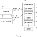
- the vibration monitoring system according to the present embodiment 1 includes a management device 10, a sensing device 20, and a vibration monitoring device 30.
- the management device 10 is a device for managing the shield machine, which is a source of vibration in tunnel construction carried out by construction companies. Specifically, the management device 10 manages the operating status of the shield machine, etc.
- the sensing device 20 is a device that performs optical fiber sensing using optical fibers laid around the area where the shield machine is operating at the construction site where tunnel construction is being carried out, and is realized, for example, by a DFOS (Distributed Fiber Optic Sensing) device. Specifically, the sensing device 20 performs optical fiber sensing to detect vibrations and the vibration intensity of the vibrations at each of multiple measurement points on the optical fiber. Note that the optical fiber used by the sensing device 20 for optical fiber sensing may be one or multiple.
- the vibration monitoring device 30 is a device for monitoring vibrations occurring around the area where the shield machine is operating at a construction site where tunnel construction is being carried out, and is equipped with a first acquisition unit 31, a second acquisition unit 32, and a processing unit 33.
- the first acquisition unit 31 is connected to the management device 10 via a wireless or wired line, and acquires from the management device 10 operation data indicating the operation status of the shield machine, which is the source of vibration in tunnel construction, in a chronological order.
- the second acquisition unit 32 is connected to the sensing device 20 via a wireless or wired line, and acquires from the sensing device 20 sensing data indicating time-series changes in vibration intensity of vibrations detected at each of multiple measurement points on the optical fiber by optical fiber sensing.
- the processing unit 33 correlates the shield machine operation data and the sensing data by performing time synchronization between the shield machine operation data acquired from the management device 10 by the first acquisition unit 31 and the sensing data acquired from the sensing device 20 by the second acquisition unit 32.
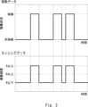
- FIG. 2 shows an example of the result of matching sensing data indicating the vibration intensity of vibrations detected at a certain measurement point with operation data of the shield machine, performed by the processing unit 33.
- the processing unit 33 classifies the vibration intensity in the sensing data into one of three levels: A or higher, B or higher (A>B), and B or lower, and then matches the sensing data with the operation data.
- the processing unit 33 may match the sensing data with the operation data without classifying the vibration intensity in the sensing data into one of the above levels, leaving it as a raw numerical value.
- the first acquisition unit 31, the second acquisition unit 32, and the processing unit 33 are provided in the same vibration monitoring device 30, but this is not limited to the above and they may be arranged separately from each other.
- the first acquisition unit 31, the second acquisition unit 32, and the processing unit 33 may be arranged in separate devices.
- the first acquisition unit 31, the second acquisition unit 32, and the processing unit 33 may be arranged on the cloud.
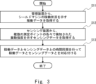
- the first acquisition unit 31 acquires operation data indicating the operation status of the shield machine in chronological order from the management device 10 that manages the shield machine, which is a vibration generating source in tunnel construction (step S11).
- the second acquisition unit 32 also acquires sensing data indicating time-series changes in vibration intensity of vibrations detected by optical fiber sensing at each of multiple measurement points on the optical fiber from the sensing device 20 that performs optical fiber sensing using optical fiber laid around the area where the shield machine is operating at the construction site where tunnel construction is being carried out (step S12).
- steps S11 and S12 may be reversed, with step S11 being performed after step S12. Alternatively, steps S11 and S12 may be performed in parallel, approximately simultaneously.
- the processing unit 33 time-synchronizes the shield machine operation data acquired from the management device 10 by the first acquisition unit 31 with the sensing data acquired from the sensing device 20 by the second acquisition unit 32, thereby associating the shield machine operation data with the sensing data (step S13).
- the first acquisition unit 31 acquires operation data indicating the operation status of the shield machine in a time series from the management device 10 that manages the shield machine, which is a vibration generating source in tunnel construction.
- the second acquisition unit 32 acquires sensing data indicating the time series change in vibration intensity of vibration detected at each of multiple measurement points on the optical fiber by optical fiber sensing from the sensing device 20 that performs optical fiber sensing using optical fiber laid around the area where the shield machine is operated at the construction site where tunnel construction is being carried out.
- the processing unit 33 associates the shield machine operation data with the sensing data by performing time synchronization between the shield machine operation data acquired from the management device 10 and the sensing data acquired from the sensing device 20.
- the vibration monitoring system according to the second embodiment differs from the configuration of the first embodiment shown in Fig. 1 in that a display unit 40 is added and a display control unit 34 is added inside the vibration monitoring device 30.
- the display unit 40 is realized by a display, monitor, etc. Note that in FIG. 4, the display unit 40 is provided outside the vibration monitoring device 30, but this is not limited thereto, and the display unit 40 may be provided inside the vibration monitoring device 30.
- the display control unit 34 causes various GUI (Graphical User Interface) screens to be displayed on the display unit 40.
- GUI Graphic User Interface
- the display control unit 34 causes each of the multiple measurement points to be displayed on the display unit 40 together with the vibration intensity detected at that measurement point, superimposed on a map.
- the display control unit 34 also causes the display unit 40 to display the shield machine, which is the source of vibration, together with the operating status of the shield machine, superimposed on a map.
- the positions of each of the multiple measurement points and the position of the optical fiber may be known, or may be acquired from the sensing device 20, for example, at the same time that sensing data is acquired.
- the position of the shield machine may be known, or may be acquired from the management device 10, for example, at the same time that operation data is acquired.
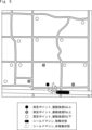
- FIG. 5 shows an example of a GUI screen that the display control unit 34 causes the display unit 40 to display.
- each of the multiple measurement points is displayed superimposed on the map in a manner corresponding to the level of vibration intensity detected at that measurement point (similar to FIG. 2, three levels: A or more, B or more (A>B), and B or less).
- each measurement point is displayed with hatching corresponding to the level of vibration intensity.
- the method of displaying vibration intensity at each measurement point in FIG. 5 is one example and is not limited to this.
- the color or shape of the mark for each measurement point may be changed according to the level of vibration intensity.
- the numerical value or level of vibration intensity may be displayed in text near each measurement point.
- the shield machine is displayed superimposed on the map in a manner that corresponds to the operation status of the shield machine. Specifically, the shield machine is displayed with hatching that corresponds to the operation status.
- the method of displaying the operation status of the shield machine in Figure 5 is one example and is not limited to this.
- the color of the shield machine may be changed depending on the operation status, or the shape of the mark may be changed.
- the operation status may be displayed in text near the shield machine.
- steps S21 to S23 are performed, which are similar to steps S11 to S13 in FIG. 3 of the above-mentioned first embodiment.
- the display control unit 34 causes the display unit 40 to display each of the multiple measurement points together with the vibration intensity detected at that measurement point, superimposed on the map.
- the display control unit 34 also causes the display unit 40 to display the shield machine, which is the source of the vibration, together with the operating status of the shield machine, superimposed on the map (step S24).
- the display control unit 34 causes the display unit 40 to display each of the multiple measurement points together with the vibration intensity detected at that measurement point, superimposed on the map.
- the display control unit 34 also causes the display unit 40 to display the shield machine, which is the vibration source, together with the operating status of the shield machine, superimposed on the map. This allows the positions of the multiple measurement points and the vibration intensity of the vibration detected at those measurement points to be visually recognized. Also, the position of the shield machine and the operating status of the shield machine can be visually recognized. The other effects are the same as those of the first embodiment described above.
- the processing unit 33 associated the operation data of the shield machine obtained from the management device 10 with the sensing data obtained from the sensing device 20, but further additional processing may be performed thereafter.
- the processing unit 33 may determine the causal relationship between the vibrations detected at each of the multiple measurement points and the operating status of the shield machine based on the results of matching the shield machine's operating data with the sensing data.
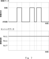
- the processing unit 33 the result of associating sensing data indicating the vibration intensity of vibrations detected at a certain measurement point with the operation data of the shield machine is shown in FIG. 2, and the result of associating sensing data indicating the vibration intensity of vibrations detected at a measurement point other than that of FIG. 2 with the operation data of the shield machine is shown in FIG. 7.
- the processing unit 33 determines that vibrations are occurring at the measurement point in Figure 2 due to the influence of the operating status of the shield machine.
- the processing unit 33 determines that vibration is occurring at the measurement point in Figure 7 without being affected by the operating status of the shield machine.
- the processing unit 33 may identify, among the multiple measurement points, a measurement point that is not affected by the operating status of the shield machine and where a vibration intensity equal to or greater than a threshold value is detected, based on the results of the causal relationship determination described above.
- the processing unit 33 may determine that an abnormality has occurred or that there are signs of an abnormality occurring at the measurement points identified as described above. For example, if "A" in FIG. 7 is the threshold value, the processing unit 33 identifies the measurement points in FIG. 7 as measurement points that are not affected by the operating status of the shield machine and where vibration intensity equal to or greater than the threshold value has been detected, and determines that an abnormality has occurred or that there are signs of an abnormality occurring at the measurement points in FIG. 7.
- the processing unit 33 may also control the shield machine based on the results of the causal relationship determination described above. For example, the processing unit 33 may control the strength of the vibrations generated by the shield machine, the intervals between vibration occurrences, etc. This allows the results of the causal relationship determination described above to be fed back to the construction work.
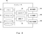
- the computer 90 includes a processor 91, a memory 92, a storage 93, an input/output interface (input/output I/F) 94, and a communication interface (communication I/F) 95.
- the processor 91, the memory 92, the storage 93, the input/output interface 94, and the communication interface 95 are connected by a data transmission path for transmitting and receiving data to and from each other.
- the processor 91 is, for example, an arithmetic processing device such as a CPU (Central Processing Unit) or a GPU (Graphics Processing Unit).
- the memory 92 is, for example, a memory such as a RAM (Random Access Memory) or a ROM (Read Only Memory).
- the storage 93 is, for example, a storage device such as a HDD (Hard Disk Drive), an SSD (Solid State Drive), or a memory card.
- the storage 93 may also be a memory such as a RAM or ROM.
- Storage 93 stores programs that realize the functions of the components of vibration monitoring device 30.
- Processor 91 executes each of these programs to realize the functions of each of the components of vibration monitoring device 30.
- processor 91 may read these programs onto memory 92 before executing them, or may execute them without reading them onto memory 92.
- Memory 92 and storage 93 also serve to store information and data held by the components of vibration monitoring device 30.
- Non-transitory computer readable medium includes various types of tangible storage medium.
- Examples of non-transitory computer readable medium include magnetic recording media (e.g., flexible disks, magnetic tapes, hard disk drives), magneto-optical recording media (e.g., magneto-optical disks), Compact Disc-ROM (CD-ROM), CD-Recordable (CD-R), CD-ReWritable (CD-R/W), and semiconductor memory (e.g., mask ROM, Programmable ROM (PROM), Erasable PROM (EPROM), flash ROM, RAM).
- magnetic recording media e.g., flexible disks, magnetic tapes, hard disk drives
- magneto-optical recording media e.g., magneto-optical disks
- CD-ROM Compact Disc-ROM
- CD-R CD-Recordable
- CD-R/W CD-ReWritable
- semiconductor memory e.g., mask ROM, Programmable ROM (PROM), Erasable PROM (EPROM), flash ROM,
- the program may also be supplied to a computer by various types of transitory computer readable medium.
- Examples of transitory computer readable medium include electrical signals, optical signals, and electromagnetic waves.
- the temporary computer-readable medium can provide the program to the computer via a wired communication path, such as an electric wire or optical fiber, or via a wireless communication path.
- the input/output interface 94 is connected to a display device 941, an input device 942, a sound output device 943, etc.
- the display device 941 is a device that displays a screen corresponding to drawing data processed by the processor 91, such as an LCD (Liquid Crystal Display), a CRT (Cathode Ray Tube) display, or a monitor.
- the input device 942 is a device that accepts operational input from an operator, such as a keyboard, a mouse, or a touch sensor.
- the display device 941 and the input device 942 may be integrated and realized as a touch panel.
- the sound output device 943 is a device that acoustically outputs sound corresponding to the audio data processed by the processor 91, such as a speaker.
- the communication interface 95 transmits and receives data to and from an external device.
- the communication interface 95 communicates with the external device via a wired communication path or a wireless communication path.
- a management device for managing a vibration source a sensing device that performs optical fiber sensing using optical fibers laid around an area in which the vibration generating source is operated; a first acquisition unit that acquires operation data indicating an operation status of the vibration generation source in a time series from the management device; a second acquisition unit that acquires sensing data indicating a time series change in vibration intensity of vibration detected at each of a plurality of measurement points on the optical fiber by the optical fiber sensing from the sensing device; a processing unit that associates the operation data with the sensing data by performing time synchronization between the operation data and the sensing data, Vibration monitoring system.
- the processing unit determines a causal relationship between the vibration detected at each of the plurality of measurement points and an operating status of the vibration generation source based on a result of the association. 2.
- the vibration monitoring system of claim 1. (Appendix 3) The processing unit, based on a result of the determination of the causal relationship, identifies a measurement point among the plurality of measurement points that is not affected by the operating status of the vibration generation source and at which a vibration intensity equal to or greater than a threshold value is detected, and determines that an abnormality has occurred or there is a sign of an abnormality occurring at the identified measurement point. 3.
- (Appendix 4) a display control unit that causes each of the plurality of measurement points to be superimposed on a map together with vibration intensities detected at the measurement points to be displayed on a display unit, and causes the vibration generation source to be superimposed on the map together with an operation status of the vibration generation source to be displayed on the display unit.
- the vibration monitoring system of claim 1. the display control unit causes each of the plurality of measurement points to be superimposed on the map in a manner corresponding to a level of vibration intensity detected at the measurement point, and causes the display unit to display the vibration generation source in a manner corresponding to an operation status of the vibration generation source in a manner superimposed on the map. 5.
- the processing unit controls the vibration generation source based on a result of the determination of the causal relationship.
- the vibration monitoring system of claim 2. (Appendix 7) a first acquisition unit that acquires operation data indicating an operation status of the vibration generation source in a time series from a management device that manages the vibration generation source; a second acquisition unit that acquires, from a sensing device that performs optical fiber sensing using an optical fiber laid around an area in which the vibration generating source is operated, sensing data that indicates a time series change in vibration intensity of vibration detected at each of a plurality of measurement points on the optical fiber by the optical fiber sensing; a processing unit that associates the operation data with the sensing data by performing time synchronization between the operation data and the sensing data, Vibration monitoring device.
- the processing unit determines a causal relationship between the vibration detected at each of the plurality of measurement points and an operating status of the vibration generation source based on a result of the association.
- the vibration monitoring device of claim 7. (Appendix 9) The processing unit, based on a result of the determination of the causal relationship, identifies a measurement point among the plurality of measurement points that is not affected by the operating status of the vibration generation source and at which a vibration intensity equal to or greater than a threshold value is detected, and determines that an abnormality has occurred or there is a sign of an abnormality occurring at the identified measurement point. 9.
- (Appendix 10) a display control unit that causes each of the plurality of measurement points to be superimposed on a map together with vibration intensities detected at the measurement points to be displayed on a display unit, and causes the vibration generation source to be superimposed on the map together with an operation status of the vibration generation source to be displayed on the display unit.
- the display control unit causes each of the plurality of measurement points to be superimposed on the map in a manner corresponding to a level of vibration intensity detected at the measurement point, and causes the display unit to display the vibration generation source in a manner corresponding to an operation status of the vibration generation source in a manner superimposed on the map.
- a vibration monitoring method using a vibration monitoring device comprising: a first acquisition step of acquiring operation data indicating an operation status of the vibration generation source in a time series from a management device that manages the vibration generation source; a second acquisition step of acquiring, from a sensing device that performs optical fiber sensing using an optical fiber laid around an area in which the vibration generating source is operated, sensing data indicating a time series change in vibration intensity of vibration detected at each of a plurality of measurement points on the optical fiber by the optical fiber sensing; A processing step of associating the operation data with the sensing data by performing time synchronization between the operation data and the sensing data.
- Vibration monitoring methods In the processing step, a causal relationship between the vibration detected at each of the plurality of measurement points and an operating state of the vibration generation source is determined based on a result of the pre-association. 14. The vibration monitoring method of claim 13. (Appendix 15) In the processing step, based on the result of the determination of the causal relationship, a measurement point that is not affected by the operating status of the vibration generation source and at which a vibration intensity equal to or greater than a threshold is detected is identified from among the plurality of measurement points, and it is determined that an abnormality has occurred or there is a sign of an abnormality occurring at the identified measurement point. 15. The vibration monitoring method of claim 14.
- a device for managing vibrations caused by construction work For example, an operation management device for managing the operation of heavy construction machinery.
- - Devices that manage vibrations caused by train movements such as traffic management devices that manage train operations.
- - Devices that control vibrations caused by factory machinery For example, operation control devices that control factory operations.
- a device for managing vibrations caused by vehicles such as a vehicle traffic management device for managing the traffic of vehicles on a road.
Landscapes
- Physics & Mathematics (AREA)
- General Physics & Mathematics (AREA)
- Measurement Of Mechanical Vibrations Or Ultrasonic Waves (AREA)
Abstract
Système de surveillance de vibrations, selon la présente divulgation, comprenant : un dispositif de gestion (10) qui gère une source de génération de vibrations ; un dispositif de détection (20) qui exécute une détection de fibre optique à l'aide d'une fibre optique disposée autour d'une zone dans laquelle la source de génération de vibration est actionnée ; une première unité d'acquisition (31) qui acquiert, à partir du dispositif de gestion (10), des données de fonctionnement indiquant, en série chronologique, l'état de fonctionnement de la source de génération de vibrations ; une seconde unité d'acquisition (32) qui acquiert, à partir du dispositif de détection (20), des données de détection indiquant un changement de série chronologique de l'intensité de vibration de vibrations détectées au niveau de chacun d'une pluralité de points de mesure sur la fibre optique au moyen de la détection de fibre optique ; et une unité de traitement (33) qui associe les données de fonctionnement et les données de détection en effectuant une synchronisation temporelle entre les données de fonctionnement et les données de détection.
Priority Applications (2)
| Application Number | Priority Date | Filing Date | Title |
|---|---|---|---|
| JP2025525452A JPWO2024252476A1 (fr) | 2023-06-05 | 2023-06-05 | |
| PCT/JP2023/020829 WO2024252476A1 (fr) | 2023-06-05 | 2023-06-05 | Système de surveillance de vibrations, dispositif de surveillance de vibrations et procédé de surveillance de vibrations |
Applications Claiming Priority (1)
| Application Number | Priority Date | Filing Date | Title |
|---|---|---|---|
| PCT/JP2023/020829 WO2024252476A1 (fr) | 2023-06-05 | 2023-06-05 | Système de surveillance de vibrations, dispositif de surveillance de vibrations et procédé de surveillance de vibrations |
Publications (1)
| Publication Number | Publication Date |
|---|---|
| WO2024252476A1 true WO2024252476A1 (fr) | 2024-12-12 |
Family
ID=93795135
Family Applications (1)
| Application Number | Title | Priority Date | Filing Date |
|---|---|---|---|
| PCT/JP2023/020829 Ceased WO2024252476A1 (fr) | 2023-06-05 | 2023-06-05 | Système de surveillance de vibrations, dispositif de surveillance de vibrations et procédé de surveillance de vibrations |
Country Status (2)
| Country | Link |
|---|---|
| JP (1) | JPWO2024252476A1 (fr) |
| WO (1) | WO2024252476A1 (fr) |
Citations (2)
| Publication number | Priority date | Publication date | Assignee | Title |
|---|---|---|---|---|
| WO2021010251A1 (fr) * | 2019-07-17 | 2021-01-21 | 日本電気株式会社 | Système de détection à fibres optiques, équipement de détection à fibres optiques et procédé d'évaluation d'anomalie |
| WO2022034748A1 (fr) * | 2020-08-13 | 2022-02-17 | 日本電気株式会社 | Dispositif de surveillance de bruit subaquatique, procédé de surveillance de bruit subaquatique et support de stockage |
-
2023
- 2023-06-05 WO PCT/JP2023/020829 patent/WO2024252476A1/fr not_active Ceased
- 2023-06-05 JP JP2025525452A patent/JPWO2024252476A1/ja active Pending
Patent Citations (2)
| Publication number | Priority date | Publication date | Assignee | Title |
|---|---|---|---|---|
| WO2021010251A1 (fr) * | 2019-07-17 | 2021-01-21 | 日本電気株式会社 | Système de détection à fibres optiques, équipement de détection à fibres optiques et procédé d'évaluation d'anomalie |
| WO2022034748A1 (fr) * | 2020-08-13 | 2022-02-17 | 日本電気株式会社 | Dispositif de surveillance de bruit subaquatique, procédé de surveillance de bruit subaquatique et support de stockage |
Also Published As
| Publication number | Publication date |
|---|---|
| JPWO2024252476A1 (fr) | 2024-12-12 |
Similar Documents
| Publication | Publication Date | Title |
|---|---|---|
| US20240271969A1 (en) | Utility pole deterioration detection system, utility pole deterioration detection apparatus, utility pole deterioration detection method, and non-transitory computer readable medium | |
| WO2020116030A1 (fr) | Système de surveillance de route, dispositif de surveillance de route, procédé de surveillance de route et support lisible par ordinateur non temporaire | |
| US12154007B2 (en) | Fiber sensing on roadside applications | |
| JP2024014948A (ja) | 道路監視システム、道路監視装置、道路監視方法、及びプログラム | |
| JP7235115B2 (ja) | 光ファイバセンシングシステム、光ファイバセンシング機器、及び異常判断方法 | |
| WO2024004119A1 (fr) | Système de détection, dispositif de détection et procédé de détection | |
| CN118774973A (zh) | 大煤柱掘进的监控方法及装置 | |
| JP7533566B2 (ja) | 監視システム、監視装置、及び監視方法 | |
| US20220277641A1 (en) | Optical fiber sensing system, optical fiber sensing equipment, and rescue request detection method | |
| WO2024252476A1 (fr) | Système de surveillance de vibrations, dispositif de surveillance de vibrations et procédé de surveillance de vibrations | |
| US20220326070A1 (en) | Fiber optic sensing for reduced field work conflicts | |
| WO2022113252A1 (fr) | Système de spécification de position, générateur de vibrations et procédé de spécification de position | |
| US20210372828A1 (en) | Civil engineering structure monitoring system, civil engineering structure monitoring apparatus, civil engineering structure monitoring method, and non-transitory computer-readable medium | |
| WO2020116031A1 (fr) | Système de surveillance de voie ferrée dispositif de surveillance de voie ferrée, procédé de surveillance de voie ferrée et support non transitoire lisible par ordinateur | |
| JP7416233B2 (ja) | 異常検出システム、異常検出装置、異常検出方法、及びプログラム | |
| US20240361178A1 (en) | Monitoring system, monitoring apparatus, and monitoring method | |
| JP2021034917A (ja) | センサ設置支援装置、センサ設置支援方法およびプログラム | |
| CN110095182A (zh) | 隧道噪声检测装置及方法 | |
| US20230070029A1 (en) | Detection system, detection device, and detection method | |
| US20230417593A1 (en) | Optical fiber sensing system, optical fiber sensing method, and optical fiber sensing device | |
| US20230128841A1 (en) | Damaged part identifying apparatus, method and program | |
| US20230081172A1 (en) | Power failure detection system, power failure detection device, and power failure detection method | |
| JP7525082B1 (ja) | 設備監視システム、及び設備監視方法 | |
| CN118585744B (zh) | 一种数据处理方法、装置、机械设备和存储介质 | |
| JP2021033731A (ja) | 被災把握システム、処理装置及びプログラム |
Legal Events
| Date | Code | Title | Description |
|---|---|---|---|
| 121 | Ep: the epo has been informed by wipo that ep was designated in this application |
Ref document number: 23940583 Country of ref document: EP Kind code of ref document: A1 |
|
| ENP | Entry into the national phase |
Ref document number: 2025525452 Country of ref document: JP Kind code of ref document: A |
|
| NENP | Non-entry into the national phase |
Ref country code: DE |