WO2024252476A1 - 振動監視システム、振動監視装置、及び振動監視方法 - Google Patents
振動監視システム、振動監視装置、及び振動監視方法 Download PDFInfo
- Publication number
- WO2024252476A1 WO2024252476A1 PCT/JP2023/020829 JP2023020829W WO2024252476A1 WO 2024252476 A1 WO2024252476 A1 WO 2024252476A1 JP 2023020829 W JP2023020829 W JP 2023020829W WO 2024252476 A1 WO2024252476 A1 WO 2024252476A1
- Authority
- WO
- WIPO (PCT)
- Prior art keywords
- vibration
- generation source
- sensing
- measurement points
- optical fiber
- Prior art date
- Legal status (The legal status is an assumption and is not a legal conclusion. Google has not performed a legal analysis and makes no representation as to the accuracy of the status listed.)
- Ceased
Links
Images


Classifications
-
- G—PHYSICS
- G01—MEASURING; TESTING
- G01H—MEASUREMENT OF MECHANICAL VIBRATIONS OR ULTRASONIC, SONIC OR INFRASONIC WAVES
- G01H9/00—Measuring mechanical vibrations or ultrasonic, sonic or infrasonic waves by using radiation-sensitive means, e.g. optical means
Definitions
- This disclosure relates to a vibration monitoring system, a vibration monitoring device, and a vibration monitoring method.
- Patent Document 1 describes a technology for monitoring vibrations caused by road construction. Specifically, the technology described in Patent Document 1 observes the interference of light transmitted through an optical fiber embedded in or installed alongside a power cable. When road construction is carried out near a power cable, vibrations are generated and distortion occurs in the optical fiber. Therefore, the presence or absence of road construction can be detected by observing the interference of light.
- Patent Document 1 is capable of detecting whether road construction is taking place.
- the sources of vibration generated during road construction e.g., bulldozers
- the sources of vibration generated during road construction are not always in operation, and there are times when they are not in operation.
- Patent Document 1 cannot grasp the operating status of a vibration generating source when vibration occurs around a construction site. Therefore, simply using the technology described in Patent Document 1 does not allow efficient construction work to be carried out while minimizing the impact of vibration on surrounding residents. Therefore, there is a demand for technology that can grasp the operating status of a vibration generating source when vibration occurs around an area where the vibration generating source is operating at a construction site or the like.
- the objective of this disclosure is to provide a vibration monitoring system, a vibration monitoring device, and a vibration monitoring method that can grasp the operating status of a vibration generating source when vibration occurs in the vicinity of the area in which the vibration generating source is operated.
- a vibration monitoring system includes: A management device for managing a vibration source; a sensing device that performs optical fiber sensing using optical fibers laid around an area in which the vibration generating source is operated; a first acquisition unit that acquires operation data indicating an operation status of the vibration generation source in a time series from the management device; a second acquisition unit that acquires sensing data indicating a time series change in vibration intensity of vibration detected at each of a plurality of measurement points on the optical fiber by the optical fiber sensing from the sensing device; The system further includes a processing unit that associates the operation data with the sensing data by performing time synchronization between the operation data and the sensing data.
- a vibration monitoring device includes: a first acquisition unit that acquires operation data indicating an operation status of the vibration generation source in a time series from a management device that manages the vibration generation source; a second acquisition unit that acquires, from a sensing device that performs optical fiber sensing using an optical fiber laid around an area in which the vibration generating source is operated, sensing data that indicates a time series change in vibration intensity of vibration detected at each of a plurality of measurement points on the optical fiber by the optical fiber sensing; The system further includes a processing unit that associates the operation data with the sensing data by performing time synchronization between the operation data and the sensing data.
- a vibration monitoring method includes the steps of: A vibration monitoring method using a vibration monitoring device, comprising: a first acquisition step of acquiring operation data indicating an operation status of the vibration generation source in a time series from a management device that manages the vibration generation source; a second acquisition step of acquiring, from a sensing device that performs optical fiber sensing using an optical fiber laid around an area in which the vibration generating source is operated, sensing data indicating a time series change in vibration intensity of vibration detected at each of a plurality of measurement points on the optical fiber by the optical fiber sensing;
- the method includes a processing step of associating the operation data with the sensing data by performing time synchronization between the operation data and the sensing data.
- the above-mentioned aspects have the advantage of providing a vibration monitoring system, a vibration monitoring device, and a vibration monitoring method that can grasp the operating status of a vibration generating source when vibration occurs in the vicinity of an area in which the vibration generating source is operated.
- FIG. 1 is a diagram illustrating a configuration example of a vibration monitoring system according to a first embodiment
- 4 is a flowchart showing an example of a schematic operation flow of the vibration monitoring device according to the first embodiment.
- FIG. 11 is a diagram illustrating a configuration example of a vibration monitoring system according to a second embodiment.
- 13 is a diagram showing an example of a GUI screen that a display control unit according to the second embodiment causes to be displayed on a display unit;
- FIG. 11 is a flowchart showing an example of a schematic operation flow of a vibration monitoring device according to a second embodiment.
- FIG. 1 A figure showing another example of the result of matching sensing data indicating the vibration intensity of vibration detected at a certain measurement point with operation data of a shield machine in a processing unit related to embodiments 1 and 2.
- 2 is a block diagram showing an example of a hardware configuration of a computer that realizes the vibration monitoring device according to the first and second embodiments.
- the vibration source will be described as a vibration source in construction work.
- the vibration source is not limited to a vibration source in construction work, and may be, for example, a vibration source in a factory.
- the type of construction work will be described as tunnel construction, for example, tunnel construction using a blasting method, and the type of vibration source in construction work will be described as a shield machine.
- the type of construction work is not limited to tunnel construction, and may be, for example, other civil engineering work such as road construction, or construction work for buildings such as buildings.
- the type of vibration source is not limited to a shield machine, and may be, for example, other construction vehicles such as bulldozers, power shovels, and dump trucks.
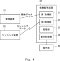
- the vibration monitoring system according to the present embodiment 1 includes a management device 10, a sensing device 20, and a vibration monitoring device 30.
- the management device 10 is a device for managing the shield machine, which is a source of vibration in tunnel construction carried out by construction companies. Specifically, the management device 10 manages the operating status of the shield machine, etc.
- the sensing device 20 is a device that performs optical fiber sensing using optical fibers laid around the area where the shield machine is operating at the construction site where tunnel construction is being carried out, and is realized, for example, by a DFOS (Distributed Fiber Optic Sensing) device. Specifically, the sensing device 20 performs optical fiber sensing to detect vibrations and the vibration intensity of the vibrations at each of multiple measurement points on the optical fiber. Note that the optical fiber used by the sensing device 20 for optical fiber sensing may be one or multiple.
- the vibration monitoring device 30 is a device for monitoring vibrations occurring around the area where the shield machine is operating at a construction site where tunnel construction is being carried out, and is equipped with a first acquisition unit 31, a second acquisition unit 32, and a processing unit 33.
- the first acquisition unit 31 is connected to the management device 10 via a wireless or wired line, and acquires from the management device 10 operation data indicating the operation status of the shield machine, which is the source of vibration in tunnel construction, in a chronological order.
- the second acquisition unit 32 is connected to the sensing device 20 via a wireless or wired line, and acquires from the sensing device 20 sensing data indicating time-series changes in vibration intensity of vibrations detected at each of multiple measurement points on the optical fiber by optical fiber sensing.
- the processing unit 33 correlates the shield machine operation data and the sensing data by performing time synchronization between the shield machine operation data acquired from the management device 10 by the first acquisition unit 31 and the sensing data acquired from the sensing device 20 by the second acquisition unit 32.
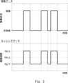
- FIG. 2 shows an example of the result of matching sensing data indicating the vibration intensity of vibrations detected at a certain measurement point with operation data of the shield machine, performed by the processing unit 33.
- the processing unit 33 classifies the vibration intensity in the sensing data into one of three levels: A or higher, B or higher (A>B), and B or lower, and then matches the sensing data with the operation data.
- the processing unit 33 may match the sensing data with the operation data without classifying the vibration intensity in the sensing data into one of the above levels, leaving it as a raw numerical value.
- the first acquisition unit 31, the second acquisition unit 32, and the processing unit 33 are provided in the same vibration monitoring device 30, but this is not limited to the above and they may be arranged separately from each other.
- the first acquisition unit 31, the second acquisition unit 32, and the processing unit 33 may be arranged in separate devices.
- the first acquisition unit 31, the second acquisition unit 32, and the processing unit 33 may be arranged on the cloud.
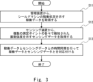
- the first acquisition unit 31 acquires operation data indicating the operation status of the shield machine in chronological order from the management device 10 that manages the shield machine, which is a vibration generating source in tunnel construction (step S11).
- the second acquisition unit 32 also acquires sensing data indicating time-series changes in vibration intensity of vibrations detected by optical fiber sensing at each of multiple measurement points on the optical fiber from the sensing device 20 that performs optical fiber sensing using optical fiber laid around the area where the shield machine is operating at the construction site where tunnel construction is being carried out (step S12).
- steps S11 and S12 may be reversed, with step S11 being performed after step S12. Alternatively, steps S11 and S12 may be performed in parallel, approximately simultaneously.
- the processing unit 33 time-synchronizes the shield machine operation data acquired from the management device 10 by the first acquisition unit 31 with the sensing data acquired from the sensing device 20 by the second acquisition unit 32, thereby associating the shield machine operation data with the sensing data (step S13).
- the first acquisition unit 31 acquires operation data indicating the operation status of the shield machine in a time series from the management device 10 that manages the shield machine, which is a vibration generating source in tunnel construction.
- the second acquisition unit 32 acquires sensing data indicating the time series change in vibration intensity of vibration detected at each of multiple measurement points on the optical fiber by optical fiber sensing from the sensing device 20 that performs optical fiber sensing using optical fiber laid around the area where the shield machine is operated at the construction site where tunnel construction is being carried out.
- the processing unit 33 associates the shield machine operation data with the sensing data by performing time synchronization between the shield machine operation data acquired from the management device 10 and the sensing data acquired from the sensing device 20.
- the vibration monitoring system according to the second embodiment differs from the configuration of the first embodiment shown in Fig. 1 in that a display unit 40 is added and a display control unit 34 is added inside the vibration monitoring device 30.
- the display unit 40 is realized by a display, monitor, etc. Note that in FIG. 4, the display unit 40 is provided outside the vibration monitoring device 30, but this is not limited thereto, and the display unit 40 may be provided inside the vibration monitoring device 30.
- the display control unit 34 causes various GUI (Graphical User Interface) screens to be displayed on the display unit 40.
- GUI Graphic User Interface
- the display control unit 34 causes each of the multiple measurement points to be displayed on the display unit 40 together with the vibration intensity detected at that measurement point, superimposed on a map.
- the display control unit 34 also causes the display unit 40 to display the shield machine, which is the source of vibration, together with the operating status of the shield machine, superimposed on a map.
- the positions of each of the multiple measurement points and the position of the optical fiber may be known, or may be acquired from the sensing device 20, for example, at the same time that sensing data is acquired.
- the position of the shield machine may be known, or may be acquired from the management device 10, for example, at the same time that operation data is acquired.
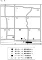
- FIG. 5 shows an example of a GUI screen that the display control unit 34 causes the display unit 40 to display.
- each of the multiple measurement points is displayed superimposed on the map in a manner corresponding to the level of vibration intensity detected at that measurement point (similar to FIG. 2, three levels: A or more, B or more (A>B), and B or less).
- each measurement point is displayed with hatching corresponding to the level of vibration intensity.
- the method of displaying vibration intensity at each measurement point in FIG. 5 is one example and is not limited to this.
- the color or shape of the mark for each measurement point may be changed according to the level of vibration intensity.
- the numerical value or level of vibration intensity may be displayed in text near each measurement point.
- the shield machine is displayed superimposed on the map in a manner that corresponds to the operation status of the shield machine. Specifically, the shield machine is displayed with hatching that corresponds to the operation status.
- the method of displaying the operation status of the shield machine in Figure 5 is one example and is not limited to this.
- the color of the shield machine may be changed depending on the operation status, or the shape of the mark may be changed.
- the operation status may be displayed in text near the shield machine.
- steps S21 to S23 are performed, which are similar to steps S11 to S13 in FIG. 3 of the above-mentioned first embodiment.
- the display control unit 34 causes the display unit 40 to display each of the multiple measurement points together with the vibration intensity detected at that measurement point, superimposed on the map.
- the display control unit 34 also causes the display unit 40 to display the shield machine, which is the source of the vibration, together with the operating status of the shield machine, superimposed on the map (step S24).
- the display control unit 34 causes the display unit 40 to display each of the multiple measurement points together with the vibration intensity detected at that measurement point, superimposed on the map.
- the display control unit 34 also causes the display unit 40 to display the shield machine, which is the vibration source, together with the operating status of the shield machine, superimposed on the map. This allows the positions of the multiple measurement points and the vibration intensity of the vibration detected at those measurement points to be visually recognized. Also, the position of the shield machine and the operating status of the shield machine can be visually recognized. The other effects are the same as those of the first embodiment described above.
- the processing unit 33 associated the operation data of the shield machine obtained from the management device 10 with the sensing data obtained from the sensing device 20, but further additional processing may be performed thereafter.
- the processing unit 33 may determine the causal relationship between the vibrations detected at each of the multiple measurement points and the operating status of the shield machine based on the results of matching the shield machine's operating data with the sensing data.
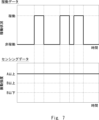
- the processing unit 33 the result of associating sensing data indicating the vibration intensity of vibrations detected at a certain measurement point with the operation data of the shield machine is shown in FIG. 2, and the result of associating sensing data indicating the vibration intensity of vibrations detected at a measurement point other than that of FIG. 2 with the operation data of the shield machine is shown in FIG. 7.
- the processing unit 33 determines that vibrations are occurring at the measurement point in Figure 2 due to the influence of the operating status of the shield machine.
- the processing unit 33 determines that vibration is occurring at the measurement point in Figure 7 without being affected by the operating status of the shield machine.
- the processing unit 33 may identify, among the multiple measurement points, a measurement point that is not affected by the operating status of the shield machine and where a vibration intensity equal to or greater than a threshold value is detected, based on the results of the causal relationship determination described above.
- the processing unit 33 may determine that an abnormality has occurred or that there are signs of an abnormality occurring at the measurement points identified as described above. For example, if "A" in FIG. 7 is the threshold value, the processing unit 33 identifies the measurement points in FIG. 7 as measurement points that are not affected by the operating status of the shield machine and where vibration intensity equal to or greater than the threshold value has been detected, and determines that an abnormality has occurred or that there are signs of an abnormality occurring at the measurement points in FIG. 7.
- the processing unit 33 may also control the shield machine based on the results of the causal relationship determination described above. For example, the processing unit 33 may control the strength of the vibrations generated by the shield machine, the intervals between vibration occurrences, etc. This allows the results of the causal relationship determination described above to be fed back to the construction work.
- the computer 90 includes a processor 91, a memory 92, a storage 93, an input/output interface (input/output I/F) 94, and a communication interface (communication I/F) 95.
- the processor 91, the memory 92, the storage 93, the input/output interface 94, and the communication interface 95 are connected by a data transmission path for transmitting and receiving data to and from each other.
- the processor 91 is, for example, an arithmetic processing device such as a CPU (Central Processing Unit) or a GPU (Graphics Processing Unit).
- the memory 92 is, for example, a memory such as a RAM (Random Access Memory) or a ROM (Read Only Memory).
- the storage 93 is, for example, a storage device such as a HDD (Hard Disk Drive), an SSD (Solid State Drive), or a memory card.
- the storage 93 may also be a memory such as a RAM or ROM.
- Storage 93 stores programs that realize the functions of the components of vibration monitoring device 30.
- Processor 91 executes each of these programs to realize the functions of each of the components of vibration monitoring device 30.
- processor 91 may read these programs onto memory 92 before executing them, or may execute them without reading them onto memory 92.
- Memory 92 and storage 93 also serve to store information and data held by the components of vibration monitoring device 30.
- Non-transitory computer readable medium includes various types of tangible storage medium.
- Examples of non-transitory computer readable medium include magnetic recording media (e.g., flexible disks, magnetic tapes, hard disk drives), magneto-optical recording media (e.g., magneto-optical disks), Compact Disc-ROM (CD-ROM), CD-Recordable (CD-R), CD-ReWritable (CD-R/W), and semiconductor memory (e.g., mask ROM, Programmable ROM (PROM), Erasable PROM (EPROM), flash ROM, RAM).
- magnetic recording media e.g., flexible disks, magnetic tapes, hard disk drives
- magneto-optical recording media e.g., magneto-optical disks
- CD-ROM Compact Disc-ROM
- CD-R CD-Recordable
- CD-R/W CD-ReWritable
- semiconductor memory e.g., mask ROM, Programmable ROM (PROM), Erasable PROM (EPROM), flash ROM,
- the program may also be supplied to a computer by various types of transitory computer readable medium.
- Examples of transitory computer readable medium include electrical signals, optical signals, and electromagnetic waves.
- the temporary computer-readable medium can provide the program to the computer via a wired communication path, such as an electric wire or optical fiber, or via a wireless communication path.
- the input/output interface 94 is connected to a display device 941, an input device 942, a sound output device 943, etc.
- the display device 941 is a device that displays a screen corresponding to drawing data processed by the processor 91, such as an LCD (Liquid Crystal Display), a CRT (Cathode Ray Tube) display, or a monitor.
- the input device 942 is a device that accepts operational input from an operator, such as a keyboard, a mouse, or a touch sensor.
- the display device 941 and the input device 942 may be integrated and realized as a touch panel.
- the sound output device 943 is a device that acoustically outputs sound corresponding to the audio data processed by the processor 91, such as a speaker.
- the communication interface 95 transmits and receives data to and from an external device.
- the communication interface 95 communicates with the external device via a wired communication path or a wireless communication path.
- a management device for managing a vibration source a sensing device that performs optical fiber sensing using optical fibers laid around an area in which the vibration generating source is operated; a first acquisition unit that acquires operation data indicating an operation status of the vibration generation source in a time series from the management device; a second acquisition unit that acquires sensing data indicating a time series change in vibration intensity of vibration detected at each of a plurality of measurement points on the optical fiber by the optical fiber sensing from the sensing device; a processing unit that associates the operation data with the sensing data by performing time synchronization between the operation data and the sensing data, Vibration monitoring system.
- the processing unit determines a causal relationship between the vibration detected at each of the plurality of measurement points and an operating status of the vibration generation source based on a result of the association. 2.
- the vibration monitoring system of claim 1. (Appendix 3) The processing unit, based on a result of the determination of the causal relationship, identifies a measurement point among the plurality of measurement points that is not affected by the operating status of the vibration generation source and at which a vibration intensity equal to or greater than a threshold value is detected, and determines that an abnormality has occurred or there is a sign of an abnormality occurring at the identified measurement point. 3.
- (Appendix 4) a display control unit that causes each of the plurality of measurement points to be superimposed on a map together with vibration intensities detected at the measurement points to be displayed on a display unit, and causes the vibration generation source to be superimposed on the map together with an operation status of the vibration generation source to be displayed on the display unit.
- the vibration monitoring system of claim 1. the display control unit causes each of the plurality of measurement points to be superimposed on the map in a manner corresponding to a level of vibration intensity detected at the measurement point, and causes the display unit to display the vibration generation source in a manner corresponding to an operation status of the vibration generation source in a manner superimposed on the map. 5.
- the processing unit controls the vibration generation source based on a result of the determination of the causal relationship.
- the vibration monitoring system of claim 2. (Appendix 7) a first acquisition unit that acquires operation data indicating an operation status of the vibration generation source in a time series from a management device that manages the vibration generation source; a second acquisition unit that acquires, from a sensing device that performs optical fiber sensing using an optical fiber laid around an area in which the vibration generating source is operated, sensing data that indicates a time series change in vibration intensity of vibration detected at each of a plurality of measurement points on the optical fiber by the optical fiber sensing; a processing unit that associates the operation data with the sensing data by performing time synchronization between the operation data and the sensing data, Vibration monitoring device.
- the processing unit determines a causal relationship between the vibration detected at each of the plurality of measurement points and an operating status of the vibration generation source based on a result of the association.
- the vibration monitoring device of claim 7. (Appendix 9) The processing unit, based on a result of the determination of the causal relationship, identifies a measurement point among the plurality of measurement points that is not affected by the operating status of the vibration generation source and at which a vibration intensity equal to or greater than a threshold value is detected, and determines that an abnormality has occurred or there is a sign of an abnormality occurring at the identified measurement point. 9.
- (Appendix 10) a display control unit that causes each of the plurality of measurement points to be superimposed on a map together with vibration intensities detected at the measurement points to be displayed on a display unit, and causes the vibration generation source to be superimposed on the map together with an operation status of the vibration generation source to be displayed on the display unit.
- the display control unit causes each of the plurality of measurement points to be superimposed on the map in a manner corresponding to a level of vibration intensity detected at the measurement point, and causes the display unit to display the vibration generation source in a manner corresponding to an operation status of the vibration generation source in a manner superimposed on the map.
- a vibration monitoring method using a vibration monitoring device comprising: a first acquisition step of acquiring operation data indicating an operation status of the vibration generation source in a time series from a management device that manages the vibration generation source; a second acquisition step of acquiring, from a sensing device that performs optical fiber sensing using an optical fiber laid around an area in which the vibration generating source is operated, sensing data indicating a time series change in vibration intensity of vibration detected at each of a plurality of measurement points on the optical fiber by the optical fiber sensing; A processing step of associating the operation data with the sensing data by performing time synchronization between the operation data and the sensing data.
- Vibration monitoring methods In the processing step, a causal relationship between the vibration detected at each of the plurality of measurement points and an operating state of the vibration generation source is determined based on a result of the pre-association. 14. The vibration monitoring method of claim 13. (Appendix 15) In the processing step, based on the result of the determination of the causal relationship, a measurement point that is not affected by the operating status of the vibration generation source and at which a vibration intensity equal to or greater than a threshold is detected is identified from among the plurality of measurement points, and it is determined that an abnormality has occurred or there is a sign of an abnormality occurring at the identified measurement point. 15. The vibration monitoring method of claim 14.
- a device for managing vibrations caused by construction work For example, an operation management device for managing the operation of heavy construction machinery.
- - Devices that manage vibrations caused by train movements such as traffic management devices that manage train operations.
- - Devices that control vibrations caused by factory machinery For example, operation control devices that control factory operations.
- a device for managing vibrations caused by vehicles such as a vehicle traffic management device for managing the traffic of vehicles on a road.
Landscapes
- Physics & Mathematics (AREA)
- General Physics & Mathematics (AREA)
- Measurement Of Mechanical Vibrations Or Ultrasonic Waves (AREA)
Abstract
本開示に係る振動監視システムは、振動発生源を管理する管理装置(10)と、振動発生源を動作させるエリアの周辺に敷設された光ファイバを用いて光ファイバセンシングを実行するセンシング装置(20)と、管理装置(10)から、振動発生源の稼働状況を時系列に示す稼働データを取得する第1取得部(31)と、センシング装置(20)から、光ファイバセンシングによって光ファイバ上の複数の測定ポイントの各々で検知された振動の振動強度の時系列変化を示すセンシングデータを取得する第2の取得部(32)と、稼働データとセンシングデータとの時間同期を行うことにより、稼働データとセンシングデータとを対応付ける処理部(33)と、を備える。
Description
本開示は、振動監視システム、振動監視装置、及び振動監視方法に関する。
トンネル工事、道路工事などの土木工事や、ビルなどの建物の建設工事では、大きな振動が発生する。例えば、シールド方式のトンネル工事では、シールドマシンで掘削を行うため、シールドマシンを振動発生源とする大きな振動が発生する。
そのため、工事現場の周辺住民が、工事で発生した振動によって、ストレスや不安を感じたり、体調が悪化したりするなどの影響を受けるといった社会問題が発生することもある。そのため、工事会社では、周辺住民から振動に関する苦情を受けることが多々ある。
周辺住民からの苦情が報告された場合の工事会社の対応としては、工事を一旦停止するという対応を取ることが一般的である。しかし、工事を停止すると、工事期間の長期化及び工事コストの増加といった事態が発生する。
このような状況を踏まえ、工事会社では、工事現場の周辺の振動を定期的に監視することによって、周辺住民への振動の影響を抑えた効率的な工事を進める必要がある。
しかし、人手によって工事現場周辺の振動を監視することとすると、監視のためのコスト及び時間が多大にかかってしまう。そのため、人手によらずに、工事で発生した振動を監視する技術の需要が高まっている。
しかし、人手によって工事現場周辺の振動を監視することとすると、監視のためのコスト及び時間が多大にかかってしまう。そのため、人手によらずに、工事で発生した振動を監視する技術の需要が高まっている。
例えば、特許文献1には、道路工事で発生した振動を監視する技術が記載されている。具体的には、特許文献1に記載の技術では、電力ケーブルに内蔵又は並設した光ファイバを伝送される光の干渉を観測する。電力ケーブルの周辺で道路工事が行われると、それに伴う振動が発生し、光ファイバに歪みが生じる。そのため、光の干渉を観測することにより、道路工事の有無を検知する。
上述したように、特許文献1に記載の技術は、道路工事の有無を検知することは可能である。ただし、道路工事における振動発生源(例えば、ブルドーザーなど)は、常時稼働している訳ではなく、非稼働の時間帯も存在する。
しかし、特許文献1に記載の技術は、工事現場の周辺で振動が発生したときの振動発生源の稼働状況を把握することができない。そのため、特許文献1に記載の技術を利用するだけでは、周辺住民への振動の影響を抑えた効率的な工事を進めることができない。そのため、工事現場などにおける振動発生源を動作させるエリアの周辺で振動が発生したときの振動発生源の稼働状況を把握できる技術が望まれている。
そこで本開示の目的は、上述した課題を鑑み、振動発生源を動作させるエリアの周辺で振動が発生したときの振動発生源の稼働状況を把握することができる振動監視システム、振動監視装置、及び振動監視方法を提供することにある。
一態様による振動監視システムは、
振動発生源を管理する管理装置と、
前記振動発生源を動作させるエリアの周辺に敷設された光ファイバを用いて光ファイバセンシングを実行するセンシング装置と、
前記管理装置から、前記振動発生源の稼働状況を時系列に示す稼働データを取得する第1取得部と、
前記センシング装置から、前記光ファイバセンシングによって前記光ファイバ上の複数の測定ポイントの各々で検知された振動の振動強度の時系列変化を示すセンシングデータを取得する第2の取得部と、
前記稼働データと前記センシングデータとの時間同期を行うことにより、前記稼働データと前記センシングデータとを対応付ける処理部と、を備える。
振動発生源を管理する管理装置と、
前記振動発生源を動作させるエリアの周辺に敷設された光ファイバを用いて光ファイバセンシングを実行するセンシング装置と、
前記管理装置から、前記振動発生源の稼働状況を時系列に示す稼働データを取得する第1取得部と、
前記センシング装置から、前記光ファイバセンシングによって前記光ファイバ上の複数の測定ポイントの各々で検知された振動の振動強度の時系列変化を示すセンシングデータを取得する第2の取得部と、
前記稼働データと前記センシングデータとの時間同期を行うことにより、前記稼働データと前記センシングデータとを対応付ける処理部と、を備える。
一態様による振動監視装置は、
振動発生源を管理する管理装置から、前記振動発生源の稼働状況を時系列に示す稼働データを取得する第1取得部と、
前記振動発生源を動作させるエリアの周辺に敷設された光ファイバを用いて光ファイバセンシングを実行するセンシング装置から、前記光ファイバセンシングによって前記光ファイバ上の複数の測定ポイントの各々で検知された振動の振動強度の時系列変化を示すセンシングデータを取得する第2の取得部と、
前記稼働データと前記センシングデータとの時間同期を行うことにより、前記稼働データと前記センシングデータとを対応付ける処理部と、を備える。
振動発生源を管理する管理装置から、前記振動発生源の稼働状況を時系列に示す稼働データを取得する第1取得部と、
前記振動発生源を動作させるエリアの周辺に敷設された光ファイバを用いて光ファイバセンシングを実行するセンシング装置から、前記光ファイバセンシングによって前記光ファイバ上の複数の測定ポイントの各々で検知された振動の振動強度の時系列変化を示すセンシングデータを取得する第2の取得部と、
前記稼働データと前記センシングデータとの時間同期を行うことにより、前記稼働データと前記センシングデータとを対応付ける処理部と、を備える。
一態様による振動監視方法は、
振動監視装置による振動監視方法であって、
振動発生源を管理する管理装置から、前記振動発生源の稼働状況を時系列に示す稼働データを取得する第1取得ステップと、
前記振動発生源を動作させるエリアの周辺に敷設された光ファイバを用いて光ファイバセンシングを実行するセンシング装置から、前記光ファイバセンシングによって前記光ファイバ上の複数の測定ポイントの各々で検知された振動の振動強度の時系列変化を示すセンシングデータを取得する第2の取得ステップと、
前記稼働データと前記センシングデータとの時間同期を行うことにより、前記稼働データと前記センシングデータとを対応付ける処理ステップと、を含む。
振動監視装置による振動監視方法であって、
振動発生源を管理する管理装置から、前記振動発生源の稼働状況を時系列に示す稼働データを取得する第1取得ステップと、
前記振動発生源を動作させるエリアの周辺に敷設された光ファイバを用いて光ファイバセンシングを実行するセンシング装置から、前記光ファイバセンシングによって前記光ファイバ上の複数の測定ポイントの各々で検知された振動の振動強度の時系列変化を示すセンシングデータを取得する第2の取得ステップと、
前記稼働データと前記センシングデータとの時間同期を行うことにより、前記稼働データと前記センシングデータとを対応付ける処理ステップと、を含む。
上述の態様によれば、振動発生源を動作させるエリアの周辺で振動が発生したときの振動発生源の稼働状況を把握することができる振動監視システム、振動監視装置、及び振動監視方法を提供できるという効果が得られる。
以下、図面を参照して本開示の実施の形態について説明する。なお、以下の記載及び図面は、説明の明確化のため、適宜、省略及び簡略化がなされている。また、以下の各図面において、同一の要素には同一の符号が付されており、必要に応じて重複説明は省略されている。また、以下の各実施の形態では、振動発生源が、工事における振動発生源であるものとして説明する。しかし、振動発生源は、工事における振動発生源に限定されず、例えば、工場における振動発生源であっても良い。また、以下の各実施の形態では、工事の種類が、トンネル工事、例えば、発破工法によるトンネル工事であり、工事における振動発生源の種類が、シールドマシンであるものとして説明する。なお、工事の種類は、トンネル工事に限定されず、例えば、道路工事などの他の土木工事であっても良いし、ビルなどの建物の建設工事であっても良い。また、振動発生源の種類も、シールドマシンに限定されず、例えば、ブルドーザー、パワーショベル、ダンプトラックなどの他の工事車両であっても良い。
<実施の形態1>
まず、図1を参照して、本実施の形態1に係る振動監視システムの構成例について説明する。図1に示されるように、本実施の形態1に係る振動監視システムは、管理装置10、センシング装置20、及び振動監視装置30を備えている。
まず、図1を参照して、本実施の形態1に係る振動監視システムの構成例について説明する。図1に示されるように、本実施の形態1に係る振動監視システムは、管理装置10、センシング装置20、及び振動監視装置30を備えている。
管理装置10は、工事会社が行うトンネル工事における振動発生源であるシールドマシンを管理するための装置である。具体的には、管理装置10は、シールドマシンの稼働状況などを管理する。
センシング装置20は、トンネル工事が行われている工事現場におけるシールドマシンを動作させるエリアの周辺に敷設された光ファイバを用いて、光ファイバセンシングを実行する装置であり、例えば、DFOS(Distributed Fiber Optic Sensing)装置などによって実現される。具体的には、センシング装置20は、光ファイバセンシングを実行することによって、光ファイバ上の複数の測定ポイントの各々にて振動及びその振動の振動強度を検知する。なお、センシング装置20により光ファイバセンシングで用いられる光ファイバは、1本でも良いし、複数本でも良い。
振動監視装置30は、トンネル工事が行われている工事現場におけるシールドマシンを動作させるエリアの周辺で発生した振動を監視するための装置であり、第1取得部31、第2取得部32、及び処理部33を備えている。
第1取得部31は、管理装置10と無線回線又は有線回線を介して接続され、管理装置10から、トンネル工事における振動発生源であるシールドマシンの稼働状況を時系列に示す稼働データを取得する。
第2取得部32は、センシング装置20と無線回線又は有線回線を介して接続され、センシング装置20から、光ファイバセンシングによって光ファイバ上の複数の測定ポイントの各々で検知された振動の振動強度の時系列変化を示すセンシングデータを取得する。
処理部33は、第1取得部31により管理装置10から取得されたシールドマシンの稼働データと、第2取得部32によりセンシング装置20から取得されたセンシングデータと、の時間同期を行うことにより、シールドマシンの稼働データと、センシングデータと、を対応付ける。
図2に、処理部33において、ある測定ポイントで検知された振動の振動強度を示すセンシングデータと、シールドマシンの稼働データと、を対応付けした結果の例を示す。なお、図2の例では、処理部33は、センシングデータにおける振動強度を、A以上、B以上(A>B)、及びB以下の3つのレベルのいずれかに分類した上で、センシングデータを稼働データと対応付けている。ただし、これには限定されず、処理部33は、センシングデータにおける振動強度を、上記のレベルのいずれかに分類せず、生の数値としたままで、センシングデータを稼働データと対応付けても良い。
なお、本実施の形態1では、第1取得部31、第2取得部32、及び処理部33は、同じ振動監視装置30内に設けられているが、これには限定されず、互いに分離して配置しても良い。例えば、第1取得部31、第2取得部32、及び処理部33は、互いに別々の装置に配置しても良い。また、第1取得部31、第2取得部32、及び処理部33は、クラウド上に配置しても良い。
続いて、図3を参照して、本実施の形態1に係る振動監視装置30の概略的な動作の流れの例について説明する。
図3に示されるように、第1取得部31は、トンネル工事における振動発生源であるシールドマシンを管理する管理装置10から、シールドマシンの稼働状況を時系列に示す稼働データを取得する(ステップS11)。
図3に示されるように、第1取得部31は、トンネル工事における振動発生源であるシールドマシンを管理する管理装置10から、シールドマシンの稼働状況を時系列に示す稼働データを取得する(ステップS11)。
また、第2取得部32は、トンネル工事が行われている工事現場におけるシールドマシンを動作させるエリアの周辺に敷設された光ファイバを用いて光ファイバセンシングを実行するセンシング装置20から、光ファイバセンシングによって光ファイバ上の複数の測定ポイントの各々で検知された振動の振動強度の時系列変化を示すセンシングデータを取得する(ステップS12)。
なお、ステップS11及びステップS12の処理は、順番を逆にし、ステップS12の処理の次に、ステップS11の処理が行われても良い。又は、ステップS11及びステップS12の処理は、略同時に並列的に行われても良い。
その後、処理部33は、第1取得部31により管理装置10から取得されたシールドマシンの稼働データと、第2取得部32によりセンシング装置20から取得されたセンシングデータと、の時間同期を行うことにより、シールドマシンの稼働データと、センシングデータと、を対応付ける(ステップS13)。
上述したように本実施の形態1によれば、第1取得部31は、トンネル工事における振動発生源であるシールドマシンを管理する管理装置10から、シールドマシンの稼働状況を時系列に示す稼働データを取得する。第2取得部32は、トンネル工事が行われている工事現場におけるシールドマシンを動作させるエリアの周辺に敷設された光ファイバを用いた光ファイバセンシングを実行するセンシング装置20から、光ファイバセンシングによって光ファイバ上の複数の測定ポイントの各々で検知された振動の振動強度の時系列変化を示すセンシングデータを取得する。処理部33は、管理装置10から取得されたシールドマシンの稼働データと、センシング装置20から取得されたセンシングデータと、の時間同期を行うことにより、シールドマシンの稼働データと、センシングデータと、を対応付ける。
そのため、トンネル工事が行われている工事現場におけるシールドマシンを動作させるエリアの周辺で振動が発生したときのシールドマシンの稼働状況を把握することができる。これにより、周辺住民への振動の影響を抑えた効率的な工事を進めることができる。その結果、振動に起因する社会問題の発生を抑え、周辺住民にとって安心かつ安全な工事を行うことができるようになる。
<実施の形態2>
続いて、図4を参照して、本実施の形態2に係る振動監視システムの構成例について説明する。図4に示されるように、本実施の形態2に係る振動監視システムは、上述した実施の形態1の図1の構成と比較して、表示部40が追加されている点と、振動監視装置30の内部に表示制御部34が追加されている点と、が異なる。
続いて、図4を参照して、本実施の形態2に係る振動監視システムの構成例について説明する。図4に示されるように、本実施の形態2に係る振動監視システムは、上述した実施の形態1の図1の構成と比較して、表示部40が追加されている点と、振動監視装置30の内部に表示制御部34が追加されている点と、が異なる。
表示部40は、ディスプレイやモニターなどによって実現される。なお、図4においては、表示部40は、振動監視装置30の外部に設けられているが、これには限定されず、振動監視装置30の内部に設けられていても良い。
表示制御部34は、各種のGUI(Graphical User Interface)画面を表示部40に表示させる。本実施の形態2では、表示制御部34は、複数の測定ポイントの各々を、その測定ポイントで検知された振動強度と共に、地図上に重畳して表示部40に表示させる。また、表示制御部34は、振動発生源であるシールドマシンを、シールドマシンの稼働状況と共に、地図上に重畳して表示部40に表示させる。
なお、表示制御部34において、複数の測定ポイントの各々の位置及び光ファイバの位置は、既知であっても良いし、センシング装置20から、例えば、センシングデータを取得するタイミングで、取得しても良い。また、表示制御部34において、シールドマシンの位置は、既知であっても良いし、管理装置10から、例えば、稼働データを取得するタイミングで、取得しても良い。
図5に、表示制御部34が表示部40に表示させるGUI画面の例を示す。
図5の例では、複数の測定ポイントの各々は、その測定ポイントで検知された振動強度のレベル(図2と同様に、A以上、B以上(A>B)、及びB以下の3つのレベル)に応じた態様で、地図上に重畳して表示されている。具体的には、各測定ポイントは、振動強度のレベルに応じたハッチングを付けて、表示されている。ただし、図5の各測定ポイントにおける振動強度の表示方法は、一例であって、これに限定されるものではない。例えば、各測定ポイントについて、振動強度のレベルに応じて、色を変えても良いし、マークの形状を変えても良い。又は、各測定ポイントの近傍に、振動強度の数値やレベルを文字で表示しても良い。
図5の例では、複数の測定ポイントの各々は、その測定ポイントで検知された振動強度のレベル(図2と同様に、A以上、B以上(A>B)、及びB以下の3つのレベル)に応じた態様で、地図上に重畳して表示されている。具体的には、各測定ポイントは、振動強度のレベルに応じたハッチングを付けて、表示されている。ただし、図5の各測定ポイントにおける振動強度の表示方法は、一例であって、これに限定されるものではない。例えば、各測定ポイントについて、振動強度のレベルに応じて、色を変えても良いし、マークの形状を変えても良い。又は、各測定ポイントの近傍に、振動強度の数値やレベルを文字で表示しても良い。
また、図5の例では、シールドマシンは、シールドマシンの稼働状況に応じた態様で、地図上に重畳して表示されている。具体的には、シールドマシンは、稼働状況に応じたハッチングを付けて、表示されている。ただし、図5のシールドマシンにおける稼働状況の表示方法は、一例であって、これに限定されるものではない。例えば、シールドマシンについて、稼働状況に応じて、色を変えても良いし、マークの形状を変えても良い。又は、シールドマシンの近傍に、稼働状況を文字で表示しても良い。
続いて、図6を参照して、本実施の形態2に係る振動監視装置30の概略的な動作の流れの例について説明する。
図6に示されるように、まず、上述した実施の形態1の図3のステップS11~S13と同様のステップS21~S23の処理が行われる。
図6に示されるように、まず、上述した実施の形態1の図3のステップS11~S13と同様のステップS21~S23の処理が行われる。
その後、表示制御部34は、複数の測定ポイントの各々を、その測定ポイントで検知された振動強度と共に、地図上に重畳して表示部40に表示させる。また、表示制御部34は、振動発生源であるシールドマシンを、シールドマシンの稼働状況と共に、地図上に重畳して表示部40に表示させる(ステップS24)。
上述したように本実施の形態2によれば、表示制御部34は、複数の測定ポイントの各々を、その測定ポイントで検知された振動強度と共に、地図上に重畳して表示部40に表示させる。また、表示制御部34は、振動発生源であるシールドマシンを、シールドマシンの稼働状況と共に、地図上に重畳して表示部40に表示させる。これにより、複数の測定ポイントの位置及びその測定ポイントで検知された振動の振動強度を視覚的に認識することができる。また、シールドマシンの位置及びそのシールドマシンの稼働状況を視覚的に認識することができる。
その他の効果は、上述した実施の形態1と同様である。
その他の効果は、上述した実施の形態1と同様である。
<他の実施の形態>
上述した実施の形態1,2では、処理部33は、管理装置10から取得されたシールドマシンの稼働データと、センシング装置20から取得されたセンシングデータと、を対応付けていたが、その後に、さらに処理を追加で行っても良い。
上述した実施の形態1,2では、処理部33は、管理装置10から取得されたシールドマシンの稼働データと、センシング装置20から取得されたセンシングデータと、を対応付けていたが、その後に、さらに処理を追加で行っても良い。
例えば、処理部33は、シールドマシンの稼働データと、センシングデータと、の対応付けの結果に基づいて、複数の測定ポイントの各々で検知された振動とシールドマシンの稼働状況との因果関係を判断しても良い。
ここで、処理部33において、ある測定ポイントで検知された振動の振動強度を示すセンシングデータと、シールドマシンの稼働データと、を対応付けした結果が図2であり、図2とは別の測定ポイントで検知された振動の振動強度を示すセンシングデータと、シールドマシンの稼働データと、を対応付けした結果が図7であるとする。
図2の測定ポイントでは、シールドマシンが稼働しているときに、振動強度が大きくなっている。そのため、処理部33は、図2の測定ポイントでは、シールドマシンの稼働状況の影響を受けて、振動が発生していると判断する。
一方、図7の測定ポイントでは、シールドマシンの稼働状況にかかわらず、振動強度が大きくなっている。そのため、処理部33は、図7の測定ポイントでは、シールドマシンの稼働状況の影響を受けずに、振動が発生していると判断する。
また、処理部33は、上述した因果関係の判断結果に基づいて、複数の測定ポイントのうち、シールドマシンの稼働状況の影響を受けず、かつ、閾値以上の振動強度が検知された測定ポイントを特定しても良い。
ここで、上述のように特定された測定ポイントは、シールドマシンの稼働状況の影響を受けずに、大きな振動が発生していることから、地盤沈下などの異常が発生しているか、又は、そのような異常が発生する予兆があると考えられる。そのため、処理部33は、上述のように特定された測定ポイントに異常が発生している又は異常が発生する予兆があると判断しても良い。例えば、図7の「A」が閾値である場合には、処理部33は、図7の測定ポイントを、シールドマシンの稼働状況の影響を受けず、かつ、閾値以上の振動強度が検知された測定ポイントとして特定し、図7の測定ポイントに異常が発生している又は異常が発生する予兆があると判断する。
また、処理部33は、上述した因果関係の判断結果に基づいて、シールドマシンを制御しても良い。例えば、処理部33は、シールドマシンにて発生する振動の強弱、振動の発生間隔などを制御しても良い。これにより、上述した因果関係の判断結果を工事にフィードバックさせることができる。
<実施の形態に係る振動監視装置のハードウェア構成>
続いて、図8を参照して、上述した実施の形態1,2に係る振動監視装置30を実現するコンピュータ90のハードウェア構成例について説明する。
続いて、図8を参照して、上述した実施の形態1,2に係る振動監視装置30を実現するコンピュータ90のハードウェア構成例について説明する。
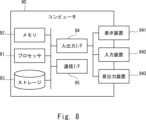
図8に示されるように、コンピュータ90は、プロセッサ91、メモリ92、ストレージ93、入出力インタフェース(入出力I/F)94、及び通信インタフェース(通信I/F)95などを備える。プロセッサ91、メモリ92、ストレージ93、入出力インタフェース94、及び通信インタフェース95は、相互にデータを送受信するためのデータ伝送路で接続されている。
プロセッサ91は、例えばCPU(Central Processing Unit)やGPU(Graphics Processing Unit)などの演算処理装置である。メモリ92は、例えばRAM(Random Access Memory)やROM(Read Only Memory)などのメモリである。ストレージ93は、例えばHDD(Hard Disk Drive)、SSD(Solid State Drive)、またはメモリカードなどの記憶装置である。また、ストレージ93は、RAMやROMなどのメモリであっても良い。
ストレージ93は、振動監視装置30が備える構成要素の機能を実現するプログラムを記憶している。プロセッサ91は、これら各プログラムを実行することで、振動監視装置30が備える構成要素の機能をそれぞれ実現する。ここで、プロセッサ91は、上記各プログラムを実行する際、これらのプログラムをメモリ92上に読み出してから実行しても良いし、メモリ92上に読み出さずに実行しても良い。また、メモリ92やストレージ93は、振動監視装置30が備える構成要素が保持する情報やデータを記憶する役割も果たす。
また、上述したプログラムは、様々なタイプの非一時的なコンピュータ可読媒体(non-transitory computer readable medium)を用いて格納され、コンピュータ(コンピュータ90を含む)に供給することができる。非一時的なコンピュータ可読媒体は、様々なタイプの実体のある記録媒体(tangible storage medium)を含む。非一時的なコンピュータ可読媒体の例は、磁気記録媒体(例えば、フレキシブルディスク、磁気テープ、ハードディスクドライブ)、光磁気記録媒体(例えば、光磁気ディスク)、CD-ROM(Compact Disc-ROM)、CD-R(CD-Recordable)、CD-R/W(CD-ReWritable)、半導体メモリ(例えば、マスクROM、PROM(Programmable ROM)、EPROM(Erasable PROM)、フラッシュROM、RAM)を含む。また、プログラムは、様々なタイプの一時的なコンピュータ可読媒体(transitory computer readable medium)によってコンピュータに供給されても良い。一時的なコンピュータ可読媒体の例は、電気信号、光信号、及び電磁波を含む。一時的なコンピュータ可読媒体は、電線及び光ファイバなどの有線通信路、又は無線通信路を介して、プログラムをコンピュータに供給できる。
入出力インタフェース94は、表示装置941、入力装置942、音出力装置943などと接続される。表示装置941は、LCD(Liquid Crystal Display)、CRT(Cathode Ray Tube)ディスプレイ、モニターのような、プロセッサ91により処理された描画データに対応する画面を表示する装置である。入力装置942は、オペレータの操作入力を受け付ける装置であり、例えば、キーボード、マウス、及びタッチセンサなどである。表示装置941及び入力装置942は一体化され、タッチパネルとして実現されていても良い。音出力装置943は、スピーカのような、プロセッサ91により処理された音響データに対応する音を音響出力する装置である。
通信インタフェース95は、外部の装置との間でデータを送受信する。例えば、通信インタフェース95は、有線通信路または無線通信路を介して外部装置と通信する。
以上、実施の形態を参照して本開示を説明したが、本開示は上述した実施の形態に限定されるものではない。本開示の構成や詳細には、本開示のスコープ内で当業者が理解し得る様々な変更をすることができる。
例えば、上述した実施の形態は、一部又は全部を相互に組み合わせて用いても良い。
例えば、上述した実施の形態は、一部又は全部を相互に組み合わせて用いても良い。
また、上述した実施の形態の一部又は全部は、以下の付記のようにも記載されうるが、以下には限られない。
(付記1)
振動発生源を管理する管理装置と、
前記振動発生源を動作させるエリアの周辺に敷設された光ファイバを用いて光ファイバセンシングを実行するセンシング装置と、
前記管理装置から、前記振動発生源の稼働状況を時系列に示す稼働データを取得する第1取得部と、
前記センシング装置から、前記光ファイバセンシングによって前記光ファイバ上の複数の測定ポイントの各々で検知された振動の振動強度の時系列変化を示すセンシングデータを取得する第2の取得部と、
前記稼働データと前記センシングデータとの時間同期を行うことにより、前記稼働データと前記センシングデータとを対応付ける処理部と、を備える、
振動監視システム。
(付記2)
前記処理部は、前記対応付けの結果に基づいて、前記複数の測定ポイントの各々で検知された振動と前記振動発生源の稼働状況との因果関係を判断する、
付記1に記載の振動監視システム。
(付記3)
前記処理部は、前記因果関係の判断結果に基づいて、前記複数の測定ポイントのうち、前記振動発生源の稼働状況の影響を受けず、かつ、閾値以上の振動強度が検知された測定ポイントを特定し、特定された測定ポイントに異常が発生している又は異常が発生する予兆があると判断する、
付記2に記載の振動監視システム。
(付記4)
前記複数の測定ポイントの各々を、当該測定ポイントで検知された振動強度と共に、地図上に重畳して表示部に表示させると共に、前記振動発生源を、前記振動発生源の稼働状況と共に、前記地図上に重畳して前記表示部に表示させる表示制御部をさらに備える、
付記1に記載の振動監視システム。
(付記5)
前記表示制御部は、前記複数の測定ポイントの各々を、当該測定ポイントで検知された振動強度のレベルに応じた態様で、前記地図上に重畳して前記表示部に表示させると共に、前記振動発生源を、前記振動発生源の稼働状況に応じた態様で、前記地図上に重畳して前記表示部に表示させる、
付記4に記載の振動監視システム。
(付記6)
前記処理部は、前記因果関係の判断結果に基づいて、前記振動発生源を制御する、
付記2に記載の振動監視システム。
(付記7)
振動発生源を管理する管理装置から、前記振動発生源の稼働状況を時系列に示す稼働データを取得する第1取得部と、
前記振動発生源を動作させるエリアの周辺に敷設された光ファイバを用いて光ファイバセンシングを実行するセンシング装置から、前記光ファイバセンシングによって前記光ファイバ上の複数の測定ポイントの各々で検知された振動の振動強度の時系列変化を示すセンシングデータを取得する第2の取得部と、
前記稼働データと前記センシングデータとの時間同期を行うことにより、前記稼働データと前記センシングデータとを対応付ける処理部と、を備える、
振動監視装置。
(付記8)
前記処理部は、前記対応付けの結果に基づいて、前記複数の測定ポイントの各々で検知された振動と前記振動発生源の稼働状況との因果関係を判断する、
付記7に記載の振動監視装置。
(付記9)
前記処理部は、前記因果関係の判断結果に基づいて、前記複数の測定ポイントのうち、前記振動発生源の稼働状況の影響を受けず、かつ、閾値以上の振動強度が検知された測定ポイントを特定し、特定された測定ポイントに異常が発生している又は異常が発生する予兆があると判断する、
付記8に記載の振動監視装置。
(付記10)
前記複数の測定ポイントの各々を、当該測定ポイントで検知された振動強度と共に、地図上に重畳して表示部に表示させると共に、前記振動発生源を、前記振動発生源の稼働状況と共に、前記地図上に重畳して前記表示部に表示させる表示制御部をさらに備える、
付記7に記載の振動監視装置。
(付記11)
前記表示制御部は、前記複数の測定ポイントの各々を、当該測定ポイントで検知された振動強度のレベルに応じた態様で、前記地図上に重畳して前記表示部に表示させると共に、前記振動発生源を、前記振動発生源の稼働状況に応じた態様で、前記地図上に重畳して前記表示部に表示させる、
付記10に記載の振動監視装置。
(付記12)
前記処理部は、前記因果関係の判断結果に基づいて、前記振動発生源を制御する、
付記8に記載の振動監視装置。
(付記13)
振動監視装置による振動監視方法であって、
振動発生源を管理する管理装置から、前記振動発生源の稼働状況を時系列に示す稼働データを取得する第1取得ステップと、
前記振動発生源を動作させるエリアの周辺に敷設された光ファイバを用いて光ファイバセンシングを実行するセンシング装置から、前記光ファイバセンシングによって前記光ファイバ上の複数の測定ポイントの各々で検知された振動の振動強度の時系列変化を示すセンシングデータを取得する第2の取得ステップと、
前記稼働データと前記センシングデータとの時間同期を行うことにより、前記稼働データと前記センシングデータとを対応付ける処理ステップと、を含む、
振動監視方法。
(付記14)
前記処理ステップでは、前対応付けの結果に基づいて、前記複数の測定ポイントの各々で検知された振動と前記振動発生源の稼働状況との因果関係を判断する、
付記13に記載の振動監視方法。
(付記15)
前記処理ステップでは、前記因果関係の判断結果に基づいて、前記複数の測定ポイントのうち、前記振動発生源の稼働状況の影響を受けず、かつ、閾値以上の振動強度が検知された測定ポイントを特定し、特定された測定ポイントに異常が発生している又は異常が発生する予兆があると判断する、
付記14に記載の振動監視方法。
(付記16)
前記複数の測定ポイントの各々を、当該測定ポイントで検知された振動強度と共に、地図上に重畳して表示部に表示させると共に、前記振動発生源を、前記振動発生源の稼働状況と共に、前記地図上に重畳して前記表示部に表示させる表示制御ステップをさらに含む、
付記13に記載の振動監視方法。
(付記17)
前記表示制御ステップでは、前記複数の測定ポイントの各々を、当該測定ポイントで検知された振動強度のレベルに応じた態様で、前記地図上に重畳して前記表示部に表示させると共に、前記振動発生源を、前記振動発生源の稼働状況に応じた態様で、前記地図上に重畳して前記表示部に表示させる、
付記16に記載の振動監視方法。
(付記18)
前記処理ステップでは、前記因果関係の判断結果に基づいて、前記振動発生源を制御する、
付記14に記載の振動監視方法。
(付記1)
振動発生源を管理する管理装置と、
前記振動発生源を動作させるエリアの周辺に敷設された光ファイバを用いて光ファイバセンシングを実行するセンシング装置と、
前記管理装置から、前記振動発生源の稼働状況を時系列に示す稼働データを取得する第1取得部と、
前記センシング装置から、前記光ファイバセンシングによって前記光ファイバ上の複数の測定ポイントの各々で検知された振動の振動強度の時系列変化を示すセンシングデータを取得する第2の取得部と、
前記稼働データと前記センシングデータとの時間同期を行うことにより、前記稼働データと前記センシングデータとを対応付ける処理部と、を備える、
振動監視システム。
(付記2)
前記処理部は、前記対応付けの結果に基づいて、前記複数の測定ポイントの各々で検知された振動と前記振動発生源の稼働状況との因果関係を判断する、
付記1に記載の振動監視システム。
(付記3)
前記処理部は、前記因果関係の判断結果に基づいて、前記複数の測定ポイントのうち、前記振動発生源の稼働状況の影響を受けず、かつ、閾値以上の振動強度が検知された測定ポイントを特定し、特定された測定ポイントに異常が発生している又は異常が発生する予兆があると判断する、
付記2に記載の振動監視システム。
(付記4)
前記複数の測定ポイントの各々を、当該測定ポイントで検知された振動強度と共に、地図上に重畳して表示部に表示させると共に、前記振動発生源を、前記振動発生源の稼働状況と共に、前記地図上に重畳して前記表示部に表示させる表示制御部をさらに備える、
付記1に記載の振動監視システム。
(付記5)
前記表示制御部は、前記複数の測定ポイントの各々を、当該測定ポイントで検知された振動強度のレベルに応じた態様で、前記地図上に重畳して前記表示部に表示させると共に、前記振動発生源を、前記振動発生源の稼働状況に応じた態様で、前記地図上に重畳して前記表示部に表示させる、
付記4に記載の振動監視システム。
(付記6)
前記処理部は、前記因果関係の判断結果に基づいて、前記振動発生源を制御する、
付記2に記載の振動監視システム。
(付記7)
振動発生源を管理する管理装置から、前記振動発生源の稼働状況を時系列に示す稼働データを取得する第1取得部と、
前記振動発生源を動作させるエリアの周辺に敷設された光ファイバを用いて光ファイバセンシングを実行するセンシング装置から、前記光ファイバセンシングによって前記光ファイバ上の複数の測定ポイントの各々で検知された振動の振動強度の時系列変化を示すセンシングデータを取得する第2の取得部と、
前記稼働データと前記センシングデータとの時間同期を行うことにより、前記稼働データと前記センシングデータとを対応付ける処理部と、を備える、
振動監視装置。
(付記8)
前記処理部は、前記対応付けの結果に基づいて、前記複数の測定ポイントの各々で検知された振動と前記振動発生源の稼働状況との因果関係を判断する、
付記7に記載の振動監視装置。
(付記9)
前記処理部は、前記因果関係の判断結果に基づいて、前記複数の測定ポイントのうち、前記振動発生源の稼働状況の影響を受けず、かつ、閾値以上の振動強度が検知された測定ポイントを特定し、特定された測定ポイントに異常が発生している又は異常が発生する予兆があると判断する、
付記8に記載の振動監視装置。
(付記10)
前記複数の測定ポイントの各々を、当該測定ポイントで検知された振動強度と共に、地図上に重畳して表示部に表示させると共に、前記振動発生源を、前記振動発生源の稼働状況と共に、前記地図上に重畳して前記表示部に表示させる表示制御部をさらに備える、
付記7に記載の振動監視装置。
(付記11)
前記表示制御部は、前記複数の測定ポイントの各々を、当該測定ポイントで検知された振動強度のレベルに応じた態様で、前記地図上に重畳して前記表示部に表示させると共に、前記振動発生源を、前記振動発生源の稼働状況に応じた態様で、前記地図上に重畳して前記表示部に表示させる、
付記10に記載の振動監視装置。
(付記12)
前記処理部は、前記因果関係の判断結果に基づいて、前記振動発生源を制御する、
付記8に記載の振動監視装置。
(付記13)
振動監視装置による振動監視方法であって、
振動発生源を管理する管理装置から、前記振動発生源の稼働状況を時系列に示す稼働データを取得する第1取得ステップと、
前記振動発生源を動作させるエリアの周辺に敷設された光ファイバを用いて光ファイバセンシングを実行するセンシング装置から、前記光ファイバセンシングによって前記光ファイバ上の複数の測定ポイントの各々で検知された振動の振動強度の時系列変化を示すセンシングデータを取得する第2の取得ステップと、
前記稼働データと前記センシングデータとの時間同期を行うことにより、前記稼働データと前記センシングデータとを対応付ける処理ステップと、を含む、
振動監視方法。
(付記14)
前記処理ステップでは、前対応付けの結果に基づいて、前記複数の測定ポイントの各々で検知された振動と前記振動発生源の稼働状況との因果関係を判断する、
付記13に記載の振動監視方法。
(付記15)
前記処理ステップでは、前記因果関係の判断結果に基づいて、前記複数の測定ポイントのうち、前記振動発生源の稼働状況の影響を受けず、かつ、閾値以上の振動強度が検知された測定ポイントを特定し、特定された測定ポイントに異常が発生している又は異常が発生する予兆があると判断する、
付記14に記載の振動監視方法。
(付記16)
前記複数の測定ポイントの各々を、当該測定ポイントで検知された振動強度と共に、地図上に重畳して表示部に表示させると共に、前記振動発生源を、前記振動発生源の稼働状況と共に、前記地図上に重畳して前記表示部に表示させる表示制御ステップをさらに含む、
付記13に記載の振動監視方法。
(付記17)
前記表示制御ステップでは、前記複数の測定ポイントの各々を、当該測定ポイントで検知された振動強度のレベルに応じた態様で、前記地図上に重畳して前記表示部に表示させると共に、前記振動発生源を、前記振動発生源の稼働状況に応じた態様で、前記地図上に重畳して前記表示部に表示させる、
付記16に記載の振動監視方法。
(付記18)
前記処理ステップでは、前記因果関係の判断結果に基づいて、前記振動発生源を制御する、
付記14に記載の振動監視方法。
本開示は、例えば、以下の用途にも利用可能である。
・工事による振動を管理する装置。例えば、工事重機等の稼働を管理する稼働管理装置。
・列車の走行による振動を管理する装置。例えば、列車の運行を管理する運行管理装置。
・工場の機械類による振動を管理する装置。例えば、工場の稼働を管理する稼働管理装置。
・車両による振動を管理する装置。例えば、道路上の車両の通行を管理する車両通行管理装置。
・人の活動に関する振動を管理するシステム。例えば、出勤管理システム。
・工事による振動を管理する装置。例えば、工事重機等の稼働を管理する稼働管理装置。
・列車の走行による振動を管理する装置。例えば、列車の運行を管理する運行管理装置。
・工場の機械類による振動を管理する装置。例えば、工場の稼働を管理する稼働管理装置。
・車両による振動を管理する装置。例えば、道路上の車両の通行を管理する車両通行管理装置。
・人の活動に関する振動を管理するシステム。例えば、出勤管理システム。
10 管理装置
20 センシング装置
30 振動監視装置
31 第1取得部
32 第2取得部
33 処理部
34 表示制御部
40 表示部
90 コンピュータ
91 プロセッサ
92 メモリ
93 ストレージ
94 入出力インタフェース
941 表示装置
942 入力装置
943 音出力装置
95 通信インタフェース
20 センシング装置
30 振動監視装置
31 第1取得部
32 第2取得部
33 処理部
34 表示制御部
40 表示部
90 コンピュータ
91 プロセッサ
92 メモリ
93 ストレージ
94 入出力インタフェース
941 表示装置
942 入力装置
943 音出力装置
95 通信インタフェース
Claims (18)
- 振動発生源を管理する管理装置と、
前記振動発生源を動作させるエリアの周辺に敷設された光ファイバを用いて光ファイバセンシングを実行するセンシング装置と、
前記管理装置から、前記振動発生源の稼働状況を時系列に示す稼働データを取得する第1取得部と、
前記センシング装置から、前記光ファイバセンシングによって前記光ファイバ上の複数の測定ポイントの各々で検知された振動の振動強度の時系列変化を示すセンシングデータを取得する第2の取得部と、
前記稼働データと前記センシングデータとの時間同期を行うことにより、前記稼働データと前記センシングデータとを対応付ける処理部と、を備える、
振動監視システム。 - 前記処理部は、前記対応付けの結果に基づいて、前記複数の測定ポイントの各々で検知された振動と前記振動発生源の稼働状況との因果関係を判断する、
請求項1に記載の振動監視システム。 - 前記処理部は、前記因果関係の判断結果に基づいて、前記複数の測定ポイントのうち、前記振動発生源の稼働状況の影響を受けず、かつ、閾値以上の振動強度が検知された測定ポイントを特定し、特定された測定ポイントに異常が発生している又は異常が発生する予兆があると判断する、
請求項2に記載の振動監視システム。 - 前記複数の測定ポイントの各々を、当該測定ポイントで検知された振動強度と共に、地図上に重畳して表示部に表示させると共に、前記振動発生源を、前記振動発生源の稼働状況と共に、前記地図上に重畳して前記表示部に表示させる表示制御部をさらに備える、
請求項1に記載の振動監視システム。 - 前記表示制御部は、前記複数の測定ポイントの各々を、当該測定ポイントで検知された振動強度のレベルに応じた態様で、前記地図上に重畳して前記表示部に表示させると共に、前記振動発生源を、前記振動発生源の稼働状況に応じた態様で、前記地図上に重畳して前記表示部に表示させる、
請求項4に記載の振動監視システム。 - 前記処理部は、前記因果関係の判断結果に基づいて、前記振動発生源を制御する、
請求項2に記載の振動監視システム。 - 振動発生源を管理する管理装置から、前記振動発生源の稼働状況を時系列に示す稼働データを取得する第1取得部と、
前記振動発生源を動作させるエリアの周辺に敷設された光ファイバを用いて光ファイバセンシングを実行するセンシング装置から、前記光ファイバセンシングによって前記光ファイバ上の複数の測定ポイントの各々で検知された振動の振動強度の時系列変化を示すセンシングデータを取得する第2の取得部と、
前記稼働データと前記センシングデータとの時間同期を行うことにより、前記稼働データと前記センシングデータとを対応付ける処理部と、を備える、
振動監視装置。 - 前記処理部は、前記対応付けの結果に基づいて、前記複数の測定ポイントの各々で検知された振動と前記振動発生源の稼働状況との因果関係を判断する、
請求項7に記載の振動監視装置。 - 前記処理部は、前記因果関係の判断結果に基づいて、前記複数の測定ポイントのうち、前記振動発生源の稼働状況の影響を受けず、かつ、閾値以上の振動強度が検知された測定ポイントを特定し、特定された測定ポイントに異常が発生している又は異常が発生する予兆があると判断する、
請求項8に記載の振動監視装置。 - 前記複数の測定ポイントの各々を、当該測定ポイントで検知された振動強度と共に、地図上に重畳して表示部に表示させると共に、前記振動発生源を、前記振動発生源の稼働状況と共に、前記地図上に重畳して前記表示部に表示させる表示制御部をさらに備える、
請求項7に記載の振動監視装置。 - 前記表示制御部は、前記複数の測定ポイントの各々を、当該測定ポイントで検知された振動強度のレベルに応じた態様で、前記地図上に重畳して前記表示部に表示させると共に、前記振動発生源を、前記振動発生源の稼働状況に応じた態様で、前記地図上に重畳して前記表示部に表示させる、
請求項10に記載の振動監視装置。 - 前記処理部は、前記因果関係の判断結果に基づいて、前記振動発生源を制御する、
請求項8に記載の振動監視装置。 - 振動監視装置による振動監視方法であって、
振動発生源を管理する管理装置から、前記振動発生源の稼働状況を時系列に示す稼働データを取得する第1取得ステップと、
前記振動発生源を動作させるエリアの周辺に敷設された光ファイバを用いて光ファイバセンシングを実行するセンシング装置から、前記光ファイバセンシングによって前記光ファイバ上の複数の測定ポイントの各々で検知された振動の振動強度の時系列変化を示すセンシングデータを取得する第2の取得ステップと、
前記稼働データと前記センシングデータとの時間同期を行うことにより、前記稼働データと前記センシングデータとを対応付ける処理ステップと、を含む、
振動監視方法。 - 前記処理ステップでは、前対応付けの結果に基づいて、前記複数の測定ポイントの各々で検知された振動と前記振動発生源の稼働状況との因果関係を判断する、
請求項13に記載の振動監視方法。 - 前記処理ステップでは、前記因果関係の判断結果に基づいて、前記複数の測定ポイントのうち、前記振動発生源の稼働状況の影響を受けず、かつ、閾値以上の振動強度が検知された測定ポイントを特定し、特定された測定ポイントに異常が発生している又は異常が発生する予兆があると判断する、
請求項14に記載の振動監視方法。 - 前記複数の測定ポイントの各々を、当該測定ポイントで検知された振動強度と共に、地図上に重畳して表示部に表示させると共に、前記振動発生源を、前記振動発生源の稼働状況と共に、前記地図上に重畳して前記表示部に表示させる表示制御ステップをさらに含む、
請求項13に記載の振動監視方法。 - 前記表示制御ステップでは、前記複数の測定ポイントの各々を、当該測定ポイントで検知された振動強度のレベルに応じた態様で、前記地図上に重畳して前記表示部に表示させると共に、前記振動発生源を、前記振動発生源の稼働状況に応じた態様で、前記地図上に重畳して前記表示部に表示させる、
請求項16に記載の振動監視方法。 - 前記処理ステップでは、前記因果関係の判断結果に基づいて、前記振動発生源を制御する、
請求項14に記載の振動監視方法。
Priority Applications (2)
| Application Number | Priority Date | Filing Date | Title |
|---|---|---|---|
| JP2025525452A JPWO2024252476A1 (ja) | 2023-06-05 | 2023-06-05 | |
| PCT/JP2023/020829 WO2024252476A1 (ja) | 2023-06-05 | 2023-06-05 | 振動監視システム、振動監視装置、及び振動監視方法 |
Applications Claiming Priority (1)
| Application Number | Priority Date | Filing Date | Title |
|---|---|---|---|
| PCT/JP2023/020829 WO2024252476A1 (ja) | 2023-06-05 | 2023-06-05 | 振動監視システム、振動監視装置、及び振動監視方法 |
Publications (1)
| Publication Number | Publication Date |
|---|---|
| WO2024252476A1 true WO2024252476A1 (ja) | 2024-12-12 |
Family
ID=93795135
Family Applications (1)
| Application Number | Title | Priority Date | Filing Date |
|---|---|---|---|
| PCT/JP2023/020829 Ceased WO2024252476A1 (ja) | 2023-06-05 | 2023-06-05 | 振動監視システム、振動監視装置、及び振動監視方法 |
Country Status (2)
| Country | Link |
|---|---|
| JP (1) | JPWO2024252476A1 (ja) |
| WO (1) | WO2024252476A1 (ja) |
Citations (2)
| Publication number | Priority date | Publication date | Assignee | Title |
|---|---|---|---|---|
| WO2021010251A1 (ja) * | 2019-07-17 | 2021-01-21 | 日本電気株式会社 | 光ファイバセンシングシステム、光ファイバセンシング機器、及び異常判断方法 |
| WO2022034748A1 (ja) * | 2020-08-13 | 2022-02-17 | 日本電気株式会社 | 水中騒音監視装置、水中騒音監視方法及び記録媒体 |
-
2023
- 2023-06-05 WO PCT/JP2023/020829 patent/WO2024252476A1/ja not_active Ceased
- 2023-06-05 JP JP2025525452A patent/JPWO2024252476A1/ja active Pending
Patent Citations (2)
| Publication number | Priority date | Publication date | Assignee | Title |
|---|---|---|---|---|
| WO2021010251A1 (ja) * | 2019-07-17 | 2021-01-21 | 日本電気株式会社 | 光ファイバセンシングシステム、光ファイバセンシング機器、及び異常判断方法 |
| WO2022034748A1 (ja) * | 2020-08-13 | 2022-02-17 | 日本電気株式会社 | 水中騒音監視装置、水中騒音監視方法及び記録媒体 |
Also Published As
| Publication number | Publication date |
|---|---|
| JPWO2024252476A1 (ja) | 2024-12-12 |
Similar Documents
| Publication | Publication Date | Title |
|---|---|---|
| US20240271969A1 (en) | Utility pole deterioration detection system, utility pole deterioration detection apparatus, utility pole deterioration detection method, and non-transitory computer readable medium | |
| WO2020116030A1 (ja) | 道路監視システム、道路監視装置、道路監視方法、及び非一時的なコンピュータ可読媒体 | |
| US12154007B2 (en) | Fiber sensing on roadside applications | |
| JP2024014948A (ja) | 道路監視システム、道路監視装置、道路監視方法、及びプログラム | |
| JP7235115B2 (ja) | 光ファイバセンシングシステム、光ファイバセンシング機器、及び異常判断方法 | |
| WO2024004119A1 (ja) | センシングシステム、センシング機器、及びセンシング方法 | |
| CN118774973A (zh) | 大煤柱掘进的监控方法及装置 | |
| JP7533566B2 (ja) | 監視システム、監視装置、及び監視方法 | |
| US20220277641A1 (en) | Optical fiber sensing system, optical fiber sensing equipment, and rescue request detection method | |
| WO2024252476A1 (ja) | 振動監視システム、振動監視装置、及び振動監視方法 | |
| US20220326070A1 (en) | Fiber optic sensing for reduced field work conflicts | |
| WO2022113252A1 (ja) | 位置特定システム、振動発生器、及び位置特定方法 | |
| US20210372828A1 (en) | Civil engineering structure monitoring system, civil engineering structure monitoring apparatus, civil engineering structure monitoring method, and non-transitory computer-readable medium | |
| WO2020116031A1 (ja) | 線路監視システム、線路監視装置、線路監視方法、及び非一時的なコンピュータ可読媒体 | |
| JP7416233B2 (ja) | 異常検出システム、異常検出装置、異常検出方法、及びプログラム | |
| US20240361178A1 (en) | Monitoring system, monitoring apparatus, and monitoring method | |
| JP2021034917A (ja) | センサ設置支援装置、センサ設置支援方法およびプログラム | |
| CN110095182A (zh) | 隧道噪声检测装置及方法 | |
| US20230070029A1 (en) | Detection system, detection device, and detection method | |
| US20230417593A1 (en) | Optical fiber sensing system, optical fiber sensing method, and optical fiber sensing device | |
| US20230128841A1 (en) | Damaged part identifying apparatus, method and program | |
| US20230081172A1 (en) | Power failure detection system, power failure detection device, and power failure detection method | |
| JP7525082B1 (ja) | 設備監視システム、及び設備監視方法 | |
| CN118585744B (zh) | 一种数据处理方法、装置、机械设备和存储介质 | |
| JP2021033731A (ja) | 被災把握システム、処理装置及びプログラム |
Legal Events
| Date | Code | Title | Description |
|---|---|---|---|
| 121 | Ep: the epo has been informed by wipo that ep was designated in this application |
Ref document number: 23940583 Country of ref document: EP Kind code of ref document: A1 |
|
| ENP | Entry into the national phase |
Ref document number: 2025525452 Country of ref document: JP Kind code of ref document: A |
|
| NENP | Non-entry into the national phase |
Ref country code: DE |