WO2024252479A1 - Dispositif de traitement de journal, procédé de traitement de journal et programme - Google Patents
Dispositif de traitement de journal, procédé de traitement de journal et programme Download PDFInfo
- Publication number
- WO2024252479A1 WO2024252479A1 PCT/JP2023/020845 JP2023020845W WO2024252479A1 WO 2024252479 A1 WO2024252479 A1 WO 2024252479A1 JP 2023020845 W JP2023020845 W JP 2023020845W WO 2024252479 A1 WO2024252479 A1 WO 2024252479A1
- Authority
- WO
- WIPO (PCT)
- Prior art keywords
- log
- layer
- causal model
- logs
- observation data
- Prior art date
- Legal status (The legal status is an assumption and is not a legal conclusion. Google has not performed a legal analysis and makes no representation as to the accuracy of the status listed.)
- Ceased
Links
Images
Classifications
-
- H—ELECTRICITY
- H04—ELECTRIC COMMUNICATION TECHNIQUE
- H04L—TRANSMISSION OF DIGITAL INFORMATION, e.g. TELEGRAPHIC COMMUNICATION
- H04L41/00—Arrangements for maintenance, administration or management of data switching networks, e.g. of packet switching networks
- H04L41/16—Arrangements for maintenance, administration or management of data switching networks, e.g. of packet switching networks using machine learning or artificial intelligence
Definitions
- the present invention relates to a technology for estimating abnormal locations in a communication network based on logs collected from the communication network.
- Non-Patent Documents 1 and 2 For telecommunications carriers, it is important to understand the status of anomalies and respond quickly to any anomalies that occur within a communications network. In this context, research is being conducted on early detection of anomalies within communications networks and on estimating the location of anomalies (Non-Patent Documents 1 and 2).
- Non-Patent Document 3 A method has been proposed for estimating the location of an anomaly, which uses a Bayesian network to model (called a causal model) the relationship between the location of an anomaly and the changes in data (called observed data) in the communication network that are caused by the anomaly, and estimates the location of the anomaly from the observed data when the anomaly occurs.
- non-patent document 3 based on the assumption that a router abnormality only affects the observation data of routers that are physically adjacent to the abnormal router, a causal model is constructed for devices in the communication network, consisting of device nodes that indicate the state of each device and observation nodes that indicate whether a link-down related log has been generated from that device, and the location of the abnormality is determined.
- Non-Patent Document 4 also uses various logs other than the link-down of the physical opposing device to estimate the location of an anomaly in a variety of anomalies within a communication network.
- devices such as routers output different logs for each layer where an anomaly has occurred, such as logs showing the status of the device, such as the CPU, memory, and interface module (called the device layer), logs showing the status of the interface connection with the physically connected opposing device (called the physical layer), and logs showing the status of the logically connected device (called the logical layer).
- a causal model is created using the operator's knowledge for each event that could be the cause of the anomaly pattern or the generated log, and the location of the anomaly is estimated.
- Non-Patent Document 3 creates a causal model based on the assumption that a router anomaly only affects the observation data of routers that are physically adjacent to the router in an anomalous state, so a causal model can be constructed if there is information on the connection relationships.
- Non-Patent Document 3 the log used is a log related to a link down in the physical layer. Therefore, in the event of a physical layer failure, communication is lost due to the failure, so a link down log is generated from both the router where the failure occurred and its adjacent router; alternatively, in the event of a logical layer failure, a link down log is generated from a device that is not physically opposed but is logically connected. Therefore, there is a problem in that it may not be possible to estimate the location of the abnormality.
- a log collection unit that collects logs from a communication network; a log selection unit that determines a layer to which each log collected by the log collection unit belongs, and selects a log to be used for estimating a failure location using a causal model based on the layer.
- the disclosed technology provides a technique for improving the accuracy of estimating abnormal locations within a communication network.
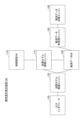
- FIG. 1 is a diagram illustrating an example of the configuration of an abnormality location estimating device 100.
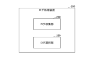
- FIG. FIG. 2 is a diagram illustrating an example of the configuration of a log processing device 200.
- FIG. 2 illustrates an example of a hardware configuration of the apparatus.
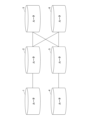
- FIG. 1 illustrates an example of a communication network.
- FIG. 5 shows an example of a causal model based on FIG. 4 .
- FIG. 2 is a diagram illustrating an example of a connection relationship in a logical layer.
- FIG. 7 is a diagram showing an example of a causal model based on FIG. 6 .
- observation data collection engine 160 the observation data preprocessing engine 130, the causal model construction engine 110, and the causal model inference engine 120 may be referred to as the observation data collection unit 160, the observation data preprocessing unit 130, the causal model construction unit 110, and the causal model inference unit 120, respectively.
- observation data collection engine 160, the observation data preprocessing engine 130, the causal model construction engine 110, and the causal model inference engine 120 may be referred to as the observation data collection circuit 160, the observation data preprocessing circuit 130, the causal model construction circuit 110, and the causal model inference circuit 120, respectively.
- the abnormality location estimation device 100 may also be called a log processing device.
- the observation data collection engine 160 and the observation data pre-processing engine 130 may also be called a log collection unit and a log selection unit, respectively.
- the operation of the abnormality location estimation device 100 is outlined below.
- the observation data collection engine 160 collects observation data (such as logs generated by devices) from the communication network.
- the observation data pre-processing engine 130 determines the layer to which the logs collected by the observation data collection engine 160 belong, extracts only the logs from the lowest layer, and stores the extracted logs in the observation data DB 140.
- the causal model construction engine 110 constructs a causal model using the physical or logical node connections stored in the connection relationship DB 170 as input, depending on the layer to which the logs stored in the observation data DB 140 belong.
- the causal model inference engine 120 determines the value of the observation node based on the occurrence status of the logs stored in the observation data DB 140, estimates the location of the anomaly, and outputs the estimated result of the anomaly to the output interface 150.
- the output interface 150 displays to the user the location of an anomaly in the communication network and the maximum posterior probability at that time.
- the output interface 150 can add a node to the causal graph and also allow the user to correct any changes in causal relationships that result from this.
- the abnormality location estimation device 100 may be a single device (computer) or may be composed of multiple devices.
- observation data collection engine 160 and the observation data pre-processing engine 130 may form a single device, which may be called a log processing device.
- the log collection unit 210 collects logs from a communication network.
- the log selection unit 220 determines the layer to which each log collected by the log collection unit 210 belongs, and selects logs to be used for estimating the location of a fault using a causal model based on the layer. For example, the log selection unit 220 selects only the logs of the lowest layer out of the one or more determined layers as logs to be used for estimating the location of a fault using a causal model.
- Any of the devices described in this specification can be realized, for example, by causing a computer to execute a program.
- This computer may be a physical computer or a virtual machine on the cloud.
- the device can be realized by using hardware resources such as a CPU and memory built into a computer to execute a program corresponding to the processing performed by the device.
- the program can be recorded on a computer-readable recording medium (such as a portable memory) and then stored or distributed.
- the program can also be provided via a network such as the Internet or email.
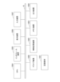
- FIG. 3 is a diagram showing an example of the hardware configuration of the computer.
- the computer in FIG. 3 has a drive device 1000, an auxiliary storage device 1002, a memory device 1003, a CPU 1004, an interface device 1005, a display device 1006, an input device 1007, an output device 1008, etc., all of which are interconnected by a bus BS.
- the program that realizes the processing on the computer is provided by a recording medium 1001, such as a CD-ROM or a memory card.
- a recording medium 1001 storing the program is set in the drive device 1000, the program is installed from the recording medium 1001 via the drive device 1000 into the auxiliary storage device 1002.
- the program does not necessarily have to be installed from the recording medium 1001, but may be downloaded from another computer via a network.
- the auxiliary storage device 1002 stores the installed program as well as necessary files, data, etc.
- the memory device 1003 When an instruction to start a program is received, the memory device 1003 reads out and stores the program from the auxiliary storage device 1002.
- the CPU 1004 realizes the functions related to the device in accordance with the program stored in the memory device 1003.
- the interface device 1005 is used as an interface for connecting to a network.
- the display device 1006 displays a GUI (Graphical User Interface) based on a program.
- the input device 1007 is composed of a keyboard and mouse, buttons, a touch panel, or the like, and is used to input various operational instructions.
- the output device 1008 outputs the results of calculations.
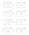
- FIG. 4 shows an example of a communications network from which the observation data collection engine 160 collects observation data. This corresponds to the connection relationship at the physical layer.
- this communications network is a network in which routers 1 to 6 are connected as shown. For example, router 1 and router 2 are directly connected, and are adjacent to each other. Router 1 and router 4 are not directly connected, and are not adjacent to each other.
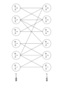
- the causal model construction engine 110 constructs the causal model shown in FIG. 5 for the communication network (physical layer network) shown in FIG. 4 based on the knowledge of an expert operator, etc.
- the causal model consists of device nodes that represent the state of each device (router) in the communication network, and observation nodes that represent whether a log (e.g., syslog related to link down) has been generated from the device. In other words, the observation nodes represent the observation results of each device.
- the causal model may also be called a Bayesian network.
- Router 1 which is an equipment node
- Routers 1 and 2 which are observation nodes. This indicates that if an abnormality occurs in Router 1, it may affect the observation data of Router 1 and the observation data of Router 2.
- router 2 which is an equipment node
- routers 1, 2, 3, and 6 which are observation nodes. This indicates that if an abnormality occurs in router 2, it may affect the observation data of routers 1, 2, 3, and 6.
- the observation data pre-processing engine 130 takes into consideration the layer of the logs collected by the observation data collection engine 160, selects logs to be used for estimating anomaly locations using a causal model from the collected logs, and stores the selected logs in the observation data DB 140. As described above, only logs at the lowest layer are extracted, and the extracted logs are stored in the observation data DB 140.
- the logs selected by the observation data pre-processing engine 130 are not limited to logs from the lowest layer.
- the observation data pre-processing engine 130 may select logs from multiple layers (e.g., the lowest layer and the second lowest layer).
- the layers increase from “physical” to “logical”, similar to the general concept of layers.
- equipment is a lower layer than “physical”.
- the definition of high/low layers may be set arbitrarily.
- the abnormality location estimation device 100 does not use the physical layer log or the logical layer log, but only uses the equipment layer log to determine the abnormality location.
- the observation data preprocessing engine 130 extracts only the equipment layer log, which is the lowest layer, from the equipment layer log, physical layer log, and logical layer log, and stores it in the observation data DB 140.
- the abnormality location estimation device 100 does not use the logical layer log, but only the physical layer log to determine the abnormality location.
- the observation data preprocessing engine 130 extracts only the physical layer log, which is the lowest layer, from the physical layer log and the logical layer log, and stores it in the observation data DB 140.
- the anomaly location estimation device 100 uses the log in the logical layer to determine the abnormality location.
- the observation data preprocessing engine 130 stores only the log in the logical layer in the observation data DB 140.
- the observation data pre-processing engine 130 holds a table that associates the type of log with the layer, and determines the layer of a new log by referencing this table.
- the observation data preprocessing engine 130 holds a trained model that has learned the relationship between a log and the layer to which the log belongs, and by inputting a log into the model, the layer of the log can be obtained as an output from the model.
- the causal model construction engine 110 constructs a causal model based on the logs to be used. If the logs to be used are device layer logs or physical layer logs, the causal model is constructed based on the physical connection relationships, as in Non-Patent Document 3.
- the method of constructing the causal model in this case is as described with reference to Figures 4 and 5, and in both cases where the log used is an equipment layer log and where the log used is a physical layer log, a causal model such as that shown in Figure 5 is constructed. Note that, here, an example is assumed in which the causal model when the log used is an equipment layer log is the same as the causal model when the log used is a physical layer log, but there are also cases in which they are different.
- the causal model construction engine 110 constructs a causal model based on the connection relationships in the logical layer read from the connection relationship DB 170.
- the above method makes it possible to build a causal model based only on the connection relationships, and to estimate various anomalies, from anomalies in the device layer to anomalies in the logical layer, thereby improving the accuracy of anomaly location estimation.
- Non-Patent Document 3 a causal model is constructed from the connection relationships between devices, so a causal model like the one shown in Figure 5 is created.
- FIG. 6 is a diagram showing an example of the connection relationship in the logical layer of the communication network according to this embodiment. As shown in FIG. 6, unlike the connection relationship in the physical layer (or device layer) shown in FIG. 4, for example, router 1 and router 3 are directly connected. This direct connection is a logical direct connection.
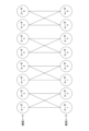
- Figure 7 shows an example of a causal model constructed based on the connection relationships in the logical layer shown in Figure 6.
- router 1 which is an equipment node
- routers 1 and 3 which are observation nodes. This indicates that if an abnormality occurs in router 1, it may affect the observation data of routers 1 and 3.
- the abnormality in this case is an abnormality related to the logical layer log.
- the values of the observation nodes are defined as follows for the constructed causal model.
- an equipment node is denoted by x i
- an observation node is denoted by y i , where i ⁇ (1, . . . N), where N is the number of equipment.
- Each x i takes a value of 0 (normal state) or 1 (abnormal state). It is possible for it to take multiple values, 3 or more, instead of the two values 0 and 1. In that case, the minimum value is the normal state, the maximum value is the abnormal state, and the value c between them is defined as a value that indicates abnormality at the rate of "c/(maximum value - minimum value)".
- Each yi takes a value of 0 or 1, and indicates that a log has occurred at the i-th router.
- the log used here is only the log of the original layer (the log of the lowest layer). It is also possible to take multiple values, 3 or more, instead of the two values 0 and 1, in which case the value is defined as the number of logs that have occurred at the i-th router.
- the inference itself using the causal model is the same as the method in Non-Patent Document 3, and inference is performed by defining the prior probability P(x i ) and the conditional probability P(y j
- the observation data preprocessing engine 130 determines the layer to which the collected logs belong and extracts only the logs from the lowest layer, thereby improving the accuracy of estimating abnormal locations within the communication network.
- Additional Notes Memory, at least one processor coupled to the memory; Including, The processor, Collect logs from communication networks, a layer to which each of the collected logs belongs is determined, and a log to be used for estimating a failure location using a causal model is selected based on the layer.
- the log processing device includes, the processor, selects only a log of a lowest layer among the determined one or more layers as a log to be used for estimating a failure location using a causal model.
- Additional Note 3 The log processing device according to claim 1 or 2, wherein the processor constructs a causal model based on a connection relationship between nodes in a layer to which the selected log belongs.
- a log processing method executed by a log processing device comprising: A log collection step of collecting logs from a communication network; a log selection step of determining a layer to which each log collected by the log collection step belongs, and selecting a log to be used for estimating a failure location using a causal model based on the layer.
- a non-transitory storage medium storing a program for causing a computer to function as each unit in the log processing device according to any one of claims 1 to 4.
- Anomaly location estimation device 110 Causal model construction engine 120 Causal model inference engine 130 Observation data pre-processing engine 140 Observation data DB 150 Output interface 160 Observation data collection engine 170 Connection relationship DB 200 Log collection device 210 Log collection unit 220 Log selection unit 220 1000 Drive device 1001 Recording medium 1002 Auxiliary storage device 1003 Memory device 1004 CPU 1005 Interface device 1006 Display device 1007 Input device 1008 Output device
Landscapes
- Engineering & Computer Science (AREA)
- Artificial Intelligence (AREA)
- Computer Vision & Pattern Recognition (AREA)
- Databases & Information Systems (AREA)
- Evolutionary Computation (AREA)
- Medical Informatics (AREA)
- Software Systems (AREA)
- Computer Networks & Wireless Communication (AREA)
- Signal Processing (AREA)
- Data Exchanges In Wide-Area Networks (AREA)
Abstract
La présente invention porte sur un dispositif de traitement de journal qui comprend une unité de collecte de journal qui collecte des journaux à partir d'un réseau de communication, et une unité de sélection de journal qui détermine une couche à laquelle appartient chaque journal collecté par l'unité de collecte de journal, et sélectionne, sur la base des couches, un journal à utiliser pour une estimation d'emplacement de défaillance à l'aide d'un modèle causal.
Priority Applications (2)
| Application Number | Priority Date | Filing Date | Title |
|---|---|---|---|
| PCT/JP2023/020845 WO2024252479A1 (fr) | 2023-06-05 | 2023-06-05 | Dispositif de traitement de journal, procédé de traitement de journal et programme |
| JP2025525455A JPWO2024252479A1 (fr) | 2023-06-05 | 2023-06-05 |
Applications Claiming Priority (1)
| Application Number | Priority Date | Filing Date | Title |
|---|---|---|---|
| PCT/JP2023/020845 WO2024252479A1 (fr) | 2023-06-05 | 2023-06-05 | Dispositif de traitement de journal, procédé de traitement de journal et programme |
Publications (1)
| Publication Number | Publication Date |
|---|---|
| WO2024252479A1 true WO2024252479A1 (fr) | 2024-12-12 |
Family
ID=93795190
Family Applications (1)
| Application Number | Title | Priority Date | Filing Date |
|---|---|---|---|
| PCT/JP2023/020845 Ceased WO2024252479A1 (fr) | 2023-06-05 | 2023-06-05 | Dispositif de traitement de journal, procédé de traitement de journal et programme |
Country Status (2)
| Country | Link |
|---|---|
| JP (1) | JPWO2024252479A1 (fr) |
| WO (1) | WO2024252479A1 (fr) |
Citations (3)
| Publication number | Priority date | Publication date | Assignee | Title |
|---|---|---|---|---|
| JP2002354038A (ja) * | 2001-05-23 | 2002-12-06 | Fujitsu Ltd | レイヤ型ネットワークの管理システム |
| US20190165988A1 (en) * | 2017-11-27 | 2019-05-30 | Google Llc | Real-time probabilistic root cause correlation of network failures |
| WO2021079521A1 (fr) * | 2019-10-25 | 2021-04-29 | 日本電信電話株式会社 | Dispositif, procédé et programme de génération de règle |
-
2023
- 2023-06-05 JP JP2025525455A patent/JPWO2024252479A1/ja active Pending
- 2023-06-05 WO PCT/JP2023/020845 patent/WO2024252479A1/fr not_active Ceased
Patent Citations (3)
| Publication number | Priority date | Publication date | Assignee | Title |
|---|---|---|---|---|
| JP2002354038A (ja) * | 2001-05-23 | 2002-12-06 | Fujitsu Ltd | レイヤ型ネットワークの管理システム |
| US20190165988A1 (en) * | 2017-11-27 | 2019-05-30 | Google Llc | Real-time probabilistic root cause correlation of network failures |
| WO2021079521A1 (fr) * | 2019-10-25 | 2021-04-29 | 日本電信電話株式会社 | Dispositif, procédé et programme de génération de règle |
Also Published As
| Publication number | Publication date |
|---|---|
| JPWO2024252479A1 (fr) | 2024-12-12 |
Similar Documents
| Publication | Publication Date | Title |
|---|---|---|
| US11818014B2 (en) | Multi-baseline unsupervised security-incident and network behavioral anomaly detection in cloud-based compute environments | |
| CN1665205B (zh) | 故障检测和诊断 | |
| US7631222B2 (en) | Method and apparatus for correlating events in a network | |
| US7113988B2 (en) | Proactive on-line diagnostics in a manageable network | |
| US9025434B2 (en) | Automated datacenter network failure mitigation | |
| US8583779B2 (en) | Root cause analysis approach with candidate elimination using network virtualization | |
| EP3338191B1 (fr) | Structure de diagnostic dans des systèmes informatiques | |
| US8423826B2 (en) | Method, apparatus and system for displaying result of failure root cause analysis | |
| US10728085B1 (en) | Model-based network management | |
| CN113973042B (zh) | 用于网络问题的根本原因分析的方法和系统 | |
| CN118119926A (zh) | 基于候选运行手册的结果与事件的补救的相关性推荐候选运行手册 | |
| US20090063902A1 (en) | Preliminary Classification of Events to Facilitate Cause-Based Analysis | |
| WO2021002298A1 (fr) | Dispositif d'estimation d'influence de défaillance, procédé d'estimation d'influence de défaillance, et programme | |
| CN116418653A (zh) | 基于多指标根因定位算法的故障定位方法及装置 | |
| WO2020214408A1 (fr) | Mode de temporisation pour dispositifs de mémoire | |
| JP7414135B2 (ja) | モデル構築装置、推定装置、モデル構築方法、推定方法及びプログラム | |
| US7844443B2 (en) | Network subscriber experience modeling | |
| JP2018124829A (ja) | 状態判定装置、状態判定方法及びプログラム | |
| Matsuo et al. | Root-cause diagnosis for rare failures using bayesian network with dynamic modification | |
| WO2024252479A1 (fr) | Dispositif de traitement de journal, procédé de traitement de journal et programme | |
| WO2025041236A1 (fr) | Dispositif de traitement de journal, procédé de traitement de journal et programme | |
| CN117336228A (zh) | 一种基于机器学习的igp仿真推荐方法、装置及介质 | |
| JP7720005B2 (ja) | 異常箇所推定装置、異常箇所推定方法、及びプログラム | |
| Schoenfisch et al. | Root cause analysis through abduction in markov logic networks | |
| US7558770B2 (en) | Method and system to detect application non-conformance |
Legal Events
| Date | Code | Title | Description |
|---|---|---|---|
| 121 | Ep: the epo has been informed by wipo that ep was designated in this application |
Ref document number: 23940586 Country of ref document: EP Kind code of ref document: A1 |
|
| ENP | Entry into the national phase |
Ref document number: 2025525455 Country of ref document: JP Kind code of ref document: A |
|
| WWE | Wipo information: entry into national phase |
Ref document number: 2025525455 Country of ref document: JP |
|
| NENP | Non-entry into the national phase |
Ref country code: DE |