WO2024252479A1 - ログ処理装置、ログ処理方法、及びプログラム - Google Patents
ログ処理装置、ログ処理方法、及びプログラム Download PDFInfo
- Publication number
- WO2024252479A1 WO2024252479A1 PCT/JP2023/020845 JP2023020845W WO2024252479A1 WO 2024252479 A1 WO2024252479 A1 WO 2024252479A1 JP 2023020845 W JP2023020845 W JP 2023020845W WO 2024252479 A1 WO2024252479 A1 WO 2024252479A1
- Authority
- WO
- WIPO (PCT)
- Prior art keywords
- log
- layer
- causal model
- logs
- observation data
- Prior art date
- Legal status (The legal status is an assumption and is not a legal conclusion. Google has not performed a legal analysis and makes no representation as to the accuracy of the status listed.)
- Ceased
Links
Images
Classifications
-
- H—ELECTRICITY
- H04—ELECTRIC COMMUNICATION TECHNIQUE
- H04L—TRANSMISSION OF DIGITAL INFORMATION, e.g. TELEGRAPHIC COMMUNICATION
- H04L41/00—Arrangements for maintenance, administration or management of data switching networks, e.g. of packet switching networks
- H04L41/16—Arrangements for maintenance, administration or management of data switching networks, e.g. of packet switching networks using machine learning or artificial intelligence
Definitions
- the present invention relates to a technology for estimating abnormal locations in a communication network based on logs collected from the communication network.
- Non-Patent Documents 1 and 2 For telecommunications carriers, it is important to understand the status of anomalies and respond quickly to any anomalies that occur within a communications network. In this context, research is being conducted on early detection of anomalies within communications networks and on estimating the location of anomalies (Non-Patent Documents 1 and 2).
- Non-Patent Document 3 A method has been proposed for estimating the location of an anomaly, which uses a Bayesian network to model (called a causal model) the relationship between the location of an anomaly and the changes in data (called observed data) in the communication network that are caused by the anomaly, and estimates the location of the anomaly from the observed data when the anomaly occurs.
- non-patent document 3 based on the assumption that a router abnormality only affects the observation data of routers that are physically adjacent to the abnormal router, a causal model is constructed for devices in the communication network, consisting of device nodes that indicate the state of each device and observation nodes that indicate whether a link-down related log has been generated from that device, and the location of the abnormality is determined.
- Non-Patent Document 4 also uses various logs other than the link-down of the physical opposing device to estimate the location of an anomaly in a variety of anomalies within a communication network.
- devices such as routers output different logs for each layer where an anomaly has occurred, such as logs showing the status of the device, such as the CPU, memory, and interface module (called the device layer), logs showing the status of the interface connection with the physically connected opposing device (called the physical layer), and logs showing the status of the logically connected device (called the logical layer).
- a causal model is created using the operator's knowledge for each event that could be the cause of the anomaly pattern or the generated log, and the location of the anomaly is estimated.
- Non-Patent Document 3 creates a causal model based on the assumption that a router anomaly only affects the observation data of routers that are physically adjacent to the router in an anomalous state, so a causal model can be constructed if there is information on the connection relationships.
- Non-Patent Document 3 the log used is a log related to a link down in the physical layer. Therefore, in the event of a physical layer failure, communication is lost due to the failure, so a link down log is generated from both the router where the failure occurred and its adjacent router; alternatively, in the event of a logical layer failure, a link down log is generated from a device that is not physically opposed but is logically connected. Therefore, there is a problem in that it may not be possible to estimate the location of the abnormality.
- a log collection unit that collects logs from a communication network; a log selection unit that determines a layer to which each log collected by the log collection unit belongs, and selects a log to be used for estimating a failure location using a causal model based on the layer.
- the disclosed technology provides a technique for improving the accuracy of estimating abnormal locations within a communication network.
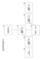
- FIG. 1 is a diagram illustrating an example of the configuration of an abnormality location estimating device 100.
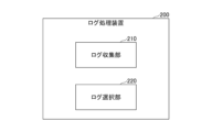
- FIG. FIG. 2 is a diagram illustrating an example of the configuration of a log processing device 200.
- FIG. 2 illustrates an example of a hardware configuration of the apparatus.
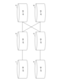
- FIG. 1 illustrates an example of a communication network.
- FIG. 5 shows an example of a causal model based on FIG. 4 .
- FIG. 2 is a diagram illustrating an example of a connection relationship in a logical layer.
- FIG. 7 is a diagram showing an example of a causal model based on FIG. 6 .
- observation data collection engine 160 the observation data preprocessing engine 130, the causal model construction engine 110, and the causal model inference engine 120 may be referred to as the observation data collection unit 160, the observation data preprocessing unit 130, the causal model construction unit 110, and the causal model inference unit 120, respectively.
- observation data collection engine 160, the observation data preprocessing engine 130, the causal model construction engine 110, and the causal model inference engine 120 may be referred to as the observation data collection circuit 160, the observation data preprocessing circuit 130, the causal model construction circuit 110, and the causal model inference circuit 120, respectively.
- the abnormality location estimation device 100 may also be called a log processing device.
- the observation data collection engine 160 and the observation data pre-processing engine 130 may also be called a log collection unit and a log selection unit, respectively.
- the operation of the abnormality location estimation device 100 is outlined below.
- the observation data collection engine 160 collects observation data (such as logs generated by devices) from the communication network.
- the observation data pre-processing engine 130 determines the layer to which the logs collected by the observation data collection engine 160 belong, extracts only the logs from the lowest layer, and stores the extracted logs in the observation data DB 140.
- the causal model construction engine 110 constructs a causal model using the physical or logical node connections stored in the connection relationship DB 170 as input, depending on the layer to which the logs stored in the observation data DB 140 belong.
- the causal model inference engine 120 determines the value of the observation node based on the occurrence status of the logs stored in the observation data DB 140, estimates the location of the anomaly, and outputs the estimated result of the anomaly to the output interface 150.
- the output interface 150 displays to the user the location of an anomaly in the communication network and the maximum posterior probability at that time.
- the output interface 150 can add a node to the causal graph and also allow the user to correct any changes in causal relationships that result from this.
- the abnormality location estimation device 100 may be a single device (computer) or may be composed of multiple devices.
- observation data collection engine 160 and the observation data pre-processing engine 130 may form a single device, which may be called a log processing device.
- the log collection unit 210 collects logs from a communication network.
- the log selection unit 220 determines the layer to which each log collected by the log collection unit 210 belongs, and selects logs to be used for estimating the location of a fault using a causal model based on the layer. For example, the log selection unit 220 selects only the logs of the lowest layer out of the one or more determined layers as logs to be used for estimating the location of a fault using a causal model.
- Any of the devices described in this specification can be realized, for example, by causing a computer to execute a program.
- This computer may be a physical computer or a virtual machine on the cloud.
- the device can be realized by using hardware resources such as a CPU and memory built into a computer to execute a program corresponding to the processing performed by the device.
- the program can be recorded on a computer-readable recording medium (such as a portable memory) and then stored or distributed.
- the program can also be provided via a network such as the Internet or email.
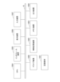
- FIG. 3 is a diagram showing an example of the hardware configuration of the computer.
- the computer in FIG. 3 has a drive device 1000, an auxiliary storage device 1002, a memory device 1003, a CPU 1004, an interface device 1005, a display device 1006, an input device 1007, an output device 1008, etc., all of which are interconnected by a bus BS.
- the program that realizes the processing on the computer is provided by a recording medium 1001, such as a CD-ROM or a memory card.
- a recording medium 1001 storing the program is set in the drive device 1000, the program is installed from the recording medium 1001 via the drive device 1000 into the auxiliary storage device 1002.
- the program does not necessarily have to be installed from the recording medium 1001, but may be downloaded from another computer via a network.
- the auxiliary storage device 1002 stores the installed program as well as necessary files, data, etc.
- the memory device 1003 When an instruction to start a program is received, the memory device 1003 reads out and stores the program from the auxiliary storage device 1002.
- the CPU 1004 realizes the functions related to the device in accordance with the program stored in the memory device 1003.
- the interface device 1005 is used as an interface for connecting to a network.
- the display device 1006 displays a GUI (Graphical User Interface) based on a program.
- the input device 1007 is composed of a keyboard and mouse, buttons, a touch panel, or the like, and is used to input various operational instructions.
- the output device 1008 outputs the results of calculations.
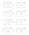
- FIG. 4 shows an example of a communications network from which the observation data collection engine 160 collects observation data. This corresponds to the connection relationship at the physical layer.
- this communications network is a network in which routers 1 to 6 are connected as shown. For example, router 1 and router 2 are directly connected, and are adjacent to each other. Router 1 and router 4 are not directly connected, and are not adjacent to each other.
- the causal model construction engine 110 constructs the causal model shown in FIG. 5 for the communication network (physical layer network) shown in FIG. 4 based on the knowledge of an expert operator, etc.
- the causal model consists of device nodes that represent the state of each device (router) in the communication network, and observation nodes that represent whether a log (e.g., syslog related to link down) has been generated from the device. In other words, the observation nodes represent the observation results of each device.
- the causal model may also be called a Bayesian network.
- Router 1 which is an equipment node
- Routers 1 and 2 which are observation nodes. This indicates that if an abnormality occurs in Router 1, it may affect the observation data of Router 1 and the observation data of Router 2.
- router 2 which is an equipment node
- routers 1, 2, 3, and 6 which are observation nodes. This indicates that if an abnormality occurs in router 2, it may affect the observation data of routers 1, 2, 3, and 6.
- the observation data pre-processing engine 130 takes into consideration the layer of the logs collected by the observation data collection engine 160, selects logs to be used for estimating anomaly locations using a causal model from the collected logs, and stores the selected logs in the observation data DB 140. As described above, only logs at the lowest layer are extracted, and the extracted logs are stored in the observation data DB 140.
- the logs selected by the observation data pre-processing engine 130 are not limited to logs from the lowest layer.
- the observation data pre-processing engine 130 may select logs from multiple layers (e.g., the lowest layer and the second lowest layer).
- the layers increase from “physical” to “logical”, similar to the general concept of layers.
- equipment is a lower layer than “physical”.
- the definition of high/low layers may be set arbitrarily.
- the abnormality location estimation device 100 does not use the physical layer log or the logical layer log, but only uses the equipment layer log to determine the abnormality location.
- the observation data preprocessing engine 130 extracts only the equipment layer log, which is the lowest layer, from the equipment layer log, physical layer log, and logical layer log, and stores it in the observation data DB 140.
- the abnormality location estimation device 100 does not use the logical layer log, but only the physical layer log to determine the abnormality location.
- the observation data preprocessing engine 130 extracts only the physical layer log, which is the lowest layer, from the physical layer log and the logical layer log, and stores it in the observation data DB 140.
- the anomaly location estimation device 100 uses the log in the logical layer to determine the abnormality location.
- the observation data preprocessing engine 130 stores only the log in the logical layer in the observation data DB 140.
- the observation data pre-processing engine 130 holds a table that associates the type of log with the layer, and determines the layer of a new log by referencing this table.
- the observation data preprocessing engine 130 holds a trained model that has learned the relationship between a log and the layer to which the log belongs, and by inputting a log into the model, the layer of the log can be obtained as an output from the model.
- the causal model construction engine 110 constructs a causal model based on the logs to be used. If the logs to be used are device layer logs or physical layer logs, the causal model is constructed based on the physical connection relationships, as in Non-Patent Document 3.
- the method of constructing the causal model in this case is as described with reference to Figures 4 and 5, and in both cases where the log used is an equipment layer log and where the log used is a physical layer log, a causal model such as that shown in Figure 5 is constructed. Note that, here, an example is assumed in which the causal model when the log used is an equipment layer log is the same as the causal model when the log used is a physical layer log, but there are also cases in which they are different.
- the causal model construction engine 110 constructs a causal model based on the connection relationships in the logical layer read from the connection relationship DB 170.
- the above method makes it possible to build a causal model based only on the connection relationships, and to estimate various anomalies, from anomalies in the device layer to anomalies in the logical layer, thereby improving the accuracy of anomaly location estimation.
- Non-Patent Document 3 a causal model is constructed from the connection relationships between devices, so a causal model like the one shown in Figure 5 is created.
- FIG. 6 is a diagram showing an example of the connection relationship in the logical layer of the communication network according to this embodiment. As shown in FIG. 6, unlike the connection relationship in the physical layer (or device layer) shown in FIG. 4, for example, router 1 and router 3 are directly connected. This direct connection is a logical direct connection.
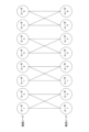
- Figure 7 shows an example of a causal model constructed based on the connection relationships in the logical layer shown in Figure 6.
- router 1 which is an equipment node
- routers 1 and 3 which are observation nodes. This indicates that if an abnormality occurs in router 1, it may affect the observation data of routers 1 and 3.
- the abnormality in this case is an abnormality related to the logical layer log.
- the values of the observation nodes are defined as follows for the constructed causal model.
- an equipment node is denoted by x i
- an observation node is denoted by y i , where i ⁇ (1, . . . N), where N is the number of equipment.
- Each x i takes a value of 0 (normal state) or 1 (abnormal state). It is possible for it to take multiple values, 3 or more, instead of the two values 0 and 1. In that case, the minimum value is the normal state, the maximum value is the abnormal state, and the value c between them is defined as a value that indicates abnormality at the rate of "c/(maximum value - minimum value)".
- Each yi takes a value of 0 or 1, and indicates that a log has occurred at the i-th router.
- the log used here is only the log of the original layer (the log of the lowest layer). It is also possible to take multiple values, 3 or more, instead of the two values 0 and 1, in which case the value is defined as the number of logs that have occurred at the i-th router.
- the inference itself using the causal model is the same as the method in Non-Patent Document 3, and inference is performed by defining the prior probability P(x i ) and the conditional probability P(y j
- the observation data preprocessing engine 130 determines the layer to which the collected logs belong and extracts only the logs from the lowest layer, thereby improving the accuracy of estimating abnormal locations within the communication network.
- Additional Notes Memory, at least one processor coupled to the memory; Including, The processor, Collect logs from communication networks, a layer to which each of the collected logs belongs is determined, and a log to be used for estimating a failure location using a causal model is selected based on the layer.
- the log processing device includes, the processor, selects only a log of a lowest layer among the determined one or more layers as a log to be used for estimating a failure location using a causal model.
- Additional Note 3 The log processing device according to claim 1 or 2, wherein the processor constructs a causal model based on a connection relationship between nodes in a layer to which the selected log belongs.
- a log processing method executed by a log processing device comprising: A log collection step of collecting logs from a communication network; a log selection step of determining a layer to which each log collected by the log collection step belongs, and selecting a log to be used for estimating a failure location using a causal model based on the layer.
- a non-transitory storage medium storing a program for causing a computer to function as each unit in the log processing device according to any one of claims 1 to 4.
- Anomaly location estimation device 110 Causal model construction engine 120 Causal model inference engine 130 Observation data pre-processing engine 140 Observation data DB 150 Output interface 160 Observation data collection engine 170 Connection relationship DB 200 Log collection device 210 Log collection unit 220 Log selection unit 220 1000 Drive device 1001 Recording medium 1002 Auxiliary storage device 1003 Memory device 1004 CPU 1005 Interface device 1006 Display device 1007 Input device 1008 Output device
Landscapes
- Engineering & Computer Science (AREA)
- Artificial Intelligence (AREA)
- Computer Vision & Pattern Recognition (AREA)
- Databases & Information Systems (AREA)
- Evolutionary Computation (AREA)
- Medical Informatics (AREA)
- Software Systems (AREA)
- Computer Networks & Wireless Communication (AREA)
- Signal Processing (AREA)
- Data Exchanges In Wide-Area Networks (AREA)
Abstract
ログ処理装置において、通信ネットワークからログを収集するログ収集部と、前記ログ収集部により収集された各ログが属するレイヤを判定し、前記レイヤに基づいて、因果モデルを用いた障害箇所推定のために使用するログを選択するログ選択部とを備える。
Description
本発明は、通信ネットワークから収集したログに基づいて、通信ネットワークの異常箇所を推定する技術に関連するものである。
通信事業者にとって、通信ネットワーク内に発生する異常に対して、異常の状態の把握や迅速な対応は重要である。こうした中で、通信ネットワーク内の異常を早期に検知するための研究や、異常箇所の推定を行う研究が行われている(非特許文献1、2)。
異常箇所を推定する手法として、ベイジアンネットワークを用いて、異常箇所とそれによって引き起こされる通信ネットワーク内のデータ(観測データと呼ぶ)の変化の関係性をモデル化(因果モデルと呼ぶ)し、異常時の観測データから異常箇所を推定する手法が提案されている(非特許文献3)。
例えば、ルータ間で通信ができなくなると対向ルータと通信できなくなったことを表すログが生成されるため、非特許文献3では、ルータの異常は、異常状態になったルータと物理的に隣接しているルータの観測データのみに影響があるという仮定をもとに、通信ネットワーク内の機器に対して、各機器の状態を表す機器ノードと、その機器からリンクダウンに関するログが発生したかどうかを表す観測ノードからなる因果モデルを構築し、異常箇所の判定を行っている。
また、非特許文献4では、通信ネットワーク内の様々な異常に対して、異常箇所推定を行えるように、物理的な対向装置のリンクダウン以外にも様々なログを用いている。例えば、ルータなどの機器からは、CPUやメモリ、インタフェースモジュールなどの機器の状態(機器レイヤと呼ぶ)を表すログ、物理的に接続している対向装置とのインタフェースの接続などの状態(物理レイヤと呼ぶ)を表すログ、及び、論理的に接続している機器の状態(論理レイヤと呼ぶ)を表すログなど、異常になったレイヤごとに異なったログが出力される。これらを用いて、異常パターン、あるいは生成されるログの原因となりえる事象ごとにオペレーターの知識を用いて因果モデルを作成し、異常箇所の推定を行う。
K. Tajiri, T. Iwata, Y. Matsuo and K. Watanabe, "Fault Detection of ICT systems with Deep Learning Model for Missing Data," 2021 IFIP/IEEE International Symposium on Integrated Network Management (IM), 2021, pp. 445-451.
Y. Matsuo, Y. Nakano, A. Watanabe, K. Watanabe, K. Ishibashi, and K. Kawahara, "Root-cause diagnosis for rare failures using Bayesian network with dynamic modification," Proc. IEEE, ICC, 2018.
Srikanth Kandula, Dina Katabi, and Jean-philippe Vasseur. Shrink: A tool for failure diagnosis in IP networks. Proceedings of the 2005 ACM SIGCOMM workshop on Mining network data, pages 173-178, 2005.
He Yan, Lee Breslau, Zihui Ge, Dan Massey, Dan Pei, and Jennifer Yates, " G-RCA: A Generic Root Cause Analysis Platform for Service Quality Management in Large IP Networks", IEEE/ACM TRANSACTIONS ON NETWORKING, VOL. 20, NO. 6, DECEMBER 2012
非特許文献4に開示された技術では、使用するログの種類が増えるため、非特許文献3に開示された技術で発見できる異常箇所よりも多くの異常に対して異常箇所の推定が行える。しかし、事前に異常パターン、あるいは生成されるログの原因となりえる事象ごとにオペレーターの知識を用いて因果モデルを作成する必要があるという課題がある。
また、非特許文献3に開示された技術では、ルータの異常は、異常状態になったルータと物理的に隣接しているルータの観測データのみに影響があるという仮定をもとに因果モデルを作成しているため、接続関係の情報があれば因果モデルを構築できる。
しかし、非特許文献3において、使用するログが物理レイヤのリンクダウンに関するログである。そのため、物理レイヤの故障において、故障により疎通ができなくなるため、故障が発生したルータとその隣接しているルータの両方のルータからリンクダウンのログが生成される、あるいは、論理レイヤの故障において、物理的には対向ではないが論理的に接続している機器からリンクダウンのログが出る。従って、異常箇所が推定できない場合があるという課題がある。
例えば、ルータ内のパケットを処理するチップが故障した場合、他のルータと疎通不可になるので、故障が発生した機器、故障した機器と物理的に接続している機器、故障した機器と論理的に接続している機器など、様々な機器からリンクダウンのログが出る。そのため、結果として異常箇所の推定精度が下がるという課題がある。
本発明は上記の点に鑑みてなされたものであり、通信ネットワーク内の異常箇所の推定精度を向上させるための技術を提供することを目的とする。
開示の技術によれば、通信ネットワークからログを収集するログ収集部と、
前記ログ収集部により収集された各ログが属するレイヤを判定し、前記レイヤに基づいて、因果モデルを用いた障害箇所推定のために使用するログを選択するログ選択部と
を備えるログ処理装置が提供される。
前記ログ収集部により収集された各ログが属するレイヤを判定し、前記レイヤに基づいて、因果モデルを用いた障害箇所推定のために使用するログを選択するログ選択部と
を備えるログ処理装置が提供される。
開示の技術によれば、通信ネットワーク内の異常箇所の推定精度を向上させるための技術が提供される。
以下、図面を参照して本発明の実施の形態(本実施の形態)を説明する。以下で説明する実施の形態は一例に過ぎず、本発明が適用される実施の形態は、以下の実施の形態に限られるわけではない。
本実施の形態では、後述する異常箇所推定装置100が、収集するログのレイヤを考慮して、因果モデルの構築と観測ノードを定義することで、機器の接続関係のみから因果モデルを構築し、かつ、様々な異常に対して異常箇所の推定を行うことができる。以下、課題を解決するための装置構成、及び装置動作を詳細に説明する。
(装置構成例)
図1に、本実施の形態における異常箇所推定装置100の構成例を示す。図1に示すように、異常箇所推定装置100は、観測データ収集エンジン160、観測データDB140、観測データ前処理エンジン130、接続関係DB170、因果モデル構築エンジン110、因果モデル推論エンジン120、利用者への出力インタフェース150を有する。
図1に、本実施の形態における異常箇所推定装置100の構成例を示す。図1に示すように、異常箇所推定装置100は、観測データ収集エンジン160、観測データDB140、観測データ前処理エンジン130、接続関係DB170、因果モデル構築エンジン110、因果モデル推論エンジン120、利用者への出力インタフェース150を有する。
なお、観測データ収集エンジン160、観測データ前処理エンジン130、因果モデル構築エンジン110、因果モデル推論エンジン120をそれぞれ、観測データ収集部160、観測データ前処理部130、因果モデル構築部110、因果モデル推論部120と呼んでもよい。また、観測データ収集エンジン160、観測データ前処理エンジン130、因果モデル構築エンジン110、因果モデル推論エンジン120をそれぞれ、観測データ収集回路160、観測データ前処理回路130、因果モデル構築回路110、因果モデル推論回路120と呼んでもよい。
また、異常箇所推定装置100をログ処理装置と呼んでもよい。また、観測データ収集エンジン160、観測データ前処理エンジン130をそれぞれ、ログ収集部、ログ選択部と呼んでもよい。異常箇所推定装置100の動作概要は下記のとおりである。
観測データ収集エンジン160は、通信ネットワークから観測データ(機器から発生するログ等)を収集する。観測データ前処理エンジン130は、観測データ収集エンジン160により収集されたログが属するレイヤを判定し、最も低レイヤのログのみを抽出し、抽出したログを観測データDB140に格納する。
因果モデル構築エンジン110は、観測データDB140に格納されたログが属するレイヤに応じて、接続関係DB170に保存されている物理的あるいは論理的なノードの接続関係を入力とし、因果モデルを構築する。因果モデル推論エンジン120は観測データDB140へ格納されたログの発生状況をもとに、観測ノードの値を決定し、異常箇所の推定を実施し、出力インタフェース150に推定結果である異常箇所を出力する。
出力インタフェース150は、利用者に対して通信ネットワークの中の異常発生箇所とその際の最大事後確率等を表示する。また、出力インタフェース150は、運用システムに新たにマシンが追加された際などは、因果グラフへのノードの追加を行い、また、それに伴う因果関係の変化を利用者に修正させることもできる。
なお、異常箇所推定装置100は、1つの装置(コンピュータ)であってもよいし、複数の装置からなるものであってもよい。
また、観測データ収集エンジン160と観測データ前処理エンジン130により1つの装置を構成し、それをログ処理装置と呼んでよい。
図2にログ処理装置200の構成例を示す。図2に示すように、ログ収集装置200は、ログ収集部210、及びログ選択部220を含む。ログ収集部210とログ選択部220はそれぞれ観測データ収集エンジン160と観測データ前処理エンジン130に対応する。ログ収集装置200は、因果モデル構築エンジン110等を更に含んでもよい。
ログ収集部210は、通信ネットワークからログを収集する。ログ選択部220は、ログ収集部210により収集された各ログが属するレイヤを判定し、当該レイヤに基づいて、因果モデルを用いた障害箇所推定のために使用するログを選択する。例えば、ログ選択部220は、判定された1つ以上のレイヤのうち、最も低いレイヤのログのみを、因果モデルを用いた障害箇所推定のために使用するログとして選択する。
(ハードウェア構成例)
本明細書に記載したいずれの装置(異常箇所推定装置100、ログ処理装置200)も、例えば、コンピュータにプログラムを実行させることにより実現できる。このコンピュータは、物理的なコンピュータであってもよいし、クラウド上の仮想マシンであってもよい。
本明細書に記載したいずれの装置(異常箇所推定装置100、ログ処理装置200)も、例えば、コンピュータにプログラムを実行させることにより実現できる。このコンピュータは、物理的なコンピュータであってもよいし、クラウド上の仮想マシンであってもよい。
すなわち、当該装置は、コンピュータに内蔵されるCPUやメモリ等のハードウェア資源を用いて、当該装置で実施される処理に対応するプログラムを実行することによって実現することが可能である。上記プログラムは、コンピュータが読み取り可能な記録媒体(可搬メモリ等)に記録して、保存したり、配布したりすることが可能である。また、上記プログラムをインターネットや電子メール等、ネットワークを通して提供することも可能である。
図3は、上記コンピュータのハードウェア構成例を示す図である。図3のコンピュータは、それぞれバスBSで相互に接続されているドライブ装置1000、補助記憶装置1002、メモリ装置1003、CPU1004、インタフェース装置1005、表示装置1006、入力装置1007、出力装置1008等を有する。
当該コンピュータでの処理を実現するプログラムは、例えば、CD-ROM又はメモリカード等の記録媒体1001によって提供される。プログラムを記憶した記録媒体1001がドライブ装置1000にセットされると、プログラムが記録媒体1001からドライブ装置1000を介して補助記憶装置1002にインストールされる。但し、プログラムのインストールは必ずしも記録媒体1001より行う必要はなく、ネットワークを介して他のコンピュータよりダウンロードするようにしてもよい。補助記憶装置1002は、インストールされたプログラムを格納すると共に、必要なファイルやデータ等を格納する。
メモリ装置1003は、プログラムの起動指示があった場合に、補助記憶装置1002からプログラムを読み出して格納する。CPU1004は、メモリ装置1003に格納されたプログラムに従って、当該装置に係る機能を実現する。インタフェース装置1005は、ネットワークに接続するためのインタフェースとして用いられる。表示装置1006はプログラムによるGUI(Graphical User Interface)等を表示する。入力装置1007はキーボード及びマウス、ボタン、又はタッチパネル等で構成され、様々な操作指示を入力させるために用いられる。出力装置1008は演算結果を出力する。
(動作例)
以下では、異常箇所推定装置100の動作を、より詳細に説明する。なお、本実施の形態では、ルータにより構成される通信ネットワークを対象とすることを想定しているが、これは一例である。本発明に係る技術は、通信ネットワークを構成するノードの種類に依らずに適用可能である。
以下では、異常箇所推定装置100の動作を、より詳細に説明する。なお、本実施の形態では、ルータにより構成される通信ネットワークを対象とすることを想定しているが、これは一例である。本発明に係る技術は、通信ネットワークを構成するノードの種類に依らずに適用可能である。
<因果モデルについて>
本発明に係る技術に係る前処理について説明する前に、まず、非特許文献3に基づく、因果モデルの構築について説明する。
本発明に係る技術に係る前処理について説明する前に、まず、非特許文献3に基づく、因果モデルの構築について説明する。
図4に、観測データ収集エンジン160が観測データを収集する対象となる通信ネットワークの例を示す。これは、物理レイヤの接続関係に相当する。図4に示すように、この通信ネットワークは、ルータ1~6が図示するとおりに接続されたネットワークである。例えば、ルータ1とルータ2は直接に接続されたおり、これらは互いに隣接関係にある。ルータ1とルータ4は直接には接続されておらず、これらは隣接関係にない。
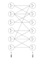
因果モデル構築エンジン110は、エキスパートオペレーターの知識等に基づいて、図4に示す通信ネットワーク(物理レイヤのネットワーク)に対して、図5に示す因果モデルを構築する。因果モデルは、通信ネットワーク内の機器(ルータ)に対して、各機器の状態を表す機器ノードと、その機器からログ(例:リンクダウンに関するsyslog)が発生したかどうかを表す観測ノードからなる。つまり、観測ノードは、各機器の観測結果を表す。なお、因果モデルをベイジアンネットワークと呼んでもよい。
例えば、図5の因果モデルにおいて、機器ノードのルータ1は、観測ノードのルータ1、2と接続されている。これは、ルータ1に異常が発生した場合に、ルータ1の観測データとルータ2の観測データに影響する可能性があるということを示している。
また、例えば、図5の因果モデルにおいて、機器ノードのルータ2は、観測ノードのルータ1、2、3、6と接続されている。これは、ルータ2に異常が発生した場合に、ルータ1、2、3、6のそれぞれの観測データに影響する可能性があるということを示している。
<観測データ前処理エンジン130についての詳細説明>
本実施の形態において、観測データ前処理エンジン130は、観測データ収集エンジン160により収集されたログのレイヤを考慮して、収集されたログの中から、因果モデルを用いた異常箇所推定に使用するログを選択し、選択したログを観測データDB140に格納する。前述のとおり、最も低いレイヤのログのみを抽出し、抽出したログを観測データDB140に格納する。
本実施の形態において、観測データ前処理エンジン130は、観測データ収集エンジン160により収集されたログのレイヤを考慮して、収集されたログの中から、因果モデルを用いた異常箇所推定に使用するログを選択し、選択したログを観測データDB140に格納する。前述のとおり、最も低いレイヤのログのみを抽出し、抽出したログを観測データDB140に格納する。
なお、観測データ前処理エンジン130が選択するログは、最も低いレイヤのログに限定されるわけではない。例えば、観測データ前処理エンジン130は、複数レイヤ(例:最も低いレイヤと2番目に低いレイヤ)のログを選択する場合があってもよい。
また、本実施の形態では、一般的なレイヤの概念と同様に、「物理」から「論理」へ、レイヤが高くなることを想定している。また、本実施の形態では、「機器」のほうが「物理」よりもレイヤが低いこととしている。ただし、レイヤの高/低の定義は任意に定めてよい。観測データ前処理エンジン130の具体的処理内容は下記のとおりである。
通信ネットワーク内の異常において、機器レイヤの異常に関するログが発生した場合、他の機器と疎通ができなくなるため、物理レイヤ、論理レイヤのログも発生するが、機器レイヤのログが大元のログであるため、異常箇所推定装置100は、物理レイヤのログ、論理レイヤのログを使用せず機器レイヤのログだけを使用して、異常箇所を判定する。つまり、観測データ前処理エンジン130は、機器レイヤのログ、物理レイヤのログ、論理レイヤのログのうち、最もレイヤの低い機器レイヤのログのみを抽出し、観測データDB140に格納する。
また、機器レイヤの異常に関するログが発生せずに、物理レイヤの異常に関するログが発生した場合も、他の機器と疎通ができなくなるため論理レイヤのログも出るが、物理レイヤのログが大元のログであるため、異常箇所推定装置100は、論理レイヤのログを使用せず、物理レイヤのログだけを使用し、異常箇所を判定する。つまり、観測データ前処理エンジン130は、物理レイヤのログ、及び論理レイヤのログのうち、最もレイヤの低い物理レイヤのログのみを抽出し、観測データDB140に格納する。
また、機器レイヤの異常に関するログ及び物理レイヤの異常に関するログのいずれも発生せずに、論理レイヤの異常に関するログが発生した場合は、異常箇所推定装置100は、論理レイヤのログを用いて異常箇所を判定する。つまり、観測データ前処理エンジン130は、論理レイヤのログのみを観測データDB140に格納する。
ここで、各ログがどのレイヤに属するかは、オペレーターの知識をもとに一つ一つ決めることとしてもよいし、ログとそのログがどのレイヤに属するかのデータのペアを用意し機械学習モデルなどを用いて学習し、各ログを該当レイヤに分類しても良い。
各ログがどのレイヤに属するかを、オペレーターの知識をもとに一つ一つ決めておく場合においては、例えば、観測データ前処理エンジン130は、ログの種類とレイヤとを対応付けたテーブルを保持し、当該テーブルを参照することで、新たなログのレイヤを判断する。
また、機械学習モデルを使用する場合には、例えば、観測データ前処理エンジン130は、ログとそのログが属するレイヤとの関係を学習した学習済みのモデルを保持し、当該モデルにログを入力することで、当該モデルからの出力として当該ログのレイヤを得ることができる。
<因果モデル構築エンジン110についての詳細説明>
観測データ前処理エンジン130によるログ選択の次に、因果モデル構築エンジン110が、使用するログに基づいて因果モデルを構築する。使用するログが機器レイヤのログ、又は、物理レイヤのログである場合は非特許文献3と同様に、物理的な接続関係をもとに因果モデルを構築する。
観測データ前処理エンジン130によるログ選択の次に、因果モデル構築エンジン110が、使用するログに基づいて因果モデルを構築する。使用するログが機器レイヤのログ、又は、物理レイヤのログである場合は非特許文献3と同様に、物理的な接続関係をもとに因果モデルを構築する。
この場合の因果モデル構築方法は、図4、図5を参照して説明したとおりであり、使用するログが機器レイヤのログである場合、及び、物理レイヤのログである場合のいずれの場合にも、例えば図5に示すような因果モデルが構築される。なお、ここでは、使用するログが機器レイヤのログである場合の因果モデルと、使用するログが物理レイヤのログである場合の因果モデルとが同じである例を想定しているが、これらが異なる場合もある。
使用するログが論理レイヤのログである場合には、因果モデル構築エンジン110は、接続関係DB170から読み出した、論理レイヤにおける接続関係をもとに、因果モデルを構築する。
上記の方法により、接続関係のみから因果モデルを構築することができ、かつ機器レイヤの異常から論理レイヤの異常まで、様々な異常箇所を推定できるので、異常箇所推定の精度向上が可能となる。
非特許文献3に開示された技術では、機器の接続関係から因果モデルを構築するため、図5に示すような因果モデルが作成される。
一方、本実施の形態においては、物理レイヤの接続関係を用いて因果モデルを構築する場合には、前述のとおり、非特許文献3での因果モデルと同様となるが、論理レイヤの接続関係(論理的な接続関係)を用いて因果モデルを構築する場合には、当該因果モデルは、非特許文献3に開示されたものと異なったものとなる。
図6は、本実施の形態に係る通信ネットワークの論理レイヤにおける接続関係の例を示す図である。図6に示すとおり、図4に示した物理レイヤ(あるいは機器レイヤ)の接続関係とは異なり、例えば、ルータ1とルータ3は直接に接続されている。この直接接続は、論理的な直接接続である。
図7は、図6に示す論理レイヤにおける接続関係に基づいて構築された因果モデルの例を示す。例えば、図7の因果モデルにおいて、機器ノードのルータ1は、観測ノードのルータ1、3と接続されている。これは、ルータ1に異常が発生した場合に、ルータ1、3のそれぞれの観測データに影響する可能性があるということを示している。なお、この場合の異常は、論理レイヤのログに関連する異常である。
<因果モデル推論エンジン120についての詳細説明>
本実施の形態では、構築した因果モデルに対して、以下のように観測ノードの値を定義する。
本実施の形態では、構築した因果モデルに対して、以下のように観測ノードの値を定義する。
異常箇所推定の対象となるシステム(通信ネットワーク)の因果モデルにおける機器ノードをxi、観測ノードをyi,i∈(1,…N)とする。Nは機器数である。
各xiは0(正常状態)か1(異常状態)の値を取るとする。なお、0か1の2値ではなく、3値以上の多値を取ることも可能であり、その場合は最小値が正常状態、最大値が異常状態、その間の値cは、「c/(最大値-最小値)」の割合で異常となっていることを意味する値、などのように定義する。
各yiは0か1の値を取るとし、i番目のルータでログが発生したことを表す。既に説明したとおり、ここで使用するログは、大元になったレイヤのログ(最も低いレイヤのログ)だけとする。なお、0か1の2値ではなく、3値以上の多値を取ることも可能であり、その場合はi番目のルータで発生したログの発生件数を値とするなどのように定義する。
上記の因果モデルへの入力値については、因果モデル推論エンジン120が、観測データDB140から読み出したログから決定(計算)することができる。
因果モデルを用いた推論自体は非特許文献3での手法と同じであり、事前確率P(xi)と条件付き確率P(yj|xi)を規定し、推論を行う。
(実施の形態に係る技術の効果について)
上述したとおり、観測データ前処理エンジン130が、収集されたログが属するレイヤを判定し、最も低いレイヤのログのみを抽出することとしたので、通信ネットワーク内の異常箇所の推定精度を向上させことができる。
上述したとおり、観測データ前処理エンジン130が、収集されたログが属するレイヤを判定し、最も低いレイヤのログのみを抽出することとしたので、通信ネットワーク内の異常箇所の推定精度を向上させことができる。
以上の実施形態に関し、更に以下の付記を開示する。
<付記>
(付記項1)
メモリと、
前記メモリに接続された少なくとも1つのプロセッサと、
を含み、
前記プロセッサは、
通信ネットワークからログを収集し、
前記収集された各ログが属するレイヤを判定し、前記レイヤに基づいて、因果モデルを用いた障害箇所推定のために使用するログを選択する
ログ処理装置。
(付記項2)
前記プロセッサは、判定された1つ以上のレイヤのうち、最も低いレイヤのログのみを、因果モデルを用いた障害箇所推定のために使用するログとして選択する
付記項1に記載のログ処理装置。
(付記項3)
前記プロセッサは、選択されたログが属するレイヤにおけるノード間の接続関係に基づいて、因果モデルを構築する
付記項1又は2に記載のログ処理装置。
(付記項4)
前記プロセッサは、ログとレイヤとの関係を学習済みのモデルを用いて各ログが属するレイヤを判定する
付記項1ないし3のうちいずれか1項に記載のログ処理装置。
(付記項5)
ログ処理装置が実行するログ処理方法であって、
通信ネットワークからログを収集するログ収集ステップと、
前記ログ収集ステップにより収集された各ログが属するレイヤを判定し、前記レイヤに基づいて、因果モデルを用いた障害箇所推定のために使用するログを選択するログ選択ステップと
を備えるログ処理方法。
(付記項6)
コンピュータを、付記項1ないし4のうちいずれか1項に記載のログ処理装置における各部として機能させるためのプログラムを記憶した非一時的記憶媒体。
以上、本実施の形態について説明したが、本発明はかかる特定の実施形態に限定されるものではなく、特許請求の範囲に記載された本発明の要旨の範囲内において、種々の変形・変更が可能である。
100 異常箇所推定装置
110 因果モデル構築エンジン
120 因果モデル推論エンジン
130 観測データ前処理エンジン
140 観測データDB
150 出力インタフェース
160 観測データ収集エンジン
170 接続関係DB
200 ログ収集装置
210 ログ収集部
220 ログ選択部220
1000 ドライブ装置
1001 記録媒体
1002 補助記憶装置
1003 メモリ装置
1004 CPU
1005 インタフェース装置
1006 表示装置
1007 入力装置
1008 出力装置
110 因果モデル構築エンジン
120 因果モデル推論エンジン
130 観測データ前処理エンジン
140 観測データDB
150 出力インタフェース
160 観測データ収集エンジン
170 接続関係DB
200 ログ収集装置
210 ログ収集部
220 ログ選択部220
1000 ドライブ装置
1001 記録媒体
1002 補助記憶装置
1003 メモリ装置
1004 CPU
1005 インタフェース装置
1006 表示装置
1007 入力装置
1008 出力装置
Claims (6)
- 通信ネットワークからログを収集するログ収集部と、
前記ログ収集部により収集された各ログが属するレイヤを判定し、前記レイヤに基づいて、因果モデルを用いた障害箇所推定のために使用するログを選択するログ選択部と
を備えるログ処理装置。 - 前記ログ選択部は、判定された1つ以上のレイヤのうち、最も低いレイヤのログのみを、因果モデルを用いた障害箇所推定のために使用するログとして選択する
請求項1に記載のログ処理装置。 - 前記ログ選択部により選択されたログが属するレイヤにおけるノード間の接続関係に基づいて、因果モデルを構築する因果モデル構築部
を更に備える請求項1に記載のログ処理装置。 - 前記ログ選択部は、ログとレイヤとの関係を学習済みのモデルを用いて各ログが属するレイヤを判定する
請求項1に記載のログ処理装置。 - ログ処理装置が実行するログ処理方法であって、
通信ネットワークからログを収集するログ収集ステップと、
前記ログ収集ステップにより収集された各ログが属するレイヤを判定し、前記レイヤに基づいて、因果モデルを用いた障害箇所推定のために使用するログを選択するログ選択ステップと
を備えるログ処理方法。 - コンピュータを、請求項1ないし4のうちいずれか1項に記載のログ処理装置における各部として機能させるためのプログラム。
Priority Applications (2)
| Application Number | Priority Date | Filing Date | Title |
|---|---|---|---|
| PCT/JP2023/020845 WO2024252479A1 (ja) | 2023-06-05 | 2023-06-05 | ログ処理装置、ログ処理方法、及びプログラム |
| JP2025525455A JPWO2024252479A1 (ja) | 2023-06-05 | 2023-06-05 |
Applications Claiming Priority (1)
| Application Number | Priority Date | Filing Date | Title |
|---|---|---|---|
| PCT/JP2023/020845 WO2024252479A1 (ja) | 2023-06-05 | 2023-06-05 | ログ処理装置、ログ処理方法、及びプログラム |
Publications (1)
| Publication Number | Publication Date |
|---|---|
| WO2024252479A1 true WO2024252479A1 (ja) | 2024-12-12 |
Family
ID=93795190
Family Applications (1)
| Application Number | Title | Priority Date | Filing Date |
|---|---|---|---|
| PCT/JP2023/020845 Ceased WO2024252479A1 (ja) | 2023-06-05 | 2023-06-05 | ログ処理装置、ログ処理方法、及びプログラム |
Country Status (2)
| Country | Link |
|---|---|
| JP (1) | JPWO2024252479A1 (ja) |
| WO (1) | WO2024252479A1 (ja) |
Citations (3)
| Publication number | Priority date | Publication date | Assignee | Title |
|---|---|---|---|---|
| JP2002354038A (ja) * | 2001-05-23 | 2002-12-06 | Fujitsu Ltd | レイヤ型ネットワークの管理システム |
| US20190165988A1 (en) * | 2017-11-27 | 2019-05-30 | Google Llc | Real-time probabilistic root cause correlation of network failures |
| WO2021079521A1 (ja) * | 2019-10-25 | 2021-04-29 | 日本電信電話株式会社 | ルール生成装置、方法及びプログラム |
-
2023
- 2023-06-05 JP JP2025525455A patent/JPWO2024252479A1/ja active Pending
- 2023-06-05 WO PCT/JP2023/020845 patent/WO2024252479A1/ja not_active Ceased
Patent Citations (3)
| Publication number | Priority date | Publication date | Assignee | Title |
|---|---|---|---|---|
| JP2002354038A (ja) * | 2001-05-23 | 2002-12-06 | Fujitsu Ltd | レイヤ型ネットワークの管理システム |
| US20190165988A1 (en) * | 2017-11-27 | 2019-05-30 | Google Llc | Real-time probabilistic root cause correlation of network failures |
| WO2021079521A1 (ja) * | 2019-10-25 | 2021-04-29 | 日本電信電話株式会社 | ルール生成装置、方法及びプログラム |
Also Published As
| Publication number | Publication date |
|---|---|
| JPWO2024252479A1 (ja) | 2024-12-12 |
Similar Documents
| Publication | Publication Date | Title |
|---|---|---|
| US11818014B2 (en) | Multi-baseline unsupervised security-incident and network behavioral anomaly detection in cloud-based compute environments | |
| CN1665205B (zh) | 故障检测和诊断 | |
| US7631222B2 (en) | Method and apparatus for correlating events in a network | |
| US7113988B2 (en) | Proactive on-line diagnostics in a manageable network | |
| US9025434B2 (en) | Automated datacenter network failure mitigation | |
| US8583779B2 (en) | Root cause analysis approach with candidate elimination using network virtualization | |
| EP3338191B1 (en) | Diagnostic framework in computing systems | |
| US8423826B2 (en) | Method, apparatus and system for displaying result of failure root cause analysis | |
| US10728085B1 (en) | Model-based network management | |
| CN113973042B (zh) | 用于网络问题的根本原因分析的方法和系统 | |
| CN118119926A (zh) | 基于候选运行手册的结果与事件的补救的相关性推荐候选运行手册 | |
| US20090063902A1 (en) | Preliminary Classification of Events to Facilitate Cause-Based Analysis | |
| WO2021002298A1 (ja) | 故障影響推定装置、故障影響推定方法、及びプログラム | |
| CN116418653A (zh) | 基于多指标根因定位算法的故障定位方法及装置 | |
| WO2020214408A1 (en) | Timeout mode for storage devices | |
| JP7414135B2 (ja) | モデル構築装置、推定装置、モデル構築方法、推定方法及びプログラム | |
| US7844443B2 (en) | Network subscriber experience modeling | |
| JP2018124829A (ja) | 状態判定装置、状態判定方法及びプログラム | |
| Matsuo et al. | Root-cause diagnosis for rare failures using bayesian network with dynamic modification | |
| WO2024252479A1 (ja) | ログ処理装置、ログ処理方法、及びプログラム | |
| WO2025041236A1 (ja) | ログ処理装置、ログ処理方法、及びプログラム | |
| CN117336228A (zh) | 一种基于机器学习的igp仿真推荐方法、装置及介质 | |
| JP7720005B2 (ja) | 異常箇所推定装置、異常箇所推定方法、及びプログラム | |
| Schoenfisch et al. | Root cause analysis through abduction in markov logic networks | |
| US7558770B2 (en) | Method and system to detect application non-conformance |
Legal Events
| Date | Code | Title | Description |
|---|---|---|---|
| 121 | Ep: the epo has been informed by wipo that ep was designated in this application |
Ref document number: 23940586 Country of ref document: EP Kind code of ref document: A1 |
|
| ENP | Entry into the national phase |
Ref document number: 2025525455 Country of ref document: JP Kind code of ref document: A |
|
| WWE | Wipo information: entry into national phase |
Ref document number: 2025525455 Country of ref document: JP |
|
| NENP | Non-entry into the national phase |
Ref country code: DE |