WO2024252483A1 - Dispositif à cycle de réfrigération - Google Patents
Dispositif à cycle de réfrigération Download PDFInfo
- Publication number
- WO2024252483A1 WO2024252483A1 PCT/JP2023/020849 JP2023020849W WO2024252483A1 WO 2024252483 A1 WO2024252483 A1 WO 2024252483A1 JP 2023020849 W JP2023020849 W JP 2023020849W WO 2024252483 A1 WO2024252483 A1 WO 2024252483A1
- Authority
- WO
- WIPO (PCT)
- Prior art keywords
- heat medium
- heat
- heat exchanger
- flow path
- refrigerant
- Prior art date
- Legal status (The legal status is an assumption and is not a legal conclusion. Google has not performed a legal analysis and makes no representation as to the accuracy of the status listed.)
- Ceased
Links
Images






Classifications
-
- F—MECHANICAL ENGINEERING; LIGHTING; HEATING; WEAPONS; BLASTING
- F25—REFRIGERATION OR COOLING; COMBINED HEATING AND REFRIGERATION SYSTEMS; HEAT PUMP SYSTEMS; MANUFACTURE OR STORAGE OF ICE; LIQUEFACTION SOLIDIFICATION OF GASES
- F25B—REFRIGERATION MACHINES, PLANTS OR SYSTEMS; COMBINED HEATING AND REFRIGERATION SYSTEMS; HEAT PUMP SYSTEMS
- F25B13/00—Compression machines, plants or systems, with reversible cycle
-
- F—MECHANICAL ENGINEERING; LIGHTING; HEATING; WEAPONS; BLASTING
- F25—REFRIGERATION OR COOLING; COMBINED HEATING AND REFRIGERATION SYSTEMS; HEAT PUMP SYSTEMS; MANUFACTURE OR STORAGE OF ICE; LIQUEFACTION SOLIDIFICATION OF GASES
- F25B—REFRIGERATION MACHINES, PLANTS OR SYSTEMS; COMBINED HEATING AND REFRIGERATION SYSTEMS; HEAT PUMP SYSTEMS
- F25B41/00—Fluid-circulation arrangements
- F25B41/20—Disposition of valves, e.g. of on-off valves or flow control valves
-
- F—MECHANICAL ENGINEERING; LIGHTING; HEATING; WEAPONS; BLASTING
- F25—REFRIGERATION OR COOLING; COMBINED HEATING AND REFRIGERATION SYSTEMS; HEAT PUMP SYSTEMS; MANUFACTURE OR STORAGE OF ICE; LIQUEFACTION SOLIDIFICATION OF GASES
- F25B—REFRIGERATION MACHINES, PLANTS OR SYSTEMS; COMBINED HEATING AND REFRIGERATION SYSTEMS; HEAT PUMP SYSTEMS
- F25B2313/00—Compression machines, plants or systems with reversible cycle not otherwise provided for
- F25B2313/003—Indoor unit with water as a heat sink or heat source
-
- F—MECHANICAL ENGINEERING; LIGHTING; HEATING; WEAPONS; BLASTING
- F25—REFRIGERATION OR COOLING; COMBINED HEATING AND REFRIGERATION SYSTEMS; HEAT PUMP SYSTEMS; MANUFACTURE OR STORAGE OF ICE; LIQUEFACTION SOLIDIFICATION OF GASES
- F25B—REFRIGERATION MACHINES, PLANTS OR SYSTEMS; COMBINED HEATING AND REFRIGERATION SYSTEMS; HEAT PUMP SYSTEMS
- F25B2313/00—Compression machines, plants or systems with reversible cycle not otherwise provided for
- F25B2313/023—Compression machines, plants or systems with reversible cycle not otherwise provided for using multiple indoor units
- F25B2313/0231—Compression machines, plants or systems with reversible cycle not otherwise provided for using multiple indoor units with simultaneous cooling and heating
-
- F—MECHANICAL ENGINEERING; LIGHTING; HEATING; WEAPONS; BLASTING
- F25—REFRIGERATION OR COOLING; COMBINED HEATING AND REFRIGERATION SYSTEMS; HEAT PUMP SYSTEMS; MANUFACTURE OR STORAGE OF ICE; LIQUEFACTION SOLIDIFICATION OF GASES
- F25B—REFRIGERATION MACHINES, PLANTS OR SYSTEMS; COMBINED HEATING AND REFRIGERATION SYSTEMS; HEAT PUMP SYSTEMS
- F25B2313/00—Compression machines, plants or systems with reversible cycle not otherwise provided for
- F25B2313/027—Compression machines, plants or systems with reversible cycle not otherwise provided for characterised by the reversing means
- F25B2313/02732—Compression machines, plants or systems with reversible cycle not otherwise provided for characterised by the reversing means using two three-way valves
Definitions
- This disclosure relates to a refrigeration cycle device.
- a refrigeration cycle device equipped with a chiller-type heat source unit is known.
- a refrigerant circulating in a refrigerant circuit is heat-exchanged with a heat medium different from the refrigerant in a heat medium heat exchanger, and the heat medium that has exchanged heat with the refrigerant in the heat medium heat exchanger is supplied to the outside of the heat source unit.
- a refrigeration cycle device equipped with a chiller-type heat source unit is equipped with a heat medium circuit in which the heat medium supplied from the heat source unit circulates.
- a refrigeration cycle device equipped with a chiller-type heat source unit that is equipped with multiple load-side heat exchangers in the heat medium circuit has also been proposed.
- Patent Document 1 discloses an example in which a refrigeration cycle device equipped with a chiller-type heat source unit and multiple load-side heat exchangers is used as an air conditioning device. That is, the refrigeration cycle device described in Patent Document 1 uses multiple load-side heat exchangers as indoor heat exchangers.
- the heat medium circuit is configured as follows. Specifically, the heat medium circuit is equipped with a main pipe through which the heat medium flowing out of the heat source unit flows and which returns the heat medium to the heat source unit. Each of the load-side heat exchangers is connected to the main pipe via a branch pipe. The flow state of the heat medium in each of the load-side heat exchangers is switched by a switching mechanism provided in the branch pipe connected to each of the load-side heat exchangers. In other words, whether or not to flow the heat medium to each of the load-side heat exchangers is switched by a switching mechanism provided in the branch pipe connected to each of the load-side heat exchangers.
- the main pipe of the heat medium circuit is installed so as to pass around each of the load-side heat exchangers.
- Each of the load-side heat exchangers is connected to a main pipe portion located near the load-side heat exchanger by a branch pipe.
- a long main pipe is required in a conventional refrigeration cycle device equipped with a chiller-type heat source unit and multiple load-side heat exchangers.
- the heat medium that has flowed through each of the load-side heat exchangers joins and flows in the main pipe. For this reason, the main pipe needs to be thick in order to suppress the pressure loss that occurs when the heat medium flows through the main pipe.
- a long and thick main pipe needs to be installed on-site in a conventional refrigeration cycle device equipped with a chiller-type heat source unit and multiple load-side heat exchangers.
- a problem with a conventional refrigeration cycle device equipped with a chiller-type heat source unit and multiple load-side heat exchangers is that it takes a long time to install on-site.
- the present disclosure has been made to solve the above-mentioned problems, and aims to provide a refrigeration cycle device equipped with a chiller-type heat source unit and multiple load-side heat exchangers that can reduce on-site installation time compared to conventional methods.
- the refrigeration cycle device has a heat medium heat exchanger in which a refrigerant circulating in a refrigerant circuit exchanges heat with a heat medium different from the refrigerant, and is equipped with a heat source unit that supplies the heat medium that has exchanged heat with the refrigerant in the heat medium heat exchanger to the outside, and is equipped with a heat medium circuit in which the heat medium supplied from the heat source unit circulates, and the heat medium circuit is equipped with a plurality of load side heat exchangers and a switching mechanism that switches the flow state of the heat medium in each of the load side heat exchangers, and the refrigeration cycle device is equipped with a relay unit in which the switching mechanism is housed.
- the piping equivalent to the main pipe of a conventional refrigeration cycle device that is to be installed on-site is the piping that connects the heat source unit and the relay unit. Therefore, in the refrigeration cycle device according to the present disclosure, the piping equivalent to the conventional main pipe that is to be installed on-site is shorter than the conventional main pipe. Therefore, the refrigeration cycle device according to the present disclosure can reduce the installation time on-site compared to conventional devices.
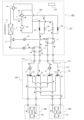
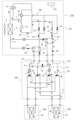
- FIG. 1 is a diagram showing an example of a circuit configuration of a refrigeration cycle device according to a first embodiment in a cooling only operation mode.
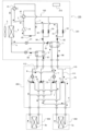
- 4 is a diagram showing the flows of a refrigerant and a heat medium in a cooling-dominated operation mode of the refrigeration cycle apparatus according to the first embodiment.
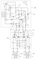
- FIG. 4 is a diagram showing the flows of a refrigerant and a heat medium in a full heating operation mode of the refrigeration cycle apparatus according to the first embodiment.
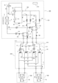
- FIG. 4 is a diagram showing the flows of a refrigerant and a heat medium in a heating-dominated operation mode of the refrigeration cycle apparatus according to the first embodiment.
- FIG. FIG. 11 is a diagram showing an example of a circuit configuration of a refrigeration cycle device according to a second embodiment.
- FIG. 11 is a diagram showing an example of a circuit configuration of a refrigeration cycle device according to a second embodiment.
- FIG. 11 is a diagram showing an example of a circuit configuration of a refrigeration cycle device according to a third embodiment.
- FIG. 11 is a diagram showing an example of a circuit configuration of a refrigeration cycle device according to a third embodiment.
- FIG. 13 is a diagram showing an example of a circuit configuration of a refrigeration cycle device according to a fourth embodiment.
- FIG. 13 is a diagram showing an example of a circuit configuration of a refrigeration cycle device according to a fourth embodiment.
- FIG. 13 is a diagram showing an example of a circuit configuration of a refrigeration cycle device according to a fifth embodiment.
- Fig. 1 is a diagram showing an example of a circuit configuration of a refrigeration cycle device according to embodiment 1 in a full cooling operation mode.
- solid arrows with black tips shown in Fig. 1 and Fig. 2 and subsequent figures indicate the flow direction of a refrigerant.
- dashed arrows with black tips shown in Fig. 1 and Fig. 2 and subsequent figures indicate the flow direction of a heat medium.
- the refrigeration cycle apparatus 200 when showing the open/closed state of an on-off valve or the like, an open flow path is shown in white, and a closed flow path is shown in black.
- the refrigeration cycle apparatus 200 includes a chiller-type heat source unit 201 and a heat medium circuit 110 through which the heat medium supplied from the heat source unit 201 circulates.
- the heat source unit 201 includes a refrigerant circuit 100 in which a refrigerant circulates, and a heat medium heat exchanger.
- the refrigerant circuit 100 and the heat medium heat exchanger are housed in the heat source unit 201.
- the heat medium heat exchanger functions as a condenser or evaporator in the refrigerant circuit 100, and exchanges heat between the refrigerant circulating in the refrigerant circuit 100 and a heat medium different from the refrigerant.
- the heat source unit 201 supplies the heat medium that has exchanged heat with the refrigerant in the heat medium heat exchanger to the outside of the heat source unit 201.
- the refrigerant circulating through the refrigerant circuit 100 is not particularly limited.
- the refrigerant circulating through the refrigerant circuit 100 is an olefin-based refrigerant, an ethylene-based refrigerant, an ethane-based refrigerant, propane, or dimethyl ether.
- the refrigerant circulating through the refrigerant circuit 100 is a mixed refrigerant that is a mixture of at least two of an olefin-based refrigerant, an ethylene-based refrigerant, an ethane-based refrigerant, propane, and dimethyl ether.
- the olefin-based refrigerant is tetrafluoropropene or the like.
- the tetrafluoropropene is HFO1234yf, HFO1234ze(E), or the like.
- the ethylene-based refrigerant is difluoroethylene or the like.
- the ethane-based refrigerant is tetrafluoroethane or the like.
- the heat medium that exchanges heat with the refrigerant in the heat medium heat exchanger is also not particularly limited.
- the heat medium is, for example, brine, antifreeze, and water.
- the brine is, for example, a calcium chloride aqueous solution, a sodium chloride aqueous solution, a magnesium chloride aqueous solution, or ethylene glycol.
- the first heat medium heat exchanger 1 and the second heat medium heat exchanger 2 are provided as heat medium heat exchangers.
- the refrigeration cycle device 200 may be provided with only one of the first heat medium heat exchanger 1 and the second heat medium heat exchanger 2. That is, the refrigeration cycle device 200 may be provided with only one heat medium heat exchanger.
- the other of the first heat medium heat exchanger 1 and the second heat medium heat exchanger 2 can function as an evaporator. That is, the heat source unit 201 according to this embodiment 1 is configured to be able to simultaneously supply a heated heat medium and a cooled heat medium.
- the refrigerant circuit 100 is configured as follows.
- the refrigerant circuit 100 includes a compressor 14, a first flow switching device 41, a second flow switching device 42, an outdoor heat exchanger 4, a first throttling device 21, a second throttling device 22, a first on-off valve 51, a second on-off valve 52, a third on-off valve 53, and a fourth on-off valve 54.
- the first heat medium heat exchanger 1 and the second heat medium heat exchanger 2 are also part of the configuration of the refrigerant circuit 100.
- the compressor 14 sucks in the refrigerant, compresses it, and discharges it in a high-temperature, high-pressure state.
- the compressor 14 may be a rotary compressor, a scroll compressor, a screw compressor, or a reciprocating compressor.
- the refrigerant discharge port of the compressor 14 is connected to a first flow path switching device 41 and a second flow path switching device 42.
- the refrigerant piping connected to the refrigerant discharge port of the compressor 14 branches into two refrigerant piping at the branching section a.
- One of the branched refrigerant piping is connected to the first flow path switching device 41, and the other of the branched refrigerant piping is connected to the second flow path switching device 42.
- the refrigerant suction port of the compressor 14 is also connected to the first flow path switching device 41 and the second flow path switching device 42.
- the refrigerant piping connected to the refrigerant suction port of the compressor 14 branches into two refrigerant piping.
- One of the branched refrigerant piping is connected to the first flow path switching device 41, and the other of the branched refrigerant piping is connected to the second flow path switching device 42.
- the first flow path switching device 41 is, for example, a four-way valve.
- the first flow path switching device 41 switches whether the refrigerant discharge port of the compressor 14 is connected to the outdoor heat exchanger 4.
- the first flow path switching device 41 also switches whether the refrigerant suction port of the compressor 14 is connected to the outdoor heat exchanger 4.
- the second flow path switching device 42 is, for example, a four-way valve.
- the second flow path switching device 42 switches whether the refrigerant discharge port of the compressor 14 is connected to the third on-off valve 53 and the fourth on-off valve 54.
- the first flow path switching device 41 also switches whether the refrigerant suction port of the compressor 14 is connected to the third on-off valve 53 and the fourth on-off valve 54.
- the outdoor heat exchanger 4 functions as an evaporator or a condenser.
- the outdoor heat exchanger 4 functions as an evaporator, it exchanges heat between the refrigerant that has flowed inside and the outdoor air, evaporating the refrigerant and vaporizing it.
- the outdoor heat exchanger 4 functions as a condenser, it exchanges heat between the refrigerant that has flowed inside and the outdoor air, condensing the refrigerant and liquefying it.
- an outdoor blower 5 that sends outdoor air to the outdoor heat exchanger 4 is placed adjacent to the outdoor heat exchanger 4.
- the outdoor blower 5 may be configured as a propeller fan, a line flow fan (registered trademark), a multi-blade centrifugal fan, or the like, based on the operating conditions such as the flow rate and static pressure of the outdoor air supplied to the outdoor heat exchanger 4.
- the first throttling device 21 and the second throttling device 22 function as pressure reducing valves or expansion valves, and expand the refrigerant to reduce its pressure.
- the first throttling device 21 and the second throttling device 22 are, for example, electric expansion valves capable of adjusting the flow rate of the refrigerant.
- the first throttling device 21 and the second throttling device 22 are connected in parallel to the outdoor heat exchanger 4. Specifically, the refrigerant piping connected to the outdoor heat exchanger 4 branches into two refrigerant piping at the branching section b.
- the first throttling device 21 and the second throttling device 22 are not limited to electric expansion valves.
- the first throttling device 21 and the second throttling device 22 may be mechanical expansion valves that use a diaphragm in the pressure receiving section.
- the first throttling device 21 and the second throttling device 22 may be partially composed of a capillary tube or the like.
- the first heat medium heat exchanger 1 and the second heat medium heat exchanger 2 function as a condenser or an evaporator in the refrigerant circuit 100.
- the first heat medium heat exchanger 1 and the second heat medium heat exchanger 2 function as an evaporator, they exchange heat between the refrigerant that has flowed into them and the heat medium, evaporating the refrigerant.
- the heat medium is cooled by the refrigerant.
- the first heat medium heat exchanger 1 and the second heat medium heat exchanger 2 function as a condenser, they exchange heat between the refrigerant that has flowed into them and the heat medium, condensing the refrigerant to liquefy it.
- the heat medium is heated by the refrigerant.
- One end of the refrigerant flow path of the first heat medium heat exchanger 1 is connected to the first throttling device 21.
- One end of the refrigerant flow path of the second heat medium heat exchanger 2 is connected to the second throttling device 22.
- the first on-off valve 51, the second on-off valve 52, the third on-off valve 53, and the fourth on-off valve 54 are, for example, two-way valves that open and close the flow path at the installation location.
- the first on-off valve 51 and the third on-off valve 53 are connected in parallel to the other end of the refrigerant flow path of the first heat medium heat exchanger 1.
- the second on-off valve 52 and the fourth on-off valve 54 are connected in parallel to the other end of the refrigerant flow path of the second heat medium heat exchanger 2.
- the first on-off valve 51 and the second on-off valve 52 are connected at a branch c to a pipe that connects the refrigerant intake port of the compressor 14 and the first flow path switching device 41.
- the third on-off valve 53 and the fourth on-off valve 54 are connected to the second flow path switching device 42.
- the heat medium circuit 110 circulates the heat medium supplied from the heat source unit 201. That is, the heat medium circuit 110 circulates the heat medium that has exchanged heat with the refrigerant in the heat medium heat exchanger.
- the heat medium circuit 110 includes a plurality of load side heat exchangers and a switching mechanism 70.
- the switching mechanism 70 switches the flow state of the heat medium in each of the load side heat exchangers.
- the heat medium circuit 110 according to the first embodiment includes the load side heat exchanger 3a and the load side heat exchanger 3b as a plurality of load side heat exchangers. Therefore, the switching mechanism 70 switches the flow state of the heat medium in the load side heat exchanger 3a and the load side heat exchanger 3b.
- the refrigeration cycle device 200 is used as an air conditioning device. Therefore, the load side heat exchanger 3a and the load side heat exchanger 3b are used as indoor heat exchangers that heat or cool indoor air.
- the load side heat exchanger 3a and the load side heat exchanger 3b are housed in different heat load units 202 and installed in a room that is to be air-conditioned.
- the example in which the refrigeration cycle apparatus 200 is used as an air-conditioning apparatus is one example of the use of the refrigeration cycle apparatus 200.
- the refrigeration cycle apparatus 200 may be used as something other than an air-conditioning apparatus.
- the load side heat exchanger 3a and the load side heat exchanger 3b may be provided under the floor to perform floor heating.
- the load side heat exchanger 3a and the load side heat exchanger 3b may be used as a heat exchanger that heats water stored in a hot water storage tank.
- the load side heat exchanger 3a and the load side heat exchanger 3b may be used as a heat exchanger that cools the air in a freezer compartment.
- the heat source unit 201 includes a first heat medium heat exchanger 1 and a second heat medium heat exchanger 2 as heat medium heat exchangers. Therefore, the heat medium circuit 110 according to the first embodiment includes a first circuit 111 that passes the heat medium through the first heat medium heat exchanger 1, and a second circuit 112 that passes the heat medium through the second heat medium heat exchanger 2.
- the switching mechanism 70 is configured to switch the flow state of the heat medium flowing out from the first heat medium heat exchanger 1 of each of the load side heat exchangers, and the flow state of the heat medium flowing out from the second heat medium heat exchanger 2 of each of the load side heat exchangers.
- the switching mechanism 70 includes a first flow path switching mechanism 71, a second flow path switching mechanism 72, a third flow path switching mechanism 73, and a fourth flow path switching mechanism 74.
- the first flow path switching mechanism 71, the second flow path switching mechanism 72, the third flow path switching mechanism 73, and the fourth flow path switching mechanism 74 are, for example, three-way valves.
- the first flow path switching mechanism 71, the second flow path switching mechanism 72, the third flow path switching mechanism 73, and the fourth flow path switching mechanism 74 are not limited to three-way valves.
- the first flow path switching mechanism 71, the second flow path switching mechanism 72, the third flow path switching mechanism 73, and the fourth flow path switching mechanism 74 may be configured by combining multiple two-way valves.
- the first flow path switching mechanism 71 is connected to the outlet of the heat medium flow path of the first heat medium heat exchanger 1.
- the first flow path switching mechanism 71 is also connected to the inlet of the load side heat exchanger 3a.
- the first flow path switching mechanism 71 is also connected to a pipe that connects the third flow path switching mechanism 73 and the load side heat exchanger 3b.
- the first flow path switching mechanism 71 communicates two of these three connections.
- the second flow path switching mechanism 72 is connected to the inlet of the heat medium flow path of the first heat medium heat exchanger 1. As described below, the first pump 6 is installed between the second flow path switching mechanism 72 and the inlet of the heat medium flow path of the first heat medium heat exchanger 1. Therefore, it can also be said that the second flow path switching mechanism 72 is connected to the first pump 6.
- the second flow path switching mechanism 72 is also connected to the outlet of the load side heat exchanger 3a.
- the second flow path switching mechanism 72 is also connected to a pipe that connects the fourth flow path switching mechanism 74 and the load side heat exchanger 3b. The second flow path switching mechanism 72 communicates two of these three connections.
- the third flow path switching mechanism 73 is connected to the outlet of the heat medium flow path of the second heat medium heat exchanger 2.
- the third flow path switching mechanism 73 is also connected to the piping that connects the first flow path switching mechanism 71 and the load side heat exchanger 3a.
- the third flow path switching mechanism 73 is also connected to the inlet of the load side heat exchanger 3b.
- the third flow path switching mechanism 73 communicates two of these three connections.
- the fourth flow path switching mechanism 74 is connected to the inlet of the heat medium flow path of the second heat medium heat exchanger 2. As described below, the second pump 7 is installed between the fourth flow path switching mechanism 74 and the inlet of the heat medium flow path of the second heat medium heat exchanger 2. Therefore, it can also be said that the fourth flow path switching mechanism 74 is connected to the second pump 7.
- the fourth flow path switching mechanism 74 is also connected to a pipe that connects the second flow path switching mechanism 72 and the load side heat exchanger 3a.
- the fourth flow path switching mechanism 74 is also connected to the outlet of the load side heat exchanger 3b.
- the fourth flow path switching mechanism 74 communicates two of these three connection destinations.
- the load side heat exchanger 3a When the load side heat exchanger 3a is in communication with the first heat medium heat exchanger 1, it becomes part of the first circuit 111.
- the flow path switching mechanism that connects the first heat medium heat exchanger 1 and the load side heat exchanger 3a also becomes part of the first circuit 111.
- the piping that connects the first heat medium heat exchanger 1 and the load side heat exchanger 3a also becomes part of the first circuit 111.
- the load side heat exchanger 3a is in communication with the second heat medium heat exchanger 2, it becomes part of the second circuit 112.
- the flow path switching mechanism that connects the second heat medium heat exchanger 2 and the load side heat exchanger 3a also becomes part of the second circuit 112.
- the piping that connects the second heat medium heat exchanger 2 and the load side heat exchanger 3a also becomes part of the second circuit 112.
- the load side heat exchanger 3b when the load side heat exchanger 3b is in communication with the first heat medium heat exchanger 1, it becomes part of the first circuit 111.
- the flow path switching mechanism that connects the first heat medium heat exchanger 1 and the load side heat exchanger 3b also becomes part of the first circuit 111.
- the piping that connects the first heat medium heat exchanger 1 and the load side heat exchanger 3b also becomes part of the first circuit 111.
- the load side heat exchanger 3b is in communication with the second heat medium heat exchanger 2, it becomes part of the second circuit 112.
- the flow path switching mechanism that connects the second heat medium heat exchanger 2 and the load side heat exchanger 3b also becomes part of the second circuit 112.
- the piping that connects the second heat medium heat exchanger 2 and the load side heat exchanger 3b also becomes part of the second circuit 112.
- the refrigeration cycle device 200 includes a relay unit 203.
- the above-mentioned switching mechanism 70 is housed in the relay unit 203.
- the refrigeration cycle device 200 includes a relay unit 203 in which the switching mechanism 70 is housed.
- the heat medium circuit 110 is provided with a pump as a configuration for circulating the heat medium in the heat medium circuit 110.
- the heat medium circuit 110 is provided with a first pump 6 provided in the first circuit 111 and a second pump 7 provided in the second circuit 112 as pumps.
- the first pump 6 is provided at a location where the heat medium flows into the first heat medium heat exchanger 1 of the first circuit 111.
- the first pump 6 discharges the heat medium that flows into the first heat medium heat exchanger 1.
- the second pump 7 is provided at a location where the heat medium flows into the second heat medium heat exchanger 2 of the second circuit 112.
- the second pump 7 discharges the heat medium that flows into the second heat medium heat exchanger 2.
- the first pump 6 and the second pump 7 are stored in the relay unit 203.
- the refrigeration cycle device 200 is also provided with a control device 210 that controls the operating state of the refrigeration cycle device 200.
- the control device 210 starts and stops the compressor 14.
- the control device 210 may control the rotation speed of the compressor 14 when the compressor 14 is driven. This allows the amount of refrigerant discharged from the compressor 14 to be adjusted.
- the control device 210 also switches the flow paths of the first flow path switching device 41 and the second flow path switching device 42.
- the control device 210 also starts and stops the outdoor blower 5.
- the control device 210 may control the rotation speed of the outdoor blower 5 when the outdoor blower 5 is driven.
- the control device 210 also controls the opening degree of the first throttling device 21 and the second throttling device 22.
- the control device 210 also controls the open/close states of the first opening/closing valve 51, the second opening/closing valve 52, the third opening/closing valve 53, and the fourth opening/closing valve 54.
- the control device 210 also switches the flow path of the switching mechanism 70. That is, the control device 210 switches the flow paths of the first flow path switching mechanism 71, the second flow path switching mechanism 72, the third flow path switching mechanism 73, and the fourth flow path switching mechanism 74.
- the control device 210 also starts and stops the first pump 6 and the second pump 7.
- the control device 210 may control the rotation speeds of the first pump 6 and the second pump 7 when the first pump 6 and the second pump 7 are driven. This makes it possible to adjust the amount of refrigerant discharged from the first pump 6 and the second pump 7.
- Such a control device 210 is composed of dedicated hardware, or a CPU (Central Processing Unit) that executes programs stored in memory.
- a CPU Central Processing Unit
- a CPU is also called a central processing unit, processing unit, arithmetic unit, microprocessor, microcomputer, or processor.
- control device 210 When the control device 210 is dedicated hardware, the control device 210 is, for example, a single circuit, a composite circuit, an ASIC (Application Specific Integrated Circuit), an FPGA (Field-Programmable Gate Array), or a combination of these. Each of the functional units realized by the control device 210 may be realized by separate hardware, or each functional unit may be realized by a single piece of hardware.
- ASIC Application Specific Integrated Circuit
- FPGA Field-Programmable Gate Array
- each function executed by the control device 210 is realized by software, firmware, or a combination of software and firmware.
- Software and firmware are written as programs and stored in memory.
- the CPU realizes each function of the control device 210 by reading and executing the programs stored in the memory.
- the memory is, for example, a non-volatile or volatile semiconductor memory such as a RAM, ROM, flash memory, EPROM, or EEPROM.
- control device 210 may be realized by dedicated hardware, and some by software or firmware.
- the control device 210 is stored in the heat source unit 201, but at least some of the configuration of the control device 210 may be stored in a location other than the heat source unit 201.
- the configuration of the control device 210 may be stored in a distributed manner in the heat source unit 201 and the relay unit 203.
- the heat medium circuit is configured as follows. Specifically, the heat medium circuit is equipped with a main pipe through which the heat medium flowing out of the heat source unit flows and which returns the heat medium to the heat source unit. Each of the load-side heat exchangers is connected to the main pipe via a branch pipe. In addition, the flow state of the heat medium in each of the load-side heat exchangers is switched by a switching mechanism provided in the branch pipe connected to each of the load-side heat exchangers. In other words, whether or not to flow the heat medium in each of the load-side heat exchangers is switched by a switching mechanism provided in the branch pipe connected to each of the load-side heat exchangers.
- the main pipe needs to be thick in order to suppress the pressure loss that occurs when the heat medium flows through the main pipe.
- a conventional refrigeration cycle apparatus equipped with a chiller-type heat source unit and multiple load-side heat exchangers needs to have a long and thick main pipe installed on-site.
- the heat medium circuit of a conventional refrigeration cycle device equipped with a chiller-type heat source unit and multiple load-side heat exchangers has a long and thick main pipe, so when sealing the heat medium in the heat medium circuit, it also takes a long time to bleed air from the heat medium circuit. This work is also a factor that takes a long time to install a refrigeration cycle device on site.
- the heat medium circuit of a conventional refrigeration cycle device equipped with a chiller-type heat source unit and multiple load-side heat exchangers has a long and thick main pipe, so the amount of heat medium to be sealed in the heat medium circuit is also large.
- the heat source unit 201, the relay unit 203, and the heat load unit 202 are installed in a specified location. Then, the heat source unit 201 and the relay unit 203 are connected by piping, and the relay unit 203 and the heat load unit 202 are connected by piping.
- the piping corresponding to the main pipe of the heat medium circuit of the conventional refrigeration cycle device is the piping connecting the heat medium heat exchanger and the switching mechanism 70. Therefore, in the refrigeration cycle device 200 according to the first embodiment, the piping connecting the heat source unit 201 and the relay unit 203 is part of the piping corresponding to the main pipe of the conventional refrigeration cycle device.
- the remaining part of the piping corresponding to the main pipe of the conventional refrigeration cycle device is stored in the heat source unit 201 and the relay unit 203. Therefore, the remaining piping, which corresponds to the main pipe of a conventional refrigeration cycle device, is completed at the time when the heat source unit 201 and relay unit 203 are installed.
- the refrigeration cycle device 200 according to the first embodiment the piping corresponding to the main pipe of the conventional refrigeration cycle device to be installed on-site is shorter than the main pipe of the heat medium circuit of the conventional refrigeration cycle device. Therefore, the refrigeration cycle device 200 according to the first embodiment can reduce the installation time on-site compared to the conventional one. Furthermore, in the refrigeration cycle device 200 according to the first embodiment, the installation of the switching mechanism 70 is completed at the time when the relay unit 203 is installed. In this respect, the refrigeration cycle device 200 according to the first embodiment can reduce the installation time on-site compared to the conventional one.
- the refrigeration cycle device 200 according to the first embodiment is configured to connect the relay unit 203 and the heat load unit 202 with a pipe, the piping corresponding to the main pipe of the conventional refrigeration cycle device can be shortened. Furthermore, since the refrigeration cycle device 200 according to the first embodiment can shorten the piping corresponding to the main pipe of the conventional refrigeration cycle device, the pressure loss generated when the heat medium flows can be suppressed. Therefore, the refrigeration cycle device 200 according to the first embodiment can also reduce the diameter of the piping corresponding to the main pipe of the conventional refrigeration cycle device. Therefore, the refrigeration cycle apparatus 200 according to the first embodiment can reduce the time required to bleed air from the heat medium circuit 110 when sealing the heat medium in the heat medium circuit 110, compared to the conventional method.
- the refrigeration cycle apparatus 200 according to the first embodiment can also reduce the on-site installation time compared to the conventional method. Furthermore, the refrigeration cycle apparatus 200 according to the first embodiment can shorten the piping equivalent to the main pipe of a conventional refrigeration cycle apparatus, and can also reduce the diameter of the piping, so that the amount of heat medium sealed in the heat medium circuit 110 can also be reduced compared to the conventional method.
- the refrigeration cycle device 200 can operate in an all-cooling operation mode, an all-heating operation mode, a cooling-dominated operation mode, and a heating-dominated operation mode.
- the all-cooling operation mode is an operation mode in which all operating heat load units 202 perform cooling operation.
- the all-heating operation mode is an operation mode in which all operating heat load units 202 perform heating operation.
- the cooling-dominated operation mode is an operation mode in which heat load units 202 performing cooling operation and heat load units 202 performing heating operation are mixed, and the cooling load is greater than the heating load.
- the heating-dominated operation mode is an operation mode in which heat load units 202 performing cooling operation and heat load units 202 performing heating operation are mixed, and the heating load is greater than the cooling load.
- Fig. 1 illustrates an example in which a cooling load is generated in both the load side heat exchanger 3a and the load side heat exchanger 3b.
- the control device 210 switches the flow path of the first flow path switching device 41 to a flow path in which the refrigerant discharge port of the compressor 14 communicates with the outdoor heat exchanger 4.
- the control device 210 also switches the flow path of the second flow path switching device 42 to a flow path in which the refrigerant suction port of the compressor 14 communicates with the third on-off valve 53 and the fourth on-off valve 54.
- the control device 210 also opens the first on-off valve 51 and the second on-off valve 52, and closes the third on-off valve 53 and the fourth on-off valve 54.
- the control device 210 also switches the flow path of the first flow path switching mechanism 71 to a flow path in which the outlet of the heat medium flow path of the first heat medium heat exchanger 1 communicates with the load side heat exchanger 3a.
- the control device 210 also switches the flow path of the second flow path switching mechanism 72 to a flow path in which the inlet of the heat medium flow path of the first heat medium heat exchanger 1 communicates with the load side heat exchanger 3a.
- the control device 210 also switches the flow path of the third flow path switching mechanism 73 to a flow path that connects the outlet of the heat medium flow path of the second heat medium heat exchanger 2 with the load side heat exchanger 3b.
- the control device 210 also switches the flow path of the fourth flow path switching mechanism 74 to a flow path that connects the inlet of the heat medium flow path of the second heat medium heat exchanger 2 with the load side heat exchanger 3b.
- the control device 210 also starts the compressor 14, the first pump 6, the second pump 7, and the outdoor blower 5.
- the refrigerant flows in the refrigerant circuit 100 as follows.
- the compressor 14 compresses low-temperature, low-pressure refrigerant and discharges it as high-temperature, high-pressure gas refrigerant.
- the high-temperature, high-pressure gas refrigerant discharged from the compressor 14 flows into the outdoor heat exchanger 4, which functions as a condenser, via branch section a and the first flow switching device 41.
- the high-temperature, high-pressure gas refrigerant that flows into the outdoor heat exchanger 4 then becomes high-pressure liquid refrigerant while releasing heat to the outdoor air.
- the high-pressure liquid refrigerant that flows out of the outdoor heat exchanger 4 branches at branch section b and flows into the first throttling device 21 and the second throttling device 22.
- the high-pressure liquid refrigerant that flows into the first throttling device 21 expands to become a low-temperature, low-pressure, two-phase gas-liquid refrigerant, which then flows into the first heat medium heat exchanger 1, which functions as an evaporator.
- the low-temperature, low-pressure, two-phase gas-liquid refrigerant that flows into the first heat medium heat exchanger 1 absorbs heat from the heat medium, cooling the heat medium, and becomes a low-pressure gas refrigerant.
- the high-pressure liquid refrigerant that flows into the second throttling device 22 expands to become a low-temperature, low-pressure, two-phase gas-liquid refrigerant, which then flows into the second heat medium heat exchanger 2, which functions as an evaporator.
- the low-temperature, low-pressure, two-phase gas-liquid refrigerant that flows into the second heat medium heat exchanger 2 absorbs heat from the heat medium, cooling the heat medium, and becomes a low-pressure gas refrigerant.
- the low-pressure gas refrigerant flowing out of the first heat medium heat exchanger 1 passes through the first on-off valve 51.
- the low-pressure gas refrigerant flowing out of the second heat medium heat exchanger 2 passes through the second on-off valve 52. These low-pressure gas refrigerants then pass through the branching section c and are sucked back into the compressor 14.
- the heat medium flows in the heat medium circuit 110 as follows.
- the heat medium discharged from the first pump 6 flows into the heat source unit 201 and into the first heat medium heat exchanger 1.
- the heat medium that flows into the first heat medium heat exchanger 1 is cooled by the refrigerant and flows out of the first heat medium heat exchanger 1.
- the heat medium that flows out of the first heat medium heat exchanger 1 flows into the relay unit 203 and passes through the first flow path switching mechanism 71.
- the heat medium that passes through the first flow path switching mechanism 71 flows into the heat load unit 202 and into the load side heat exchanger 3a.
- the heat medium that flows into the load side heat exchanger 3a cools the indoor air by absorbing heat from the indoor air.
- the heat medium that flows out of the load side heat exchanger 3a flows into the relay unit 203 and passes through the second flow path switching mechanism 72.
- the heat medium that passes through the second flow path switching mechanism 72 is sucked back into the first pump 6.
- the heat medium discharged from the second pump 7 flows into the heat source unit 201 and into the second heat medium heat exchanger 2.
- the heat medium that flows into the second heat medium heat exchanger 2 is cooled by the refrigerant and flows out of the second heat medium heat exchanger 2.
- the heat medium that flows out of the second heat medium heat exchanger 2 flows into the relay unit 203 and passes through the third flow path switching mechanism 73.
- the heat medium that passes through the third flow path switching mechanism 73 flows into the heat load unit 202 and flows into the load side heat exchanger 3b.
- the heat medium that flows into the load side heat exchanger 3b cools the indoor air by absorbing heat from the indoor air.
- the heat medium that flows out of the load side heat exchanger 3b flows into the relay unit 203 and passes through the fourth flow path switching mechanism 74.
- the heat medium that passes through the fourth flow path switching mechanism 74 is sucked back into the second pump 7.
- the above-mentioned cycle is repeated in the refrigerant circuit 100 and the heat medium circuit 110 during operation in the full cooling operation mode.
- FIG. 2 is a diagram showing the flow of the refrigerant and the heat medium in the cooling-dominated operation mode of the refrigeration cycle device according to embodiment 1.
- the cooling-dominated operation mode will be described using an example in which the heat load unit 202 housed in the load-side heat exchanger 3a performs cooling operation and the heat load unit 202 housed in the load-side heat exchanger 3b performs heating operation.
- Fig. 2 illustrates an example in which a cold heat load is generated in the load-side heat exchanger 3a and a warm heat load is generated in the load-side heat exchanger 3b.
- the control device 210 switches the flow path of the first flow path switching device 41 to a flow path in which the refrigerant discharge port of the compressor 14 communicates with the outdoor heat exchanger 4.
- the control device 210 also switches the flow path of the second flow path switching device 42 to a flow path in which the refrigerant discharge port of the compressor 14 communicates with the third on-off valve 53 and the fourth on-off valve 54.
- the control device 210 also opens the first on-off valve 51 and the fourth on-off valve 54, and closes the second on-off valve 52 and the third on-off valve 53.
- the control device 210 also switches the flow path of the first flow path switching mechanism 71 to a flow path in which the outlet of the heat medium flow path of the first heat medium heat exchanger 1 communicates with the load side heat exchanger 3a.
- the control device 210 also switches the flow path of the second flow path switching mechanism 72 to a flow path in which the inlet of the heat medium flow path of the first heat medium heat exchanger 1 communicates with the load side heat exchanger 3a.
- the control device 210 also switches the flow path of the third flow path switching mechanism 73 to a flow path that connects the outlet of the heat medium flow path of the second heat medium heat exchanger 2 with the load side heat exchanger 3b.
- the control device 210 also switches the flow path of the fourth flow path switching mechanism 74 to a flow path that connects the inlet of the heat medium flow path of the second heat medium heat exchanger 2 with the load side heat exchanger 3b.
- the control device 210 also starts the compressor 14, the first pump 6, the second pump 7, and the outdoor blower 5.
- the refrigerant flows in the refrigerant circuit 100 as follows.
- the compressor 14 compresses low-temperature, low-pressure refrigerant and discharges it as high-temperature, high-pressure gas refrigerant.
- the high-temperature, high-pressure gas refrigerant discharged from the compressor 14 branches at branch point a into a flow that flows into the outdoor heat exchanger 4 via the first flow switching device 41 and a flow that flows into the second flow switching device 42.
- the refrigerant flowing out of the outdoor heat exchanger 4 flows toward the branch b.
- the refrigerant flowing out of the second heat medium heat exchanger 2 also flows toward the branch b through the second throttling device 22. Then, these refrigerants merge at the branch b and flow into the first throttling device 21.
- the refrigerant flowing into the first throttling device 21 expands to become a low-temperature, low-pressure, two-phase gas-liquid refrigerant, and flows into the first heat medium heat exchanger 1, which functions as an evaporator.
- the low-temperature, low-pressure, two-phase gas-liquid refrigerant flowing into the first heat medium heat exchanger 1 absorbs heat from the heat medium, cooling it and becoming a low-pressure gas refrigerant.
- the low-pressure gas refrigerant flowing out of the first heat medium heat exchanger 1 passes through the first opening and closing valve 51, then passes through the branch c and is sucked back into the compressor 14.
- the heat medium flows in the heat medium circuit 110 as follows.
- the heat medium discharged from the first pump 6 flows into the heat source unit 201 and into the first heat medium heat exchanger 1.
- the heat medium that flows into the first heat medium heat exchanger 1 is cooled by the refrigerant and flows out of the first heat medium heat exchanger 1.
- the heat medium that flows out of the first heat medium heat exchanger 1 flows into the relay unit 203 and passes through the first flow path switching mechanism 71.
- the heat medium that passes through the first flow path switching mechanism 71 flows into the heat load unit 202 and into the load side heat exchanger 3a.
- the heat medium that flows into the load side heat exchanger 3a cools the indoor air by absorbing heat from the indoor air.
- the heat medium that flows out of the load side heat exchanger 3a flows into the relay unit 203 and passes through the second flow path switching mechanism 72.
- the heat medium that passes through the second flow path switching mechanism 72 is sucked back into the first pump 6.
- the heat medium discharged from the second pump 7 flows into the heat source unit 201 and into the second heat medium heat exchanger 2.
- the heat medium that flows into the second heat medium heat exchanger 2 is heated by the refrigerant and flows out of the second heat medium heat exchanger 2.
- the heat medium that flows out of the second heat medium heat exchanger 2 flows into the relay unit 203 and passes through the third flow path switching mechanism 73.
- the heat medium that passes through the third flow path switching mechanism 73 flows into the heat load unit 202 and flows into the load side heat exchanger 3b.
- the heat medium that flows into the load side heat exchanger 3b heats the indoor air by releasing heat to the indoor air.
- the heat medium that flows out of the load side heat exchanger 3b flows into the relay unit 203 and passes through the fourth flow path switching mechanism 74.
- the heat medium that passes through the fourth flow path switching mechanism 74 is sucked back into the second pump 7.
- the above-mentioned cycle is repeated in the refrigerant circuit 100 and the heat medium circuit 110 during operation in the cooling-dominated operation mode.
- FIG. 3 is a diagram showing the flow of the refrigerant and the heat medium in the full heating operation mode of the refrigeration cycle device according to embodiment 1.
- the full heating operation mode will be described using an example in which all heat load units 202 perform heating operation.
- Fig. 3 illustrates a case in which a warm heat load is generated in both the load side heat exchanger 3a and the load side heat exchanger 3b.
- the control device 210 switches the flow path of the first flow path switching device 41 to a flow path in which the refrigerant intake of the compressor 14 communicates with the outdoor heat exchanger 4.
- the control device 210 also switches the flow path of the second flow path switching device 42 to a flow path in which the refrigerant discharge of the compressor 14 communicates with the third on-off valve 53 and the fourth on-off valve 54.
- the control device 210 also closes the first on-off valve 51 and the second on-off valve 52, and opens the third on-off valve 53 and the fourth on-off valve 54.
- the control device 210 also switches the flow path of the first flow path switching mechanism 71 to a flow path in which the outlet of the heat medium flow path of the first heat medium heat exchanger 1 communicates with the load side heat exchanger 3a.
- the control device 210 also switches the flow path of the second flow path switching mechanism 72 to a flow path in which the inlet of the heat medium flow path of the first heat medium heat exchanger 1 communicates with the load side heat exchanger 3a.
- the control device 210 also switches the flow path of the third flow path switching mechanism 73 to a flow path that connects the outlet of the heat medium flow path of the second heat medium heat exchanger 2 with the load side heat exchanger 3b.
- the control device 210 also switches the flow path of the fourth flow path switching mechanism 74 to a flow path that connects the inlet of the heat medium flow path of the second heat medium heat exchanger 2 with the load side heat exchanger 3b.
- the control device 210 also starts the compressor 14, the first pump 6, the second pump 7, and the outdoor blower 5.
- the refrigerant flows in the refrigerant circuit 100 as follows.
- the compressor 14 compresses low-temperature, low-pressure refrigerant and discharges it as high-temperature, high-pressure gas refrigerant.
- the high-temperature, high-pressure gas refrigerant discharged from the compressor 14 flows into the third on-off valve 53 and the fourth on-off valve 54 via the second flow path switching device 42.
- the high-pressure liquid refrigerant that flows into the third opening/closing valve 53 flows into the first heat medium heat exchanger 1, which functions as a condenser.
- the high-temperature, high-pressure gas refrigerant that flows into the first heat medium heat exchanger 1 becomes a high-pressure liquid refrigerant while heating the heat medium by dissipating heat to the heat medium.
- the high-pressure liquid refrigerant that flows out of the first heat medium heat exchanger 1 flows into the first throttling device 21, where it expands and becomes a low-temperature, low-pressure gas-liquid two-phase refrigerant.
- the high-pressure liquid refrigerant that flows into the fourth opening/closing valve 54 flows into the second heat medium heat exchanger 2, which functions as a condenser.
- the high-temperature, high-pressure gas refrigerant that flows into the second heat medium heat exchanger 2 becomes a high-pressure liquid refrigerant while heating the heat medium by dissipating heat to the heat medium.
- the high-pressure liquid refrigerant that flows out of the second heat medium heat exchanger 2 flows into the second throttling device 22, where it expands and becomes a low-temperature, low-pressure gas-liquid two-phase refrigerant.
- the low-temperature, low-pressure, two-phase gas-liquid refrigerant flowing out of the first throttling device 21 and the low-temperature, low-pressure, two-phase gas-liquid refrigerant flowing out of the second throttling device 22 join at branch point b and flow into the outdoor heat exchanger 4, which functions as an evaporator.
- the low-temperature, low-pressure, two-phase gas-liquid refrigerant that flows into the outdoor heat exchanger 4 absorbs heat from the outdoor air and becomes low-pressure gas refrigerant.
- the low-pressure gas refrigerant that flows out of the outdoor heat exchanger 4 passes through the first flow switching device 41 and is then sucked back into the compressor 14.
- the heat medium flows in the heat medium circuit 110 as follows.
- the heat medium discharged from the first pump 6 flows into the heat source unit 201 and into the first heat medium heat exchanger 1.
- the heat medium that flows into the first heat medium heat exchanger 1 is heated by the refrigerant and flows out of the first heat medium heat exchanger 1.
- the heat medium that flows out of the first heat medium heat exchanger 1 flows into the relay unit 203 and passes through the first flow path switching mechanism 71.
- the heat medium that passes through the first flow path switching mechanism 71 flows into the heat load unit 202 and into the load side heat exchanger 3a.
- the heat medium that flows into the load side heat exchanger 3a releases heat to the indoor air, thereby heating the indoor air.
- the heat medium that flows out of the load side heat exchanger 3a flows into the relay unit 203 and passes through the second flow path switching mechanism 72.
- the heat medium that passes through the second flow path switching mechanism 72 is sucked back into the first pump 6.
- the heat medium discharged from the second pump 7 flows into the heat source unit 201 and into the second heat medium heat exchanger 2.
- the heat medium that flows into the second heat medium heat exchanger 2 is heated by the refrigerant and flows out of the second heat medium heat exchanger 2.
- the heat medium that flows out of the second heat medium heat exchanger 2 flows into the relay unit 203 and passes through the third flow path switching mechanism 73.
- the heat medium that passes through the third flow path switching mechanism 73 flows into the heat load unit 202 and flows into the load side heat exchanger 3b.
- the heat medium that flows into the load side heat exchanger 3b heats the indoor air by releasing heat to the indoor air.
- the heat medium that flows out of the load side heat exchanger 3b flows into the relay unit 203 and passes through the fourth flow path switching mechanism 74.
- the heat medium that passes through the fourth flow path switching mechanism 74 is sucked back into the second pump 7.
- the above-mentioned cycle is repeated in the refrigerant circuit 100 and the heat medium circuit 110 during operation in the full heating operation mode.
- FIG. 4 is a diagram showing the flow of the refrigerant and the heat medium in the heating-dominated operation mode of the refrigeration cycle device according to embodiment 1.
- the heating-dominated operation mode will be described using an example in which the heat load unit 202 housed in the load side heat exchanger 3a performs cooling operation and the heat load unit 202 housed in the load side heat exchanger 3b performs heating operation.
- Fig. 4 illustrates an example in which a cold heat load is generated in the load side heat exchanger 3a and a hot heat load is generated in the load side heat exchanger 3b.
- the control device 210 switches the flow path of the first flow path switching device 41 to a flow path in which the refrigerant intake of the compressor 14 communicates with the outdoor heat exchanger 4.
- the control device 210 also switches the flow path of the second flow path switching device 42 to a flow path in which the refrigerant discharge of the compressor 14 communicates with the third on-off valve 53 and the fourth on-off valve 54.
- the control device 210 also opens the first on-off valve 51 and the fourth on-off valve 54, and closes the second on-off valve 52 and the third on-off valve 53.
- the control device 210 also switches the flow path of the first flow path switching mechanism 71 to a flow path in which the outlet of the heat medium flow path of the first heat medium heat exchanger 1 communicates with the load side heat exchanger 3a.
- the control device 210 also switches the flow path of the second flow path switching mechanism 72 to a flow path in which the inlet of the heat medium flow path of the first heat medium heat exchanger 1 communicates with the load side heat exchanger 3a.
- the control device 210 also switches the flow path of the third flow path switching mechanism 73 to a flow path that connects the outlet of the heat medium flow path of the second heat medium heat exchanger 2 with the load side heat exchanger 3b.
- the control device 210 also switches the flow path of the fourth flow path switching mechanism 74 to a flow path that connects the inlet of the heat medium flow path of the second heat medium heat exchanger 2 with the load side heat exchanger 3b.
- the control device 210 also starts the compressor 14, the first pump 6, the second pump 7, and the outdoor blower 5.
- the refrigerant flows in the refrigerant circuit 100 as follows.
- the compressor 14 compresses low-temperature, low-pressure refrigerant and discharges it as high-temperature, high-pressure gas refrigerant.
- the high-temperature, high-pressure gas refrigerant discharged from the compressor 14 flows into the fourth on-off valve 54 via the second flow switching device 42.
- the high-pressure liquid refrigerant that flows into the fourth on-off valve 54 flows into the second heat medium heat exchanger 2, which functions as a condenser.
- the high-temperature, high-pressure gas refrigerant that flows into the second heat medium heat exchanger 2 dissipates heat to the heat medium, heating the heat medium and becoming a high-pressure liquid refrigerant.
- the high-pressure liquid refrigerant that flows out of the second heat medium heat exchanger 2 flows into the second throttling device 22 and expands to become a low-temperature, low-pressure gas-liquid two-phase refrigerant.
- the low-temperature, low-pressure, two-phase gas-liquid refrigerant flowing out of the second throttling device 22 branches at branch point b. Then, a portion of the low-temperature, low-pressure, two-phase gas-liquid refrigerant flowing out of the second throttling device 22 passes through the first throttling device 21 and flows into the first heat medium heat exchanger 1, which functions as an evaporator. In addition, the remaining portion of the low-temperature, low-pressure, two-phase gas-liquid refrigerant flowing out of the second throttling device 22 flows into the outdoor heat exchanger 4, which functions as an evaporator.
- the low-temperature, low-pressure, two-phase gas-liquid refrigerant that flows into the first heat medium heat exchanger 1 absorbs heat from the heat medium, cooling it and becoming a low-pressure gas refrigerant.
- the low-temperature, low-pressure, two-phase gas-liquid refrigerant that flows into the outdoor heat exchanger 4 absorbs heat from the outdoor air and becomes a low-pressure gas refrigerant.
- the low-pressure gas refrigerant that flows out of the first heat medium heat exchanger 1 passes through the first on-off valve 51 and flows toward the branching section c.
- the low-pressure gas refrigerant that flows out of the outdoor heat exchanger 4 also passes through the first flow switching device 41 and flows toward the branching section c.
- the heat medium flows in the heat medium circuit 110 as follows.
- the heat medium discharged from the first pump 6 flows into the heat source unit 201 and into the first heat medium heat exchanger 1.
- the heat medium that flows into the first heat medium heat exchanger 1 is cooled by the refrigerant and flows out of the first heat medium heat exchanger 1.
- the heat medium that flows out of the first heat medium heat exchanger 1 flows into the relay unit 203 and passes through the first flow path switching mechanism 71.
- the heat medium that passes through the first flow path switching mechanism 71 flows into the heat load unit 202 and into the load side heat exchanger 3a.
- the heat medium that flows into the load side heat exchanger 3a cools the indoor air by absorbing heat from the indoor air.
- the heat medium that flows out of the load side heat exchanger 3a flows into the relay unit 203 and passes through the second flow path switching mechanism 72.
- the heat medium that passes through the second flow path switching mechanism 72 is sucked back into the first pump 6.
- the heat medium discharged from the second pump 7 flows into the heat source unit 201 and into the second heat medium heat exchanger 2.
- the heat medium that flows into the second heat medium heat exchanger 2 is heated by the refrigerant and flows out of the second heat medium heat exchanger 2.
- the heat medium that flows out of the second heat medium heat exchanger 2 flows into the relay unit 203 and passes through the third flow path switching mechanism 73.
- the heat medium that passes through the third flow path switching mechanism 73 flows into the heat load unit 202 and flows into the load side heat exchanger 3b.
- the heat medium that flows into the load side heat exchanger 3b heats the indoor air by releasing heat to the indoor air.
- the heat medium that flows out of the load side heat exchanger 3b flows into the relay unit 203 and passes through the fourth flow path switching mechanism 74.
- the heat medium that passes through the fourth flow path switching mechanism 74 is sucked back into the second pump 7.
- the above-mentioned cycle is repeated in the refrigerant circuit 100 and the heat medium circuit 110 during operation in the heating-dominated operation mode.
- the refrigeration cycle apparatus 200 includes a heat source unit 201.
- the heat source unit 201 has a heat medium heat exchanger in which the refrigerant circulating in the refrigerant circuit 100 exchanges heat with a heat medium different from the refrigerant, and is configured to supply the heat medium that has exchanged heat with the refrigerant in the heat medium heat exchanger to the outside.
- the refrigeration cycle apparatus 200 also includes a heat medium circuit 110 in which the heat medium supplied from the heat source unit 201 circulates.
- the heat medium circuit 110 includes a plurality of load side heat exchangers and a switching mechanism 70 that switches the flow state of the heat medium in each of the load side heat exchangers.
- the refrigeration cycle apparatus 200 also includes a relay unit 203 in which the switching mechanism 70 is housed.
- the piping equivalent to the main pipe of a conventional refrigeration cycle device that is to be installed on-site is the piping that connects the heat source unit and the relay unit. Therefore, in the refrigeration cycle device 200 configured in this manner, the piping equivalent to the conventional main pipe that is to be installed on-site is shorter than the conventional main pipe. Therefore, the refrigeration cycle device 200 configured in this manner can reduce the installation time on-site compared to the conventional case.
- Embodiment 2 By providing the bypass circuit shown in the second embodiment to the refrigeration cycle apparatus 200 shown in the first embodiment, the reliability of the refrigeration cycle apparatus 200 is improved. Note that matters not specifically mentioned in the second embodiment are the same as those in the first embodiment. In the second embodiment, components that perform the same functions as those shown in the first embodiment are denoted by the same reference numerals as those in the first embodiment.
- FIGS. 5 and 6 are diagrams showing an example of the circuit configuration of the refrigeration cycle device according to the second embodiment.
- FIG. 5 shows the operating state of the refrigeration cycle device 200 when performing freeze protection operation in the cooling only operation mode.
- FIG. 5 also shows the operating state of the refrigeration cycle device 200 when performing freeze protection operation in the cooling main operation mode.
- the heat medium circuit 110 of the refrigeration cycle device 200 includes a bypass circuit 8.
- the bypass circuit 8 connects a portion between the first heat medium heat exchanger 1 and the first pump 6 of the first circuit 111 and a portion between the second heat medium heat exchanger 2 and the second pump 7 of the second circuit 112.
- one end of the bypass circuit 8 is connected to a portion between the first heat medium heat exchanger 1 and the first pump 6 of the first circuit 111.
- the other end of the bypass circuit 8 is connected to a portion between the second heat medium heat exchanger 2 and the second pump 7 of the second circuit 112.
- the bypass circuit 8 is stored in the relay unit 203.
- the portion where the bypass circuit 8 is connected to the portion between the first heat medium heat exchanger 1 and the first pump 6 of the first circuit 111 is referred to as a branch portion e.
- the control device 210 of the refrigeration cycle device 200 executes a freeze protection operation when a specified operating condition is met to prevent the heat medium from freezing in the heat medium heat exchanger.
- the operating condition is, for example, a condition in which the temperature of the refrigerant flowing into the heat medium heat exchanger functioning as an evaporator is equal to or lower than a first specified temperature.
- the operating condition is a condition in which the temperature of the heat medium flowing out of the heat medium heat exchanger functioning as an evaporator is equal to or lower than a second specified temperature.
- the pressure of the refrigerant flowing into the heat medium heat exchanger functioning as an evaporator and the pressure of the refrigerant flowing out of the heat medium heat exchanger functioning as an evaporator are correlated with the evaporation temperature of the refrigerant flowing through the heat medium heat exchanger.
- the operating condition may be, for example, a condition in which the pressure of the refrigerant flowing into the heat medium heat exchanger functioning as an evaporator is equal to or lower than a specified pressure.
- the operating condition may be one in which the pressure of the refrigerant flowing out of the heat medium heat exchanger functioning as an evaporator is equal to or lower than a specified pressure.
- the refrigeration cycle device 200 includes a sensor 81, which is a temperature sensor or a pressure sensor, located between the first throttling device 21 and the first heat medium heat exchanger 1 in the refrigerant circuit 100. This allows the control device 210 to detect, based on the detection value of the sensor 81, that the first heat medium heat exchanger 1 is in the operating condition for freeze protection operation when the first heat medium heat exchanger 1 functions as an evaporator.
- the refrigeration cycle device 200 includes a sensor 82, which is a pressure sensor, located between the first heat medium heat exchanger 1 and the first opening/closing valve 51 in the refrigerant circuit 100. This allows the control device 210 to detect, based on the detection value of the sensor 82, that the first heat medium heat exchanger 1 is in the operating condition for freeze protection operation when the first heat medium heat exchanger 1 functions as an evaporator.
- the refrigeration cycle device 200 is provided with a sensor 83, which is a temperature sensor or a pressure sensor, at a position between the second throttling device 22 and the second heat medium heat exchanger 2 in the refrigerant circuit 100.
- the control device 210 can detect, based on the detection value of the sensor 83, that the second heat medium heat exchanger 2 is in the operating condition for freeze protection operation when the second heat medium heat exchanger 2 functions as an evaporator.
- the refrigeration cycle device 200 is provided with a sensor 84, which is a pressure sensor, at a position between the second heat medium heat exchanger 2 and the second opening/closing valve 52 in the refrigerant circuit 100.
- the control device 210 can detect, based on the detection value of the sensor 84, that the second heat medium heat exchanger 2 is in the operating condition for freeze protection operation when the second heat medium heat exchanger 2 functions as an evaporator.
- the refrigeration cycle device 200 is provided with a sensor 85, which is a pressure sensor, at a position between the branch c in the refrigerant circuit 100 and the suction port of the compressor 14.
- the control device 210 can detect that any of the heat medium heat exchangers functioning as evaporators is in the operating condition for freeze protection operation based on the detection value of the sensor 85.
- a sensor 86 which is a temperature sensor, is provided at a position between the first heat medium heat exchanger 1 and the first flow path switching mechanism 71 in the heat medium circuit 110.
- the control device 210 can detect that the first heat medium heat exchanger 1 is in the operating condition for freeze protection operation based on the detection value of the sensor 86 when the first heat medium heat exchanger 1 functions as an evaporator.
- a sensor 87 which is a temperature sensor, is provided at a position between the second heat medium heat exchanger 2 and the third flow path switching mechanism 73 in the heat medium circuit 110.
- the control device 210 can detect, based on the detection value of the sensor 87, that the second heat medium heat exchanger 2 is in the operating condition for freeze protection operation when the second heat medium heat exchanger 2 functions as an evaporator.
- the refrigeration cycle device 200 does not necessarily have to be equipped with all of the above-mentioned sensors 81 to 87. Necessary sensors can be appropriately selected from sensors 81 to 87 so as to determine whether each heat medium heat exchanger is in an operating condition.
- the operation of the refrigeration cycle device 200 will be described along with the flow of the refrigerant and heat medium. Note that the following describes the operation of the refrigeration cycle device 200 that executes freeze protection operation in the cooling only operation mode and the cooling-dominated operation mode. Also, the following describes the freeze protection operation in the cooling only operation mode and the cooling-dominated operation mode, using as an example a case in which the first heat medium heat exchanger 1 is in an operating condition for the freeze protection operation.
- control device 210 closes the second on-off valve 52.
- the control device 210 also switches the flow path of the third flow path switching mechanism 73 to a flow path in which the load side heat exchanger 3b communicates with the pipe connecting the first flow path switching mechanism 71 and the load side heat exchanger 3a.
- the control device 210 may also increase the opening degree of the first throttling device 21 to increase the temperature of the refrigerant flowing into the first heat medium heat exchanger 1.
- the point where the pipe extending from the third flow path switching mechanism 73 is connected to the pipe connecting the first flow path switching mechanism 71 and the load side heat exchanger 3a is referred to as the branching section d.
- the point where the pipe extending from the fourth flow path switching mechanism 74 is connected to the pipe connecting the second flow path switching mechanism 72 and the load side heat exchanger 3a is referred to as the branching section f.
- the flow of refrigerant in the refrigerant circuit 100 changes from the state shown in FIG. 1 as follows.
- the second on-off valve 52 is closed, blocking the flow of refrigerant into the second heat medium heat exchanger 2. In other words, no refrigerant flows through the second heat medium heat exchanger 2.
- the rest of the refrigerant flow is the same as in FIG. 1.
- the flow of heat medium in the heat medium circuit 110 changes from the state shown in FIG. 1 as follows.
- the flow of heat medium flowing from the second heat medium heat exchanger 2 to the load side heat exchanger 3b is blocked.
- the heat medium no longer flows through the second heat medium heat exchanger 2.
- the heat medium flows from the first heat medium heat exchanger 1 to the load side heat exchanger 3b.
- the heat medium discharged from the second pump 7 passes through the bypass circuit 8 and merges with the heat medium discharged from the first pump 6 at the branching point e.
- This merged heat medium flows into the first heat medium heat exchanger 1.
- the heat medium that flows into the first heat medium heat exchanger 1 is cooled by the refrigerant and flows out of the first heat medium heat exchanger 1.
- the heat medium that flows out of the first heat medium heat exchanger 1 flows into the relay unit 203 and passes through the first flow path switching mechanism 71.
- the heat medium that passes through the first flow path switching mechanism 71 branches at the branching point d.
- a part of the heat medium that passes through the first flow path switching mechanism 71 flows into the heat load unit 202 and flows into the load side heat exchanger 3a.
- the remaining part of the heat medium that passes through the first flow path switching mechanism 71 passes through the second flow path switching mechanism 72.
- the heat medium that flows into the load side heat exchanger 3a absorbs heat from the indoor air, thereby cooling the indoor air.
- the heat medium that flows out of the load side heat exchanger 3a flows into the relay unit 203 and passes through the second flow path switching mechanism 72.
- the heat medium that passes through the second flow path switching mechanism 72 is sucked into the first pump 6.
- the heat medium that passes through the second flow path switching mechanism 72 flows into the heat load unit 202 and into the load side heat exchanger 3b.
- the heat medium that flows into the load side heat exchanger 3b absorbs heat from the indoor air, thereby cooling the indoor air.
- the heat medium that flows out of the load side heat exchanger 3b flows into the relay unit 203 and passes through the fourth flow path switching mechanism 74.
- the heat medium that passes through the fourth flow path switching mechanism 74 is sucked into the second pump 7.
- control device 210 closes the fourth on-off valve 54.
- the control device 210 also switches the flow path of the third flow path switching mechanism 73 to a flow path in which the load side heat exchanger 3b communicates with the piping connecting the first flow path switching mechanism 71 and the load side heat exchanger 3a.
- the control device 210 also switches the flow path of the fourth flow path switching mechanism 74 to a flow path in which the second pump 7 communicates with the piping connecting the second flow path switching mechanism 72 and the load side heat exchanger 3a.
- the control device 210 may also increase the opening of the first throttling device 21 to increase the temperature of the refrigerant flowing into the first heat medium heat exchanger 1.
- the flow of refrigerant in the refrigerant circuit 100 changes from the state shown in FIG. 2 as follows.
- the fourth on-off valve 54 is closed, blocking the flow of refrigerant into the second heat medium heat exchanger 2. In other words, no refrigerant flows through the second heat medium heat exchanger 2.
- the rest of the refrigerant flow is the same as in FIG. 2.
- the flow of heat medium in the heat medium circuit 110 changes from the state shown in FIG. 2 as follows.
- the flow path of the third flow path switching mechanism 73 as described above, the flow of heat medium flowing from the second heat medium heat exchanger 2 to the load side heat exchanger 3b is blocked.
- heat medium does not flow to the second heat medium heat exchanger 2.
- the flow path of the fourth flow path switching mechanism 74 as described above, heat medium does not flow to the load side heat exchanger 3b, and the heat medium flowing out from the load side heat exchanger 3a is sucked into the second pump 7.
- the heat medium discharged from the second pump 7 passes through the bypass circuit 8 and merges with the heat medium discharged from the first pump 6 at the branch point e.
- This merged heat medium flows into the first heat medium heat exchanger 1.
- the heat medium that flows into the first heat medium heat exchanger 1 is cooled by the refrigerant and flows out of the first heat medium heat exchanger 1.
- the heat medium that flows out of the first heat medium heat exchanger 1 flows into the relay unit 203 and passes through the first flow path switching mechanism 71.
- the heat medium that passes through the first flow path switching mechanism 71 flows into the heat load unit 202 and flows into the load side heat exchanger 3a.
- the heat medium that flows into the load side heat exchanger 3a absorbs heat from the indoor air, thereby cooling the indoor air.
- the heat medium that flows out of the load side heat exchanger 3a flows into the relay unit 203.
- the heat medium that flows into the relay unit 203 branches at the branching point f. Then, a portion of the heat medium that flows into the relay unit 203 passes through the second flow path switching mechanism 72 and is sucked into the first pump 6. Also, the remaining portion of the heat medium that flows into the relay unit 203 passes through the fourth flow path switching mechanism 74 and is sucked into the second pump 7.
- the refrigeration cycle apparatus 200 according to the second embodiment includes the bypass circuit 8, and therefore can obtain the following effects in addition to the effects of the first embodiment.
- the refrigeration cycle apparatus 200 according to the second embodiment causes the heat medium discharged from both the first pump 6 and the second pump 7 to flow through the heat medium heat exchanger that has reached the operating condition for the freeze protection operation while continuing the cooling operation of the heat load unit 202 that is performing the cooling operation.
- the flow rate of the heat medium in the heat medium heat exchanger increases, so that it is possible to prevent the heat medium from freezing in the heat medium heat exchanger.
- the refrigeration cycle apparatus 200 according to the second embodiment causes the heat medium to continue the cooling operation of the heat load unit 202 that is performing the cooling operation while preventing the heat medium from freezing in the heat medium heat exchanger.
- Embodiment 3 By providing the on-off valve shown in the third embodiment in the bypass circuit 8 of the refrigeration cycle apparatus 200 shown in the second embodiment, it is possible to suppress a decrease in the performance of the refrigeration cycle apparatus 200. Note that matters not specifically mentioned in the third embodiment are the same as those in the first or second embodiment. In the third embodiment, components that perform the same functions as those shown in the first or second embodiment are denoted by the same reference numerals as those in the first or second embodiment.
- FIGS. 7 and 8 are diagrams showing an example of the circuit configuration of a refrigeration cycle device according to embodiment 3.
- FIG. 7 shows the operating state of the refrigeration cycle device 200 when performing freeze protection operation in the cooling only operation mode.
- FIG. 8 shows the operating state of the refrigeration cycle device 200 when performing freeze protection operation in the cooling main operation mode.
- the heat medium circuit 110 of the refrigeration cycle device 200 according to the third embodiment is provided in the bypass circuit 8 and includes an on-off valve 9 that opens and closes the bypass circuit 8.
- the on-off state of the on-off valve 9 is controlled by the control device 210.
- the refrigeration cycle apparatus 200 operates as follows. When the refrigeration cycle apparatus 200 is not performing freeze protection operation, the refrigeration cycle apparatus 200 closes the on-off valve 9. When the refrigeration cycle apparatus 200 performs freeze protection operation, the refrigeration cycle apparatus 200 opens the on-off valve 9.
- the refrigeration cycle device 200 equipped with the bypass circuit 8 is assumed to be operating in a cooling-dominated operation mode or a heating-dominated operation mode.
- the refrigeration cycle device 200 equipped with the bypass circuit 8 is assumed to cool the heat medium in one of the first heat medium heat exchanger 1 and the second heat medium heat exchanger 2, and to heat the heat medium in the other of the first heat medium heat exchanger 1 and the second heat medium heat exchanger 2. That is, in the heat medium circuit 110 of the refrigeration cycle device 200, the temperature of the heat medium circulating in the first circuit 111 is assumed to be different from the temperature of the heat medium circulating in the second circuit 112.
- the pressure of the heat medium discharged by the first pump 6 provided in the first circuit 111 is assumed to be different from the pressure of the heat medium discharged by the second pump 7 provided in the second circuit 112.
- the bypass circuit 8 is not provided with an opening/closing valve 9, the following concerns arise. There is a concern that the heat medium will flow from one of the first circuit 111 and the second circuit 112 to the other of the first circuit 111 and the second circuit 112 through the bypass circuit 8, causing a decrease in the performance of the refrigeration cycle device 200.
- the refrigeration cycle device 200 according to the third embodiment can eliminate the above-mentioned concerns by closing the on-off valve 9 when the freeze protection operation is not being performed. In other words, the refrigeration cycle device 200 according to the third embodiment can suppress the performance degradation that is a concern when the bypass circuit 8 is provided.
- Embodiment 4 By providing the air vent valve shown in the fourth embodiment in the bypass circuit 8 of the refrigeration cycle apparatus 200 shown in the second or third embodiment, the on-site installation of the refrigeration cycle apparatus 200 becomes easier. Note that matters not specifically mentioned in the fourth embodiment are the same as those in any of the first to third embodiments. In the fourth embodiment, the components that perform the same functions as those in any of the first to third embodiments are denoted by the same reference numerals as those in any of the first to third embodiments.
- FIGS. 9 and 10 are diagrams showing an example of the circuit configuration of a refrigeration cycle device according to embodiment 4.
- FIG. 9 shows the operating state of the refrigeration cycle device 200 when performing freeze protection operation in the full cooling operation mode.
- FIG. 10 shows the operating state of the refrigeration cycle device 200 when performing freeze protection operation in the cooling-dominated operation mode.
- the heat medium circuit 110 of the refrigeration cycle device 200 includes an air vent valve 10 provided in the bypass circuit 8.
- the air vent valve 10 is opened when the heat medium circuit 110 is vented, and is closed at other times.
- the air vent valve 10 is opened and closed, for example, by an operator.
- the heat source unit 201, relay unit 203, and heat load unit 202 are installed in a specified location. Then, the heat source unit 201 and relay unit 203 are connected with piping, and the relay unit 203 and heat load unit 202 are connected with piping. After that, the heat medium is sealed in the heat medium circuit 110. At this time, it is necessary to bleed the air from the heat medium circuit 110.
- the refrigeration cycle device 200 does not have the bypass circuit 8 and the air vent valve 10, for example, air is vented from the heat medium circuit 110 as follows.
- the flow paths of the first flow path switching mechanism 71, the second flow path switching mechanism 72, the third flow path switching mechanism 73, and the fourth flow path switching mechanism 74 are switched so that the load side heat exchanger 3a and the load side heat exchanger 3b are configured as the first circuit 111.
- the flow paths of the first flow path switching mechanism 71, the second flow path switching mechanism 72, the third flow path switching mechanism 73, and the fourth flow path switching mechanism 74 are switched so that the load side heat exchanger 3a and the load side heat exchanger 3b are connected to the first heat medium heat exchanger 1.
- the first circuit 111 and the second circuit 112 are connected by the bypass circuit 8. Therefore, in the heat medium circuit 110 of the refrigeration cycle device 200 according to the fourth embodiment, the flow paths of the first flow path switching mechanism 71, the second flow path switching mechanism 72, the third flow path switching mechanism 73, and the fourth flow path switching mechanism 74 are switched so that the load side heat exchanger 3a and the load side heat exchanger 3b are in the first circuit 111 configuration or the second circuit 112 configuration.
- the flow paths of the first flow path switching mechanism 71, the second flow path switching mechanism 72, the third flow path switching mechanism 73, and the fourth flow path switching mechanism 74 are switched so that the load side heat exchanger 3a and the load side heat exchanger 3b are in communication with the first heat medium heat exchanger 1 or the second heat medium heat exchanger 2.
- the refrigeration cycle device 200 according to the fourth embodiment can vent air from the heat medium circuit 110 in a single air vent operation without switching the flow paths of the first flow path switching mechanism 71, the second flow path switching mechanism 72, the third flow path switching mechanism 73, and the fourth flow path switching mechanism 74. Therefore, the refrigeration cycle device 200 according to the fourth embodiment can be more easily installed on-site.
- the refrigeration cycle apparatus 200 shown in the first to fourth embodiments includes one heat source unit. That is, the refrigeration cycle apparatus 200 shown in the first to fourth embodiments includes the heat source unit 201 as a heat source unit. This is not limited to this, and the refrigeration cycle apparatus may include a plurality of heat source units. Note that matters not specifically mentioned in the fifth embodiment are the same as those in any of the first to fourth embodiments. In the fifth embodiment, the same reference numerals as those in any of the first to fourth embodiments are used for configurations that perform the same functions as those in any of the first to fourth embodiments.
- FIG. 11 is a diagram showing an example of a circuit configuration of a refrigeration cycle device according to the fifth embodiment.
- the refrigeration cycle apparatus 200 according to the fifth embodiment includes, as heat source units, a first heat source unit 201a housing a first heat medium heat exchanger 1 and a second heat source unit 201b housing a second heat medium heat exchanger 2.
- the refrigerant circuit 100 housed in the first heat source unit 201a is configured, for example, as follows:
- the compressor 14, the outdoor heat exchanger 4, the throttling device 20, and the first heat medium heat exchanger 1 are connected in a ring shape by refrigerant piping to form the refrigerant circuit 100 housed in the first heat source unit 201a.
- the throttling device 20 has the same configuration as the first throttling device 21 and the second throttling device 22. In other words, the throttling device 20 functions as a pressure reducing valve or an expansion valve, and expands the refrigerant to reduce its pressure.
- the refrigerant circuit 100 housed in the first heat source unit 201a also includes a flow path switching device 40, which is, for example, a four-way valve.
- the flow path switching device 40 switches the flow path between a heat exchanger connected to the refrigerant discharge port of the compressor 14 and a heat exchanger connected to the refrigerant suction port of the compressor 14.
- the flow path switching device 40 connects the refrigerant discharge port of the compressor 14 to one of the outdoor heat exchanger 4 and the first heat medium heat exchanger 1, and connects the refrigerant suction port of the compressor 14 to the other of the outdoor heat exchanger 4 and the first heat medium heat exchanger 1.
- the first heat medium heat exchanger 1 can function as both a condenser and an evaporator.
- the refrigerant circuit 100 housed in the second heat source unit 201b has the same configuration as the refrigerant circuit 100 housed in the first heat source unit 201a, except that the first heat medium heat exchanger 1 and the second heat medium heat exchanger 2 are interchanged.
- the relay unit 203, the heat load unit 202, and the heat medium circuit 110 have the configuration shown in any one of the first to fourth embodiments.
- the refrigeration cycle device 200 can achieve the same effects as in embodiments 1 to 4.
Landscapes
- Engineering & Computer Science (AREA)
- Physics & Mathematics (AREA)
- Mechanical Engineering (AREA)
- Thermal Sciences (AREA)
- General Engineering & Computer Science (AREA)
- Compression-Type Refrigeration Machines With Reversible Cycles (AREA)
- Other Air-Conditioning Systems (AREA)
Abstract
Dispositif à cycle de réfrigération, selon la présente divulgation, pourvu d'une unité de source de chaleur qui a un échangeur thermique à milieu caloporteur dans lequel un fluide frigorigène circulant dans un circuit de fluide frigorigène et un milieu caloporteur différent du fluide frigorigène échangent de la chaleur et qui fournit à l'extérieur le milieu caloporteur qui a échangé de la chaleur avec le fluide frigorigène dans l'échangeur thermique à milieu caloporteur. Le dispositif à cycle de réfrigération comprend un circuit de milieu caloporteur dans lequel circule le milieu caloporteur fourni par l'unité de source de chaleur. Le circuit de milieu caloporteur comprend une pluralité d'échangeurs thermiques côté charge et un mécanisme de commutation qui commute l'état de circulation du milieu caloporteur dans chacun des échangeurs thermiques côté charge. Le dispositif à cycle de réfrigération comprend une unité de relais dans laquelle le mécanisme de commutation est logé.
Priority Applications (2)
| Application Number | Priority Date | Filing Date | Title |
|---|---|---|---|
| DE112023006456.3T DE112023006456T5 (de) | 2023-06-05 | 2023-06-05 | Kältekreislauf-Vorrichtung |
| PCT/JP2023/020849 WO2024252483A1 (fr) | 2023-06-05 | 2023-06-05 | Dispositif à cycle de réfrigération |
Applications Claiming Priority (1)
| Application Number | Priority Date | Filing Date | Title |
|---|---|---|---|
| PCT/JP2023/020849 WO2024252483A1 (fr) | 2023-06-05 | 2023-06-05 | Dispositif à cycle de réfrigération |
Publications (1)
| Publication Number | Publication Date |
|---|---|
| WO2024252483A1 true WO2024252483A1 (fr) | 2024-12-12 |
Family
ID=93795307
Family Applications (1)
| Application Number | Title | Priority Date | Filing Date |
|---|---|---|---|
| PCT/JP2023/020849 Ceased WO2024252483A1 (fr) | 2023-06-05 | 2023-06-05 | Dispositif à cycle de réfrigération |
Country Status (2)
| Country | Link |
|---|---|
| DE (1) | DE112023006456T5 (fr) |
| WO (1) | WO2024252483A1 (fr) |
Citations (2)
| Publication number | Priority date | Publication date | Assignee | Title |
|---|---|---|---|---|
| WO2010050003A1 (fr) * | 2008-10-29 | 2010-05-06 | 三菱電機株式会社 | Climatiseur |
| WO2020174618A1 (fr) * | 2019-02-27 | 2020-09-03 | 三菱電機株式会社 | Dispositif de climatisation |
Family Cites Families (1)
| Publication number | Priority date | Publication date | Assignee | Title |
|---|---|---|---|---|
| JPH04214134A (ja) | 1990-12-03 | 1992-08-05 | Hitachi Ltd | 冷温水機マルチ空調装置および空調方法 |
-
2023
- 2023-06-05 DE DE112023006456.3T patent/DE112023006456T5/de active Pending
- 2023-06-05 WO PCT/JP2023/020849 patent/WO2024252483A1/fr not_active Ceased
Patent Citations (2)
| Publication number | Priority date | Publication date | Assignee | Title |
|---|---|---|---|---|
| WO2010050003A1 (fr) * | 2008-10-29 | 2010-05-06 | 三菱電機株式会社 | Climatiseur |
| WO2020174618A1 (fr) * | 2019-02-27 | 2020-09-03 | 三菱電機株式会社 | Dispositif de climatisation |
Also Published As
| Publication number | Publication date |
|---|---|
| DE112023006456T5 (de) | 2026-03-12 |
Similar Documents
| Publication | Publication Date | Title |
|---|---|---|
| JP5172012B2 (ja) | 空気調和装置 | |
| ES3000861T3 (en) | Refrigeration apparatus | |
| US11536502B2 (en) | Refrigerant cycle apparatus | |
| JP5436575B2 (ja) | 空気調和装置 | |
| JP4899489B2 (ja) | 冷凍装置 | |
| JP6545354B2 (ja) | ヒートポンプ装置及び空調機 | |
| US20120131948A1 (en) | Air-conditioning apparatus | |
| WO2010109571A1 (fr) | Climatiseur | |
| WO2013008365A1 (fr) | Dispositif de climatisation | |
| JPWO2019038797A1 (ja) | 空気調和装置および膨張弁ユニット | |
| KR102915885B1 (ko) | 공기 조화 장치 | |
| WO2018235125A1 (fr) | Dispositif d'utilisation de pompe à chaleur | |
| WO2017175299A1 (fr) | Dispositif à cycle frigorifique | |
| WO2022239212A1 (fr) | Climatiseur et système de climatisation | |
| JP5216557B2 (ja) | 冷凍サイクル装置 | |
| KR100526204B1 (ko) | 공기조화장치 | |
| WO2024252483A1 (fr) | Dispositif à cycle de réfrigération | |
| US12601526B2 (en) | Refrigeration cycle system | |
| WO2024189696A1 (fr) | Dispositif à cycle frigorifique | |
| WO2024154323A1 (fr) | Dispositif à cycle de réfrigération | |
| JP7378685B1 (ja) | 冷凍サイクル装置 | |
| WO2018042490A1 (fr) | Dispositif à cycle de réfrigération | |
| WO2022224390A1 (fr) | Dispositif à cycle frigorifique | |
| CN207585139U (zh) | 制冷循环装置 | |
| JP7837473B2 (ja) | 冷凍サイクル装置 |
Legal Events
| Date | Code | Title | Description |
|---|---|---|---|
| 121 | Ep: the epo has been informed by wipo that ep was designated in this application |
Ref document number: 23940590 Country of ref document: EP Kind code of ref document: A1 |
|
| WWE | Wipo information: entry into national phase |
Ref document number: 112023006456 Country of ref document: DE |
|
| WWP | Wipo information: published in national office |
Ref document number: 112023006456 Country of ref document: DE |