WO2024252483A1 - 冷凍サイクル装置 - Google Patents
冷凍サイクル装置 Download PDFInfo
- Publication number
- WO2024252483A1 WO2024252483A1 PCT/JP2023/020849 JP2023020849W WO2024252483A1 WO 2024252483 A1 WO2024252483 A1 WO 2024252483A1 JP 2023020849 W JP2023020849 W JP 2023020849W WO 2024252483 A1 WO2024252483 A1 WO 2024252483A1
- Authority
- WO
- WIPO (PCT)
- Prior art keywords
- heat medium
- heat
- heat exchanger
- flow path
- refrigerant
- Prior art date
- Legal status (The legal status is an assumption and is not a legal conclusion. Google has not performed a legal analysis and makes no representation as to the accuracy of the status listed.)
- Ceased
Links
Images






Classifications
-
- F—MECHANICAL ENGINEERING; LIGHTING; HEATING; WEAPONS; BLASTING
- F25—REFRIGERATION OR COOLING; COMBINED HEATING AND REFRIGERATION SYSTEMS; HEAT PUMP SYSTEMS; MANUFACTURE OR STORAGE OF ICE; LIQUEFACTION SOLIDIFICATION OF GASES
- F25B—REFRIGERATION MACHINES, PLANTS OR SYSTEMS; COMBINED HEATING AND REFRIGERATION SYSTEMS; HEAT PUMP SYSTEMS
- F25B13/00—Compression machines, plants or systems, with reversible cycle
-
- F—MECHANICAL ENGINEERING; LIGHTING; HEATING; WEAPONS; BLASTING
- F25—REFRIGERATION OR COOLING; COMBINED HEATING AND REFRIGERATION SYSTEMS; HEAT PUMP SYSTEMS; MANUFACTURE OR STORAGE OF ICE; LIQUEFACTION SOLIDIFICATION OF GASES
- F25B—REFRIGERATION MACHINES, PLANTS OR SYSTEMS; COMBINED HEATING AND REFRIGERATION SYSTEMS; HEAT PUMP SYSTEMS
- F25B41/00—Fluid-circulation arrangements
- F25B41/20—Disposition of valves, e.g. of on-off valves or flow control valves
-
- F—MECHANICAL ENGINEERING; LIGHTING; HEATING; WEAPONS; BLASTING
- F25—REFRIGERATION OR COOLING; COMBINED HEATING AND REFRIGERATION SYSTEMS; HEAT PUMP SYSTEMS; MANUFACTURE OR STORAGE OF ICE; LIQUEFACTION SOLIDIFICATION OF GASES
- F25B—REFRIGERATION MACHINES, PLANTS OR SYSTEMS; COMBINED HEATING AND REFRIGERATION SYSTEMS; HEAT PUMP SYSTEMS
- F25B2313/00—Compression machines, plants or systems with reversible cycle not otherwise provided for
- F25B2313/003—Indoor unit with water as a heat sink or heat source
-
- F—MECHANICAL ENGINEERING; LIGHTING; HEATING; WEAPONS; BLASTING
- F25—REFRIGERATION OR COOLING; COMBINED HEATING AND REFRIGERATION SYSTEMS; HEAT PUMP SYSTEMS; MANUFACTURE OR STORAGE OF ICE; LIQUEFACTION SOLIDIFICATION OF GASES
- F25B—REFRIGERATION MACHINES, PLANTS OR SYSTEMS; COMBINED HEATING AND REFRIGERATION SYSTEMS; HEAT PUMP SYSTEMS
- F25B2313/00—Compression machines, plants or systems with reversible cycle not otherwise provided for
- F25B2313/023—Compression machines, plants or systems with reversible cycle not otherwise provided for using multiple indoor units
- F25B2313/0231—Compression machines, plants or systems with reversible cycle not otherwise provided for using multiple indoor units with simultaneous cooling and heating
-
- F—MECHANICAL ENGINEERING; LIGHTING; HEATING; WEAPONS; BLASTING
- F25—REFRIGERATION OR COOLING; COMBINED HEATING AND REFRIGERATION SYSTEMS; HEAT PUMP SYSTEMS; MANUFACTURE OR STORAGE OF ICE; LIQUEFACTION SOLIDIFICATION OF GASES
- F25B—REFRIGERATION MACHINES, PLANTS OR SYSTEMS; COMBINED HEATING AND REFRIGERATION SYSTEMS; HEAT PUMP SYSTEMS
- F25B2313/00—Compression machines, plants or systems with reversible cycle not otherwise provided for
- F25B2313/027—Compression machines, plants or systems with reversible cycle not otherwise provided for characterised by the reversing means
- F25B2313/02732—Compression machines, plants or systems with reversible cycle not otherwise provided for characterised by the reversing means using two three-way valves
Definitions
- This disclosure relates to a refrigeration cycle device.
- a refrigeration cycle device equipped with a chiller-type heat source unit is known.
- a refrigerant circulating in a refrigerant circuit is heat-exchanged with a heat medium different from the refrigerant in a heat medium heat exchanger, and the heat medium that has exchanged heat with the refrigerant in the heat medium heat exchanger is supplied to the outside of the heat source unit.
- a refrigeration cycle device equipped with a chiller-type heat source unit is equipped with a heat medium circuit in which the heat medium supplied from the heat source unit circulates.
- a refrigeration cycle device equipped with a chiller-type heat source unit that is equipped with multiple load-side heat exchangers in the heat medium circuit has also been proposed.
- Patent Document 1 discloses an example in which a refrigeration cycle device equipped with a chiller-type heat source unit and multiple load-side heat exchangers is used as an air conditioning device. That is, the refrigeration cycle device described in Patent Document 1 uses multiple load-side heat exchangers as indoor heat exchangers.
- the heat medium circuit is configured as follows. Specifically, the heat medium circuit is equipped with a main pipe through which the heat medium flowing out of the heat source unit flows and which returns the heat medium to the heat source unit. Each of the load-side heat exchangers is connected to the main pipe via a branch pipe. The flow state of the heat medium in each of the load-side heat exchangers is switched by a switching mechanism provided in the branch pipe connected to each of the load-side heat exchangers. In other words, whether or not to flow the heat medium to each of the load-side heat exchangers is switched by a switching mechanism provided in the branch pipe connected to each of the load-side heat exchangers.
- the main pipe of the heat medium circuit is installed so as to pass around each of the load-side heat exchangers.
- Each of the load-side heat exchangers is connected to a main pipe portion located near the load-side heat exchanger by a branch pipe.
- a long main pipe is required in a conventional refrigeration cycle device equipped with a chiller-type heat source unit and multiple load-side heat exchangers.
- the heat medium that has flowed through each of the load-side heat exchangers joins and flows in the main pipe. For this reason, the main pipe needs to be thick in order to suppress the pressure loss that occurs when the heat medium flows through the main pipe.
- a long and thick main pipe needs to be installed on-site in a conventional refrigeration cycle device equipped with a chiller-type heat source unit and multiple load-side heat exchangers.
- a problem with a conventional refrigeration cycle device equipped with a chiller-type heat source unit and multiple load-side heat exchangers is that it takes a long time to install on-site.
- the present disclosure has been made to solve the above-mentioned problems, and aims to provide a refrigeration cycle device equipped with a chiller-type heat source unit and multiple load-side heat exchangers that can reduce on-site installation time compared to conventional methods.
- the refrigeration cycle device has a heat medium heat exchanger in which a refrigerant circulating in a refrigerant circuit exchanges heat with a heat medium different from the refrigerant, and is equipped with a heat source unit that supplies the heat medium that has exchanged heat with the refrigerant in the heat medium heat exchanger to the outside, and is equipped with a heat medium circuit in which the heat medium supplied from the heat source unit circulates, and the heat medium circuit is equipped with a plurality of load side heat exchangers and a switching mechanism that switches the flow state of the heat medium in each of the load side heat exchangers, and the refrigeration cycle device is equipped with a relay unit in which the switching mechanism is housed.
- the piping equivalent to the main pipe of a conventional refrigeration cycle device that is to be installed on-site is the piping that connects the heat source unit and the relay unit. Therefore, in the refrigeration cycle device according to the present disclosure, the piping equivalent to the conventional main pipe that is to be installed on-site is shorter than the conventional main pipe. Therefore, the refrigeration cycle device according to the present disclosure can reduce the installation time on-site compared to conventional devices.
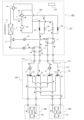
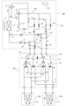
- FIG. 1 is a diagram showing an example of a circuit configuration of a refrigeration cycle device according to a first embodiment in a cooling only operation mode.
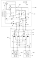
- 4 is a diagram showing the flows of a refrigerant and a heat medium in a cooling-dominated operation mode of the refrigeration cycle apparatus according to the first embodiment.
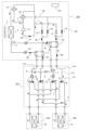
- FIG. 4 is a diagram showing the flows of a refrigerant and a heat medium in a full heating operation mode of the refrigeration cycle apparatus according to the first embodiment.
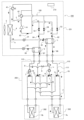
- FIG. 4 is a diagram showing the flows of a refrigerant and a heat medium in a heating-dominated operation mode of the refrigeration cycle apparatus according to the first embodiment.
- FIG. FIG. 11 is a diagram showing an example of a circuit configuration of a refrigeration cycle device according to a second embodiment.
- FIG. 11 is a diagram showing an example of a circuit configuration of a refrigeration cycle device according to a second embodiment.
- FIG. 11 is a diagram showing an example of a circuit configuration of a refrigeration cycle device according to a third embodiment.
- FIG. 11 is a diagram showing an example of a circuit configuration of a refrigeration cycle device according to a third embodiment.
- FIG. 13 is a diagram showing an example of a circuit configuration of a refrigeration cycle device according to a fourth embodiment.
- FIG. 13 is a diagram showing an example of a circuit configuration of a refrigeration cycle device according to a fourth embodiment.
- FIG. 13 is a diagram showing an example of a circuit configuration of a refrigeration cycle device according to a fifth embodiment.
- Fig. 1 is a diagram showing an example of a circuit configuration of a refrigeration cycle device according to embodiment 1 in a full cooling operation mode.
- solid arrows with black tips shown in Fig. 1 and Fig. 2 and subsequent figures indicate the flow direction of a refrigerant.
- dashed arrows with black tips shown in Fig. 1 and Fig. 2 and subsequent figures indicate the flow direction of a heat medium.
- the refrigeration cycle apparatus 200 when showing the open/closed state of an on-off valve or the like, an open flow path is shown in white, and a closed flow path is shown in black.
- the refrigeration cycle apparatus 200 includes a chiller-type heat source unit 201 and a heat medium circuit 110 through which the heat medium supplied from the heat source unit 201 circulates.
- the heat source unit 201 includes a refrigerant circuit 100 in which a refrigerant circulates, and a heat medium heat exchanger.
- the refrigerant circuit 100 and the heat medium heat exchanger are housed in the heat source unit 201.
- the heat medium heat exchanger functions as a condenser or evaporator in the refrigerant circuit 100, and exchanges heat between the refrigerant circulating in the refrigerant circuit 100 and a heat medium different from the refrigerant.
- the heat source unit 201 supplies the heat medium that has exchanged heat with the refrigerant in the heat medium heat exchanger to the outside of the heat source unit 201.
- the refrigerant circulating through the refrigerant circuit 100 is not particularly limited.
- the refrigerant circulating through the refrigerant circuit 100 is an olefin-based refrigerant, an ethylene-based refrigerant, an ethane-based refrigerant, propane, or dimethyl ether.
- the refrigerant circulating through the refrigerant circuit 100 is a mixed refrigerant that is a mixture of at least two of an olefin-based refrigerant, an ethylene-based refrigerant, an ethane-based refrigerant, propane, and dimethyl ether.
- the olefin-based refrigerant is tetrafluoropropene or the like.
- the tetrafluoropropene is HFO1234yf, HFO1234ze(E), or the like.
- the ethylene-based refrigerant is difluoroethylene or the like.
- the ethane-based refrigerant is tetrafluoroethane or the like.
- the heat medium that exchanges heat with the refrigerant in the heat medium heat exchanger is also not particularly limited.
- the heat medium is, for example, brine, antifreeze, and water.
- the brine is, for example, a calcium chloride aqueous solution, a sodium chloride aqueous solution, a magnesium chloride aqueous solution, or ethylene glycol.
- the first heat medium heat exchanger 1 and the second heat medium heat exchanger 2 are provided as heat medium heat exchangers.
- the refrigeration cycle device 200 may be provided with only one of the first heat medium heat exchanger 1 and the second heat medium heat exchanger 2. That is, the refrigeration cycle device 200 may be provided with only one heat medium heat exchanger.
- the other of the first heat medium heat exchanger 1 and the second heat medium heat exchanger 2 can function as an evaporator. That is, the heat source unit 201 according to this embodiment 1 is configured to be able to simultaneously supply a heated heat medium and a cooled heat medium.
- the refrigerant circuit 100 is configured as follows.
- the refrigerant circuit 100 includes a compressor 14, a first flow switching device 41, a second flow switching device 42, an outdoor heat exchanger 4, a first throttling device 21, a second throttling device 22, a first on-off valve 51, a second on-off valve 52, a third on-off valve 53, and a fourth on-off valve 54.
- the first heat medium heat exchanger 1 and the second heat medium heat exchanger 2 are also part of the configuration of the refrigerant circuit 100.
- the compressor 14 sucks in the refrigerant, compresses it, and discharges it in a high-temperature, high-pressure state.
- the compressor 14 may be a rotary compressor, a scroll compressor, a screw compressor, or a reciprocating compressor.
- the refrigerant discharge port of the compressor 14 is connected to a first flow path switching device 41 and a second flow path switching device 42.
- the refrigerant piping connected to the refrigerant discharge port of the compressor 14 branches into two refrigerant piping at the branching section a.
- One of the branched refrigerant piping is connected to the first flow path switching device 41, and the other of the branched refrigerant piping is connected to the second flow path switching device 42.
- the refrigerant suction port of the compressor 14 is also connected to the first flow path switching device 41 and the second flow path switching device 42.
- the refrigerant piping connected to the refrigerant suction port of the compressor 14 branches into two refrigerant piping.
- One of the branched refrigerant piping is connected to the first flow path switching device 41, and the other of the branched refrigerant piping is connected to the second flow path switching device 42.
- the first flow path switching device 41 is, for example, a four-way valve.
- the first flow path switching device 41 switches whether the refrigerant discharge port of the compressor 14 is connected to the outdoor heat exchanger 4.
- the first flow path switching device 41 also switches whether the refrigerant suction port of the compressor 14 is connected to the outdoor heat exchanger 4.
- the second flow path switching device 42 is, for example, a four-way valve.
- the second flow path switching device 42 switches whether the refrigerant discharge port of the compressor 14 is connected to the third on-off valve 53 and the fourth on-off valve 54.
- the first flow path switching device 41 also switches whether the refrigerant suction port of the compressor 14 is connected to the third on-off valve 53 and the fourth on-off valve 54.
- the outdoor heat exchanger 4 functions as an evaporator or a condenser.
- the outdoor heat exchanger 4 functions as an evaporator, it exchanges heat between the refrigerant that has flowed inside and the outdoor air, evaporating the refrigerant and vaporizing it.
- the outdoor heat exchanger 4 functions as a condenser, it exchanges heat between the refrigerant that has flowed inside and the outdoor air, condensing the refrigerant and liquefying it.
- an outdoor blower 5 that sends outdoor air to the outdoor heat exchanger 4 is placed adjacent to the outdoor heat exchanger 4.
- the outdoor blower 5 may be configured as a propeller fan, a line flow fan (registered trademark), a multi-blade centrifugal fan, or the like, based on the operating conditions such as the flow rate and static pressure of the outdoor air supplied to the outdoor heat exchanger 4.
- the first throttling device 21 and the second throttling device 22 function as pressure reducing valves or expansion valves, and expand the refrigerant to reduce its pressure.
- the first throttling device 21 and the second throttling device 22 are, for example, electric expansion valves capable of adjusting the flow rate of the refrigerant.
- the first throttling device 21 and the second throttling device 22 are connected in parallel to the outdoor heat exchanger 4. Specifically, the refrigerant piping connected to the outdoor heat exchanger 4 branches into two refrigerant piping at the branching section b.
- the first throttling device 21 and the second throttling device 22 are not limited to electric expansion valves.
- the first throttling device 21 and the second throttling device 22 may be mechanical expansion valves that use a diaphragm in the pressure receiving section.
- the first throttling device 21 and the second throttling device 22 may be partially composed of a capillary tube or the like.
- the first heat medium heat exchanger 1 and the second heat medium heat exchanger 2 function as a condenser or an evaporator in the refrigerant circuit 100.
- the first heat medium heat exchanger 1 and the second heat medium heat exchanger 2 function as an evaporator, they exchange heat between the refrigerant that has flowed into them and the heat medium, evaporating the refrigerant.
- the heat medium is cooled by the refrigerant.
- the first heat medium heat exchanger 1 and the second heat medium heat exchanger 2 function as a condenser, they exchange heat between the refrigerant that has flowed into them and the heat medium, condensing the refrigerant to liquefy it.
- the heat medium is heated by the refrigerant.
- One end of the refrigerant flow path of the first heat medium heat exchanger 1 is connected to the first throttling device 21.
- One end of the refrigerant flow path of the second heat medium heat exchanger 2 is connected to the second throttling device 22.
- the first on-off valve 51, the second on-off valve 52, the third on-off valve 53, and the fourth on-off valve 54 are, for example, two-way valves that open and close the flow path at the installation location.
- the first on-off valve 51 and the third on-off valve 53 are connected in parallel to the other end of the refrigerant flow path of the first heat medium heat exchanger 1.
- the second on-off valve 52 and the fourth on-off valve 54 are connected in parallel to the other end of the refrigerant flow path of the second heat medium heat exchanger 2.
- the first on-off valve 51 and the second on-off valve 52 are connected at a branch c to a pipe that connects the refrigerant intake port of the compressor 14 and the first flow path switching device 41.
- the third on-off valve 53 and the fourth on-off valve 54 are connected to the second flow path switching device 42.
- the heat medium circuit 110 circulates the heat medium supplied from the heat source unit 201. That is, the heat medium circuit 110 circulates the heat medium that has exchanged heat with the refrigerant in the heat medium heat exchanger.
- the heat medium circuit 110 includes a plurality of load side heat exchangers and a switching mechanism 70.
- the switching mechanism 70 switches the flow state of the heat medium in each of the load side heat exchangers.
- the heat medium circuit 110 according to the first embodiment includes the load side heat exchanger 3a and the load side heat exchanger 3b as a plurality of load side heat exchangers. Therefore, the switching mechanism 70 switches the flow state of the heat medium in the load side heat exchanger 3a and the load side heat exchanger 3b.
- the refrigeration cycle device 200 is used as an air conditioning device. Therefore, the load side heat exchanger 3a and the load side heat exchanger 3b are used as indoor heat exchangers that heat or cool indoor air.
- the load side heat exchanger 3a and the load side heat exchanger 3b are housed in different heat load units 202 and installed in a room that is to be air-conditioned.
- the example in which the refrigeration cycle apparatus 200 is used as an air-conditioning apparatus is one example of the use of the refrigeration cycle apparatus 200.
- the refrigeration cycle apparatus 200 may be used as something other than an air-conditioning apparatus.
- the load side heat exchanger 3a and the load side heat exchanger 3b may be provided under the floor to perform floor heating.
- the load side heat exchanger 3a and the load side heat exchanger 3b may be used as a heat exchanger that heats water stored in a hot water storage tank.
- the load side heat exchanger 3a and the load side heat exchanger 3b may be used as a heat exchanger that cools the air in a freezer compartment.
- the heat source unit 201 includes a first heat medium heat exchanger 1 and a second heat medium heat exchanger 2 as heat medium heat exchangers. Therefore, the heat medium circuit 110 according to the first embodiment includes a first circuit 111 that passes the heat medium through the first heat medium heat exchanger 1, and a second circuit 112 that passes the heat medium through the second heat medium heat exchanger 2.
- the switching mechanism 70 is configured to switch the flow state of the heat medium flowing out from the first heat medium heat exchanger 1 of each of the load side heat exchangers, and the flow state of the heat medium flowing out from the second heat medium heat exchanger 2 of each of the load side heat exchangers.
- the switching mechanism 70 includes a first flow path switching mechanism 71, a second flow path switching mechanism 72, a third flow path switching mechanism 73, and a fourth flow path switching mechanism 74.
- the first flow path switching mechanism 71, the second flow path switching mechanism 72, the third flow path switching mechanism 73, and the fourth flow path switching mechanism 74 are, for example, three-way valves.
- the first flow path switching mechanism 71, the second flow path switching mechanism 72, the third flow path switching mechanism 73, and the fourth flow path switching mechanism 74 are not limited to three-way valves.
- the first flow path switching mechanism 71, the second flow path switching mechanism 72, the third flow path switching mechanism 73, and the fourth flow path switching mechanism 74 may be configured by combining multiple two-way valves.
- the first flow path switching mechanism 71 is connected to the outlet of the heat medium flow path of the first heat medium heat exchanger 1.
- the first flow path switching mechanism 71 is also connected to the inlet of the load side heat exchanger 3a.
- the first flow path switching mechanism 71 is also connected to a pipe that connects the third flow path switching mechanism 73 and the load side heat exchanger 3b.
- the first flow path switching mechanism 71 communicates two of these three connections.
- the second flow path switching mechanism 72 is connected to the inlet of the heat medium flow path of the first heat medium heat exchanger 1. As described below, the first pump 6 is installed between the second flow path switching mechanism 72 and the inlet of the heat medium flow path of the first heat medium heat exchanger 1. Therefore, it can also be said that the second flow path switching mechanism 72 is connected to the first pump 6.
- the second flow path switching mechanism 72 is also connected to the outlet of the load side heat exchanger 3a.
- the second flow path switching mechanism 72 is also connected to a pipe that connects the fourth flow path switching mechanism 74 and the load side heat exchanger 3b. The second flow path switching mechanism 72 communicates two of these three connections.
- the third flow path switching mechanism 73 is connected to the outlet of the heat medium flow path of the second heat medium heat exchanger 2.
- the third flow path switching mechanism 73 is also connected to the piping that connects the first flow path switching mechanism 71 and the load side heat exchanger 3a.
- the third flow path switching mechanism 73 is also connected to the inlet of the load side heat exchanger 3b.
- the third flow path switching mechanism 73 communicates two of these three connections.
- the fourth flow path switching mechanism 74 is connected to the inlet of the heat medium flow path of the second heat medium heat exchanger 2. As described below, the second pump 7 is installed between the fourth flow path switching mechanism 74 and the inlet of the heat medium flow path of the second heat medium heat exchanger 2. Therefore, it can also be said that the fourth flow path switching mechanism 74 is connected to the second pump 7.
- the fourth flow path switching mechanism 74 is also connected to a pipe that connects the second flow path switching mechanism 72 and the load side heat exchanger 3a.
- the fourth flow path switching mechanism 74 is also connected to the outlet of the load side heat exchanger 3b.
- the fourth flow path switching mechanism 74 communicates two of these three connection destinations.
- the load side heat exchanger 3a When the load side heat exchanger 3a is in communication with the first heat medium heat exchanger 1, it becomes part of the first circuit 111.
- the flow path switching mechanism that connects the first heat medium heat exchanger 1 and the load side heat exchanger 3a also becomes part of the first circuit 111.
- the piping that connects the first heat medium heat exchanger 1 and the load side heat exchanger 3a also becomes part of the first circuit 111.
- the load side heat exchanger 3a is in communication with the second heat medium heat exchanger 2, it becomes part of the second circuit 112.
- the flow path switching mechanism that connects the second heat medium heat exchanger 2 and the load side heat exchanger 3a also becomes part of the second circuit 112.
- the piping that connects the second heat medium heat exchanger 2 and the load side heat exchanger 3a also becomes part of the second circuit 112.
- the load side heat exchanger 3b when the load side heat exchanger 3b is in communication with the first heat medium heat exchanger 1, it becomes part of the first circuit 111.
- the flow path switching mechanism that connects the first heat medium heat exchanger 1 and the load side heat exchanger 3b also becomes part of the first circuit 111.
- the piping that connects the first heat medium heat exchanger 1 and the load side heat exchanger 3b also becomes part of the first circuit 111.
- the load side heat exchanger 3b is in communication with the second heat medium heat exchanger 2, it becomes part of the second circuit 112.
- the flow path switching mechanism that connects the second heat medium heat exchanger 2 and the load side heat exchanger 3b also becomes part of the second circuit 112.
- the piping that connects the second heat medium heat exchanger 2 and the load side heat exchanger 3b also becomes part of the second circuit 112.
- the refrigeration cycle device 200 includes a relay unit 203.
- the above-mentioned switching mechanism 70 is housed in the relay unit 203.
- the refrigeration cycle device 200 includes a relay unit 203 in which the switching mechanism 70 is housed.
- the heat medium circuit 110 is provided with a pump as a configuration for circulating the heat medium in the heat medium circuit 110.
- the heat medium circuit 110 is provided with a first pump 6 provided in the first circuit 111 and a second pump 7 provided in the second circuit 112 as pumps.
- the first pump 6 is provided at a location where the heat medium flows into the first heat medium heat exchanger 1 of the first circuit 111.
- the first pump 6 discharges the heat medium that flows into the first heat medium heat exchanger 1.
- the second pump 7 is provided at a location where the heat medium flows into the second heat medium heat exchanger 2 of the second circuit 112.
- the second pump 7 discharges the heat medium that flows into the second heat medium heat exchanger 2.
- the first pump 6 and the second pump 7 are stored in the relay unit 203.
- the refrigeration cycle device 200 is also provided with a control device 210 that controls the operating state of the refrigeration cycle device 200.
- the control device 210 starts and stops the compressor 14.
- the control device 210 may control the rotation speed of the compressor 14 when the compressor 14 is driven. This allows the amount of refrigerant discharged from the compressor 14 to be adjusted.
- the control device 210 also switches the flow paths of the first flow path switching device 41 and the second flow path switching device 42.
- the control device 210 also starts and stops the outdoor blower 5.
- the control device 210 may control the rotation speed of the outdoor blower 5 when the outdoor blower 5 is driven.
- the control device 210 also controls the opening degree of the first throttling device 21 and the second throttling device 22.
- the control device 210 also controls the open/close states of the first opening/closing valve 51, the second opening/closing valve 52, the third opening/closing valve 53, and the fourth opening/closing valve 54.
- the control device 210 also switches the flow path of the switching mechanism 70. That is, the control device 210 switches the flow paths of the first flow path switching mechanism 71, the second flow path switching mechanism 72, the third flow path switching mechanism 73, and the fourth flow path switching mechanism 74.
- the control device 210 also starts and stops the first pump 6 and the second pump 7.
- the control device 210 may control the rotation speeds of the first pump 6 and the second pump 7 when the first pump 6 and the second pump 7 are driven. This makes it possible to adjust the amount of refrigerant discharged from the first pump 6 and the second pump 7.
- Such a control device 210 is composed of dedicated hardware, or a CPU (Central Processing Unit) that executes programs stored in memory.
- a CPU Central Processing Unit
- a CPU is also called a central processing unit, processing unit, arithmetic unit, microprocessor, microcomputer, or processor.
- control device 210 When the control device 210 is dedicated hardware, the control device 210 is, for example, a single circuit, a composite circuit, an ASIC (Application Specific Integrated Circuit), an FPGA (Field-Programmable Gate Array), or a combination of these. Each of the functional units realized by the control device 210 may be realized by separate hardware, or each functional unit may be realized by a single piece of hardware.
- ASIC Application Specific Integrated Circuit
- FPGA Field-Programmable Gate Array
- each function executed by the control device 210 is realized by software, firmware, or a combination of software and firmware.
- Software and firmware are written as programs and stored in memory.
- the CPU realizes each function of the control device 210 by reading and executing the programs stored in the memory.
- the memory is, for example, a non-volatile or volatile semiconductor memory such as a RAM, ROM, flash memory, EPROM, or EEPROM.
- control device 210 may be realized by dedicated hardware, and some by software or firmware.
- the control device 210 is stored in the heat source unit 201, but at least some of the configuration of the control device 210 may be stored in a location other than the heat source unit 201.
- the configuration of the control device 210 may be stored in a distributed manner in the heat source unit 201 and the relay unit 203.
- the heat medium circuit is configured as follows. Specifically, the heat medium circuit is equipped with a main pipe through which the heat medium flowing out of the heat source unit flows and which returns the heat medium to the heat source unit. Each of the load-side heat exchangers is connected to the main pipe via a branch pipe. In addition, the flow state of the heat medium in each of the load-side heat exchangers is switched by a switching mechanism provided in the branch pipe connected to each of the load-side heat exchangers. In other words, whether or not to flow the heat medium in each of the load-side heat exchangers is switched by a switching mechanism provided in the branch pipe connected to each of the load-side heat exchangers.
- the main pipe needs to be thick in order to suppress the pressure loss that occurs when the heat medium flows through the main pipe.
- a conventional refrigeration cycle apparatus equipped with a chiller-type heat source unit and multiple load-side heat exchangers needs to have a long and thick main pipe installed on-site.
- the heat medium circuit of a conventional refrigeration cycle device equipped with a chiller-type heat source unit and multiple load-side heat exchangers has a long and thick main pipe, so when sealing the heat medium in the heat medium circuit, it also takes a long time to bleed air from the heat medium circuit. This work is also a factor that takes a long time to install a refrigeration cycle device on site.
- the heat medium circuit of a conventional refrigeration cycle device equipped with a chiller-type heat source unit and multiple load-side heat exchangers has a long and thick main pipe, so the amount of heat medium to be sealed in the heat medium circuit is also large.
- the heat source unit 201, the relay unit 203, and the heat load unit 202 are installed in a specified location. Then, the heat source unit 201 and the relay unit 203 are connected by piping, and the relay unit 203 and the heat load unit 202 are connected by piping.
- the piping corresponding to the main pipe of the heat medium circuit of the conventional refrigeration cycle device is the piping connecting the heat medium heat exchanger and the switching mechanism 70. Therefore, in the refrigeration cycle device 200 according to the first embodiment, the piping connecting the heat source unit 201 and the relay unit 203 is part of the piping corresponding to the main pipe of the conventional refrigeration cycle device.
- the remaining part of the piping corresponding to the main pipe of the conventional refrigeration cycle device is stored in the heat source unit 201 and the relay unit 203. Therefore, the remaining piping, which corresponds to the main pipe of a conventional refrigeration cycle device, is completed at the time when the heat source unit 201 and relay unit 203 are installed.
- the refrigeration cycle device 200 according to the first embodiment the piping corresponding to the main pipe of the conventional refrigeration cycle device to be installed on-site is shorter than the main pipe of the heat medium circuit of the conventional refrigeration cycle device. Therefore, the refrigeration cycle device 200 according to the first embodiment can reduce the installation time on-site compared to the conventional one. Furthermore, in the refrigeration cycle device 200 according to the first embodiment, the installation of the switching mechanism 70 is completed at the time when the relay unit 203 is installed. In this respect, the refrigeration cycle device 200 according to the first embodiment can reduce the installation time on-site compared to the conventional one.
- the refrigeration cycle device 200 according to the first embodiment is configured to connect the relay unit 203 and the heat load unit 202 with a pipe, the piping corresponding to the main pipe of the conventional refrigeration cycle device can be shortened. Furthermore, since the refrigeration cycle device 200 according to the first embodiment can shorten the piping corresponding to the main pipe of the conventional refrigeration cycle device, the pressure loss generated when the heat medium flows can be suppressed. Therefore, the refrigeration cycle device 200 according to the first embodiment can also reduce the diameter of the piping corresponding to the main pipe of the conventional refrigeration cycle device. Therefore, the refrigeration cycle apparatus 200 according to the first embodiment can reduce the time required to bleed air from the heat medium circuit 110 when sealing the heat medium in the heat medium circuit 110, compared to the conventional method.
- the refrigeration cycle apparatus 200 according to the first embodiment can also reduce the on-site installation time compared to the conventional method. Furthermore, the refrigeration cycle apparatus 200 according to the first embodiment can shorten the piping equivalent to the main pipe of a conventional refrigeration cycle apparatus, and can also reduce the diameter of the piping, so that the amount of heat medium sealed in the heat medium circuit 110 can also be reduced compared to the conventional method.
- the refrigeration cycle device 200 can operate in an all-cooling operation mode, an all-heating operation mode, a cooling-dominated operation mode, and a heating-dominated operation mode.
- the all-cooling operation mode is an operation mode in which all operating heat load units 202 perform cooling operation.
- the all-heating operation mode is an operation mode in which all operating heat load units 202 perform heating operation.
- the cooling-dominated operation mode is an operation mode in which heat load units 202 performing cooling operation and heat load units 202 performing heating operation are mixed, and the cooling load is greater than the heating load.
- the heating-dominated operation mode is an operation mode in which heat load units 202 performing cooling operation and heat load units 202 performing heating operation are mixed, and the heating load is greater than the cooling load.
- Fig. 1 illustrates an example in which a cooling load is generated in both the load side heat exchanger 3a and the load side heat exchanger 3b.
- the control device 210 switches the flow path of the first flow path switching device 41 to a flow path in which the refrigerant discharge port of the compressor 14 communicates with the outdoor heat exchanger 4.
- the control device 210 also switches the flow path of the second flow path switching device 42 to a flow path in which the refrigerant suction port of the compressor 14 communicates with the third on-off valve 53 and the fourth on-off valve 54.
- the control device 210 also opens the first on-off valve 51 and the second on-off valve 52, and closes the third on-off valve 53 and the fourth on-off valve 54.
- the control device 210 also switches the flow path of the first flow path switching mechanism 71 to a flow path in which the outlet of the heat medium flow path of the first heat medium heat exchanger 1 communicates with the load side heat exchanger 3a.
- the control device 210 also switches the flow path of the second flow path switching mechanism 72 to a flow path in which the inlet of the heat medium flow path of the first heat medium heat exchanger 1 communicates with the load side heat exchanger 3a.
- the control device 210 also switches the flow path of the third flow path switching mechanism 73 to a flow path that connects the outlet of the heat medium flow path of the second heat medium heat exchanger 2 with the load side heat exchanger 3b.
- the control device 210 also switches the flow path of the fourth flow path switching mechanism 74 to a flow path that connects the inlet of the heat medium flow path of the second heat medium heat exchanger 2 with the load side heat exchanger 3b.
- the control device 210 also starts the compressor 14, the first pump 6, the second pump 7, and the outdoor blower 5.
- the refrigerant flows in the refrigerant circuit 100 as follows.
- the compressor 14 compresses low-temperature, low-pressure refrigerant and discharges it as high-temperature, high-pressure gas refrigerant.
- the high-temperature, high-pressure gas refrigerant discharged from the compressor 14 flows into the outdoor heat exchanger 4, which functions as a condenser, via branch section a and the first flow switching device 41.
- the high-temperature, high-pressure gas refrigerant that flows into the outdoor heat exchanger 4 then becomes high-pressure liquid refrigerant while releasing heat to the outdoor air.
- the high-pressure liquid refrigerant that flows out of the outdoor heat exchanger 4 branches at branch section b and flows into the first throttling device 21 and the second throttling device 22.
- the high-pressure liquid refrigerant that flows into the first throttling device 21 expands to become a low-temperature, low-pressure, two-phase gas-liquid refrigerant, which then flows into the first heat medium heat exchanger 1, which functions as an evaporator.
- the low-temperature, low-pressure, two-phase gas-liquid refrigerant that flows into the first heat medium heat exchanger 1 absorbs heat from the heat medium, cooling the heat medium, and becomes a low-pressure gas refrigerant.
- the high-pressure liquid refrigerant that flows into the second throttling device 22 expands to become a low-temperature, low-pressure, two-phase gas-liquid refrigerant, which then flows into the second heat medium heat exchanger 2, which functions as an evaporator.
- the low-temperature, low-pressure, two-phase gas-liquid refrigerant that flows into the second heat medium heat exchanger 2 absorbs heat from the heat medium, cooling the heat medium, and becomes a low-pressure gas refrigerant.
- the low-pressure gas refrigerant flowing out of the first heat medium heat exchanger 1 passes through the first on-off valve 51.
- the low-pressure gas refrigerant flowing out of the second heat medium heat exchanger 2 passes through the second on-off valve 52. These low-pressure gas refrigerants then pass through the branching section c and are sucked back into the compressor 14.
- the heat medium flows in the heat medium circuit 110 as follows.
- the heat medium discharged from the first pump 6 flows into the heat source unit 201 and into the first heat medium heat exchanger 1.
- the heat medium that flows into the first heat medium heat exchanger 1 is cooled by the refrigerant and flows out of the first heat medium heat exchanger 1.
- the heat medium that flows out of the first heat medium heat exchanger 1 flows into the relay unit 203 and passes through the first flow path switching mechanism 71.
- the heat medium that passes through the first flow path switching mechanism 71 flows into the heat load unit 202 and into the load side heat exchanger 3a.
- the heat medium that flows into the load side heat exchanger 3a cools the indoor air by absorbing heat from the indoor air.
- the heat medium that flows out of the load side heat exchanger 3a flows into the relay unit 203 and passes through the second flow path switching mechanism 72.
- the heat medium that passes through the second flow path switching mechanism 72 is sucked back into the first pump 6.
- the heat medium discharged from the second pump 7 flows into the heat source unit 201 and into the second heat medium heat exchanger 2.
- the heat medium that flows into the second heat medium heat exchanger 2 is cooled by the refrigerant and flows out of the second heat medium heat exchanger 2.
- the heat medium that flows out of the second heat medium heat exchanger 2 flows into the relay unit 203 and passes through the third flow path switching mechanism 73.
- the heat medium that passes through the third flow path switching mechanism 73 flows into the heat load unit 202 and flows into the load side heat exchanger 3b.
- the heat medium that flows into the load side heat exchanger 3b cools the indoor air by absorbing heat from the indoor air.
- the heat medium that flows out of the load side heat exchanger 3b flows into the relay unit 203 and passes through the fourth flow path switching mechanism 74.
- the heat medium that passes through the fourth flow path switching mechanism 74 is sucked back into the second pump 7.
- the above-mentioned cycle is repeated in the refrigerant circuit 100 and the heat medium circuit 110 during operation in the full cooling operation mode.
- FIG. 2 is a diagram showing the flow of the refrigerant and the heat medium in the cooling-dominated operation mode of the refrigeration cycle device according to embodiment 1.
- the cooling-dominated operation mode will be described using an example in which the heat load unit 202 housed in the load-side heat exchanger 3a performs cooling operation and the heat load unit 202 housed in the load-side heat exchanger 3b performs heating operation.
- Fig. 2 illustrates an example in which a cold heat load is generated in the load-side heat exchanger 3a and a warm heat load is generated in the load-side heat exchanger 3b.
- the control device 210 switches the flow path of the first flow path switching device 41 to a flow path in which the refrigerant discharge port of the compressor 14 communicates with the outdoor heat exchanger 4.
- the control device 210 also switches the flow path of the second flow path switching device 42 to a flow path in which the refrigerant discharge port of the compressor 14 communicates with the third on-off valve 53 and the fourth on-off valve 54.
- the control device 210 also opens the first on-off valve 51 and the fourth on-off valve 54, and closes the second on-off valve 52 and the third on-off valve 53.
- the control device 210 also switches the flow path of the first flow path switching mechanism 71 to a flow path in which the outlet of the heat medium flow path of the first heat medium heat exchanger 1 communicates with the load side heat exchanger 3a.
- the control device 210 also switches the flow path of the second flow path switching mechanism 72 to a flow path in which the inlet of the heat medium flow path of the first heat medium heat exchanger 1 communicates with the load side heat exchanger 3a.
- the control device 210 also switches the flow path of the third flow path switching mechanism 73 to a flow path that connects the outlet of the heat medium flow path of the second heat medium heat exchanger 2 with the load side heat exchanger 3b.
- the control device 210 also switches the flow path of the fourth flow path switching mechanism 74 to a flow path that connects the inlet of the heat medium flow path of the second heat medium heat exchanger 2 with the load side heat exchanger 3b.
- the control device 210 also starts the compressor 14, the first pump 6, the second pump 7, and the outdoor blower 5.
- the refrigerant flows in the refrigerant circuit 100 as follows.
- the compressor 14 compresses low-temperature, low-pressure refrigerant and discharges it as high-temperature, high-pressure gas refrigerant.
- the high-temperature, high-pressure gas refrigerant discharged from the compressor 14 branches at branch point a into a flow that flows into the outdoor heat exchanger 4 via the first flow switching device 41 and a flow that flows into the second flow switching device 42.
- the refrigerant flowing out of the outdoor heat exchanger 4 flows toward the branch b.
- the refrigerant flowing out of the second heat medium heat exchanger 2 also flows toward the branch b through the second throttling device 22. Then, these refrigerants merge at the branch b and flow into the first throttling device 21.
- the refrigerant flowing into the first throttling device 21 expands to become a low-temperature, low-pressure, two-phase gas-liquid refrigerant, and flows into the first heat medium heat exchanger 1, which functions as an evaporator.
- the low-temperature, low-pressure, two-phase gas-liquid refrigerant flowing into the first heat medium heat exchanger 1 absorbs heat from the heat medium, cooling it and becoming a low-pressure gas refrigerant.
- the low-pressure gas refrigerant flowing out of the first heat medium heat exchanger 1 passes through the first opening and closing valve 51, then passes through the branch c and is sucked back into the compressor 14.
- the heat medium flows in the heat medium circuit 110 as follows.
- the heat medium discharged from the first pump 6 flows into the heat source unit 201 and into the first heat medium heat exchanger 1.
- the heat medium that flows into the first heat medium heat exchanger 1 is cooled by the refrigerant and flows out of the first heat medium heat exchanger 1.
- the heat medium that flows out of the first heat medium heat exchanger 1 flows into the relay unit 203 and passes through the first flow path switching mechanism 71.
- the heat medium that passes through the first flow path switching mechanism 71 flows into the heat load unit 202 and into the load side heat exchanger 3a.
- the heat medium that flows into the load side heat exchanger 3a cools the indoor air by absorbing heat from the indoor air.
- the heat medium that flows out of the load side heat exchanger 3a flows into the relay unit 203 and passes through the second flow path switching mechanism 72.
- the heat medium that passes through the second flow path switching mechanism 72 is sucked back into the first pump 6.
- the heat medium discharged from the second pump 7 flows into the heat source unit 201 and into the second heat medium heat exchanger 2.
- the heat medium that flows into the second heat medium heat exchanger 2 is heated by the refrigerant and flows out of the second heat medium heat exchanger 2.
- the heat medium that flows out of the second heat medium heat exchanger 2 flows into the relay unit 203 and passes through the third flow path switching mechanism 73.
- the heat medium that passes through the third flow path switching mechanism 73 flows into the heat load unit 202 and flows into the load side heat exchanger 3b.
- the heat medium that flows into the load side heat exchanger 3b heats the indoor air by releasing heat to the indoor air.
- the heat medium that flows out of the load side heat exchanger 3b flows into the relay unit 203 and passes through the fourth flow path switching mechanism 74.
- the heat medium that passes through the fourth flow path switching mechanism 74 is sucked back into the second pump 7.
- the above-mentioned cycle is repeated in the refrigerant circuit 100 and the heat medium circuit 110 during operation in the cooling-dominated operation mode.
- FIG. 3 is a diagram showing the flow of the refrigerant and the heat medium in the full heating operation mode of the refrigeration cycle device according to embodiment 1.
- the full heating operation mode will be described using an example in which all heat load units 202 perform heating operation.
- Fig. 3 illustrates a case in which a warm heat load is generated in both the load side heat exchanger 3a and the load side heat exchanger 3b.
- the control device 210 switches the flow path of the first flow path switching device 41 to a flow path in which the refrigerant intake of the compressor 14 communicates with the outdoor heat exchanger 4.
- the control device 210 also switches the flow path of the second flow path switching device 42 to a flow path in which the refrigerant discharge of the compressor 14 communicates with the third on-off valve 53 and the fourth on-off valve 54.
- the control device 210 also closes the first on-off valve 51 and the second on-off valve 52, and opens the third on-off valve 53 and the fourth on-off valve 54.
- the control device 210 also switches the flow path of the first flow path switching mechanism 71 to a flow path in which the outlet of the heat medium flow path of the first heat medium heat exchanger 1 communicates with the load side heat exchanger 3a.
- the control device 210 also switches the flow path of the second flow path switching mechanism 72 to a flow path in which the inlet of the heat medium flow path of the first heat medium heat exchanger 1 communicates with the load side heat exchanger 3a.
- the control device 210 also switches the flow path of the third flow path switching mechanism 73 to a flow path that connects the outlet of the heat medium flow path of the second heat medium heat exchanger 2 with the load side heat exchanger 3b.
- the control device 210 also switches the flow path of the fourth flow path switching mechanism 74 to a flow path that connects the inlet of the heat medium flow path of the second heat medium heat exchanger 2 with the load side heat exchanger 3b.
- the control device 210 also starts the compressor 14, the first pump 6, the second pump 7, and the outdoor blower 5.
- the refrigerant flows in the refrigerant circuit 100 as follows.
- the compressor 14 compresses low-temperature, low-pressure refrigerant and discharges it as high-temperature, high-pressure gas refrigerant.
- the high-temperature, high-pressure gas refrigerant discharged from the compressor 14 flows into the third on-off valve 53 and the fourth on-off valve 54 via the second flow path switching device 42.
- the high-pressure liquid refrigerant that flows into the third opening/closing valve 53 flows into the first heat medium heat exchanger 1, which functions as a condenser.
- the high-temperature, high-pressure gas refrigerant that flows into the first heat medium heat exchanger 1 becomes a high-pressure liquid refrigerant while heating the heat medium by dissipating heat to the heat medium.
- the high-pressure liquid refrigerant that flows out of the first heat medium heat exchanger 1 flows into the first throttling device 21, where it expands and becomes a low-temperature, low-pressure gas-liquid two-phase refrigerant.
- the high-pressure liquid refrigerant that flows into the fourth opening/closing valve 54 flows into the second heat medium heat exchanger 2, which functions as a condenser.
- the high-temperature, high-pressure gas refrigerant that flows into the second heat medium heat exchanger 2 becomes a high-pressure liquid refrigerant while heating the heat medium by dissipating heat to the heat medium.
- the high-pressure liquid refrigerant that flows out of the second heat medium heat exchanger 2 flows into the second throttling device 22, where it expands and becomes a low-temperature, low-pressure gas-liquid two-phase refrigerant.
- the low-temperature, low-pressure, two-phase gas-liquid refrigerant flowing out of the first throttling device 21 and the low-temperature, low-pressure, two-phase gas-liquid refrigerant flowing out of the second throttling device 22 join at branch point b and flow into the outdoor heat exchanger 4, which functions as an evaporator.
- the low-temperature, low-pressure, two-phase gas-liquid refrigerant that flows into the outdoor heat exchanger 4 absorbs heat from the outdoor air and becomes low-pressure gas refrigerant.
- the low-pressure gas refrigerant that flows out of the outdoor heat exchanger 4 passes through the first flow switching device 41 and is then sucked back into the compressor 14.
- the heat medium flows in the heat medium circuit 110 as follows.
- the heat medium discharged from the first pump 6 flows into the heat source unit 201 and into the first heat medium heat exchanger 1.
- the heat medium that flows into the first heat medium heat exchanger 1 is heated by the refrigerant and flows out of the first heat medium heat exchanger 1.
- the heat medium that flows out of the first heat medium heat exchanger 1 flows into the relay unit 203 and passes through the first flow path switching mechanism 71.
- the heat medium that passes through the first flow path switching mechanism 71 flows into the heat load unit 202 and into the load side heat exchanger 3a.
- the heat medium that flows into the load side heat exchanger 3a releases heat to the indoor air, thereby heating the indoor air.
- the heat medium that flows out of the load side heat exchanger 3a flows into the relay unit 203 and passes through the second flow path switching mechanism 72.
- the heat medium that passes through the second flow path switching mechanism 72 is sucked back into the first pump 6.
- the heat medium discharged from the second pump 7 flows into the heat source unit 201 and into the second heat medium heat exchanger 2.
- the heat medium that flows into the second heat medium heat exchanger 2 is heated by the refrigerant and flows out of the second heat medium heat exchanger 2.
- the heat medium that flows out of the second heat medium heat exchanger 2 flows into the relay unit 203 and passes through the third flow path switching mechanism 73.
- the heat medium that passes through the third flow path switching mechanism 73 flows into the heat load unit 202 and flows into the load side heat exchanger 3b.
- the heat medium that flows into the load side heat exchanger 3b heats the indoor air by releasing heat to the indoor air.
- the heat medium that flows out of the load side heat exchanger 3b flows into the relay unit 203 and passes through the fourth flow path switching mechanism 74.
- the heat medium that passes through the fourth flow path switching mechanism 74 is sucked back into the second pump 7.
- the above-mentioned cycle is repeated in the refrigerant circuit 100 and the heat medium circuit 110 during operation in the full heating operation mode.
- FIG. 4 is a diagram showing the flow of the refrigerant and the heat medium in the heating-dominated operation mode of the refrigeration cycle device according to embodiment 1.
- the heating-dominated operation mode will be described using an example in which the heat load unit 202 housed in the load side heat exchanger 3a performs cooling operation and the heat load unit 202 housed in the load side heat exchanger 3b performs heating operation.
- Fig. 4 illustrates an example in which a cold heat load is generated in the load side heat exchanger 3a and a hot heat load is generated in the load side heat exchanger 3b.
- the control device 210 switches the flow path of the first flow path switching device 41 to a flow path in which the refrigerant intake of the compressor 14 communicates with the outdoor heat exchanger 4.
- the control device 210 also switches the flow path of the second flow path switching device 42 to a flow path in which the refrigerant discharge of the compressor 14 communicates with the third on-off valve 53 and the fourth on-off valve 54.
- the control device 210 also opens the first on-off valve 51 and the fourth on-off valve 54, and closes the second on-off valve 52 and the third on-off valve 53.
- the control device 210 also switches the flow path of the first flow path switching mechanism 71 to a flow path in which the outlet of the heat medium flow path of the first heat medium heat exchanger 1 communicates with the load side heat exchanger 3a.
- the control device 210 also switches the flow path of the second flow path switching mechanism 72 to a flow path in which the inlet of the heat medium flow path of the first heat medium heat exchanger 1 communicates with the load side heat exchanger 3a.
- the control device 210 also switches the flow path of the third flow path switching mechanism 73 to a flow path that connects the outlet of the heat medium flow path of the second heat medium heat exchanger 2 with the load side heat exchanger 3b.
- the control device 210 also switches the flow path of the fourth flow path switching mechanism 74 to a flow path that connects the inlet of the heat medium flow path of the second heat medium heat exchanger 2 with the load side heat exchanger 3b.
- the control device 210 also starts the compressor 14, the first pump 6, the second pump 7, and the outdoor blower 5.
- the refrigerant flows in the refrigerant circuit 100 as follows.
- the compressor 14 compresses low-temperature, low-pressure refrigerant and discharges it as high-temperature, high-pressure gas refrigerant.
- the high-temperature, high-pressure gas refrigerant discharged from the compressor 14 flows into the fourth on-off valve 54 via the second flow switching device 42.
- the high-pressure liquid refrigerant that flows into the fourth on-off valve 54 flows into the second heat medium heat exchanger 2, which functions as a condenser.
- the high-temperature, high-pressure gas refrigerant that flows into the second heat medium heat exchanger 2 dissipates heat to the heat medium, heating the heat medium and becoming a high-pressure liquid refrigerant.
- the high-pressure liquid refrigerant that flows out of the second heat medium heat exchanger 2 flows into the second throttling device 22 and expands to become a low-temperature, low-pressure gas-liquid two-phase refrigerant.
- the low-temperature, low-pressure, two-phase gas-liquid refrigerant flowing out of the second throttling device 22 branches at branch point b. Then, a portion of the low-temperature, low-pressure, two-phase gas-liquid refrigerant flowing out of the second throttling device 22 passes through the first throttling device 21 and flows into the first heat medium heat exchanger 1, which functions as an evaporator. In addition, the remaining portion of the low-temperature, low-pressure, two-phase gas-liquid refrigerant flowing out of the second throttling device 22 flows into the outdoor heat exchanger 4, which functions as an evaporator.
- the low-temperature, low-pressure, two-phase gas-liquid refrigerant that flows into the first heat medium heat exchanger 1 absorbs heat from the heat medium, cooling it and becoming a low-pressure gas refrigerant.
- the low-temperature, low-pressure, two-phase gas-liquid refrigerant that flows into the outdoor heat exchanger 4 absorbs heat from the outdoor air and becomes a low-pressure gas refrigerant.
- the low-pressure gas refrigerant that flows out of the first heat medium heat exchanger 1 passes through the first on-off valve 51 and flows toward the branching section c.
- the low-pressure gas refrigerant that flows out of the outdoor heat exchanger 4 also passes through the first flow switching device 41 and flows toward the branching section c.
- the heat medium flows in the heat medium circuit 110 as follows.
- the heat medium discharged from the first pump 6 flows into the heat source unit 201 and into the first heat medium heat exchanger 1.
- the heat medium that flows into the first heat medium heat exchanger 1 is cooled by the refrigerant and flows out of the first heat medium heat exchanger 1.
- the heat medium that flows out of the first heat medium heat exchanger 1 flows into the relay unit 203 and passes through the first flow path switching mechanism 71.
- the heat medium that passes through the first flow path switching mechanism 71 flows into the heat load unit 202 and into the load side heat exchanger 3a.
- the heat medium that flows into the load side heat exchanger 3a cools the indoor air by absorbing heat from the indoor air.
- the heat medium that flows out of the load side heat exchanger 3a flows into the relay unit 203 and passes through the second flow path switching mechanism 72.
- the heat medium that passes through the second flow path switching mechanism 72 is sucked back into the first pump 6.
- the heat medium discharged from the second pump 7 flows into the heat source unit 201 and into the second heat medium heat exchanger 2.
- the heat medium that flows into the second heat medium heat exchanger 2 is heated by the refrigerant and flows out of the second heat medium heat exchanger 2.
- the heat medium that flows out of the second heat medium heat exchanger 2 flows into the relay unit 203 and passes through the third flow path switching mechanism 73.
- the heat medium that passes through the third flow path switching mechanism 73 flows into the heat load unit 202 and flows into the load side heat exchanger 3b.
- the heat medium that flows into the load side heat exchanger 3b heats the indoor air by releasing heat to the indoor air.
- the heat medium that flows out of the load side heat exchanger 3b flows into the relay unit 203 and passes through the fourth flow path switching mechanism 74.
- the heat medium that passes through the fourth flow path switching mechanism 74 is sucked back into the second pump 7.
- the above-mentioned cycle is repeated in the refrigerant circuit 100 and the heat medium circuit 110 during operation in the heating-dominated operation mode.
- the refrigeration cycle apparatus 200 includes a heat source unit 201.
- the heat source unit 201 has a heat medium heat exchanger in which the refrigerant circulating in the refrigerant circuit 100 exchanges heat with a heat medium different from the refrigerant, and is configured to supply the heat medium that has exchanged heat with the refrigerant in the heat medium heat exchanger to the outside.
- the refrigeration cycle apparatus 200 also includes a heat medium circuit 110 in which the heat medium supplied from the heat source unit 201 circulates.
- the heat medium circuit 110 includes a plurality of load side heat exchangers and a switching mechanism 70 that switches the flow state of the heat medium in each of the load side heat exchangers.
- the refrigeration cycle apparatus 200 also includes a relay unit 203 in which the switching mechanism 70 is housed.
- the piping equivalent to the main pipe of a conventional refrigeration cycle device that is to be installed on-site is the piping that connects the heat source unit and the relay unit. Therefore, in the refrigeration cycle device 200 configured in this manner, the piping equivalent to the conventional main pipe that is to be installed on-site is shorter than the conventional main pipe. Therefore, the refrigeration cycle device 200 configured in this manner can reduce the installation time on-site compared to the conventional case.
- Embodiment 2 By providing the bypass circuit shown in the second embodiment to the refrigeration cycle apparatus 200 shown in the first embodiment, the reliability of the refrigeration cycle apparatus 200 is improved. Note that matters not specifically mentioned in the second embodiment are the same as those in the first embodiment. In the second embodiment, components that perform the same functions as those shown in the first embodiment are denoted by the same reference numerals as those in the first embodiment.
- FIGS. 5 and 6 are diagrams showing an example of the circuit configuration of the refrigeration cycle device according to the second embodiment.
- FIG. 5 shows the operating state of the refrigeration cycle device 200 when performing freeze protection operation in the cooling only operation mode.
- FIG. 5 also shows the operating state of the refrigeration cycle device 200 when performing freeze protection operation in the cooling main operation mode.
- the heat medium circuit 110 of the refrigeration cycle device 200 includes a bypass circuit 8.
- the bypass circuit 8 connects a portion between the first heat medium heat exchanger 1 and the first pump 6 of the first circuit 111 and a portion between the second heat medium heat exchanger 2 and the second pump 7 of the second circuit 112.
- one end of the bypass circuit 8 is connected to a portion between the first heat medium heat exchanger 1 and the first pump 6 of the first circuit 111.
- the other end of the bypass circuit 8 is connected to a portion between the second heat medium heat exchanger 2 and the second pump 7 of the second circuit 112.
- the bypass circuit 8 is stored in the relay unit 203.
- the portion where the bypass circuit 8 is connected to the portion between the first heat medium heat exchanger 1 and the first pump 6 of the first circuit 111 is referred to as a branch portion e.
- the control device 210 of the refrigeration cycle device 200 executes a freeze protection operation when a specified operating condition is met to prevent the heat medium from freezing in the heat medium heat exchanger.
- the operating condition is, for example, a condition in which the temperature of the refrigerant flowing into the heat medium heat exchanger functioning as an evaporator is equal to or lower than a first specified temperature.
- the operating condition is a condition in which the temperature of the heat medium flowing out of the heat medium heat exchanger functioning as an evaporator is equal to or lower than a second specified temperature.
- the pressure of the refrigerant flowing into the heat medium heat exchanger functioning as an evaporator and the pressure of the refrigerant flowing out of the heat medium heat exchanger functioning as an evaporator are correlated with the evaporation temperature of the refrigerant flowing through the heat medium heat exchanger.
- the operating condition may be, for example, a condition in which the pressure of the refrigerant flowing into the heat medium heat exchanger functioning as an evaporator is equal to or lower than a specified pressure.
- the operating condition may be one in which the pressure of the refrigerant flowing out of the heat medium heat exchanger functioning as an evaporator is equal to or lower than a specified pressure.
- the refrigeration cycle device 200 includes a sensor 81, which is a temperature sensor or a pressure sensor, located between the first throttling device 21 and the first heat medium heat exchanger 1 in the refrigerant circuit 100. This allows the control device 210 to detect, based on the detection value of the sensor 81, that the first heat medium heat exchanger 1 is in the operating condition for freeze protection operation when the first heat medium heat exchanger 1 functions as an evaporator.
- the refrigeration cycle device 200 includes a sensor 82, which is a pressure sensor, located between the first heat medium heat exchanger 1 and the first opening/closing valve 51 in the refrigerant circuit 100. This allows the control device 210 to detect, based on the detection value of the sensor 82, that the first heat medium heat exchanger 1 is in the operating condition for freeze protection operation when the first heat medium heat exchanger 1 functions as an evaporator.
- the refrigeration cycle device 200 is provided with a sensor 83, which is a temperature sensor or a pressure sensor, at a position between the second throttling device 22 and the second heat medium heat exchanger 2 in the refrigerant circuit 100.
- the control device 210 can detect, based on the detection value of the sensor 83, that the second heat medium heat exchanger 2 is in the operating condition for freeze protection operation when the second heat medium heat exchanger 2 functions as an evaporator.
- the refrigeration cycle device 200 is provided with a sensor 84, which is a pressure sensor, at a position between the second heat medium heat exchanger 2 and the second opening/closing valve 52 in the refrigerant circuit 100.
- the control device 210 can detect, based on the detection value of the sensor 84, that the second heat medium heat exchanger 2 is in the operating condition for freeze protection operation when the second heat medium heat exchanger 2 functions as an evaporator.
- the refrigeration cycle device 200 is provided with a sensor 85, which is a pressure sensor, at a position between the branch c in the refrigerant circuit 100 and the suction port of the compressor 14.
- the control device 210 can detect that any of the heat medium heat exchangers functioning as evaporators is in the operating condition for freeze protection operation based on the detection value of the sensor 85.
- a sensor 86 which is a temperature sensor, is provided at a position between the first heat medium heat exchanger 1 and the first flow path switching mechanism 71 in the heat medium circuit 110.
- the control device 210 can detect that the first heat medium heat exchanger 1 is in the operating condition for freeze protection operation based on the detection value of the sensor 86 when the first heat medium heat exchanger 1 functions as an evaporator.
- a sensor 87 which is a temperature sensor, is provided at a position between the second heat medium heat exchanger 2 and the third flow path switching mechanism 73 in the heat medium circuit 110.
- the control device 210 can detect, based on the detection value of the sensor 87, that the second heat medium heat exchanger 2 is in the operating condition for freeze protection operation when the second heat medium heat exchanger 2 functions as an evaporator.
- the refrigeration cycle device 200 does not necessarily have to be equipped with all of the above-mentioned sensors 81 to 87. Necessary sensors can be appropriately selected from sensors 81 to 87 so as to determine whether each heat medium heat exchanger is in an operating condition.
- the operation of the refrigeration cycle device 200 will be described along with the flow of the refrigerant and heat medium. Note that the following describes the operation of the refrigeration cycle device 200 that executes freeze protection operation in the cooling only operation mode and the cooling-dominated operation mode. Also, the following describes the freeze protection operation in the cooling only operation mode and the cooling-dominated operation mode, using as an example a case in which the first heat medium heat exchanger 1 is in an operating condition for the freeze protection operation.
- control device 210 closes the second on-off valve 52.
- the control device 210 also switches the flow path of the third flow path switching mechanism 73 to a flow path in which the load side heat exchanger 3b communicates with the pipe connecting the first flow path switching mechanism 71 and the load side heat exchanger 3a.
- the control device 210 may also increase the opening degree of the first throttling device 21 to increase the temperature of the refrigerant flowing into the first heat medium heat exchanger 1.
- the point where the pipe extending from the third flow path switching mechanism 73 is connected to the pipe connecting the first flow path switching mechanism 71 and the load side heat exchanger 3a is referred to as the branching section d.
- the point where the pipe extending from the fourth flow path switching mechanism 74 is connected to the pipe connecting the second flow path switching mechanism 72 and the load side heat exchanger 3a is referred to as the branching section f.
- the flow of refrigerant in the refrigerant circuit 100 changes from the state shown in FIG. 1 as follows.
- the second on-off valve 52 is closed, blocking the flow of refrigerant into the second heat medium heat exchanger 2. In other words, no refrigerant flows through the second heat medium heat exchanger 2.
- the rest of the refrigerant flow is the same as in FIG. 1.
- the flow of heat medium in the heat medium circuit 110 changes from the state shown in FIG. 1 as follows.
- the flow of heat medium flowing from the second heat medium heat exchanger 2 to the load side heat exchanger 3b is blocked.
- the heat medium no longer flows through the second heat medium heat exchanger 2.
- the heat medium flows from the first heat medium heat exchanger 1 to the load side heat exchanger 3b.
- the heat medium discharged from the second pump 7 passes through the bypass circuit 8 and merges with the heat medium discharged from the first pump 6 at the branching point e.
- This merged heat medium flows into the first heat medium heat exchanger 1.
- the heat medium that flows into the first heat medium heat exchanger 1 is cooled by the refrigerant and flows out of the first heat medium heat exchanger 1.
- the heat medium that flows out of the first heat medium heat exchanger 1 flows into the relay unit 203 and passes through the first flow path switching mechanism 71.
- the heat medium that passes through the first flow path switching mechanism 71 branches at the branching point d.
- a part of the heat medium that passes through the first flow path switching mechanism 71 flows into the heat load unit 202 and flows into the load side heat exchanger 3a.
- the remaining part of the heat medium that passes through the first flow path switching mechanism 71 passes through the second flow path switching mechanism 72.
- the heat medium that flows into the load side heat exchanger 3a absorbs heat from the indoor air, thereby cooling the indoor air.
- the heat medium that flows out of the load side heat exchanger 3a flows into the relay unit 203 and passes through the second flow path switching mechanism 72.
- the heat medium that passes through the second flow path switching mechanism 72 is sucked into the first pump 6.
- the heat medium that passes through the second flow path switching mechanism 72 flows into the heat load unit 202 and into the load side heat exchanger 3b.
- the heat medium that flows into the load side heat exchanger 3b absorbs heat from the indoor air, thereby cooling the indoor air.
- the heat medium that flows out of the load side heat exchanger 3b flows into the relay unit 203 and passes through the fourth flow path switching mechanism 74.
- the heat medium that passes through the fourth flow path switching mechanism 74 is sucked into the second pump 7.
- control device 210 closes the fourth on-off valve 54.
- the control device 210 also switches the flow path of the third flow path switching mechanism 73 to a flow path in which the load side heat exchanger 3b communicates with the piping connecting the first flow path switching mechanism 71 and the load side heat exchanger 3a.
- the control device 210 also switches the flow path of the fourth flow path switching mechanism 74 to a flow path in which the second pump 7 communicates with the piping connecting the second flow path switching mechanism 72 and the load side heat exchanger 3a.
- the control device 210 may also increase the opening of the first throttling device 21 to increase the temperature of the refrigerant flowing into the first heat medium heat exchanger 1.
- the flow of refrigerant in the refrigerant circuit 100 changes from the state shown in FIG. 2 as follows.
- the fourth on-off valve 54 is closed, blocking the flow of refrigerant into the second heat medium heat exchanger 2. In other words, no refrigerant flows through the second heat medium heat exchanger 2.
- the rest of the refrigerant flow is the same as in FIG. 2.
- the flow of heat medium in the heat medium circuit 110 changes from the state shown in FIG. 2 as follows.
- the flow path of the third flow path switching mechanism 73 as described above, the flow of heat medium flowing from the second heat medium heat exchanger 2 to the load side heat exchanger 3b is blocked.
- heat medium does not flow to the second heat medium heat exchanger 2.
- the flow path of the fourth flow path switching mechanism 74 as described above, heat medium does not flow to the load side heat exchanger 3b, and the heat medium flowing out from the load side heat exchanger 3a is sucked into the second pump 7.
- the heat medium discharged from the second pump 7 passes through the bypass circuit 8 and merges with the heat medium discharged from the first pump 6 at the branch point e.
- This merged heat medium flows into the first heat medium heat exchanger 1.
- the heat medium that flows into the first heat medium heat exchanger 1 is cooled by the refrigerant and flows out of the first heat medium heat exchanger 1.
- the heat medium that flows out of the first heat medium heat exchanger 1 flows into the relay unit 203 and passes through the first flow path switching mechanism 71.
- the heat medium that passes through the first flow path switching mechanism 71 flows into the heat load unit 202 and flows into the load side heat exchanger 3a.
- the heat medium that flows into the load side heat exchanger 3a absorbs heat from the indoor air, thereby cooling the indoor air.
- the heat medium that flows out of the load side heat exchanger 3a flows into the relay unit 203.
- the heat medium that flows into the relay unit 203 branches at the branching point f. Then, a portion of the heat medium that flows into the relay unit 203 passes through the second flow path switching mechanism 72 and is sucked into the first pump 6. Also, the remaining portion of the heat medium that flows into the relay unit 203 passes through the fourth flow path switching mechanism 74 and is sucked into the second pump 7.
- the refrigeration cycle apparatus 200 according to the second embodiment includes the bypass circuit 8, and therefore can obtain the following effects in addition to the effects of the first embodiment.
- the refrigeration cycle apparatus 200 according to the second embodiment causes the heat medium discharged from both the first pump 6 and the second pump 7 to flow through the heat medium heat exchanger that has reached the operating condition for the freeze protection operation while continuing the cooling operation of the heat load unit 202 that is performing the cooling operation.
- the flow rate of the heat medium in the heat medium heat exchanger increases, so that it is possible to prevent the heat medium from freezing in the heat medium heat exchanger.
- the refrigeration cycle apparatus 200 according to the second embodiment causes the heat medium to continue the cooling operation of the heat load unit 202 that is performing the cooling operation while preventing the heat medium from freezing in the heat medium heat exchanger.
- Embodiment 3 By providing the on-off valve shown in the third embodiment in the bypass circuit 8 of the refrigeration cycle apparatus 200 shown in the second embodiment, it is possible to suppress a decrease in the performance of the refrigeration cycle apparatus 200. Note that matters not specifically mentioned in the third embodiment are the same as those in the first or second embodiment. In the third embodiment, components that perform the same functions as those shown in the first or second embodiment are denoted by the same reference numerals as those in the first or second embodiment.
- FIGS. 7 and 8 are diagrams showing an example of the circuit configuration of a refrigeration cycle device according to embodiment 3.
- FIG. 7 shows the operating state of the refrigeration cycle device 200 when performing freeze protection operation in the cooling only operation mode.
- FIG. 8 shows the operating state of the refrigeration cycle device 200 when performing freeze protection operation in the cooling main operation mode.
- the heat medium circuit 110 of the refrigeration cycle device 200 according to the third embodiment is provided in the bypass circuit 8 and includes an on-off valve 9 that opens and closes the bypass circuit 8.
- the on-off state of the on-off valve 9 is controlled by the control device 210.
- the refrigeration cycle apparatus 200 operates as follows. When the refrigeration cycle apparatus 200 is not performing freeze protection operation, the refrigeration cycle apparatus 200 closes the on-off valve 9. When the refrigeration cycle apparatus 200 performs freeze protection operation, the refrigeration cycle apparatus 200 opens the on-off valve 9.
- the refrigeration cycle device 200 equipped with the bypass circuit 8 is assumed to be operating in a cooling-dominated operation mode or a heating-dominated operation mode.
- the refrigeration cycle device 200 equipped with the bypass circuit 8 is assumed to cool the heat medium in one of the first heat medium heat exchanger 1 and the second heat medium heat exchanger 2, and to heat the heat medium in the other of the first heat medium heat exchanger 1 and the second heat medium heat exchanger 2. That is, in the heat medium circuit 110 of the refrigeration cycle device 200, the temperature of the heat medium circulating in the first circuit 111 is assumed to be different from the temperature of the heat medium circulating in the second circuit 112.
- the pressure of the heat medium discharged by the first pump 6 provided in the first circuit 111 is assumed to be different from the pressure of the heat medium discharged by the second pump 7 provided in the second circuit 112.
- the bypass circuit 8 is not provided with an opening/closing valve 9, the following concerns arise. There is a concern that the heat medium will flow from one of the first circuit 111 and the second circuit 112 to the other of the first circuit 111 and the second circuit 112 through the bypass circuit 8, causing a decrease in the performance of the refrigeration cycle device 200.
- the refrigeration cycle device 200 according to the third embodiment can eliminate the above-mentioned concerns by closing the on-off valve 9 when the freeze protection operation is not being performed. In other words, the refrigeration cycle device 200 according to the third embodiment can suppress the performance degradation that is a concern when the bypass circuit 8 is provided.
- Embodiment 4 By providing the air vent valve shown in the fourth embodiment in the bypass circuit 8 of the refrigeration cycle apparatus 200 shown in the second or third embodiment, the on-site installation of the refrigeration cycle apparatus 200 becomes easier. Note that matters not specifically mentioned in the fourth embodiment are the same as those in any of the first to third embodiments. In the fourth embodiment, the components that perform the same functions as those in any of the first to third embodiments are denoted by the same reference numerals as those in any of the first to third embodiments.
- FIGS. 9 and 10 are diagrams showing an example of the circuit configuration of a refrigeration cycle device according to embodiment 4.
- FIG. 9 shows the operating state of the refrigeration cycle device 200 when performing freeze protection operation in the full cooling operation mode.
- FIG. 10 shows the operating state of the refrigeration cycle device 200 when performing freeze protection operation in the cooling-dominated operation mode.
- the heat medium circuit 110 of the refrigeration cycle device 200 includes an air vent valve 10 provided in the bypass circuit 8.
- the air vent valve 10 is opened when the heat medium circuit 110 is vented, and is closed at other times.
- the air vent valve 10 is opened and closed, for example, by an operator.
- the heat source unit 201, relay unit 203, and heat load unit 202 are installed in a specified location. Then, the heat source unit 201 and relay unit 203 are connected with piping, and the relay unit 203 and heat load unit 202 are connected with piping. After that, the heat medium is sealed in the heat medium circuit 110. At this time, it is necessary to bleed the air from the heat medium circuit 110.
- the refrigeration cycle device 200 does not have the bypass circuit 8 and the air vent valve 10, for example, air is vented from the heat medium circuit 110 as follows.
- the flow paths of the first flow path switching mechanism 71, the second flow path switching mechanism 72, the third flow path switching mechanism 73, and the fourth flow path switching mechanism 74 are switched so that the load side heat exchanger 3a and the load side heat exchanger 3b are configured as the first circuit 111.
- the flow paths of the first flow path switching mechanism 71, the second flow path switching mechanism 72, the third flow path switching mechanism 73, and the fourth flow path switching mechanism 74 are switched so that the load side heat exchanger 3a and the load side heat exchanger 3b are connected to the first heat medium heat exchanger 1.
- the first circuit 111 and the second circuit 112 are connected by the bypass circuit 8. Therefore, in the heat medium circuit 110 of the refrigeration cycle device 200 according to the fourth embodiment, the flow paths of the first flow path switching mechanism 71, the second flow path switching mechanism 72, the third flow path switching mechanism 73, and the fourth flow path switching mechanism 74 are switched so that the load side heat exchanger 3a and the load side heat exchanger 3b are in the first circuit 111 configuration or the second circuit 112 configuration.
- the flow paths of the first flow path switching mechanism 71, the second flow path switching mechanism 72, the third flow path switching mechanism 73, and the fourth flow path switching mechanism 74 are switched so that the load side heat exchanger 3a and the load side heat exchanger 3b are in communication with the first heat medium heat exchanger 1 or the second heat medium heat exchanger 2.
- the refrigeration cycle device 200 according to the fourth embodiment can vent air from the heat medium circuit 110 in a single air vent operation without switching the flow paths of the first flow path switching mechanism 71, the second flow path switching mechanism 72, the third flow path switching mechanism 73, and the fourth flow path switching mechanism 74. Therefore, the refrigeration cycle device 200 according to the fourth embodiment can be more easily installed on-site.
- the refrigeration cycle apparatus 200 shown in the first to fourth embodiments includes one heat source unit. That is, the refrigeration cycle apparatus 200 shown in the first to fourth embodiments includes the heat source unit 201 as a heat source unit. This is not limited to this, and the refrigeration cycle apparatus may include a plurality of heat source units. Note that matters not specifically mentioned in the fifth embodiment are the same as those in any of the first to fourth embodiments. In the fifth embodiment, the same reference numerals as those in any of the first to fourth embodiments are used for configurations that perform the same functions as those in any of the first to fourth embodiments.
- FIG. 11 is a diagram showing an example of a circuit configuration of a refrigeration cycle device according to the fifth embodiment.
- the refrigeration cycle apparatus 200 according to the fifth embodiment includes, as heat source units, a first heat source unit 201a housing a first heat medium heat exchanger 1 and a second heat source unit 201b housing a second heat medium heat exchanger 2.
- the refrigerant circuit 100 housed in the first heat source unit 201a is configured, for example, as follows:
- the compressor 14, the outdoor heat exchanger 4, the throttling device 20, and the first heat medium heat exchanger 1 are connected in a ring shape by refrigerant piping to form the refrigerant circuit 100 housed in the first heat source unit 201a.
- the throttling device 20 has the same configuration as the first throttling device 21 and the second throttling device 22. In other words, the throttling device 20 functions as a pressure reducing valve or an expansion valve, and expands the refrigerant to reduce its pressure.
- the refrigerant circuit 100 housed in the first heat source unit 201a also includes a flow path switching device 40, which is, for example, a four-way valve.
- the flow path switching device 40 switches the flow path between a heat exchanger connected to the refrigerant discharge port of the compressor 14 and a heat exchanger connected to the refrigerant suction port of the compressor 14.
- the flow path switching device 40 connects the refrigerant discharge port of the compressor 14 to one of the outdoor heat exchanger 4 and the first heat medium heat exchanger 1, and connects the refrigerant suction port of the compressor 14 to the other of the outdoor heat exchanger 4 and the first heat medium heat exchanger 1.
- the first heat medium heat exchanger 1 can function as both a condenser and an evaporator.
- the refrigerant circuit 100 housed in the second heat source unit 201b has the same configuration as the refrigerant circuit 100 housed in the first heat source unit 201a, except that the first heat medium heat exchanger 1 and the second heat medium heat exchanger 2 are interchanged.
- the relay unit 203, the heat load unit 202, and the heat medium circuit 110 have the configuration shown in any one of the first to fourth embodiments.
- the refrigeration cycle device 200 can achieve the same effects as in embodiments 1 to 4.
Landscapes
- Engineering & Computer Science (AREA)
- Physics & Mathematics (AREA)
- Mechanical Engineering (AREA)
- Thermal Sciences (AREA)
- General Engineering & Computer Science (AREA)
- Compression-Type Refrigeration Machines With Reversible Cycles (AREA)
- Other Air-Conditioning Systems (AREA)
Abstract
本開示に係る冷凍サイクル装置は、冷媒回路を循環する冷媒と該冷媒とは異なる熱媒体とが熱交換する熱媒体熱交換器を有し、前記熱媒体熱交換器で前記冷媒と熱交換した前記熱媒体を外部に供給する熱源ユニットを備えた冷凍サイクル装置であって、前記熱源ユニットから供給された前記熱媒体が循環する熱媒体回路を備え、前記熱媒体回路は、複数の負荷側熱交換器と、前記負荷側熱交換器のそれぞれの前記熱媒体の流通状態を切り替える切替機構と、を備え、当該冷凍サイクル装置は、前記切替機構が収納された中継ユニットを備えている。
Description
本開示は、冷凍サイクル装置に関するものである。
従来、チラー型の熱源ユニットを備えた冷凍サイクル装置が知られている。チラー型の熱源ユニットは、冷媒回路を循環する冷媒と該冷媒とは異なる熱媒体とを熱媒体熱交換器で熱交換させ、熱媒体熱交換器で冷媒と熱交換した熱媒体を熱源ユニットの外部に供給する。また、チラー型の熱源ユニットを備えた冷凍サイクル装置は、熱源ユニットから供給された熱媒体が循環する熱媒体回路を備えている。チラー型の熱源ユニットを備えた冷凍サイクル装置には、熱媒体回路に複数の負荷側熱交換器を備えたものも提案されている。例えば、特許文献1には、チラー型の熱源ユニット及び複数の負荷側熱交換器を備えた冷凍サイクル装置を空気調和装置として用いた例が開示されている。すなわち、特許文献1に記載の冷凍サイクル装置は、複数の負荷側熱交換器を室内熱交換器として用いている。
チラー型の熱源ユニット及び複数の負荷側熱交換器を備えた従来の冷凍サイクル装置においては、熱媒体回路は、次のように構成される。具体的には、熱媒体回路は、熱源ユニットから流出した熱媒体が流れ、該熱媒体を熱源ユニットに戻す主管を備えている。そして、負荷側熱交換器のそれぞれは、枝管を介して、主管に接続される。また、負荷側熱交換器のそれぞれの熱媒体の流通状態は、負荷側熱交換器のそれぞれに接続された枝管に設けられた切替機構によって切り替えられる。すなわち、負荷側熱交換器のそれぞれに熱媒体を流通させるか否かは、負荷側熱交換器のそれぞれに接続された枝管に設けられた切替機構によって切り替えられる。
チラー型の熱源ユニット及び複数の負荷側熱交換器を備えた従来の冷凍サイクル装置を現地で設置する場合、熱媒体回路の主管は、負荷側熱交換器のそれぞれの周辺を通るように設置される。そして、負荷側熱交換器のそれぞれは、該負荷側熱交換器の近くに配置されている主管部分に、枝管で接続される。このため、チラー型の熱源ユニット及び複数の負荷側熱交換器を備えた従来の冷凍サイクル装置においては、主管は、長いものが必要となる。また、主管には、負荷側熱交換器のそれぞれを流れた熱媒体が合流して、流れることとなる。このため、主管を熱媒体が流れる際に発生する圧力損失を抑制するため、主管を太くする必要がある。すなわち、チラー型の熱源ユニット及び複数の負荷側熱交換器を備えた従来の冷凍サイクル装置は、現地において、長くて太い主管を設置する必要がある。このため、チラー型の熱源ユニット及び複数の負荷側熱交換器を備えた従来の冷凍サイクル装置は、現地での設置に時間がかかってしまうという課題があった。
本開示は、上述の課題を解決するためになされたものであり、チラー型の熱源ユニット及び複数の負荷側熱交換器を備えた冷凍サイクル装置において、現地での設置時間を従来よりも削減することができる冷凍サイクル装置を得ることを目的とする。
本開示に係る冷凍サイクル装置は、冷媒回路を循環する冷媒と該冷媒とは異なる熱媒体とが熱交換する熱媒体熱交換器を有し、前記熱媒体熱交換器で前記冷媒と熱交換した前記熱媒体を外部に供給する熱源ユニットを備えた冷凍サイクル装置であって、前記熱源ユニットから供給された前記熱媒体が循環する熱媒体回路を備え、前記熱媒体回路は、複数の負荷側熱交換器と、前記負荷側熱交換器のそれぞれの前記熱媒体の流通状態を切り替える切替機構と、を備え、当該冷凍サイクル装置は、前記切替機構が収納された中継ユニットを備えている。
本開示に係る冷凍サイクル装置においては、現地で設置することとなる従来の冷凍サイクル装置の主管に相当する配管は、熱源ユニットと中継ユニットとを接続する配管となる。このため、本開示に係る冷凍サイクル装置においては、現地で設置することとなる従来の主管に相当する配管は、従来の主管よりも短くなる。したがって、本開示に係る冷凍サイクル装置は、現地での設置時間を従来よりも削減することができる。
以下、各実施の形態において、本開示に係る冷凍サイクル装置の一例について、図面等を参照しながら説明する。ここで、図1を含む以下の図面において同一の符号を付したものは、同一又はこれに相当するものである。また、この規則は、以下に記載する実施の形態の全文において共通することとする。また、各実施の形態に説明する本開示に係る冷凍サイクル装置は、あくまでも例示である。本開示に係る冷凍サイクル装置は、明細書に記載された形態に限定されるものではない。また、以下の各実施の形態では、本開示に係る冷凍サイクル装置が空気調和装置として用いられる例を説明する。
実施の形態1.
図1は、実施の形態1に係る冷凍サイクル装置の回路構成の一例を全冷房運転モードにて示す図である。なお、図1及び図2以降の図に示す先端黒塗りの実線矢印は、冷媒の流れ方向を示している。また、図1及び図2以降の図に示す先端黒塗りの破線矢印は、熱媒体の流れ方向を示している。なお、図1及び図2以降の図では、開閉弁等の開閉状態を示す際、開状態の流路を白抜きで示し、閉状態の流路を黒塗りで示すこととする。
冷凍サイクル装置200は、チラー型の熱源ユニット201と、熱源ユニット201から供給された熱媒体が循環する熱媒体回路110とを備えている。
図1は、実施の形態1に係る冷凍サイクル装置の回路構成の一例を全冷房運転モードにて示す図である。なお、図1及び図2以降の図に示す先端黒塗りの実線矢印は、冷媒の流れ方向を示している。また、図1及び図2以降の図に示す先端黒塗りの破線矢印は、熱媒体の流れ方向を示している。なお、図1及び図2以降の図では、開閉弁等の開閉状態を示す際、開状態の流路を白抜きで示し、閉状態の流路を黒塗りで示すこととする。
冷凍サイクル装置200は、チラー型の熱源ユニット201と、熱源ユニット201から供給された熱媒体が循環する熱媒体回路110とを備えている。
熱源ユニット201は、冷媒が循環する冷媒回路100と、熱媒体熱交換器とを備えている。換言すると、冷媒回路100及び熱媒体熱交換器は、熱源ユニット201に収納されている。熱媒体熱交換器は、冷媒回路100において凝縮器又は蒸発器として機能するものであり、冷媒回路100を循環する冷媒と該冷媒とは異なる熱媒体とを熱交換させるものである。そして、熱源ユニット201は、熱媒体熱交換器で冷媒と熱交換した熱媒体を該熱源ユニット201の外部に供給する。
なお、冷媒回路100を循環する冷媒は、特に限定されない。例えば、冷媒回路100を循環する冷媒は、オレフィン系冷媒、エチレン系冷媒、エタン系冷媒、プロパン、又はジメチルエーテルである。また、例えば、冷媒回路100を循環する冷媒は、オレフィン系冷媒、エチレン系冷媒、エタン系冷媒、プロパン、及びジメチルエーテルのうちの少なくとも2つを混合した混合冷媒である。なお、オレフィン系冷媒は、テトラフルオロプロペン等である。また、テトラフルオロプロペンは、HFO1234yf、及びHFO1234ze(E)等である。エチレン系冷媒は、ジフルオロエチレン等である。エタン系冷媒は、テトラフルオロエタン等である。また、熱媒体熱交換器において冷媒と熱交換する熱媒体も、特に限定されない。熱媒体は、例えば、ブライン、不凍液及び水である。ブラインは、例えば、塩化カルシウム水溶液、塩化ナトリウム水溶液、塩化マグネシウム水溶液、又はエチレングリコールを含むものである。
本実施の形態1では、熱媒体熱交換器として、第1熱媒体熱交換器1及び第2熱媒体熱交換器2を備えている。なお、冷凍サイクル装置200は、第1熱媒体熱交換器1及び第2熱媒体熱交換器2のうちの一方のみを備えていてもよい。すなわち、冷凍サイクル装置200が備える熱媒体熱交換器は、1つであってもよい。また、本実施の形態1では、第1熱媒体熱交換器1及び第2熱媒体熱交換器2のうちの一方が凝縮器として機能する際、第1熱媒体熱交換器1及び第2熱媒体熱交換器2のうちの他方が蒸発器として機能できる構成となっている。すなわち、本実施の形態1に係る熱源ユニット201は、加熱された熱媒体と冷却された熱媒体とを同時に供給できる構成となっている。このため、本実施の形態1では、例えば、冷媒回路100は次のように構成されている。
冷媒回路100は、圧縮機14、第1流路切替装置41、第2流路切替装置42、室外熱交換器4、第1絞り装置21、第2絞り装置22、第1開閉弁51、第2開閉弁52、第3開閉弁53、及び第4開閉弁54を備えている。また、第1熱媒体熱交換器1及び第2熱媒体熱交換器2も、冷媒回路100の構成の一部となっている。
圧縮機14は、冷媒を吸入し、その冷媒を圧縮して高温高圧の状態にして吐出するものである。圧縮機14として、ロータリー圧縮機、スクロール圧縮機、スクリュー圧縮機、又は往復圧縮機等を用いることができる。この圧縮機14の冷媒の吐出口は、第1流路切替装置41及び第2流路切替装置42に接続されている。具体的には、圧縮機14の冷媒の吐出口に接続された冷媒配管は、分岐部aで2つの冷媒配管に分岐している。そして、分岐した冷媒配管の一方が第1流路切替装置41に接続され、分岐した冷媒配管の他方が第2流路切替装置42に接続されている。また、圧縮機14の冷媒の吸入口も、第1流路切替装置41及び第2流路切替装置42に接続されている。具体的には、圧縮機14の冷媒の吸入口に接続された冷媒配管は、2つの冷媒配管に分岐している。そして、分岐した冷媒配管の一方が第1流路切替装置41に接続され、分岐した冷媒配管の他方が第2流路切替装置42に接続されている。
第1流路切替装置41は、例えば四方弁である。第1流路切替装置41は、圧縮機14の冷媒の吐出口が室外熱交換器4と連通するか否かを切り替えるものである。また、第1流路切替装置41は、圧縮機14の冷媒の吸入口が室外熱交換器4と連通するか否かを切り替えるものである。第2流路切替装置42は、例えば四方弁である。第2流路切替装置42は、圧縮機14の冷媒の吐出口が第3開閉弁53及び第4開閉弁54と連通するか否かを切り替えるものである。また、第1流路切替装置41は、圧縮機14の冷媒の吸入口が第3開閉弁53及び第4開閉弁54と連通するか否かを切り替えるものである。
室外熱交換器4は、蒸発器又は凝縮器として機能する。室外熱交換器4は、蒸発器として機能する場合、内部に流入した冷媒と室外空気との間で熱交換を行い、冷媒を蒸発させて気化させる。また、室外熱交換器4は、凝縮器として機能する場合、内部に流入した冷媒と室外空気との間で熱交換を行い、冷媒を凝縮させて液化させる。
なお、本実施の形態1では、室外熱交換器4において冷媒と室外空気との間の熱交換の効率を高めるために、室外熱交換器4に室外空気を送る室外送風機5が、室外熱交換器4に隣接して配置される。室外送風機5は、室外熱交換器4に供給する室外空気の流量及び静圧等の作動条件に基づいて、プロペラファン、ラインフローファン(登録商標)及び多翼遠心ファン等で構成すればよい。
第1絞り装置21及び第2絞り装置22は、減圧弁又は膨張弁としての機能を有し、冷媒を膨張させて減圧するものである。第1絞り装置21及び第2絞り装置22は、例えば、冷媒の流量を調整可能な電動膨張弁である。第1絞り装置21及び第2絞り装置22は、室外熱交換器4に並列に接続されている。具体的には、室外熱交換器4に接続された冷媒配管は、分岐部bで2つの冷媒配管に分岐している。そして、分岐した冷媒配管の一方が第1絞り装置21に接続され、分岐した冷媒配管の他方が第2絞り装置22に接続されている。なお、第1絞り装置21及び第2絞り装置22は、電動膨張弁に限定されない。例えば、第1絞り装置21及び第2絞り装置22は、受圧部にダイアフラムを採用した機械式膨張弁でもよい。また、例えば、第1絞り装置21及び第2絞り装置22は、一部をキャピラリーチューブ等で構成されたものであってもよい。
上述のように、第1熱媒体熱交換器1及び第2熱媒体熱交換器2は、冷媒回路100において凝縮器又は蒸発器として機能する。第1熱媒体熱交換器1及び第2熱媒体熱交換器2は、蒸発器として機能する場合、内部に流入した冷媒と熱媒体との間で熱交換を行い、冷媒を蒸発させて気化させる。この際、熱媒体は、冷媒によって冷却される。また、第1熱媒体熱交換器1及び第2熱媒体熱交換器2は、凝縮器として機能する場合、内部に流入した冷媒と熱媒体との間で熱交換を行い、冷媒を凝縮させて液化させる。この際、熱媒体は、冷媒によって加熱される。第1熱媒体熱交換器1の冷媒流路の一端は、第1絞り装置21と接続されている。第2熱媒体熱交換器2の冷媒流路の一端は、第2絞り装置22と接続されている。
第1開閉弁51、第2開閉弁52、第3開閉弁53、及び第4開閉弁54は、例えば二方弁であり、設置箇所の流路を開閉するものである。第1開閉弁51及び第3開閉弁53は、第1熱媒体熱交換器1の冷媒流路の他端に、並列に接続されている。第2開閉弁52及び第4開閉弁54は、第2熱媒体熱交換器2の冷媒流路の他端に、並列に接続されている。また、第1開閉弁51及び第2開閉弁52は、圧縮機14の冷媒の吸入口と第1流路切替装置41とを接続する配管に、分岐部cで接続されている。また、第3開閉弁53及び第4開閉弁54は、第2流路切替装置42と接続されている。
熱媒体回路110は、上述のように、熱源ユニット201から供給された熱媒体が循環するものである。すなわち、熱媒体回路110は、熱媒体熱交換器で冷媒と熱交換した熱媒体が循環するものである。熱媒体回路110は、複数の負荷側熱交換器と、切替機構70とを備えている。切替機構70は、負荷側熱交換器のそれぞれの熱媒体の流通状態を切り替えるものである。本実施の形態1に係る熱媒体回路110は、複数の負荷側熱交換器として、負荷側熱交換器3a及び負荷側熱交換器3bを備えている。したがって、切替機構70は、負荷側熱交換器3a及び負荷側熱交換器3bの熱媒体の流通状態を切り替える。上述のように、本実施の形態1に係る冷凍サイクル装置200は、空気調和装置として用いられる。このため、負荷側熱交換器3a及び負荷側熱交換器3bは、室内空気を加熱又は冷却する室内熱交換器として用いられる。負荷側熱交換器3a及び負荷側熱交換器3bは、異なる熱負荷ユニット202に収納され、空調対象空間となる室内に設置される。
なお、冷凍サイクル装置200を空気調和装置として用いる例は、冷凍サイクル装置200の用途の一例である。冷凍サイクル装置200は、空気調和装置以外のものとして用いられてもよい。例えば、負荷側熱交換器3a及び負荷側熱交換器3bは、床下に設けられ、床暖房を行ってもよい。また、例えば、負荷側熱交換器3a及び負荷側熱交換器3bは、貯湯タンクに貯留された水を加熱する熱交換器として用いられてもよい。また、例えば、負荷側熱交換器3a及び負荷側熱交換器3bは、冷凍室内の空気を冷却する熱交換器として用いられてもよい。
ここで、上述のように、本実施の形態1に係る熱源ユニット201は、熱媒体熱交換器として、第1熱媒体熱交換器1及び第2熱媒体熱交換器2を備えている。このため、本実施の形態1に係る熱媒体回路110は、第1熱媒体熱交換器1に熱媒体を通過させる第1回路111と、第2熱媒体熱交換器2に熱媒体を通過させる第2回路112とを備えている。そして、切替機構70は、負荷側熱交換器のそれぞれの第1熱媒体熱交換器1から流出した熱媒体の流通状態、及び負荷側熱交換器のそれぞれの第2熱媒体熱交換器2から流出した熱媒体の流通状態を切り替える構成となっている。
さらに具体的に切替機構70を説明すると、切替機構70は、第1流路切替機構71、第2流路切替機構72、第3流路切替機構73及び第4流路切替機構74を備えている。第1流路切替機構71、第2流路切替機構72、第3流路切替機構73、及び第4流路切替機構74は、例えば三方弁である。なお、第1流路切替機構71、第2流路切替機構72、第3流路切替機構73、及び第4流路切替機構74は、三方弁に限定されない。例えば、第1流路切替機構71、第2流路切替機構72、第3流路切替機構73、及び第4流路切替機構74は、複数の二方弁を組み合わせて構成されていてもよい。
第1流路切替機構71は、第1熱媒体熱交換器1の熱媒体流路の流出口と接続されている。また、第1流路切替機構71は、負荷側熱交換器3aの流入口と接続されている。また、第1流路切替機構71は、第3流路切替機構73と負荷側熱交換器3bとを接続する配管に接続されている。第1流路切替機構71は、これら3つの接続先のうちの2つを連通させる。
第2流路切替機構72は、第1熱媒体熱交換器1の熱媒体流路の流入口と接続されている。なお、後述のように、第2流路切替機構72と第1熱媒体熱交換器1の熱媒体流路の流入口との間には、第1ポンプ6が設置される。このため、第2流路切替機構72は、第1ポンプ6と接続されているということもできる。また、第2流路切替機構72は、負荷側熱交換器3aの流出口と接続されている。また、第2流路切替機構72は、第4流路切替機構74と負荷側熱交換器3bとを接続する配管に接続されている。第2流路切替機構72は、これら3つの接続先のうちの2つを連通させる。
第3流路切替機構73は、第2熱媒体熱交換器2の熱媒体流路の流出口と接続されている。また、第3流路切替機構73は、第1流路切替機構71と負荷側熱交換器3aとを接続する配管に接続されている。また、第3流路切替機構73は、負荷側熱交換器3bの流入口と接続されている。第3流路切替機構73は、これら3つの接続先のうちの2つを連通させる。
第4流路切替機構74は、第2熱媒体熱交換器2の熱媒体流路の流入口と接続されている。なお、後述のように、第4流路切替機構74と第2熱媒体熱交換器2の熱媒体流路の流入口との間には、第2ポンプ7が設置される。このため、第4流路切替機構74は、第2ポンプ7と接続されているということもできる。また、第4流路切替機構74は、第2流路切替機構72と負荷側熱交換器3aとを接続する配管に接続されている。また、第4流路切替機構74は、負荷側熱交換器3bの流出口と接続されている。第4流路切替機構74は、これら3つの接続先のうちの2つを連通させる。
負荷側熱交換器3aは、第1熱媒体熱交換器1と連通する場合、第1回路111の一部となる。第1流路切替機構71、第2流路切替機構72、第3流路切替機構73、及び第4流路切替機構74のうち、第1熱媒体熱交換器1と負荷側熱交換器3aとを連通させる流路切替機構も、第1回路111の一部となる。第1熱媒体熱交換器1と負荷側熱交換器3aとを連通させる配管も、第1回路111の一部となる。また、負荷側熱交換器3aは、第2熱媒体熱交換器2と連通する場合、第2回路112の一部となる。第1流路切替機構71、第2流路切替機構72、第3流路切替機構73、及び第4流路切替機構74のうち、第2熱媒体熱交換器2と負荷側熱交換器3aとを連通させる流路切替機構も、第2回路112の一部となる。第2熱媒体熱交換器2と負荷側熱交換器3aとを連通させる配管も、第2回路112の一部となる。
同様に、負荷側熱交換器3bは、第1熱媒体熱交換器1と連通する場合、第1回路111の一部となる。第1流路切替機構71、第2流路切替機構72、第3流路切替機構73、及び第4流路切替機構74のうち、第1熱媒体熱交換器1と負荷側熱交換器3bとを連通させる流路切替機構も、第1回路111の一部となる。第1熱媒体熱交換器1と負荷側熱交換器3bとを連通させる配管も、第1回路111の一部となる。また、負荷側熱交換器3bは、第2熱媒体熱交換器2と連通する場合、第2回路112の一部となる。第1流路切替機構71、第2流路切替機構72、第3流路切替機構73、及び第4流路切替機構74のうち、第2熱媒体熱交換器2と負荷側熱交換器3bとを連通させる流路切替機構も、第2回路112の一部となる。第2熱媒体熱交換器2と負荷側熱交換器3bとを連通させる配管も、第2回路112の一部となる。
ここで、冷凍サイクル装置200は、中継ユニット203を備えている。そして、上述した切替機構70は、中継ユニット203に収納されている。換言すると、冷凍サイクル装置200は、切替機構70が収納された中継ユニット203を備えている。
また、本実施の形態1に係る熱媒体回路110は、該熱媒体回路110に熱媒体を循環させる構成として、ポンプを備えている。具体的には、熱媒体回路110は、ポンプとして、第1回路111に設けられた第1ポンプ6と、第2回路112に設けられた第2ポンプ7とを備えている。第1ポンプ6は、第1回路111の第1熱媒体熱交換器1に流入する熱媒体が流れる箇所に設けられている。そして、第1ポンプ6は、第1熱媒体熱交換器1に流入する熱媒体を吐出する。第2ポンプ7は、第2回路112の第2熱媒体熱交換器2に流入する熱媒体が流れる箇所に設けられている。そして、第2ポンプ7は、第2熱媒体熱交換器2に流入する熱媒体を吐出する。本実施の形態1では、第1ポンプ6及び第2ポンプ7は、中継ユニット203に収納されている。
また、本実施の形態1に係る冷凍サイクル装置200は、該冷凍サイクル装置200の運転状態を制御する制御装置210を備えている。具体的には、制御装置210は、圧縮機14を起動及び停止させる。制御装置210は、圧縮機14の駆動時、圧縮機14の回転数を制御してもよい。これにより、圧縮機14から吐出される冷媒の量を調整できる。また、制御装置210は、第1流路切替装置41及び第2流路切替装置42の流路を切り替える。また、制御装置210は、室外送風機5を起動及び停止させる。制御装置210は、室外送風機5の駆動時、室外送風機5の回転数を制御してもよい。また、制御装置210は、第1絞り装置21及び第2絞り装置22の開度を制御する。また、制御装置210は、第1開閉弁51、第2開閉弁52、第3開閉弁53及び第4開閉弁54の開閉状態を制御する。また、制御装置210は、切替機構70の流路を切り替える。すなわち、制御装置210は、第1流路切替機構71、第2流路切替機構72、第3流路切替機構73及び第4流路切替機構74の流路を切り替える。また、制御装置210は、第1ポンプ6及び第2ポンプ7を起動及び停止させる。制御装置210は、第1ポンプ6及び第2ポンプ7の駆動時、第1ポンプ6及び第2ポンプ7の回転数を制御してもよい。これにより、第1ポンプ6及び第2ポンプ7から吐出される冷媒の量を調整できる。
このような制御装置210は、専用のハードウェア、又はメモリに格納されるプログラムを実行するCPU(Central Processing Unit)で構成されている。なお、CPUは、中央処理装置、処理装置、演算装置、マイクロプロセッサ、マイクロコンピュータ、又はプロセッサともいう。
制御装置210が専用のハードウェアである場合、制御装置210は、例えば、単一回路、複合回路、ASIC(Application Specific Integrated Circuit)、FPGA(Field-Programmable Gate Array)、又はこれらを組み合わせたものが該当する。制御装置210が実現する各機能部のそれぞれを、個別のハードウェアで実現してもよいし、各機能部を一つのハードウェアで実現してもよい。
制御装置210がCPUの場合、制御装置210が実行する各機能は、ソフトウェア、ファームウェア、又はソフトウェアとファームウェアとの組み合わせにより実現される。ソフトウェア及びファームウェアはプログラムとして記述され、メモリに格納される。CPUは、メモリに格納されたプログラムを読み出して実行することにより、制御装置210の各機能を実現する。ここで、メモリは、例えば、RAM、ROM、フラッシュメモリ、EPROM、又はEEPROM等の、不揮発性又は揮発性の半導体メモリである。
なお、制御装置210の機能の一部を専用のハードウェアで実現し、一部をソフトウェア又はファームウェアで実現するようにしてもよい。また、本実施の形態1では、制御装置210は熱源ユニット201に収納されているが、制御装置210の少なくとも一部の構成は、熱源ユニット201以外の箇所に収納されていてもよい。例えば、制御装置210の構成は、熱源ユニット201と中継ユニット203とに分散して収納されていてもよい。
ところで、従来、チラー型の熱源ユニット及び複数の負荷側熱交換器を備えた冷凍サイクル装置が提案されている。チラー型の熱源ユニット及び複数の負荷側熱交換器を備えた従来の冷凍サイクル装置においては、熱媒体回路は、次のように構成される。具体的には、熱媒体回路は、熱源ユニットから流出した熱媒体が流れ、該熱媒体を熱源ユニットに戻す主管を備えている。そして、負荷側熱交換器のそれぞれは、枝管を介して、主管に接続される。また、負荷側熱交換器のそれぞれの熱媒体の流通状態は、負荷側熱交換器のそれぞれに接続された枝管に設けられた切替機構によって切り替えられる。すなわち、負荷側熱交換器のそれぞれに熱媒体を流通させるか否かは、負荷側熱交換器のそれぞれに接続された枝管に設けられた切替機構によって切り替えられる。
このため、チラー型の熱源ユニット及び複数の負荷側熱交換器を備えた従来の冷凍サイクル装置を現地で設置する場合、熱媒体回路の主管は、負荷側熱交換器のそれぞれの周辺を通るように設置される。そして、負荷側熱交換器のそれぞれは、該負荷側熱交換器の近くに配置されている主管部分に、枝管で接続される。したがって、チラー型の熱源ユニット及び複数の負荷側熱交換器を備えた従来の冷凍サイクル装置においては、主管は、長いものが必要となる。また、主管には、負荷側熱交換器のそれぞれを流れた熱媒体が合流して、流れることとなる。このため、主管を熱媒体が流れる際に発生する圧力損失を抑制するため、主管を太くする必要がある。すなわち、チラー型の熱源ユニット及び複数の負荷側熱交換器を備えた従来の冷凍サイクル装置は、現地において、長くて太い主管を設置する必要がある。
このため、チラー型の熱源ユニット及び複数の負荷側熱交換器を備えた従来の冷凍サイクル装置は、現地での設置に時間がかかってしまう。また、チラー型の熱源ユニット及び複数の負荷側熱交換器を備えた従来の冷凍サイクル装置は、負荷側熱交換器のそれぞれに接続された枝管に設けられた切替機構も、1つずつ現地で設置する必要がある。この作業もまた、現地での冷凍サイクル装置の設置に時間がかかる要因となっている。また、チラー型の熱源ユニット及び複数の負荷側熱交換器を備えた従来の冷凍サイクル装置の熱媒体回路は、長くて太い主管を備えているので、熱媒体回路に熱媒体を封入する際、該熱媒体回路からの空気抜きにも時間がかかる。この作業もまた、現地での冷凍サイクル装置の設置に時間がかかる要因となっている。また、チラー型の熱源ユニット及び複数の負荷側熱交換器を備えた従来の冷凍サイクル装置の熱媒体回路は、長くて太い主管を備えているので、熱媒体回路に封入する熱媒体の量も多くなってしまう。
一方、本実施の形態1に係る冷凍サイクル装置200を現地で設置する場合、熱源ユニット201、中継ユニット203及び熱負荷ユニット202を規定の場所に設置する。そして、熱源ユニット201と中継ユニット203とを配管で接続し、中継ユニット203と熱負荷ユニット202とを配管で接続する。ここで、本実施の形態1に係る冷凍サイクル装置200においては、従来の冷凍サイクル装置の熱媒体回路の主管に相当する配管は、熱媒体熱交換器と切替機構70とを接続する配管となる。このため、本実施の形態1に係る冷凍サイクル装置200においては、熱源ユニット201と中継ユニット203とを接続する配管は、従来の冷凍サイクル装置の主管に相当する配管の一部となる。そして、本実施の形態1に係る冷凍サイクル装置200においては、従来の冷凍サイクル装置の主管に相当する配管の残りの部分は、熱源ユニット201及び中継ユニット203の中に収納されている。このため、従来の冷凍サイクル装置の主管に相当する配管の残りの部分は、熱源ユニット201及び中継ユニット203を設置した時点で、設置が完了することとなる。
したがって、本実施の形態1に係る冷凍サイクル装置200においては、現地で設置することとなる従来の冷凍サイクル装置の主管に相当する配管は、従来の冷凍サイクル装置の熱媒体回路の主管よりも短くなる。したがって、本実施の形態1に係る冷凍サイクル装置200は、現地での設置時間を従来よりも削減することができる。また、本実施の形態1に係る冷凍サイクル装置200においては、中継ユニット203を設置した時点で、切替機構70の設置が完了することとなる。この点においても、本実施の形態1に係る冷凍サイクル装置200は、現地での設置時間を従来よりも削減することができる。また、本実施の形態1に係る冷凍サイクル装置200は、中継ユニット203と熱負荷ユニット202とを配管で接続する構成となっているので、従来の冷凍サイクル装置の主管に相当する配管を短くできる。また、本実施の形態1に係る冷凍サイクル装置200は、従来の冷凍サイクル装置の主管に相当する配管を短くできるので、熱媒体が流れる際に発生する圧力損失を抑制できる。したがって、本実施の形態1に係る冷凍サイクル装置200は、従来の冷凍サイクル装置の主管に相当する配管の径を小さくすることもできる。このため、本実施の形態1に係る冷凍サイクル装置200は、熱媒体回路110に熱媒体を封入する際の該熱媒体回路からの空気抜きの時間を、従来よりも削減できる。この点においても、本実施の形態1に係る冷凍サイクル装置200は、現地での設置時間を従来よりも削減することができる。また、本実施の形態1に係る冷凍サイクル装置200は、従来の冷凍サイクル装置の主管に相当する配管を短くでき、当該配管の径を小さくすることもできるので、熱媒体回路110に封入する熱媒体の量も、従来よりも削減できる。
続いて、冷凍サイクル装置200の動作について、冷媒及び熱媒体の流れと共に説明する。冷凍サイクル装置200は、全冷房運転モード、全暖房運転モード、冷房主体運転モード、及び暖房主体運転モードで動作することができる。全冷房運転モードは、運転する全ての熱負荷ユニット202が冷房運転を行う運転モードである。全暖房運転モードは、運転するすべての熱負荷ユニット202が暖房運転を行う運転モードである。冷房主体運転モードは、冷房運転を行う熱負荷ユニット202と暖房運転を行う熱負荷ユニット202とが混在し、冷房負荷が暖房負荷よりも大きくなっている運転モードである。暖房主体運転モードは、冷房運転を行う熱負荷ユニット202と暖房運転を行う熱負荷ユニット202とが混在し、暖房負荷が冷房負荷よりも大きくなっている運転モードである。
[全冷房運転モード]
まず、図1に基づいて、冷凍サイクル装置200が実行する全冷房運転モードについて説明する。この図1では、全ての熱負荷ユニット202が冷房運転を行う場合を例に、全冷房運転モードについて説明する。換言すると、図1では、負荷側熱交換器3a及び負荷側熱交換器3bの双方で冷熱負荷が発生している場合を例示している。
まず、図1に基づいて、冷凍サイクル装置200が実行する全冷房運転モードについて説明する。この図1では、全ての熱負荷ユニット202が冷房運転を行う場合を例に、全冷房運転モードについて説明する。換言すると、図1では、負荷側熱交換器3a及び負荷側熱交換器3bの双方で冷熱負荷が発生している場合を例示している。
全冷房運転モードの場合、制御装置210は、第1流路切替装置41の流路を、圧縮機14の冷媒の吐出口が室外熱交換器4と連通する流路に切り替える。また、制御装置210は、第2流路切替装置42の流路を、圧縮機14の冷媒の吸入口が第3開閉弁53及び第4開閉弁54と連通する流路に切り替える。また、制御装置210は、第1開閉弁51及び第2開閉弁52を開状態とし、第3開閉弁53及び第4開閉弁54を閉状態とする。また、制御装置210は、第1流路切替機構71の流路を、第1熱媒体熱交換器1の熱媒体流路の流出口と負荷側熱交換器3aとが連通する流路に切り替える。また、制御装置210は、第2流路切替機構72の流路を、第1熱媒体熱交換器1の熱媒体流路の流入口と負荷側熱交換器3aとが連通する流路に切り替える。また、制御装置210は、第3流路切替機構73の流路を、第2熱媒体熱交換器2の熱媒体流路の流出口と負荷側熱交換器3bとが連通する流路に切り替える。また、制御装置210は、第4流路切替機構74の流路を、第2熱媒体熱交換器2の熱媒体流路の流入口と負荷側熱交換器3bとが連通する流路に切り替える。また、制御装置210は、圧縮機14、第1ポンプ6、第2ポンプ7及び室外送風機5を起動させる。
圧縮機14が駆動すると、冷媒回路100において冷媒は次のように流れる。圧縮機14は、低温低圧の冷媒を圧縮し、高温高圧のガス冷媒として吐出する。圧縮機14から吐出された高温高圧のガス冷媒は、分岐部a及び第1流路切替装置41を介して、凝縮器として機能する室外熱交換器4に流入する。そして、室外熱交換器4に流入した高温高圧のガス冷媒は、室外空気に放熱しながら高圧の液冷媒になる。室外熱交換器4から流出した高圧の液冷媒は、分岐部bで分岐して、第1絞り装置21及び第2絞り装置22に流入する。
第1絞り装置21に流入した高圧の液冷媒は、膨張して低温低圧の気液二相冷媒となり、蒸発器として機能する第1熱媒体熱交換器1に流入する。第1熱媒体熱交換器1に流入した低温低圧の気液二相冷媒は、熱媒体から吸熱することにより、熱媒体を冷却しながら、低圧のガス冷媒になる。同様に、第2絞り装置22に流入した高圧の液冷媒は、膨張して低温低圧の気液二相冷媒となり、蒸発器として機能する第2熱媒体熱交換器2に流入する。第2熱媒体熱交換器2に流入した低温低圧の気液二相冷媒は、熱媒体から吸熱することにより、熱媒体を冷却しながら、低圧のガス冷媒になる。
第1熱媒体熱交換器1から流出した低圧のガス冷媒は、第1開閉弁51を通過する。第2熱媒体熱交換器2から流出した低圧のガス冷媒は、第2開閉弁52を通過する。そして、これらの低圧のガス冷媒は、分岐部cを通って圧縮機14に再度吸入される。
第1ポンプ6及び第2ポンプ7が駆動すると、熱媒体回路110において熱媒体は次のように流れる。第1ポンプ6から吐出された熱媒体は、熱源ユニット201へ流入し、第1熱媒体熱交換器1に流入する。第1熱媒体熱交換器1に流入した熱媒体は、冷媒によって冷却され、第1熱媒体熱交換器1から流出する。第1熱媒体熱交換器1から流出した熱媒体は、中継ユニット203に流入し、第1流路切替機構71を通過する。第1流路切替機構71を通過した熱媒体は、熱負荷ユニット202に流入し、負荷側熱交換器3aに流入する。負荷側熱交換器3aに流入した熱媒体は、室内空気から吸熱することにより、室内空気を冷却する。負荷側熱交換器3aから流出した熱媒体は、中継ユニット203に流入し、第2流路切替機構72を通過する。第2流路切替機構72を通過した熱媒体は、第1ポンプ6に再度吸入される。
第2ポンプ7から吐出された熱媒体は、熱源ユニット201へ流入し、第2熱媒体熱交換器2に流入する。第2熱媒体熱交換器2に流入した熱媒体は、冷媒によって冷却され、第2熱媒体熱交換器2から流出する。第2熱媒体熱交換器2から流出した熱媒体は、中継ユニット203に流入し、第3流路切替機構73を通過する。第3流路切替機構73を通過した熱媒体は、熱負荷ユニット202に流入し、負荷側熱交換器3bに流入する。負荷側熱交換器3bに流入した熱媒体は、室内空気から吸熱することにより、室内空気を冷却する。負荷側熱交換器3bから流出した熱媒体は、中継ユニット203に流入し、第4流路切替機構74を通過する。第4流路切替機構74を通過した熱媒体は、第2ポンプ7に再度吸入される。
冷凍サイクル装置200では、全冷房運転モードでの動作中、冷媒回路100及び熱媒体回路110において、上述のサイクルが繰り返される。
[冷房主体運転モード]
図2は、実施の形態1に係る冷凍サイクル装置の冷房主体運転モードにおける冷媒及び熱媒体の流れを示す図である。この図2では、負荷側熱交換器3aの収納されている熱負荷ユニット202が冷房運転を行い、負荷側熱交換器3bの収納されている熱負荷ユニット202が暖房運転を行う場合を例に、冷房主体運転モードについて説明する。換言すると、図2では、負荷側熱交換器3aで冷熱負荷が発生しており、負荷側熱交換器3bで温熱負荷が発生している場合を例示している。
図2は、実施の形態1に係る冷凍サイクル装置の冷房主体運転モードにおける冷媒及び熱媒体の流れを示す図である。この図2では、負荷側熱交換器3aの収納されている熱負荷ユニット202が冷房運転を行い、負荷側熱交換器3bの収納されている熱負荷ユニット202が暖房運転を行う場合を例に、冷房主体運転モードについて説明する。換言すると、図2では、負荷側熱交換器3aで冷熱負荷が発生しており、負荷側熱交換器3bで温熱負荷が発生している場合を例示している。
冷房主体運転モードの場合、制御装置210は、第1流路切替装置41の流路を、圧縮機14の冷媒の吐出口が室外熱交換器4と連通する流路に切り替える。また、制御装置210は、第2流路切替装置42の流路を、圧縮機14の冷媒の吐出口が第3開閉弁53及び第4開閉弁54と連通する流路に切り替える。また、制御装置210は、第1開閉弁51及び第4開閉弁54を開状態とし、第2開閉弁52及び第3開閉弁53を閉状態とする。また、制御装置210は、第1流路切替機構71の流路を、第1熱媒体熱交換器1の熱媒体流路の流出口と負荷側熱交換器3aとが連通する流路に切り替える。また、制御装置210は、第2流路切替機構72の流路を、第1熱媒体熱交換器1の熱媒体流路の流入口と負荷側熱交換器3aとが連通する流路に切り替える。また、制御装置210は、第3流路切替機構73の流路を、第2熱媒体熱交換器2の熱媒体流路の流出口と負荷側熱交換器3bとが連通する流路に切り替える。また、制御装置210は、第4流路切替機構74の流路を、第2熱媒体熱交換器2の熱媒体流路の流入口と負荷側熱交換器3bとが連通する流路に切り替える。また、制御装置210は、圧縮機14、第1ポンプ6、第2ポンプ7及び室外送風機5を起動させる。
圧縮機14が駆動すると、冷媒回路100において冷媒は次のように流れる。圧縮機14は、低温低圧の冷媒を圧縮し、高温高圧のガス冷媒として吐出する。圧縮機14から吐出された高温高圧のガス冷媒は、分岐部aにて、第1流路切替装置41を介して室外熱交換器4に流入する流れと、第2流路切替装置42に流入する流れとに分岐する。
凝縮器として機能する室外熱交換器4に流入した高温高圧のガス冷媒は、室外空気に放熱しながら高圧の液冷媒になる。一方、第2流路切替装置42に流入した高温高圧のガス冷媒は、第4開閉弁54を通って、凝縮器として機能する第2熱媒体熱交換器2に流入する。第2熱媒体熱交換器2に流入した高温高圧のガス冷媒は、熱媒体に放熱することにより、熱媒体を加熱しながら、高圧の液冷媒又は高圧の気液二相冷媒となる。
室外熱交換器4から流出した冷媒は、分岐部bに向かって流れる。また、第2熱媒体熱交換器2から流出した冷媒も、第2絞り装置22を通り、分岐部bに向かって流れる。そして、これらの冷媒は、分岐部bで合流した後、第1絞り装置21に流入する。第1絞り装置21に流入した冷媒は、膨張して低温低圧の気液二相冷媒となり、蒸発器として機能する第1熱媒体熱交換器1に流入する。第1熱媒体熱交換器1に流入した低温低圧の気液二相冷媒は、熱媒体から吸熱することにより、熱媒体を冷却しながら、低圧のガス冷媒になる。第1熱媒体熱交換器1から流出した低圧のガス冷媒は、第1開閉弁51を通過した後、分岐部cを通って圧縮機14に再度吸入される。
第1ポンプ6及び第2ポンプ7が駆動すると、熱媒体回路110において熱媒体は次のように流れる。第1ポンプ6から吐出された熱媒体は、熱源ユニット201へ流入し、第1熱媒体熱交換器1に流入する。第1熱媒体熱交換器1に流入した熱媒体は、冷媒によって冷却され、第1熱媒体熱交換器1から流出する。第1熱媒体熱交換器1から流出した熱媒体は、中継ユニット203に流入し、第1流路切替機構71を通過する。第1流路切替機構71を通過した熱媒体は、熱負荷ユニット202に流入し、負荷側熱交換器3aに流入する。負荷側熱交換器3aに流入した熱媒体は、室内空気から吸熱することにより、室内空気を冷却する。負荷側熱交換器3aから流出した熱媒体は、中継ユニット203に流入し、第2流路切替機構72を通過する。第2流路切替機構72を通過した熱媒体は、第1ポンプ6に再度吸入される。
第2ポンプ7から吐出された熱媒体は、熱源ユニット201へ流入し、第2熱媒体熱交換器2に流入する。第2熱媒体熱交換器2に流入した熱媒体は、冷媒によって加熱され、第2熱媒体熱交換器2から流出する。第2熱媒体熱交換器2から流出した熱媒体は、中継ユニット203に流入し、第3流路切替機構73を通過する。第3流路切替機構73を通過した熱媒体は、熱負荷ユニット202に流入し、負荷側熱交換器3bに流入する。負荷側熱交換器3bに流入した熱媒体は、室内空気へ放熱することにより、室内空気を加熱する。負荷側熱交換器3bから流出した熱媒体は、中継ユニット203に流入し、第4流路切替機構74を通過する。第4流路切替機構74を通過した熱媒体は、第2ポンプ7に再度吸入される。
冷凍サイクル装置200では、冷房主体運転モードでの動作中、冷媒回路100及び熱媒体回路110において、上述のサイクルが繰り返される。
[全暖房運転モード]
図3は、実施の形態1に係る冷凍サイクル装置の全暖房運転モードにおける冷媒及び熱媒体の流れを示す図である。この図3では、全ての熱負荷ユニット202が暖房運転を行う場合を例に、全暖房運転モードについて説明する。換言すると、図3では、負荷側熱交換器3a及び負荷側熱交換器3bの双方で温熱負荷が発生している場合を例示している。
図3は、実施の形態1に係る冷凍サイクル装置の全暖房運転モードにおける冷媒及び熱媒体の流れを示す図である。この図3では、全ての熱負荷ユニット202が暖房運転を行う場合を例に、全暖房運転モードについて説明する。換言すると、図3では、負荷側熱交換器3a及び負荷側熱交換器3bの双方で温熱負荷が発生している場合を例示している。
全暖房運転モードの場合、制御装置210は、第1流路切替装置41の流路を、圧縮機14の冷媒の吸入口が室外熱交換器4と連通する流路に切り替える。また、制御装置210は、第2流路切替装置42の流路を、圧縮機14の冷媒の吐出口が第3開閉弁53及び第4開閉弁54と連通する流路に切り替える。また、制御装置210は、第1開閉弁51及び第2開閉弁52を閉状態とし、第3開閉弁53及び第4開閉弁54を開状態とする。また、制御装置210は、第1流路切替機構71の流路を、第1熱媒体熱交換器1の熱媒体流路の流出口と負荷側熱交換器3aとが連通する流路に切り替える。また、制御装置210は、第2流路切替機構72の流路を、第1熱媒体熱交換器1の熱媒体流路の流入口と負荷側熱交換器3aとが連通する流路に切り替える。また、制御装置210は、第3流路切替機構73の流路を、第2熱媒体熱交換器2の熱媒体流路の流出口と負荷側熱交換器3bとが連通する流路に切り替える。また、制御装置210は、第4流路切替機構74の流路を、第2熱媒体熱交換器2の熱媒体流路の流入口と負荷側熱交換器3bとが連通する流路に切り替える。また、制御装置210は、圧縮機14、第1ポンプ6、第2ポンプ7及び室外送風機5を起動させる。
圧縮機14が駆動すると、冷媒回路100において冷媒は次のように流れる。圧縮機14は、低温低圧の冷媒を圧縮し、高温高圧のガス冷媒として吐出する。圧縮機14から吐出された高温高圧のガス冷媒は、第2流路切替装置42を介して、第3開閉弁53及び第4開閉弁54に流入する。
第3開閉弁53に流入した高圧の液冷媒は、凝縮器として機能する第1熱媒体熱交換器1に流入する。第1熱媒体熱交換器1に流入した高温高圧のガス冷媒は、熱媒体に放熱することにより、熱媒体を加熱しながら、高圧の液冷媒になる。第1熱媒体熱交換器1から流出した高圧の液冷媒は、第1絞り装置21に流入し、膨張して低温低圧の気液二相冷媒となる。同様に、第4開閉弁54に流入した高圧の液冷媒は、凝縮器として機能する第2熱媒体熱交換器2に流入する。第2熱媒体熱交換器2に流入した高温高圧のガス冷媒は、熱媒体に放熱することにより、熱媒体を加熱しながら、高圧の液冷媒になる。第2熱媒体熱交換器2から流出した高圧の液冷媒は、第2絞り装置22に流入し、膨張して低温低圧の気液二相冷媒となる。
第1絞り装置21から流出した低温低圧の気液二相冷媒と、第2絞り装置22から流出した低温低圧の気液二相冷媒とは、分岐部bで合流し、蒸発器として機能する室外熱交換器4に流入する。室外熱交換器4に流入した低温低圧の気液二相冷媒は、室外空気から吸熱しながら低圧のガス冷媒となる。室外熱交換器4から流出した低圧のガス冷媒は、第1流路切替装置41を通過した後、圧縮機14に再度吸入される。
第1ポンプ6及び第2ポンプ7が駆動すると、熱媒体回路110において熱媒体は次のように流れる。第1ポンプ6から吐出された熱媒体は、熱源ユニット201へ流入し、第1熱媒体熱交換器1に流入する。第1熱媒体熱交換器1に流入した熱媒体は、冷媒によって加熱され、第1熱媒体熱交換器1から流出する。第1熱媒体熱交換器1から流出した熱媒体は、中継ユニット203に流入し、第1流路切替機構71を通過する。第1流路切替機構71を通過した熱媒体は、熱負荷ユニット202に流入し、負荷側熱交換器3aに流入する。負荷側熱交換器3aに流入した熱媒体は、室内空気へ放熱することにより、室内空気を加熱する。負荷側熱交換器3aから流出した熱媒体は、中継ユニット203に流入し、第2流路切替機構72を通過する。第2流路切替機構72を通過した熱媒体は、第1ポンプ6に再度吸入される。
第2ポンプ7から吐出された熱媒体は、熱源ユニット201へ流入し、第2熱媒体熱交換器2に流入する。第2熱媒体熱交換器2に流入した熱媒体は、冷媒によって加熱され、第2熱媒体熱交換器2から流出する。第2熱媒体熱交換器2から流出した熱媒体は、中継ユニット203に流入し、第3流路切替機構73を通過する。第3流路切替機構73を通過した熱媒体は、熱負荷ユニット202に流入し、負荷側熱交換器3bに流入する。負荷側熱交換器3bに流入した熱媒体は、室内空気へ放熱することにより、室内空気を加熱する。負荷側熱交換器3bから流出した熱媒体は、中継ユニット203に流入し、第4流路切替機構74を通過する。第4流路切替機構74を通過した熱媒体は、第2ポンプ7に再度吸入される。
冷凍サイクル装置200では、全暖房運転モードでの動作中、冷媒回路100及び熱媒体回路110において、上述のサイクルが繰り返される。
[暖房主体運転モード]
図4は、実施の形態1に係る冷凍サイクル装置の暖房主体運転モードにおける冷媒及び熱媒体の流れを示す図である。この図4では、負荷側熱交換器3aの収納されている熱負荷ユニット202が冷房運転を行い、負荷側熱交換器3bの収納されている熱負荷ユニット202が暖房運転を行う場合を例に、暖房主体運転モードについて説明する。換言すると、図4では、負荷側熱交換器3aで冷熱負荷が発生しており、負荷側熱交換器3bで温熱負荷が発生している場合を例示している。
図4は、実施の形態1に係る冷凍サイクル装置の暖房主体運転モードにおける冷媒及び熱媒体の流れを示す図である。この図4では、負荷側熱交換器3aの収納されている熱負荷ユニット202が冷房運転を行い、負荷側熱交換器3bの収納されている熱負荷ユニット202が暖房運転を行う場合を例に、暖房主体運転モードについて説明する。換言すると、図4では、負荷側熱交換器3aで冷熱負荷が発生しており、負荷側熱交換器3bで温熱負荷が発生している場合を例示している。
暖房主体運転モードの場合、制御装置210は、第1流路切替装置41の流路を、圧縮機14の冷媒の吸入口が室外熱交換器4と連通する流路に切り替える。また、制御装置210は、第2流路切替装置42の流路を、圧縮機14の冷媒の吐出口が第3開閉弁53及び第4開閉弁54と連通する流路に切り替える。また、制御装置210は、第1開閉弁51及び第4開閉弁54を開状態とし、第2開閉弁52及び第3開閉弁53を閉状態とする。また、制御装置210は、第1流路切替機構71の流路を、第1熱媒体熱交換器1の熱媒体流路の流出口と負荷側熱交換器3aとが連通する流路に切り替える。また、制御装置210は、第2流路切替機構72の流路を、第1熱媒体熱交換器1の熱媒体流路の流入口と負荷側熱交換器3aとが連通する流路に切り替える。また、制御装置210は、第3流路切替機構73の流路を、第2熱媒体熱交換器2の熱媒体流路の流出口と負荷側熱交換器3bとが連通する流路に切り替える。また、制御装置210は、第4流路切替機構74の流路を、第2熱媒体熱交換器2の熱媒体流路の流入口と負荷側熱交換器3bとが連通する流路に切り替える。また、制御装置210は、圧縮機14、第1ポンプ6、第2ポンプ7及び室外送風機5を起動させる。
圧縮機14が駆動すると、冷媒回路100において冷媒は次のように流れる。圧縮機14は、低温低圧の冷媒を圧縮し、高温高圧のガス冷媒として吐出する。圧縮機14から吐出された高温高圧のガス冷媒は、第2流路切替装置42を介して、第4開閉弁54に流入する。第4開閉弁54に流入した高圧の液冷媒は、凝縮器として機能する第2熱媒体熱交換器2に流入する。第2熱媒体熱交換器2に流入した高温高圧のガス冷媒は、熱媒体に放熱することにより、熱媒体を加熱しながら、高圧の液冷媒になる。第2熱媒体熱交換器2から流出した高圧の液冷媒は、第2絞り装置22に流入し、膨張して低温低圧の気液二相冷媒となる。
第2絞り装置22から流出した低温低圧の気液二相冷媒は、分岐部bで分岐する。そして、第2絞り装置22から流出した低温低圧の気液二相冷媒の一部は、第1絞り装置21を通って、蒸発器として機能する第1熱媒体熱交換器1に流入する。また、第2絞り装置22から流出した低温低圧の気液二相冷媒の残りの一部は、蒸発器として機能する室外熱交換器4に流入する。
第1熱媒体熱交換器1に流入した低温低圧の気液二相冷媒は、熱媒体から吸熱することにより、熱媒体を冷却しながら、低圧のガス冷媒になる。室外熱交換器4に流入した低温低圧の気液二相冷媒は、室外空気から吸熱しながら低圧のガス冷媒となる。第1熱媒体熱交換器1から流出した低圧のガス冷媒は、第1開閉弁51を通り、分岐部cに向かって流れる。また、室外熱交換器4から流出した低圧のガス冷媒も、第1流路切替装置41を通り、分岐部cに向かって流れる。そして、これらの低圧のガス冷媒は、分岐部cで合流した後、圧縮機14に再度吸入される。
第1ポンプ6及び第2ポンプ7が駆動すると、熱媒体回路110において熱媒体は次のように流れる。第1ポンプ6から吐出された熱媒体は、熱源ユニット201へ流入し、第1熱媒体熱交換器1に流入する。第1熱媒体熱交換器1に流入した熱媒体は、冷媒によって冷却され、第1熱媒体熱交換器1から流出する。第1熱媒体熱交換器1から流出した熱媒体は、中継ユニット203に流入し、第1流路切替機構71を通過する。第1流路切替機構71を通過した熱媒体は、熱負荷ユニット202に流入し、負荷側熱交換器3aに流入する。負荷側熱交換器3aに流入した熱媒体は、室内空気から吸熱することにより、室内空気を冷却する。負荷側熱交換器3aから流出した熱媒体は、中継ユニット203に流入し、第2流路切替機構72を通過する。第2流路切替機構72を通過した熱媒体は、第1ポンプ6に再度吸入される。
第2ポンプ7から吐出された熱媒体は、熱源ユニット201へ流入し、第2熱媒体熱交換器2に流入する。第2熱媒体熱交換器2に流入した熱媒体は、冷媒によって加熱され、第2熱媒体熱交換器2から流出する。第2熱媒体熱交換器2から流出した熱媒体は、中継ユニット203に流入し、第3流路切替機構73を通過する。第3流路切替機構73を通過した熱媒体は、熱負荷ユニット202に流入し、負荷側熱交換器3bに流入する。負荷側熱交換器3bに流入した熱媒体は、室内空気へ放熱することにより、室内空気を加熱する。負荷側熱交換器3bから流出した熱媒体は、中継ユニット203に流入し、第4流路切替機構74を通過する。第4流路切替機構74を通過した熱媒体は、第2ポンプ7に再度吸入される。
冷凍サイクル装置200では、暖房主体運転モードでの動作中、冷媒回路100及び熱媒体回路110において、上述のサイクルが繰り返される。
以上、本実施の形態1に係る冷凍サイクル装置200は、熱源ユニット201を備えている。熱源ユニット201は、冷媒回路100を循環する冷媒と該冷媒とは異なる熱媒体とが熱交換する熱媒体熱交換器を有し、熱媒体熱交換器で冷媒と熱交換した熱媒体を外部に供給する構成となっている。また、冷凍サイクル装置200は、熱源ユニット201から供給された熱媒体が循環する熱媒体回路110を備えている。熱媒体回路110は、複数の負荷側熱交換器と、負荷側熱交換器のそれぞれの熱媒体の流通状態を切り替える切替機構70とを備えている。また、冷凍サイクル装置200は、切替機構70が収納された中継ユニット203を備えている。
このように構成された冷凍サイクル装置200においては、現地で設置することとなる従来の冷凍サイクル装置の主管に相当する配管は、熱源ユニットと中継ユニットとを接続する配管となる。このため、このように構成された冷凍サイクル装置200においては、現地で設置することとなる従来の主管に相当する配管は、従来の主管よりも短くなる。したがって、このように構成された冷凍サイクル装置200は、現地での設置時間を従来よりも削減することができる。
実施の形態2.
実施の形態1で示した冷凍サイクル装置200に、本実施の形態2で示すバイパス回路を設けることにより、冷凍サイクル装置200の信頼性が向上する。なお、本実施の形態2において特に言及しない事項については、実施の形態1と同様とする。また、本実施の形態2では、実施の形態1で示した構成と同様の機能を果たす構成には、実施の形態1と同じ符号を付すこととする。
実施の形態1で示した冷凍サイクル装置200に、本実施の形態2で示すバイパス回路を設けることにより、冷凍サイクル装置200の信頼性が向上する。なお、本実施の形態2において特に言及しない事項については、実施の形態1と同様とする。また、本実施の形態2では、実施の形態1で示した構成と同様の機能を果たす構成には、実施の形態1と同じ符号を付すこととする。
図5及び図6は、実施の形態2に係る冷凍サイクル装置の回路構成の一例を示す図である。なお、図5は、全冷房運転モードにおいて凍結保護運転を実行する際の冷凍サイクル装置200の動作状態を示している。また、図5は、冷房主体運転モードにおいて凍結保護運転を実行する際の冷凍サイクル装置200の動作状態を示している。
本実施の形態2に係る冷凍サイクル装置200の熱媒体回路110は、バイパス回路8を備えている。バイパス回路8は、第1回路111の第1熱媒体熱交換器1と第1ポンプ6との間となる箇所と、第2回路112の第2熱媒体熱交換器2と第2ポンプ7との間となる箇所とを接続するものである。換言すると、バイパス回路8の一端は、第1回路111の第1熱媒体熱交換器1と第1ポンプ6との間となる箇所に接続されている。バイパス回路8の他端は、第2回路112の第2熱媒体熱交換器2と第2ポンプ7との間となる箇所に接続されている。バイパス回路8は、中継ユニット203に収納されている。なお、以下では、第1回路111の第1熱媒体熱交換器1と第1ポンプ6との間となる箇所にバイパス回路8が接続されている箇所を、分岐部eと称する。
熱媒体熱交換器を蒸発器として機能させている際、該熱媒体熱交換器を流れる冷媒の温度が低くなりすぎると、熱媒体熱交換器内において熱媒体が凝固点に達し、熱媒体熱交換器内において熱媒体が凍結する可能性がある。このため、冷凍サイクル装置200の制御装置210は、規定の作動条件になると、熱媒体熱交換器内において熱媒体が凍結することを防止するため、凍結保護運転を実行する。作動条件とは、例えば、蒸発器として機能する熱媒体熱交換器に流入する冷媒の温度が第1規定温度以下となる条件である。また、例えば、作動条件とは、蒸発器として機能する熱媒体熱交換器から流出する熱媒体の温度が第2規定温度以下となる条件である。また、蒸発器として機能する熱媒体熱交換器に流入する冷媒の圧力、及び蒸発器として機能する熱媒体熱交換器から流出した冷媒の圧力は、該熱媒体熱交換器を流れる冷媒の蒸発温度と相関関係がある。このため、作動条件として、例えば、蒸発器として機能する熱媒体熱交換器に流入する冷媒の圧力が規定圧力以下となる条件を採用してもよい。また、例えば、作動条件として、蒸発器として機能する熱媒体熱交換器から流出した冷媒の圧力が規定圧力以下となる条件を採用してもよい。
例えば、冷凍サイクル装置200は、冷媒回路100における第1絞り装置21と第1熱媒体熱交換器1との間となる位置に、温度センサ又は圧力センサであるセンサ81を備える。これにより、制御装置210は、センサ81の検出値に基づいて、第1熱媒体熱交換器1が蒸発器として機能する際、第1熱媒体熱交換器1が凍結保護運転の作動条件になっていることを検出できる。また、例えば、冷凍サイクル装置200は、冷媒回路100における第1熱媒体熱交換器1と第1開閉弁51との間となる位置に、圧力センサであるセンサ82を備える。これにより、制御装置210は、センサ82の検出値に基づいて、第1熱媒体熱交換器1が蒸発器として機能する際、第1熱媒体熱交換器1が凍結保護運転の作動条件になっていることを検出できる。
また、例えば、冷凍サイクル装置200は、冷媒回路100における第2絞り装置22と第2熱媒体熱交換器2との間となる位置に、温度センサ又は圧力センサであるセンサ83を備える。これにより、制御装置210は、センサ83の検出値に基づいて、第2熱媒体熱交換器2が蒸発器として機能する際、第2熱媒体熱交換器2が凍結保護運転の作動条件になっていることを検出できる。また、例えば、冷凍サイクル装置200は、冷媒回路100における第2熱媒体熱交換器2と第2開閉弁52との間となる位置に、圧力センサであるセンサ84を備える。これにより、制御装置210は、センサ84の検出値に基づいて、第2熱媒体熱交換器2が蒸発器として機能する際、第2熱媒体熱交換器2が凍結保護運転の作動条件になっていることを検出できる。
また、例えば、冷凍サイクル装置200は、冷媒回路100における分岐部cと圧縮機14の吸入口との間となる位置に、圧力センサであるセンサ85を備える。これにより、制御装置210は、センサ85の検出値に基づいて、蒸発器として機能している熱媒体熱交換器のいずれかが凍結保護運転の作動条件になっていることを検出できる。また、例えば、熱媒体回路110における第1熱媒体熱交換器1と第1流路切替機構71との間となる位置に、温度センサであるセンサ86を備える。これにより、制御装置210は、センサ86の検出値に基づいて、第1熱媒体熱交換器1が蒸発器として機能する際、第1熱媒体熱交換器1が凍結保護運転の作動条件になっていることを検出できる。また、例えば、熱媒体回路110における第2熱媒体熱交換器2と第3流路切替機構73との間となる位置に、温度センサであるセンサ87を備える。これにより、制御装置210は、センサ87の検出値に基づいて、第2熱媒体熱交換器2が蒸発器として機能する際、第2熱媒体熱交換器2が凍結保護運転の作動条件になっていることを検出できる。
なお、冷凍サイクル装置200は、上述のセンサ81~センサ87の全てを備えなければならないわけではない。各熱媒体熱交換器が作動条件になっているか否かがわかるように、センサ81~センサ87の中から必要なセンサを適宜選択すればよい。
続いて、冷凍サイクル装置200の動作について、冷媒及び熱媒体の流れと共に説明する。なお、以下では、全冷房運転モード及び冷房主体運転モードにおいて凍結保護運転を実行する冷凍サイクル装置200の動作について説明する。また、以下では、第1熱媒体熱交換器1が凍結保護運転の作動条件になった場合を例に、全冷房運転モード及び冷房主体運転モードにおける凍結保護運転を説明する。
[全冷房運転モードにおける凍結保護運転]
冷凍サイクル装置200が図1で示した全冷房運転モードで動作している状態において、第1熱媒体熱交換器1が凍結保護運転の作動条件になった場合、冷凍サイクル装置200は、図5に示すように、凍結保護運転を実行する。
冷凍サイクル装置200が図1で示した全冷房運転モードで動作している状態において、第1熱媒体熱交換器1が凍結保護運転の作動条件になった場合、冷凍サイクル装置200は、図5に示すように、凍結保護運転を実行する。
具体的には、制御装置210は、第2開閉弁52を閉状態とする。また、制御装置210は、第3流路切替機構73の流路を、第1流路切替機構71と負荷側熱交換器3aとを接続する配管に負荷側熱交換器3bが連通する流路に切り替える。また、制御装置210は、第1絞り装置21の開度を大きくすることで、第1熱媒体熱交換器1に流入する冷媒の温度を高くしてもよい。なお、以下では、第3流路切替機構73から延びる配管が第1流路切替機構71と負荷側熱交換器3aとを接続する配管に接続されている箇所を、分岐部dと称する。また、以下では、第4流路切替機構74から延びる配管が第2流路切替機構72と負荷側熱交換器3aとを接続する配管に接続されている箇所を、分岐部fと称する。
全冷房運転モードにおける凍結保護運転では、冷媒回路100における冷媒の流れは、図1に示す状態から次のように変化する。第2開閉弁52が閉状態となることにより、第2熱媒体熱交換器2へ流入する冷媒の流れが遮断される。すなわち、第2熱媒体熱交換器2に冷媒が流通しなくなる。その他の冷媒の流れは、図1と同様である。
全冷房運転モードにおける凍結保護運転では、熱媒体回路110における熱媒体の流れは、図1に示す状態から次のように変化する。第3流路切替機構73の流路を上述のように切り替えることにより、第2熱媒体熱交換器2から負荷側熱交換器3bへ流入する熱媒体の流れが遮断される。これにより、第2熱媒体熱交換器2に熱媒体が流通しなくなる。そして、第1熱媒体熱交換器1から負荷側熱交換器3bへ熱媒体が流入することとなる。
より詳しくは、第2ポンプ7から吐出された熱媒体は、バイパス回路8を通って、分岐部eで第1ポンプ6から吐出された熱媒体と合流する。この合流した熱媒体は、第1熱媒体熱交換器1に流入する。第1熱媒体熱交換器1に流入した熱媒体は、冷媒によって冷却され、第1熱媒体熱交換器1から流出する。第1熱媒体熱交換器1から流出した熱媒体は、中継ユニット203に流入し、第1流路切替機構71を通過する。第1流路切替機構71を通過した熱媒体は、分岐部dで分岐する。そして、第1流路切替機構71を通過した熱媒体の一部は、熱負荷ユニット202に流入し、負荷側熱交換器3aに流入する。また、第1流路切替機構71を通過した熱媒体の残りの一部は、第2流路切替機構72を通過する。
負荷側熱交換器3aに流入した熱媒体は、室内空気から吸熱することにより、室内空気を冷却する。負荷側熱交換器3aから流出した熱媒体は、中継ユニット203に流入し、第2流路切替機構72を通過する。第2流路切替機構72を通過した熱媒体は、第1ポンプ6に吸入される。一方、第2流路切替機構72を通過した熱媒体は、熱負荷ユニット202に流入し、負荷側熱交換器3bに流入する。負荷側熱交換器3bに流入した熱媒体は、室内空気から吸熱することにより、室内空気を冷却する。負荷側熱交換器3bから流出した熱媒体は、中継ユニット203に流入し、第4流路切替機構74を通過する。第4流路切替機構74を通過した熱媒体は、第2ポンプ7に吸入される。
[冷房主体運転モードにおける凍結保護運転]
冷凍サイクル装置200が図2で示した冷房主体運転モードで動作している状態において、第1熱媒体熱交換器1が凍結保護運転の作動条件になった場合、冷凍サイクル装置200は、図6に示すように、凍結保護運転を実行する。
冷凍サイクル装置200が図2で示した冷房主体運転モードで動作している状態において、第1熱媒体熱交換器1が凍結保護運転の作動条件になった場合、冷凍サイクル装置200は、図6に示すように、凍結保護運転を実行する。
具体的には、制御装置210は、第4開閉弁54を閉状態とする。また、制御装置210は、第3流路切替機構73の流路を、第1流路切替機構71と負荷側熱交換器3aとを接続する配管に負荷側熱交換器3bが連通する流路に切り替える。また、制御装置210は、第4流路切替機構74の流路を、第2流路切替機構72と負荷側熱交換器3aとを接続する配管に第2ポンプ7が連通する流路に切り替える。また、制御装置210は、第1絞り装置21の開度を大きくすることで、第1熱媒体熱交換器1に流入する冷媒の温度を高くしてもよい。
冷房主体運転モードにおける凍結保護運転では、冷媒回路100における冷媒の流れは、図2に示す状態から次のように変化する。第4開閉弁54が閉状態となることにより、第2熱媒体熱交換器2へ流入する冷媒の流れが遮断される。すなわち、第2熱媒体熱交換器2に冷媒が流通しなくなる。その他の冷媒の流れは、図2と同様である。
冷房主体運転モードにおける凍結保護運転では、熱媒体回路110における熱媒体の流れは、図2に示す状態から次のように変化する。第3流路切替機構73の流路を上述のように切り替えることにより、第2熱媒体熱交換器2から負荷側熱交換器3bへ流入する熱媒体の流れが遮断される。これにより、第2熱媒体熱交換器2に熱媒体が流通しなくなる。また、第4流路切替機構74の流路を上述のように切り替えることにより、負荷側熱交換器3bに熱媒体が流通しなくなり、負荷側熱交換器3aから流出した熱媒体が第2ポンプ7に吸入されることとなる。
より詳しくは、第2ポンプ7から吐出された熱媒体は、バイパス回路8を通って、分岐部eで第1ポンプ6から吐出された熱媒体と合流する。この合流した熱媒体は、第1熱媒体熱交換器1に流入する。第1熱媒体熱交換器1に流入した熱媒体は、冷媒によって冷却され、第1熱媒体熱交換器1から流出する。第1熱媒体熱交換器1から流出した熱媒体は、中継ユニット203に流入し、第1流路切替機構71を通過する。第1流路切替機構71を通過した熱媒体は、熱負荷ユニット202に流入し、負荷側熱交換器3aに流入する。負荷側熱交換器3aに流入した熱媒体は、室内空気から吸熱することにより、室内空気を冷却する。負荷側熱交換器3aから流出した熱媒体は、中継ユニット203に流入する。
中継ユニット203に流入した熱媒体は、分岐部fで分岐する。そして、中継ユニット203に流入した熱媒体の一部は、第2流路切替機構72を通過して、第1ポンプ6に吸入される。また、中継ユニット203に流入した熱媒体の残りの一部は、第4流路切替機構74を通過して、第2ポンプ7に吸入される。
以上のように、本実施の形態2に係る冷凍サイクル装置200は、バイパス回路8を備えているので、実施の形態1の効果に加えて、下記の効果を得ることができる。
本実施の形態2に係る冷凍サイクル装置200は、凍結保護運転を実行する際、冷房運転を行っている熱負荷ユニット202の冷房運転を継続しつつ、第1ポンプ6及び第2ポンプ7の双方から吐出された熱媒体を、凍結保護運転の作動条件になった熱媒体熱交換器に流す。第1ポンプ6及び第2ポンプ7の双方から吐出された熱媒体を、凍結保護運転の作動条件になった熱媒体熱交換器に流すことにより、該熱媒体熱交換器の熱媒体の流量が増加するため、該熱媒体熱交換器内において熱媒体が凍結することを防止できる。すなわち、本実施の形態2に係る冷凍サイクル装置200は、凍結保護運転を実行する際、冷房運転を行っている熱負荷ユニット202の冷房運転を継続しつつ、熱媒体熱交換器内において熱媒体が凍結することを防止できる。
本実施の形態2に係る冷凍サイクル装置200は、凍結保護運転を実行する際、冷房運転を行っている熱負荷ユニット202の冷房運転を継続しつつ、第1ポンプ6及び第2ポンプ7の双方から吐出された熱媒体を、凍結保護運転の作動条件になった熱媒体熱交換器に流す。第1ポンプ6及び第2ポンプ7の双方から吐出された熱媒体を、凍結保護運転の作動条件になった熱媒体熱交換器に流すことにより、該熱媒体熱交換器の熱媒体の流量が増加するため、該熱媒体熱交換器内において熱媒体が凍結することを防止できる。すなわち、本実施の形態2に係る冷凍サイクル装置200は、凍結保護運転を実行する際、冷房運転を行っている熱負荷ユニット202の冷房運転を継続しつつ、熱媒体熱交換器内において熱媒体が凍結することを防止できる。
実施の形態3.
実施の形態2で示した冷凍サイクル装置200のバイパス回路8に、本実施の形態3で示す開閉弁を設けることにより、冷凍サイクル装置200の性能が低下することを抑制できる。なお、本実施の形態3において特に言及しない事項については、実施の形態1又は実施の形態2と同様とする。また、本実施の形態3では、実施の形態1又は実施の形態2で示した構成と同様の機能を果たす構成には、実施の形態1又は実施の形態2と同じ符号を付すこととする。
実施の形態2で示した冷凍サイクル装置200のバイパス回路8に、本実施の形態3で示す開閉弁を設けることにより、冷凍サイクル装置200の性能が低下することを抑制できる。なお、本実施の形態3において特に言及しない事項については、実施の形態1又は実施の形態2と同様とする。また、本実施の形態3では、実施の形態1又は実施の形態2で示した構成と同様の機能を果たす構成には、実施の形態1又は実施の形態2と同じ符号を付すこととする。
図7及び図8は、実施の形態3に係る冷凍サイクル装置の回路構成の一例を示す図である。なお、図7は、全冷房運転モードにおいて凍結保護運転を実行する際の冷凍サイクル装置200の動作状態を示している。また、図8は、冷房主体運転モードにおいて凍結保護運転を実行する際の冷凍サイクル装置200の動作状態を示している。
本実施の形態3に係る冷凍サイクル装置200の熱媒体回路110は、バイパス回路8に設けられ、該バイパス回路8を開閉する開閉弁9を備えている。開閉弁9の開閉状態は、制御装置210によって制御される。
本実施の形態3に係る冷凍サイクル装置200は、次のように動作する。冷凍サイクル装置200が凍結保護運転を実行していない状態においては、冷凍サイクル装置200は、開閉弁9を閉状態とする。また、冷凍サイクル装置200が凍結保護運転を実行する際、冷凍サイクル装置200は、開閉弁9を開状態とする。
バイパス回路8を備えた冷凍サイクル装置200が、冷房主体運転モード又は暖房主体運転モードで動作しているとする。換言すると、バイパス回路8を備えた冷凍サイクル装置200が、第1熱媒体熱交換器1及び第2熱媒体熱交換器2のうちの一方で熱媒体を冷却し、第1熱媒体熱交換器1及び第2熱媒体熱交換器2のうちの他方で熱媒体を加熱しているとする。すなわち、冷凍サイクル装置200の熱媒体回路110において、第1回路111を循環する熱媒体の温度と、第2回路112を循環する熱媒体の温度とが、異なっているとする。また、熱媒体回路110では、第1回路111に設けられた第1ポンプ6が吐出する熱媒体の圧力と、第2回路112に設けられた第2ポンプ7が吐出する熱媒体の圧力とが、異なっているとする。このような運転条件においては、バイパス回路8に開閉弁9を備えていない場合、次のようなことが懸念される。バイパス回路8を通って、第1回路111及び第2回路112のうちの一方から、第1回路111及び第2回路112のうちの他方へ熱媒体が流入し、冷凍サイクル装置200の性能が低下してしまうことが懸念される。
一方、本実施の形態3に係る冷凍サイクル装置200は、凍結保護運転を実行していない状態では開閉弁9を閉状態とすることにより、上述の懸念を払拭することができる。すなわち、本実施の形態3に係る冷凍サイクル装置200は、バイパス回路8を備えた際に懸念される性能の低下を抑制することができる。
実施の形態4.
実施の形態2又は実施の形態3で示した冷凍サイクル装置200のバイパス回路8に、本実施の形態4で示す空気抜き弁を設けることにより、冷凍サイクル装置200の現地での設置がより容易となる。なお、本実施の形態4において特に言及しない事項については、実施の形態1~実施の形態3のいずれかと同様とする。また、本実施の形態4では、実施の形態1~実施の形態3のいずれかで示した構成と同様の機能を果たす構成には、実施の形態1~実施の形態3のいずれかと同じ符号を付すこととする。
実施の形態2又は実施の形態3で示した冷凍サイクル装置200のバイパス回路8に、本実施の形態4で示す空気抜き弁を設けることにより、冷凍サイクル装置200の現地での設置がより容易となる。なお、本実施の形態4において特に言及しない事項については、実施の形態1~実施の形態3のいずれかと同様とする。また、本実施の形態4では、実施の形態1~実施の形態3のいずれかで示した構成と同様の機能を果たす構成には、実施の形態1~実施の形態3のいずれかと同じ符号を付すこととする。
図9及び図10は、実施の形態4に係る冷凍サイクル装置の回路構成の一例を示す図である。なお、図9は、全冷房運転モードにおいて凍結保護運転を実行する際の冷凍サイクル装置200の動作状態を示している。また、図10は、冷房主体運転モードにおいて凍結保護運転を実行する際の冷凍サイクル装置200の動作状態を示している。
本実施の形態4に係る冷凍サイクル装置200の熱媒体回路110は、バイパス回路8に設けられた空気抜き弁10を備えている。空気抜き弁10は、熱媒体回路110の空気抜き作業の際に開かれ、その他のときには閉じられる。空気抜き弁10は、例えば作業者によって開閉される。
冷凍サイクル装置200を現地で設置する場合、熱源ユニット201、中継ユニット203及び熱負荷ユニット202を規定の場所に設置する。そして、熱源ユニット201と中継ユニット203とを配管で接続し、中継ユニット203と熱負荷ユニット202とを配管で接続する。その後、熱媒体回路110に熱媒体を封入する。この際、熱媒体回路110から空気抜きを行う必要がある。
ここで、冷凍サイクル装置200がバイパス回路8及び空気抜き弁10を備えていない場合、例えば、次のように熱媒体回路110から空気抜きを行うこととなる。まず、負荷側熱交換器3a及び負荷側熱交換器3bが第1回路111の構成となるように、第1流路切替機構71、第2流路切替機構72、第3流路切替機構73及び第4流路切替機構74の流路を切り替える。換言すると、負荷側熱交換器3a及び負荷側熱交換器3bが第1熱媒体熱交換器1と連通するように、第1流路切替機構71、第2流路切替機構72、第3流路切替機構73及び第4流路切替機構74の流路を切り替える。そして、第1回路111の空気抜きを行う。その後、負荷側熱交換器3a及び負荷側熱交換器3bが第2回路112の構成となるように、第1流路切替機構71、第2流路切替機構72、第3流路切替機構73及び第4流路切替機構74の流路を切り替える。換言すると、負荷側熱交換器3a及び負荷側熱交換器3bが第2熱媒体熱交換器2と連通するように、第1流路切替機構71、第2流路切替機構72、第3流路切替機構73及び第4流路切替機構74の流路を切り替える。そして、第2回路112の空気抜きを行う。
一方、本実施の形態4に係る冷凍サイクル装置200の熱媒体回路110においては、バイパス回路8によって、第1回路111と第2回路112とが連通している。このため、本実施の形態4に係る冷凍サイクル装置200の熱媒体回路110においては、負荷側熱交換器3a及び負荷側熱交換器3bが第1回路111の構成又は第2回路112の構成となるように、第1流路切替機構71、第2流路切替機構72、第3流路切替機構73及び第4流路切替機構74の流路を切り替える。換言すると、負荷側熱交換器3a及び負荷側熱交換器3bが第1熱媒体熱交換器1又は第2熱媒体熱交換器2と連通するように、第1流路切替機構71、第2流路切替機構72、第3流路切替機構73及び第4流路切替機構74の流路を切り替える。そして、空気抜き弁10を開くことにより、本実施の形態4に係る冷凍サイクル装置200は、第1流路切替機構71、第2流路切替機構72、第3流路切替機構73及び第4流路切替機構74の流路を切り替えることなく、一度の空気抜き作業で、熱媒体回路110から空気抜きを行うことができる。したがって、本実施の形態4に係る冷凍サイクル装置200は、現地での設置がより容易となる。
実施の形態5.
実施の形態1~実施の形態4に示した冷凍サイクル装置200は、熱源ユニットを1つ備えていた。すなわち、実施の形態1~実施の形態4に示した冷凍サイクル装置200は、熱源ユニットとして、熱源ユニット201を備えていた。これに限らず、冷凍サイクル装置は、複数の熱源ユニットを備えていてもよい。なお、本実施の形態5において特に言及しない事項については、実施の形態1~実施の形態4のいずれかと同様とする。また、本実施の形態5では、実施の形態1~実施の形態4のいずれかで示した構成と同様の機能を果たす構成には、実施の形態1~実施の形態4のいずれかと同じ符号を付すこととする。
実施の形態1~実施の形態4に示した冷凍サイクル装置200は、熱源ユニットを1つ備えていた。すなわち、実施の形態1~実施の形態4に示した冷凍サイクル装置200は、熱源ユニットとして、熱源ユニット201を備えていた。これに限らず、冷凍サイクル装置は、複数の熱源ユニットを備えていてもよい。なお、本実施の形態5において特に言及しない事項については、実施の形態1~実施の形態4のいずれかと同様とする。また、本実施の形態5では、実施の形態1~実施の形態4のいずれかで示した構成と同様の機能を果たす構成には、実施の形態1~実施の形態4のいずれかと同じ符号を付すこととする。
図11は、実施の形態5に係る冷凍サイクル装置の回路構成の一例を示す図である。
本実施の形態5に係る冷凍サイクル装置200は、熱源ユニットとして、第1熱媒体熱交換器1が収納された第1熱源ユニット201aと、第2熱媒体熱交換器2が収納された第2熱源ユニット201bとを備えている。
本実施の形態5に係る冷凍サイクル装置200は、熱源ユニットとして、第1熱媒体熱交換器1が収納された第1熱源ユニット201aと、第2熱媒体熱交換器2が収納された第2熱源ユニット201bとを備えている。
第1熱源ユニット201aに収納された冷媒回路100は、例えば次のように構成されている。圧縮機14、室外熱交換器4、絞り装置20及び第1熱媒体熱交換器1が冷媒配管で環状に接続され、第1熱源ユニット201aに収納された冷媒回路100が構成されている。絞り装置20は、第1絞り装置21及び第2絞り装置22と同様の構成である。すなわち、絞り装置20は、減圧弁又は膨張弁としての機能を有し、冷媒を膨張させて減圧するものである。
また、第1熱源ユニット201aに収納された冷媒回路100は、例えば四方弁である流路切替装置40を備えている。流路切替装置40は、流路を切り替え、圧縮機14の冷媒の吐出口に接続される熱交換器と、圧縮機14の冷媒の吸入口に接続される熱交換器とを切り替えるものである。具体的には、流路切替装置40によって、圧縮機14の冷媒の吐出口は室外熱交換器4及び第1熱媒体熱交換器1のうちの一方と接続され、圧縮機14の冷媒の吸入口は室外熱交換器4及び第1熱媒体熱交換器1のうちの他方と接続される。流路切替装置40を備えることにより、第1熱媒体熱交換器1は、凝縮器として機能できるし、蒸発器として機能することもできる。
第2熱源ユニット201bに収納された冷媒回路100は、第1熱媒体熱交換器1と第2熱媒体熱交換器2とが入れ替わったこと以外、第1熱源ユニット201aに収納された冷媒回路100と同様の構成となっている。
なお、中継ユニット203、熱負荷ユニット202及び熱媒体回路110は、実施の形態1~実施の形態4のいずれかで示した構成となっている。
熱源ユニットが本実施の形態5のように構成されていても、冷凍サイクル装置200は、実施の形態1~実施の形態4と同じ効果を得ることができる。
1 第1熱媒体熱交換器、2 第2熱媒体熱交換器、3a 負荷側熱交換器、3b 負荷側熱交換器、4 室外熱交換器、5 室外送風機、6 第1ポンプ、7 第2ポンプ、8 バイパス回路、9 開閉弁、10 空気抜き弁、14 圧縮機、20 絞り装置、21 第1絞り装置、22 第2絞り装置、40 流路切替装置、41 第1流路切替装置、42 第2流路切替装置、51 第1開閉弁、52 第2開閉弁、53 第3開閉弁、54 第4開閉弁、70 切替機構、71 第1流路切替機構、72 第2流路切替機構、73 第3流路切替機構、74 第4流路切替機構、81 センサ、82 センサ、83 センサ、84 センサ、85 センサ、86 センサ、87 センサ、100 冷媒回路、110 熱媒体回路、111 第1回路、112 第2回路、200 冷凍サイクル装置、201 熱源ユニット、201a 第1熱源ユニット、201b 第2熱源ユニット、202 熱負荷ユニット、203 中継ユニット、210 制御装置、a 分岐部、b 分岐部、c 分岐部、d 分岐部、e 分岐部、f 分岐部。
Claims (6)
- 冷媒回路を循環する冷媒と該冷媒とは異なる熱媒体とが熱交換する熱媒体熱交換器を有し、前記熱媒体熱交換器で前記冷媒と熱交換した前記熱媒体を外部に供給する熱源ユニットを備えた冷凍サイクル装置であって、
前記熱源ユニットから供給された前記熱媒体が循環する熱媒体回路を備え、
前記熱媒体回路は、
複数の負荷側熱交換器と、
前記負荷側熱交換器のそれぞれの前記熱媒体の流通状態を切り替える切替機構と、
を備え、
当該冷凍サイクル装置は、前記切替機構が収納された中継ユニットを備えている
冷凍サイクル装置。 - 前記熱媒体熱交換器として、第1熱媒体熱交換器及び第2熱媒体熱交換器を備え、
前記熱媒体回路は、
前記第1熱媒体熱交換器に前記熱媒体を通過させる第1回路と、
前記第2熱媒体熱交換器に前記熱媒体を通過させる第2回路と、
を備え、
前記切替機構は、前記負荷側熱交換器のそれぞれの前記第1熱媒体熱交換器から流出した前記熱媒体の流通状態、及び前記負荷側熱交換器のそれぞれの前記第2熱媒体熱交換器から流出した前記熱媒体の流通状態を切り替える構成である
請求項1に記載の冷凍サイクル装置。 - 前記熱媒体回路は、
前記第1回路の前記第1熱媒体熱交換器に流入する前記熱媒体が流れる箇所に設けられ、前記第1熱媒体熱交換器に流入する前記熱媒体を吐出する第1ポンプと、
前記第2回路の前記第2熱媒体熱交換器に流入する前記熱媒体が流れる箇所に設けられ、前記第2熱媒体熱交換器に流入する前記熱媒体を吐出する第2ポンプと、
前記第1回路の前記第1熱媒体熱交換器と前記第1ポンプとの間となる箇所と、前記第2回路の前記第2熱媒体熱交換器と前記第2ポンプとの間となる箇所とを接続するバイパス回路と、
を備えている
請求項2に記載の冷凍サイクル装置。 - 前記熱媒体回路は、前記バイパス回路に設けられ、該バイパス回路を開閉する開閉弁を備えている
請求項3に記載の冷凍サイクル装置。 - 前記熱媒体回路は、前記バイパス回路に設けられた空気抜き弁を備えている
請求項3又は請求項4に記載の冷凍サイクル装置。 - 前記熱源ユニットとして、前記第1熱媒体熱交換器が収納された第1熱源ユニットと、前記第2熱媒体熱交換器が収納された第2熱源ユニットとを備えている
請求項2~請求項5のいずれか一項に記載の冷凍サイクル装置。
Priority Applications (2)
| Application Number | Priority Date | Filing Date | Title |
|---|---|---|---|
| DE112023006456.3T DE112023006456T5 (de) | 2023-06-05 | 2023-06-05 | Kältekreislauf-Vorrichtung |
| PCT/JP2023/020849 WO2024252483A1 (ja) | 2023-06-05 | 2023-06-05 | 冷凍サイクル装置 |
Applications Claiming Priority (1)
| Application Number | Priority Date | Filing Date | Title |
|---|---|---|---|
| PCT/JP2023/020849 WO2024252483A1 (ja) | 2023-06-05 | 2023-06-05 | 冷凍サイクル装置 |
Publications (1)
| Publication Number | Publication Date |
|---|---|
| WO2024252483A1 true WO2024252483A1 (ja) | 2024-12-12 |
Family
ID=93795307
Family Applications (1)
| Application Number | Title | Priority Date | Filing Date |
|---|---|---|---|
| PCT/JP2023/020849 Ceased WO2024252483A1 (ja) | 2023-06-05 | 2023-06-05 | 冷凍サイクル装置 |
Country Status (2)
| Country | Link |
|---|---|
| DE (1) | DE112023006456T5 (ja) |
| WO (1) | WO2024252483A1 (ja) |
Citations (2)
| Publication number | Priority date | Publication date | Assignee | Title |
|---|---|---|---|---|
| WO2010050003A1 (ja) * | 2008-10-29 | 2010-05-06 | 三菱電機株式会社 | 空気調和装置 |
| WO2020174618A1 (ja) * | 2019-02-27 | 2020-09-03 | 三菱電機株式会社 | 空気調和装置 |
Family Cites Families (1)
| Publication number | Priority date | Publication date | Assignee | Title |
|---|---|---|---|---|
| JPH04214134A (ja) | 1990-12-03 | 1992-08-05 | Hitachi Ltd | 冷温水機マルチ空調装置および空調方法 |
-
2023
- 2023-06-05 DE DE112023006456.3T patent/DE112023006456T5/de active Pending
- 2023-06-05 WO PCT/JP2023/020849 patent/WO2024252483A1/ja not_active Ceased
Patent Citations (2)
| Publication number | Priority date | Publication date | Assignee | Title |
|---|---|---|---|---|
| WO2010050003A1 (ja) * | 2008-10-29 | 2010-05-06 | 三菱電機株式会社 | 空気調和装置 |
| WO2020174618A1 (ja) * | 2019-02-27 | 2020-09-03 | 三菱電機株式会社 | 空気調和装置 |
Also Published As
| Publication number | Publication date |
|---|---|
| DE112023006456T5 (de) | 2026-03-12 |
Similar Documents
| Publication | Publication Date | Title |
|---|---|---|
| JP5172012B2 (ja) | 空気調和装置 | |
| ES3000861T3 (en) | Refrigeration apparatus | |
| US11536502B2 (en) | Refrigerant cycle apparatus | |
| JP5436575B2 (ja) | 空気調和装置 | |
| JP4899489B2 (ja) | 冷凍装置 | |
| JP6545354B2 (ja) | ヒートポンプ装置及び空調機 | |
| US20120131948A1 (en) | Air-conditioning apparatus | |
| WO2010109571A1 (ja) | 空気調和装置 | |
| WO2013008365A1 (ja) | 空気調和装置 | |
| JPWO2019038797A1 (ja) | 空気調和装置および膨張弁ユニット | |
| KR102915885B1 (ko) | 공기 조화 장치 | |
| WO2018235125A1 (ja) | ヒートポンプ利用機器 | |
| WO2017175299A1 (ja) | 冷凍サイクル装置 | |
| WO2022239212A1 (ja) | 空気調和装置、及び空気調和システム | |
| JP5216557B2 (ja) | 冷凍サイクル装置 | |
| KR100526204B1 (ko) | 공기조화장치 | |
| WO2024252483A1 (ja) | 冷凍サイクル装置 | |
| US12601526B2 (en) | Refrigeration cycle system | |
| WO2024189696A1 (ja) | 冷凍サイクル装置 | |
| WO2024154323A1 (ja) | 冷凍サイクル装置 | |
| JP7378685B1 (ja) | 冷凍サイクル装置 | |
| WO2018042490A1 (ja) | 冷凍サイクル装置 | |
| WO2022224390A1 (ja) | 冷凍サイクル装置 | |
| CN207585139U (zh) | 制冷循环装置 | |
| JP7837473B2 (ja) | 冷凍サイクル装置 |
Legal Events
| Date | Code | Title | Description |
|---|---|---|---|
| 121 | Ep: the epo has been informed by wipo that ep was designated in this application |
Ref document number: 23940590 Country of ref document: EP Kind code of ref document: A1 |
|
| WWE | Wipo information: entry into national phase |
Ref document number: 112023006456 Country of ref document: DE |
|
| WWP | Wipo information: published in national office |
Ref document number: 112023006456 Country of ref document: DE |