WO2024252489A1 - Système de communication sans fil, station radio, procédé de communication sans fil et programme de communication sans fil - Google Patents
Système de communication sans fil, station radio, procédé de communication sans fil et programme de communication sans fil Download PDFInfo
- Publication number
- WO2024252489A1 WO2024252489A1 PCT/JP2023/020865 JP2023020865W WO2024252489A1 WO 2024252489 A1 WO2024252489 A1 WO 2024252489A1 JP 2023020865 W JP2023020865 W JP 2023020865W WO 2024252489 A1 WO2024252489 A1 WO 2024252489A1
- Authority
- WO
- WIPO (PCT)
- Prior art keywords
- satellite
- signal
- frequencies
- station
- captured
- Prior art date
- Legal status (The legal status is an assumption and is not a legal conclusion. Google has not performed a legal analysis and makes no representation as to the accuracy of the status listed.)
- Ceased
Links
Images


Classifications
-
- H—ELECTRICITY
- H04—ELECTRIC COMMUNICATION TECHNIQUE
- H04B—TRANSMISSION
- H04B7/00—Radio transmission systems, i.e. using radiation field
- H04B7/14—Relay systems
- H04B7/15—Active relay systems
- H04B7/185—Space-based or airborne stations; Stations for satellite systems
Definitions
- the present disclosure relates to a wireless communication system, a wireless communication device, a wireless communication method, and a wireless communication program.
- the present disclosure relates to a technique for identifying whether a satellite captured by a radio station located on the ground is a target satellite.
- Patent Document 1 discloses a technology for capturing a satellite at a radio station located on the ground.
- the radio station determines whether the satellite it has captured is the target satellite based on a control signal transmitted to the radio station from the parent base station via the satellite.
- the wireless station cannot determine whether the satellite it has captured is the desired satellite.
- the first objective of this disclosure is to provide a wireless communication system that can identify whether a satellite it has captured is the desired satellite without relying on a master station.
- a second object of this disclosure is to provide a wireless station that can determine whether a satellite it has captured is the desired satellite without relying on a master station.
- a third object of this disclosure is to provide a wireless communication method that can identify whether a satellite that has been captured by the device is the desired satellite without relying on a master station.
- the second aspect is A radio station for use on land, A process of calculating an antenna direction for capturing a target satellite based on position information of the own station and position information of the target satellite; A process of receiving a first unique signal and a second unique signal emitted by a capture satellite captured by pointing an antenna in the direction; a measurement process for measuring a frequency of each of the first and second unique signals of the captured satellite; a confirmation process for confirming whether the frequencies of the first and second specific signals of the acquisition satellite match the frequencies of the first and second specific signals of the target satellite, respectively; a process of identifying the captured satellite as the target satellite when a match between the frequencies of the first specific signal and the second specific signal is confirmed;
- the method is configured to execute:
- the third aspect is Radio stations used on the ground: Calculating an antenna direction for capturing a target satellite based on position information of the own station and position information of the target satellite; receiving a first unique signal and a second unique signal emitted by a capture satellite captured by pointing an antenna in the direction; measuring a frequency of each of the first and second unique signals of the acquired satellite; determining whether the frequencies of the first and second unique signals of the acquisition satellite match the frequencies of the first and second unique signals of the target satellite, respectively; Identifying the captured satellite as the target satellite when a match between the frequencies of the first specific signal and the second specific signal is confirmed;
- the wireless communication method includes:
- the fourth aspect is A radio communication program to be executed by a radio station used on the ground, To the radio station, A process of calculating an antenna direction for capturing a target satellite based on position information of the own station and position information of the target satellite; A process of receiving a first unique signal and a second unique signal emitted by a capture satellite captured by pointing an antenna in the direction; a measurement process for measuring a frequency of each of the first and second unique signals of the captured satellite; a confirmation process for confirming whether the frequencies of the first and second specific signals of the acquisition satellite match the frequencies of the first and second specific signals of the target satellite, respectively; a process of identifying the captured satellite as the target satellite when a match between the frequencies of the first specific signal and the second specific signal is confirmed; It is preferable that the program includes a program for executing the above.
- the first to fourth aspects of the present disclosure provide a wireless communication system, a wireless communication device, a wireless communication method, and a wireless communication program that can identify whether a satellite that has been captured by the system is a target satellite without relying on a parent station.
- FIG. 1 is a diagram showing a configuration of a conventional wireless communication system according to a comparative example of the present disclosure.
- FIG. 2 is a block diagram showing an example configuration of a wireless station in the prior art according to a comparative example of the present disclosure.
- 1 is a flowchart showing a process executed by a wireless station in the prior art according to a comparative example of the present disclosure.
- 1 is a diagram illustrating a configuration of a wireless communication system according to a first embodiment.
- 3 is a diagram for explaining a signal transmitted by a satellite in the first embodiment;
- FIG. FIG. 2 is a block diagram showing a configuration example of a first wireless station according to the first embodiment;
- 2 is a block diagram showing a configuration example of a second wireless station according to the first embodiment
- 5 is an example of information stored in a storage unit of a first wireless station according to the first embodiment.
- 5 is a flowchart showing a process executed by a first wireless station according to the first embodiment
- FIG. 1 is a diagram showing a configuration of a conventional wireless communication system 100 according to a comparative example of the present disclosure.
- the conventional wireless communication system 100 includes a wireless station 1, a base station 2 as a master station, and a satellite 3.
- the radio station 1 is a portable radio station used on the ground.
- the radio station 1 is a so-called very small earth station (VSAT) that communicates with the parent station via the satellite 3.
- VSAT very small earth station
- the radio station 1 executes a calculation process to calculate the antenna direction for capturing the satellite 3 based on the latitude and longitude of the radio station itself and the longitude of the satellite 3. It then aims the antenna in the calculated direction and attempts to receive the beacon signal 41 transmitted from the satellite 3. It also executes an antenna adjustment process to adjust the antenna angle so that the reception strength of the beacon signal 41 is maximized. In the antenna angle adjustment, the antenna is adjusted in three directions: azimuth, elevation, and polarization angle.
- the beacon signal 41 is an unmodulated wave (clean wave, hereafter referred to as CW) at a specific frequency.
- FIG. 2 is a block diagram showing an example configuration of a wireless station 1 in the prior art, which is a comparative example of the present disclosure.
- a configuration example is shown in which vertical polarization is used in the transmission system and horizontal polarization is used in the reception system.
- the direction of polarization is the direction of rotation of the polarization plane when viewed from a direction directly facing the direction of travel of the radio waves.
- Antenna 10 transmits and receives radio waves.
- OMT Organic Mode Transducer
- BUC Block Up Converter
- LNB Low Noise Block Converter
- the MODEM 15 modulates the transmission signal and demodulates the reception signal.
- the antenna driver 20 adjusts the angle of the antenna 10.
- the automatic capture control unit 30 executes the above-mentioned calculation processing and antenna adjustment processing.
- the automatic capture control unit 30 includes a control unit 31, a direction sensor 32, and a position sensor 33.
- FIG. 3 is a flowchart showing the process executed by the wireless station 1 in the prior art, which is a comparative example of the present disclosure.
- the process starts when the power is turned on.
- the orientation sensor 32 and the position sensor 33 acquire the latitude and longitude information of the station (step S01).
- a GPS Global Positioning System
- the control unit 31 executes the above-mentioned calculation process (step S02).
- the antenna direction for capturing the satellite 3 is calculated by displaying the azimuth angle, elevation angle, and polarization angle.
- the control unit 31 controls the antenna driving unit 20 so that the antenna 10 faces the calculated direction (step S03).
- the control unit 31 controls the antenna driving unit 20 to execute the above-mentioned antenna adjustment process (step S04).
- the MODEM 15 checks whether or not it is synchronized with the received control signal 21 (step S05). If synchronization is confirmed, this means that the satellite it has captured is the target satellite. Therefore, the wireless station 1 identifies the satellite 3 it has captured as the target satellite. Finally, the process ends.
- wireless station 1 returns to the beginning of the process and attempts to recapture the satellite.
- wireless station 1 cannot determine whether the satellite it has captured is the desired satellite without a master station responsible for transmitting control signals 21.
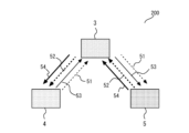
- First embodiment 4 is a diagram illustrating a configuration of a wireless communication system 200 according to embodiment 1.
- the wireless communication system 200 includes a first portable wireless station 4, a satellite 3, and a second portable wireless station 5.
- the first wireless station 4 transmits a first control signal 51 to the second wireless station 5 via the satellite 3.
- the first control signal 51 is also called a CSCO (Common Signaling Channel Outband) line.
- the first wireless station 4 also transmits a first communication signal 53 to the second wireless station 5.
- the second wireless station 5 transmits a second control signal 52 to the first wireless station 4 via the satellite 3.
- the second control signal 52 is also called a CSCI (Common Signaling Channel Inband) line.
- the second wireless station 5 also transmits a second communication signal 54 to the first wireless station 4.
- the second wireless station 5 determines whether the satellite 3 it has captured is the target satellite in a manner similar to that of the prior art. In other words, the second wireless station 5 is the ultra-small ground station described above.
- the first wireless station 4 determines whether the satellite 3 it has captured is the target satellite without relying on a control signal.
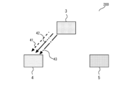
- FIG. 5 is a diagram explaining signals transmitted by satellite 3 according to the first embodiment.
- Satellite 3 transmits beacon signal 41, and telemetry signals 42 and 43 having mutually different frequencies to first wireless station 4.
- frequencies are assigned to beacon signal 41, telemetry signal 42, and telemetry signal 43 that are unique to satellite 3 or rarely overlap with those of other satellites.
- first wireless station 4 determines whether satellite 3 that it has captured is the target satellite.
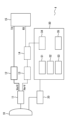
- FIG. 6 is a block diagram showing an example configuration of a first wireless station 4 according to the first embodiment.
- the first wireless station 4 has a configuration in which a DIV (Divider) 14, a measurement unit 34, and a memory unit 35 are added to the example configuration of the wireless station 1 of the prior art shown in FIG. 2.
- the DIV 14 distributes the received wave amplified by the LNB 13 into two or more.
- the measurement unit 34 receives the received wave distributed by the DIV 14 and measures the frequency and reception level.
- the memory unit 35 stores in advance the position information such as the longitude of the target satellite 3. In addition, the frequency of the beacon signal 41 and the telemetry signals 42 and 43 from the satellite 3 is stored in advance.
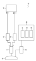
- FIG. 7 is a block diagram showing an example configuration of a second wireless station 5 according to the first embodiment.
- the example configuration of the second wireless station 5 is the same as the example configuration of the wireless station 1 shown in FIG. 2, so a description thereof will be omitted here.
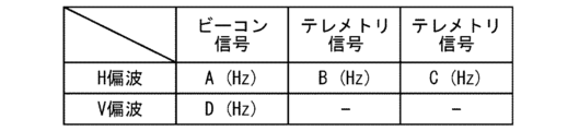
- FIG. 8 is an example of information stored in the memory unit 35 of the first wireless station 4 according to the first embodiment.
- the beacon signal 41 has two components, vertical and horizontal polarization. Therefore, the memory unit 35 stores the frequency of the beacon signal 41 of the target satellite 3 for each of the vertical and horizontal polarization.
- the telemetry signals 42 and 43 have only a horizontal polarization component. Therefore, the memory unit 35 stores the frequency of the telemetry signals 42 and 43 of the target satellite 3 for the horizontal polarization.
- the unit of frequency is, for example, Hz. Note that the frequencies of the beacon signal 41 and the telemetry signals 42 and 43 of the satellite 3 may not be a specific value, but may span a certain band. In this case, the memory unit 35 stores the frequency band of the beacon signal 41 and the telemetry signals 42 and 43.
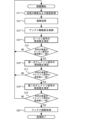
- FIG. 9 is a flowchart showing the processing executed by the first wireless station 4 according to the first embodiment.
- processing starts when the power is turned on.
- the orientation sensor 32 and the position sensor 33 acquire the latitude and longitude information of the station (step S11).
- the control unit 31 executes the calculation processing as in the comparative example (step S12). Note that the longitude information of the satellite 3 used in the calculation processing is provided from the memory unit 35.
- the control unit 31 controls the antenna driving unit 20 so that the antenna 10 is oriented in the calculated direction (step S13).
- the measurement unit 34 measures the frequency of the received beacon signal 41 (step S14). Furthermore, the control unit 31 checks whether the measured frequency matches the frequency of the beacon signal 41 of the target satellite 3 (step S15). As described above, the memory unit 35 stores the frequency of the beacon signal 41 of the target satellite 3 for both vertical and horizontal polarization. In checking the frequency match, it is checked whether the frequency of the beacon signal 41 of the target satellite 3 matches the frequency of the measured beacon signal 41 for the polarization used in the receiving system of the own station.
- the first wireless station 4 returns to the beginning of the process and performs recapture.
- the first radio station 4 checks the frequency of the telemetry signal 42.
- the measurement unit 34 measures the frequency of the received telemetry signal 42 (step S16). It then checks whether the measured frequency matches the frequency of the telemetry signal 42 of the target satellite 3 (step S17).
- the first wireless station 4 returns to the beginning of the process and performs recapture.
- the first radio station 4 checks the frequency based on the telemetry signal 43. That is, the measurement unit 34 measures the frequency of the received telemetry signal 43 (step S18). Furthermore, it is confirmed whether the measured frequency matches the frequency of the telemetry signal 43 of the target satellite 3 (step S19).
- the first wireless station 4 triple-checks whether the satellite 3 it has captured is the desired satellite, based on the frequencies of the three signals transmitted from the satellite 3. As described above, frequencies are assigned to the beacon signal 41 and the telemetry signals 42, 43 that are unique to the satellite 3, or that rarely overlap with those of other satellites. Therefore, it can be said that a satellite 3 whose frequencies are determined to match in each of the triple checks is highly likely to be the desired satellite.
- step S19 If a frequency match is confirmed in step S19, the first wireless station 4 identifies the captured satellite 3 as the target satellite. Furthermore, the control unit 31 controls the antenna driving unit 20 to perform the antenna adjustment process as in the comparative example (step S20). Finally, the process ends.
- step S14 may be executed only when the received power of the beacon signal 41 transmitted from the satellite 3 is equal to or greater than a predetermined threshold. This allows the frequency measurement to be stopped when the received power is too low, reducing the burden associated with inefficient measurements. Similarly, the frequency of the telemetry signals 42 and 43 may be measured only when the received power is equal to or greater than a threshold.
- the processing performed by the first wireless station 4 may be executed by a communication program using a computer equipped with a CPU and memory and storing a program in the memory.
- the processing may be executed by a communication program using an integrated circuit such as an FPGA (Field Programmable Gate Array).
- the communication program may be provided by being recorded on a storage medium, or may be provided via a network.
- the present disclosure provides a wireless communication system 200, a wireless station, a wireless communication method, and a wireless communication program that can identify whether a satellite that the station has captured is a target satellite without relying on a master station.
- the first wireless station 4 and the second wireless station 5 are portable wireless stations. However, the first wireless station 4 and the second wireless station 5 do not have to be portable stations. The above-mentioned effects can be obtained as long as the first wireless station 4 and the second wireless station 5 are wireless stations that are placed on the ground.
- the first wireless station 4 calculates the antenna direction for capturing the satellite 3 based on information on the latitude and longitude of the first wireless station 4 and the longitude of the satellite 3.
- the antenna direction does not necessarily have to be calculated based on the latitude and longitude, and may be calculated based on the position information of the first wireless station 4 and the position information of the satellite 3.
- the first wireless station 4 identifies whether the satellite it has captured is the target satellite based on the beacon signal 41 and the telemetry signals 42 and 43 transmitted by the satellite 3.
- the type of signal used is not limited to these. The above-mentioned effect can be obtained as long as the signal is not a signal that relays a signal transmitted from another wireless station, but is a unique signal transmitted by the satellite 3 itself, and is assigned a frequency that is unique to the satellite 3 or rarely overlaps with other satellites.
- the first wireless station 4 triple-checks whether the satellite 3 it has captured is the target satellite. However, if checking the frequencies of the two signals is sufficient to identify the satellite as the target satellite, the check may be doubled. In other words, it is sufficient to perform only one of the checks based on the telemetry signal 42 and the telemetry signal 43. This reduces the burden associated with the checks.
- the satellite 3 is referred to in the claims as the acquisition satellite.
- Radio station 2 Base station, 3 Satellite, 4 First radio station, 5 Second radio station, 10 Antenna, 11 OMT, 12 BUC, 13 LNB, 14 DIV, 15 MODEM 15, 20 Antenna driver, 21 Control signal, 30 Automatic capture controller, 31 Controller, 32 Orientation sensor, 33 Position sensor, 34 Measurement unit, 35 Memory unit, 41 Beacon signal, 42, 43 Telemetry signal, 51 First control signal, 52 Second control signal, 53 First communication signal, 54 Second communication signal, 100 Conventional wireless communication system, 200 Wireless communication system
Landscapes
- Engineering & Computer Science (AREA)
- Physics & Mathematics (AREA)
- Astronomy & Astrophysics (AREA)
- Aviation & Aerospace Engineering (AREA)
- General Physics & Mathematics (AREA)
- Computer Networks & Wireless Communication (AREA)
- Signal Processing (AREA)
- Radio Relay Systems (AREA)
Abstract
La présente invention concerne un système de communication sans fil et a pour objectif de fournir un système de communication sans fil capable d'identifier si un satellite acquis par le système de communication sans fil lui-même est un satellite cible sans dépendre d'une station maîtresse. Le système de communication sans fil selon la présente invention comprend : une première station radio (4) utilisée au sol ; et un satellite (3). La première station radio (4) calcule la direction d'une antenne pour l'acquisition d'un satellite cible sur la base des informations de position de la station et des informations de position du satellite cible. En outre, l'antenne est orientée dans la direction calculée, et un premier signal unique et un second signal unique émis par le satellite (3) lui-même sont reçus du satellite (3). En outre, la fréquence est mesurée pour chacun du premier signal unique et du second signal unique provenant du satellite (3). En outre, il est confirmé que les fréquences du premier signal unique et du second signal unique du satellite (3) correspondent respectivement aux fréquences d'un premier signal unique et d'un second signal unique du satellite cible. Lorsqu'une correspondance est confirmée pour les deux ensembles de signaux, le satellite (3) est identifié comme étant le satellite cible.
Priority Applications (2)
| Application Number | Priority Date | Filing Date | Title |
|---|---|---|---|
| JP2025525465A JPWO2024252489A1 (fr) | 2023-06-05 | 2023-06-05 | |
| PCT/JP2023/020865 WO2024252489A1 (fr) | 2023-06-05 | 2023-06-05 | Système de communication sans fil, station radio, procédé de communication sans fil et programme de communication sans fil |
Applications Claiming Priority (1)
| Application Number | Priority Date | Filing Date | Title |
|---|---|---|---|
| PCT/JP2023/020865 WO2024252489A1 (fr) | 2023-06-05 | 2023-06-05 | Système de communication sans fil, station radio, procédé de communication sans fil et programme de communication sans fil |
Publications (1)
| Publication Number | Publication Date |
|---|---|
| WO2024252489A1 true WO2024252489A1 (fr) | 2024-12-12 |
Family
ID=93795126
Family Applications (1)
| Application Number | Title | Priority Date | Filing Date |
|---|---|---|---|
| PCT/JP2023/020865 Ceased WO2024252489A1 (fr) | 2023-06-05 | 2023-06-05 | Système de communication sans fil, station radio, procédé de communication sans fil et programme de communication sans fil |
Country Status (2)
| Country | Link |
|---|---|
| JP (1) | JPWO2024252489A1 (fr) |
| WO (1) | WO2024252489A1 (fr) |
Citations (4)
| Publication number | Priority date | Publication date | Assignee | Title |
|---|---|---|---|---|
| JPH1120800A (ja) * | 1997-07-01 | 1999-01-26 | Nec Corp | 衛星捕捉・追尾装置 |
| JPH11264863A (ja) * | 1998-03-17 | 1999-09-28 | Nec Corp | 衛星追尾方式と衛星通信システム |
| JP2016118447A (ja) * | 2014-12-19 | 2016-06-30 | 三菱電機株式会社 | ゲートウェイ、通信端末および衛星通信システム |
| WO2021250821A1 (fr) * | 2020-06-10 | 2021-12-16 | 日本電信電話株式会社 | Procédé de réglage de direction d'antenne, dispositif de station portable et programme de réglage de direction d'antenne dans un système de communication par satellite |
-
2023
- 2023-06-05 JP JP2025525465A patent/JPWO2024252489A1/ja active Pending
- 2023-06-05 WO PCT/JP2023/020865 patent/WO2024252489A1/fr not_active Ceased
Patent Citations (4)
| Publication number | Priority date | Publication date | Assignee | Title |
|---|---|---|---|---|
| JPH1120800A (ja) * | 1997-07-01 | 1999-01-26 | Nec Corp | 衛星捕捉・追尾装置 |
| JPH11264863A (ja) * | 1998-03-17 | 1999-09-28 | Nec Corp | 衛星追尾方式と衛星通信システム |
| JP2016118447A (ja) * | 2014-12-19 | 2016-06-30 | 三菱電機株式会社 | ゲートウェイ、通信端末および衛星通信システム |
| WO2021250821A1 (fr) * | 2020-06-10 | 2021-12-16 | 日本電信電話株式会社 | Procédé de réglage de direction d'antenne, dispositif de station portable et programme de réglage de direction d'antenne dans un système de communication par satellite |
Also Published As
| Publication number | Publication date |
|---|---|
| JPWO2024252489A1 (fr) | 2024-12-12 |
Similar Documents
| Publication | Publication Date | Title |
|---|---|---|
| JP2979582B2 (ja) | 伝送システム | |
| RU2213980C2 (ru) | Устройство радиосвязи и система, включающая в себя средство определения местонахождения | |
| US7039421B2 (en) | System for determining the position of an object | |
| EP2784533B1 (fr) | Procédé et dispositif d'acquisition d'informations concernant une antenne de station de base, et antenne de station de base | |
| JP3479885B2 (ja) | 移動端末を用いた測位方法及び測位機能を有する移動端末 | |
| US20010020912A1 (en) | GPS receiver and portable communication apparatus | |
| US20230115735A1 (en) | Antenna direction adjusting method, portable station device and antenna direction adjusting program in satellite communication system | |
| CA2367032A1 (fr) | Procede et appareil de mesure du temps destines a un systeme de positionnement par satellite (sps) | |
| JP2002532679A5 (fr) | ||
| US20130203437A1 (en) | Cells obtaining timing and positioning by using satellite systems with high power signals for improved building penetration | |
| US20190004182A1 (en) | Gnss antenna with an integrated antenna element and additional information sources | |
| JP2001343447A (ja) | 移動体位置検出方法 | |
| WO2003005055A1 (fr) | Recepteur gps et procede de determination d'une position d'un terminal sans fil | |
| JP7435769B2 (ja) | 衛星通信システムにおけるアンテナ方向調整方法、可搬局装置およびアンテナ方向調整プログラム | |
| JP7287576B2 (ja) | 衛星通信システムにおける送信電波確認方法、可搬局装置および送信電波確認プログラム | |
| KR20040070847A (ko) | 의사위성을 이용한 자동 식별 시스템 및 자동 식별 방법 | |
| US20070194985A1 (en) | Method for the accelerated acquisition of satellite signals | |
| CN119544006A (zh) | 对星方法、终端设备和计算机可读存储介质 | |
| JP2001119333A (ja) | 移動体通信システムおよびドップラーシフト補正通信方法 | |
| JPH1123686A (ja) | 衛星追尾装置 | |
| JPH09233564A (ja) | 遠隔操縦用アンテナ制御システム | |
| JPS63153925A (ja) | 空中線姿勢制御装置 | |
| US8121095B2 (en) | System and method for adjusting a time offset of GPS signals in a CDMA mobile phone | |
| JP3067730B2 (ja) | 衛星追尾方式と衛星通信システム | |
| JP3732151B2 (ja) | 車載中継局の衛星捕捉システム及び車載中継局の衛星捕捉方法 |
Legal Events
| Date | Code | Title | Description |
|---|---|---|---|
| 121 | Ep: the epo has been informed by wipo that ep was designated in this application |
Ref document number: 23940596 Country of ref document: EP Kind code of ref document: A1 |
|
| ENP | Entry into the national phase |
Ref document number: 2025525465 Country of ref document: JP Kind code of ref document: A |
|
| NENP | Non-entry into the national phase |
Ref country code: DE |