WO2024252489A1 - 無線通信システム、無線局、無線通信方法、および無線通信用プログラム - Google Patents
無線通信システム、無線局、無線通信方法、および無線通信用プログラム Download PDFInfo
- Publication number
- WO2024252489A1 WO2024252489A1 PCT/JP2023/020865 JP2023020865W WO2024252489A1 WO 2024252489 A1 WO2024252489 A1 WO 2024252489A1 JP 2023020865 W JP2023020865 W JP 2023020865W WO 2024252489 A1 WO2024252489 A1 WO 2024252489A1
- Authority
- WO
- WIPO (PCT)
- Prior art keywords
- satellite
- signal
- frequencies
- station
- captured
- Prior art date
- Legal status (The legal status is an assumption and is not a legal conclusion. Google has not performed a legal analysis and makes no representation as to the accuracy of the status listed.)
- Ceased
Links
Images


Classifications
-
- H—ELECTRICITY
- H04—ELECTRIC COMMUNICATION TECHNIQUE
- H04B—TRANSMISSION
- H04B7/00—Radio transmission systems, i.e. using radiation field
- H04B7/14—Relay systems
- H04B7/15—Active relay systems
- H04B7/185—Space-based or airborne stations; Stations for satellite systems
Definitions
- the present disclosure relates to a wireless communication system, a wireless communication device, a wireless communication method, and a wireless communication program.
- the present disclosure relates to a technique for identifying whether a satellite captured by a radio station located on the ground is a target satellite.
- Patent Document 1 discloses a technology for capturing a satellite at a radio station located on the ground.
- the radio station determines whether the satellite it has captured is the target satellite based on a control signal transmitted to the radio station from the parent base station via the satellite.
- the wireless station cannot determine whether the satellite it has captured is the desired satellite.
- the first objective of this disclosure is to provide a wireless communication system that can identify whether a satellite it has captured is the desired satellite without relying on a master station.
- a second object of this disclosure is to provide a wireless station that can determine whether a satellite it has captured is the desired satellite without relying on a master station.
- a third object of this disclosure is to provide a wireless communication method that can identify whether a satellite that has been captured by the device is the desired satellite without relying on a master station.
- the second aspect is A radio station for use on land, A process of calculating an antenna direction for capturing a target satellite based on position information of the own station and position information of the target satellite; A process of receiving a first unique signal and a second unique signal emitted by a capture satellite captured by pointing an antenna in the direction; a measurement process for measuring a frequency of each of the first and second unique signals of the captured satellite; a confirmation process for confirming whether the frequencies of the first and second specific signals of the acquisition satellite match the frequencies of the first and second specific signals of the target satellite, respectively; a process of identifying the captured satellite as the target satellite when a match between the frequencies of the first specific signal and the second specific signal is confirmed;
- the method is configured to execute:
- the third aspect is Radio stations used on the ground: Calculating an antenna direction for capturing a target satellite based on position information of the own station and position information of the target satellite; receiving a first unique signal and a second unique signal emitted by a capture satellite captured by pointing an antenna in the direction; measuring a frequency of each of the first and second unique signals of the acquired satellite; determining whether the frequencies of the first and second unique signals of the acquisition satellite match the frequencies of the first and second unique signals of the target satellite, respectively; Identifying the captured satellite as the target satellite when a match between the frequencies of the first specific signal and the second specific signal is confirmed;
- the wireless communication method includes:
- the fourth aspect is A radio communication program to be executed by a radio station used on the ground, To the radio station, A process of calculating an antenna direction for capturing a target satellite based on position information of the own station and position information of the target satellite; A process of receiving a first unique signal and a second unique signal emitted by a capture satellite captured by pointing an antenna in the direction; a measurement process for measuring a frequency of each of the first and second unique signals of the captured satellite; a confirmation process for confirming whether the frequencies of the first and second specific signals of the acquisition satellite match the frequencies of the first and second specific signals of the target satellite, respectively; a process of identifying the captured satellite as the target satellite when a match between the frequencies of the first specific signal and the second specific signal is confirmed; It is preferable that the program includes a program for executing the above.
- the first to fourth aspects of the present disclosure provide a wireless communication system, a wireless communication device, a wireless communication method, and a wireless communication program that can identify whether a satellite that has been captured by the system is a target satellite without relying on a parent station.
- FIG. 1 is a diagram showing a configuration of a conventional wireless communication system according to a comparative example of the present disclosure.
- FIG. 2 is a block diagram showing an example configuration of a wireless station in the prior art according to a comparative example of the present disclosure.
- 1 is a flowchart showing a process executed by a wireless station in the prior art according to a comparative example of the present disclosure.
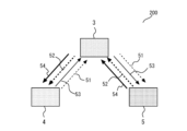
- 1 is a diagram illustrating a configuration of a wireless communication system according to a first embodiment.
- 3 is a diagram for explaining a signal transmitted by a satellite in the first embodiment;
- FIG. FIG. 2 is a block diagram showing a configuration example of a first wireless station according to the first embodiment;
- 2 is a block diagram showing a configuration example of a second wireless station according to the first embodiment
- 5 is an example of information stored in a storage unit of a first wireless station according to the first embodiment.
- 5 is a flowchart showing a process executed by a first wireless station according to the first embodiment
- FIG. 1 is a diagram showing a configuration of a conventional wireless communication system 100 according to a comparative example of the present disclosure.
- the conventional wireless communication system 100 includes a wireless station 1, a base station 2 as a master station, and a satellite 3.
- the radio station 1 is a portable radio station used on the ground.
- the radio station 1 is a so-called very small earth station (VSAT) that communicates with the parent station via the satellite 3.
- VSAT very small earth station
- the radio station 1 executes a calculation process to calculate the antenna direction for capturing the satellite 3 based on the latitude and longitude of the radio station itself and the longitude of the satellite 3. It then aims the antenna in the calculated direction and attempts to receive the beacon signal 41 transmitted from the satellite 3. It also executes an antenna adjustment process to adjust the antenna angle so that the reception strength of the beacon signal 41 is maximized. In the antenna angle adjustment, the antenna is adjusted in three directions: azimuth, elevation, and polarization angle.
- the beacon signal 41 is an unmodulated wave (clean wave, hereafter referred to as CW) at a specific frequency.
- FIG. 2 is a block diagram showing an example configuration of a wireless station 1 in the prior art, which is a comparative example of the present disclosure.
- a configuration example is shown in which vertical polarization is used in the transmission system and horizontal polarization is used in the reception system.
- the direction of polarization is the direction of rotation of the polarization plane when viewed from a direction directly facing the direction of travel of the radio waves.
- Antenna 10 transmits and receives radio waves.
- OMT Organic Mode Transducer
- BUC Block Up Converter
- LNB Low Noise Block Converter
- the MODEM 15 modulates the transmission signal and demodulates the reception signal.
- the antenna driver 20 adjusts the angle of the antenna 10.
- the automatic capture control unit 30 executes the above-mentioned calculation processing and antenna adjustment processing.
- the automatic capture control unit 30 includes a control unit 31, a direction sensor 32, and a position sensor 33.
- FIG. 3 is a flowchart showing the process executed by the wireless station 1 in the prior art, which is a comparative example of the present disclosure.
- the process starts when the power is turned on.
- the orientation sensor 32 and the position sensor 33 acquire the latitude and longitude information of the station (step S01).
- a GPS Global Positioning System
- the control unit 31 executes the above-mentioned calculation process (step S02).
- the antenna direction for capturing the satellite 3 is calculated by displaying the azimuth angle, elevation angle, and polarization angle.
- the control unit 31 controls the antenna driving unit 20 so that the antenna 10 faces the calculated direction (step S03).
- the control unit 31 controls the antenna driving unit 20 to execute the above-mentioned antenna adjustment process (step S04).
- the MODEM 15 checks whether or not it is synchronized with the received control signal 21 (step S05). If synchronization is confirmed, this means that the satellite it has captured is the target satellite. Therefore, the wireless station 1 identifies the satellite 3 it has captured as the target satellite. Finally, the process ends.
- wireless station 1 returns to the beginning of the process and attempts to recapture the satellite.
- wireless station 1 cannot determine whether the satellite it has captured is the desired satellite without a master station responsible for transmitting control signals 21.
- First embodiment 4 is a diagram illustrating a configuration of a wireless communication system 200 according to embodiment 1.
- the wireless communication system 200 includes a first portable wireless station 4, a satellite 3, and a second portable wireless station 5.
- the first wireless station 4 transmits a first control signal 51 to the second wireless station 5 via the satellite 3.
- the first control signal 51 is also called a CSCO (Common Signaling Channel Outband) line.
- the first wireless station 4 also transmits a first communication signal 53 to the second wireless station 5.
- the second wireless station 5 transmits a second control signal 52 to the first wireless station 4 via the satellite 3.
- the second control signal 52 is also called a CSCI (Common Signaling Channel Inband) line.
- the second wireless station 5 also transmits a second communication signal 54 to the first wireless station 4.
- the second wireless station 5 determines whether the satellite 3 it has captured is the target satellite in a manner similar to that of the prior art. In other words, the second wireless station 5 is the ultra-small ground station described above.
- the first wireless station 4 determines whether the satellite 3 it has captured is the target satellite without relying on a control signal.
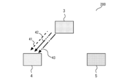
- FIG. 5 is a diagram explaining signals transmitted by satellite 3 according to the first embodiment.
- Satellite 3 transmits beacon signal 41, and telemetry signals 42 and 43 having mutually different frequencies to first wireless station 4.
- frequencies are assigned to beacon signal 41, telemetry signal 42, and telemetry signal 43 that are unique to satellite 3 or rarely overlap with those of other satellites.
- first wireless station 4 determines whether satellite 3 that it has captured is the target satellite.
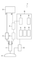
- FIG. 6 is a block diagram showing an example configuration of a first wireless station 4 according to the first embodiment.
- the first wireless station 4 has a configuration in which a DIV (Divider) 14, a measurement unit 34, and a memory unit 35 are added to the example configuration of the wireless station 1 of the prior art shown in FIG. 2.
- the DIV 14 distributes the received wave amplified by the LNB 13 into two or more.
- the measurement unit 34 receives the received wave distributed by the DIV 14 and measures the frequency and reception level.
- the memory unit 35 stores in advance the position information such as the longitude of the target satellite 3. In addition, the frequency of the beacon signal 41 and the telemetry signals 42 and 43 from the satellite 3 is stored in advance.
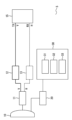
- FIG. 7 is a block diagram showing an example configuration of a second wireless station 5 according to the first embodiment.
- the example configuration of the second wireless station 5 is the same as the example configuration of the wireless station 1 shown in FIG. 2, so a description thereof will be omitted here.
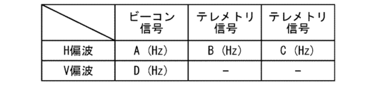
- FIG. 8 is an example of information stored in the memory unit 35 of the first wireless station 4 according to the first embodiment.
- the beacon signal 41 has two components, vertical and horizontal polarization. Therefore, the memory unit 35 stores the frequency of the beacon signal 41 of the target satellite 3 for each of the vertical and horizontal polarization.
- the telemetry signals 42 and 43 have only a horizontal polarization component. Therefore, the memory unit 35 stores the frequency of the telemetry signals 42 and 43 of the target satellite 3 for the horizontal polarization.
- the unit of frequency is, for example, Hz. Note that the frequencies of the beacon signal 41 and the telemetry signals 42 and 43 of the satellite 3 may not be a specific value, but may span a certain band. In this case, the memory unit 35 stores the frequency band of the beacon signal 41 and the telemetry signals 42 and 43.
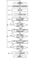
- FIG. 9 is a flowchart showing the processing executed by the first wireless station 4 according to the first embodiment.
- processing starts when the power is turned on.
- the orientation sensor 32 and the position sensor 33 acquire the latitude and longitude information of the station (step S11).
- the control unit 31 executes the calculation processing as in the comparative example (step S12). Note that the longitude information of the satellite 3 used in the calculation processing is provided from the memory unit 35.
- the control unit 31 controls the antenna driving unit 20 so that the antenna 10 is oriented in the calculated direction (step S13).
- the measurement unit 34 measures the frequency of the received beacon signal 41 (step S14). Furthermore, the control unit 31 checks whether the measured frequency matches the frequency of the beacon signal 41 of the target satellite 3 (step S15). As described above, the memory unit 35 stores the frequency of the beacon signal 41 of the target satellite 3 for both vertical and horizontal polarization. In checking the frequency match, it is checked whether the frequency of the beacon signal 41 of the target satellite 3 matches the frequency of the measured beacon signal 41 for the polarization used in the receiving system of the own station.
- the first wireless station 4 returns to the beginning of the process and performs recapture.
- the first radio station 4 checks the frequency of the telemetry signal 42.
- the measurement unit 34 measures the frequency of the received telemetry signal 42 (step S16). It then checks whether the measured frequency matches the frequency of the telemetry signal 42 of the target satellite 3 (step S17).
- the first wireless station 4 returns to the beginning of the process and performs recapture.
- the first radio station 4 checks the frequency based on the telemetry signal 43. That is, the measurement unit 34 measures the frequency of the received telemetry signal 43 (step S18). Furthermore, it is confirmed whether the measured frequency matches the frequency of the telemetry signal 43 of the target satellite 3 (step S19).
- the first wireless station 4 triple-checks whether the satellite 3 it has captured is the desired satellite, based on the frequencies of the three signals transmitted from the satellite 3. As described above, frequencies are assigned to the beacon signal 41 and the telemetry signals 42, 43 that are unique to the satellite 3, or that rarely overlap with those of other satellites. Therefore, it can be said that a satellite 3 whose frequencies are determined to match in each of the triple checks is highly likely to be the desired satellite.
- step S19 If a frequency match is confirmed in step S19, the first wireless station 4 identifies the captured satellite 3 as the target satellite. Furthermore, the control unit 31 controls the antenna driving unit 20 to perform the antenna adjustment process as in the comparative example (step S20). Finally, the process ends.
- step S14 may be executed only when the received power of the beacon signal 41 transmitted from the satellite 3 is equal to or greater than a predetermined threshold. This allows the frequency measurement to be stopped when the received power is too low, reducing the burden associated with inefficient measurements. Similarly, the frequency of the telemetry signals 42 and 43 may be measured only when the received power is equal to or greater than a threshold.
- the processing performed by the first wireless station 4 may be executed by a communication program using a computer equipped with a CPU and memory and storing a program in the memory.
- the processing may be executed by a communication program using an integrated circuit such as an FPGA (Field Programmable Gate Array).
- the communication program may be provided by being recorded on a storage medium, or may be provided via a network.
- the present disclosure provides a wireless communication system 200, a wireless station, a wireless communication method, and a wireless communication program that can identify whether a satellite that the station has captured is a target satellite without relying on a master station.
- the first wireless station 4 and the second wireless station 5 are portable wireless stations. However, the first wireless station 4 and the second wireless station 5 do not have to be portable stations. The above-mentioned effects can be obtained as long as the first wireless station 4 and the second wireless station 5 are wireless stations that are placed on the ground.
- the first wireless station 4 calculates the antenna direction for capturing the satellite 3 based on information on the latitude and longitude of the first wireless station 4 and the longitude of the satellite 3.
- the antenna direction does not necessarily have to be calculated based on the latitude and longitude, and may be calculated based on the position information of the first wireless station 4 and the position information of the satellite 3.
- the first wireless station 4 identifies whether the satellite it has captured is the target satellite based on the beacon signal 41 and the telemetry signals 42 and 43 transmitted by the satellite 3.
- the type of signal used is not limited to these. The above-mentioned effect can be obtained as long as the signal is not a signal that relays a signal transmitted from another wireless station, but is a unique signal transmitted by the satellite 3 itself, and is assigned a frequency that is unique to the satellite 3 or rarely overlaps with other satellites.
- the first wireless station 4 triple-checks whether the satellite 3 it has captured is the target satellite. However, if checking the frequencies of the two signals is sufficient to identify the satellite as the target satellite, the check may be doubled. In other words, it is sufficient to perform only one of the checks based on the telemetry signal 42 and the telemetry signal 43. This reduces the burden associated with the checks.
- the satellite 3 is referred to in the claims as the acquisition satellite.
- Radio station 2 Base station, 3 Satellite, 4 First radio station, 5 Second radio station, 10 Antenna, 11 OMT, 12 BUC, 13 LNB, 14 DIV, 15 MODEM 15, 20 Antenna driver, 21 Control signal, 30 Automatic capture controller, 31 Controller, 32 Orientation sensor, 33 Position sensor, 34 Measurement unit, 35 Memory unit, 41 Beacon signal, 42, 43 Telemetry signal, 51 First control signal, 52 Second control signal, 53 First communication signal, 54 Second communication signal, 100 Conventional wireless communication system, 200 Wireless communication system
Landscapes
- Engineering & Computer Science (AREA)
- Physics & Mathematics (AREA)
- Astronomy & Astrophysics (AREA)
- Aviation & Aerospace Engineering (AREA)
- General Physics & Mathematics (AREA)
- Computer Networks & Wireless Communication (AREA)
- Signal Processing (AREA)
- Radio Relay Systems (AREA)
Abstract
本開示は無線通信システムに関し、自己が捕捉した衛星が目的の衛星であるかを親局に頼ることなく特定できる無線通信システムを提供することを目的とする。本開示の無線通信システムは、地上で用いられる第一の無線局4と、衛星3とを備える。第一の無線局4は、自局の位置情報、および目的の衛星の位置情報に基づき、目的の衛星を捕捉するためのアンテナの方向を演算する。さらに、演算された方向にアンテナを向け、衛星3から、衛星3が自ら発する第一の固有信号および第二の固有信号を受信する。さらに、衛星3の第一の固有信号および第二の固有信号のそれぞれについて周波数を測定する。さらに、衛星3の第一の固有信号および第二の固有信号の周波数が、目的の衛星の第一の固有信号および第二の固有信号の周波数にそれぞれ一致するかを確認する。それぞれの一致が確認できた場合に、衛星3が目的の衛星であると特定する。
Description
本開示は、無線通信システム、無線通信装置、無線通信方法、および無線通信用プログラムに関する。特に地上に配置された無線局によって捕捉された衛星が目的の衛星であるかを特定するための技術に関する。
特許文献1には、地上に配置された無線局において、衛星を捕捉する技術が開示されている。無線局は、親局である基地局から衛星を介して無線局に送信される制御信号に基づき、自己が捕捉した衛星が目的の衛星であるかを特定する。
しかしながら上述の方法では、親局が無い場合には、無線局は自己が捕捉した衛星が目的の衛星であるかを特定できない。
本開示は上述の課題を解決するため、自己が捕捉した衛星が目的の衛星であるかを親局に頼ることなく特定できる無線通信システムを提供することを第一の目的とする。
また本開示は、自己が捕捉した衛星が目的の衛星であるかを親局に頼ることなく特定できる無線局を提供することを第二の目的とする。
また本開示は、自己が捕捉した衛星が目的の衛星であるかを親局に頼ることなく特定できる無線通信方法を提供することを第三の目的とする。
また本開示は、自己が捕捉した衛星が目的の衛星であるかを親局に頼ることなく特定できる無線通信用プログラムを提供することを第四の目的とする。
本開示の第一の態様は、
地上で用いられる第一の無線局と、
前記第一の無線局に捕捉される捕捉衛星と、
を備え、
前記第一の無線局は、
自局の位置情報、および目的の衛星の位置情報に基づき、前記目的の衛星を捕捉するためのアンテナの方向を演算する処理と、
前記方向にアンテナを向け、前記捕捉衛星から、前記捕捉衛星が自ら発する第一の固有信号および第二の固有信号を受信する処理と、
前記捕捉衛星の前記第一の固有信号および前記第二の固有信号のそれぞれについて周波数を測定する測定処理と、
前記捕捉衛星の前記第一の固有信号および前記第二の固有信号の周波数が、前記目的の衛星の前記第一の固有信号および前記第二の固有信号の周波数にそれぞれ一致するかを確認する確認処理と、
前記第一の固有信号および前記第二の固有信号のそれぞれにつき周波数の一致が確認できた場合に、前記捕捉衛星が前記目的の衛星であると特定する処理と、
を実行するように構成される無線通信システムであることが好ましい。
地上で用いられる第一の無線局と、
前記第一の無線局に捕捉される捕捉衛星と、
を備え、
前記第一の無線局は、
自局の位置情報、および目的の衛星の位置情報に基づき、前記目的の衛星を捕捉するためのアンテナの方向を演算する処理と、
前記方向にアンテナを向け、前記捕捉衛星から、前記捕捉衛星が自ら発する第一の固有信号および第二の固有信号を受信する処理と、
前記捕捉衛星の前記第一の固有信号および前記第二の固有信号のそれぞれについて周波数を測定する測定処理と、
前記捕捉衛星の前記第一の固有信号および前記第二の固有信号の周波数が、前記目的の衛星の前記第一の固有信号および前記第二の固有信号の周波数にそれぞれ一致するかを確認する確認処理と、
前記第一の固有信号および前記第二の固有信号のそれぞれにつき周波数の一致が確認できた場合に、前記捕捉衛星が前記目的の衛星であると特定する処理と、
を実行するように構成される無線通信システムであることが好ましい。
また、第二の態様は、
地上で用いられる無線局であって、
自局の位置情報、および目的の衛星の位置情報に基づき、前記目的の衛星を捕捉するためのアンテナの方向を演算する処理と、
前記方向にアンテナを向け捕捉した捕捉衛星から、前記捕捉衛星が自ら発する第一の固有信号および第二の固有信号を受信する処理と、
前記捕捉衛星の前記第一の固有信号および前記第二の固有信号のそれぞれについて周波数を測定する測定処理と、
前記捕捉衛星の前記第一の固有信号および前記第二の固有信号の周波数が、前記目的の衛星の前記第一の固有信号および前記第二の固有信号の周波数にそれぞれ一致するかを確認する確認処理と、
前記第一の固有信号および前記第二の固有信号のそれぞれにつき周波数の一致が確認できた場合に、前記捕捉衛星が前記目的の衛星であると特定する処理と、
を実行するように構成されることが好ましい。
地上で用いられる無線局であって、
自局の位置情報、および目的の衛星の位置情報に基づき、前記目的の衛星を捕捉するためのアンテナの方向を演算する処理と、
前記方向にアンテナを向け捕捉した捕捉衛星から、前記捕捉衛星が自ら発する第一の固有信号および第二の固有信号を受信する処理と、
前記捕捉衛星の前記第一の固有信号および前記第二の固有信号のそれぞれについて周波数を測定する測定処理と、
前記捕捉衛星の前記第一の固有信号および前記第二の固有信号の周波数が、前記目的の衛星の前記第一の固有信号および前記第二の固有信号の周波数にそれぞれ一致するかを確認する確認処理と、
前記第一の固有信号および前記第二の固有信号のそれぞれにつき周波数の一致が確認できた場合に、前記捕捉衛星が前記目的の衛星であると特定する処理と、
を実行するように構成されることが好ましい。
また、第三の態様は、
地上で用いられる無線局が、
自局の位置情報、および目的の衛星の位置情報に基づき、前記目的の衛星を捕捉するためのアンテナの方向を演算することと、
前記方向にアンテナを向け捕捉した捕捉衛星から、前記捕捉衛星が自ら発する第一の固有信号および第二の固有信号を受信することと、
前記捕捉衛星の前記第一の固有信号および前記第二の固有信号のそれぞれについて周波数を測定することと、
前記捕捉衛星の前記第一の固有信号および前記第二の固有信号の周波数が、前記目的の衛星の前記第一の固有信号および前記第二の固有信号の周波数にそれぞれ一致するかを確認することと、
前記第一の固有信号および前記第二の固有信号のそれぞれにつき周波数の一致が確認できた場合に、前記捕捉衛星が前記目的の衛星であると特定することと、
を含む、無線通信方法であることが好ましい。
地上で用いられる無線局が、
自局の位置情報、および目的の衛星の位置情報に基づき、前記目的の衛星を捕捉するためのアンテナの方向を演算することと、
前記方向にアンテナを向け捕捉した捕捉衛星から、前記捕捉衛星が自ら発する第一の固有信号および第二の固有信号を受信することと、
前記捕捉衛星の前記第一の固有信号および前記第二の固有信号のそれぞれについて周波数を測定することと、
前記捕捉衛星の前記第一の固有信号および前記第二の固有信号の周波数が、前記目的の衛星の前記第一の固有信号および前記第二の固有信号の周波数にそれぞれ一致するかを確認することと、
前記第一の固有信号および前記第二の固有信号のそれぞれにつき周波数の一致が確認できた場合に、前記捕捉衛星が前記目的の衛星であると特定することと、
を含む、無線通信方法であることが好ましい。
また、第四の態様は、
地上で用いられる無線局に実行させる無線通信用プログラムであって、
無線局に、
自局の位置情報、および目的の衛星の位置情報に基づき、前記目的の衛星を捕捉するためのアンテナの方向を演算する処理と、
前記方向にアンテナを向け捕捉した捕捉衛星から、前記捕捉衛星が自ら発する第一の固有信号および第二の固有信号を受信する処理と、
前記捕捉衛星の前記第一の固有信号および前記第二の固有信号のそれぞれについて周波数を測定する測定処理と、
前記捕捉衛星の前記第一の固有信号および前記第二の固有信号の周波数が、前記目的の衛星の前記第一の固有信号および前記第二の固有信号の周波数にそれぞれ一致するかを確認する確認処理と、
前記第一の固有信号および前記第二の固有信号のそれぞれにつき周波数の一致が確認できた場合に、前記捕捉衛星が前記目的の衛星であると特定する処理と、
を実行させるプログラムを含むことが好ましい。
地上で用いられる無線局に実行させる無線通信用プログラムであって、
無線局に、
自局の位置情報、および目的の衛星の位置情報に基づき、前記目的の衛星を捕捉するためのアンテナの方向を演算する処理と、
前記方向にアンテナを向け捕捉した捕捉衛星から、前記捕捉衛星が自ら発する第一の固有信号および第二の固有信号を受信する処理と、
前記捕捉衛星の前記第一の固有信号および前記第二の固有信号のそれぞれについて周波数を測定する測定処理と、
前記捕捉衛星の前記第一の固有信号および前記第二の固有信号の周波数が、前記目的の衛星の前記第一の固有信号および前記第二の固有信号の周波数にそれぞれ一致するかを確認する確認処理と、
前記第一の固有信号および前記第二の固有信号のそれぞれにつき周波数の一致が確認できた場合に、前記捕捉衛星が前記目的の衛星であると特定する処理と、
を実行させるプログラムを含むことが好ましい。
本開示の第一から第四の態様によれば、自己が捕捉した衛星が目的の衛星であるかを親局に頼ることなく特定できる無線通信システム、無線通信装置、無線通信方法、および無線通信用プログラムを提供できる。
比較例
ここではまず、本開示の比較例として、従来技術の無線局1が、自己が捕捉した衛星が目的の衛星であるかを特定する方法を説明する。図1は、本開示の比較例に係る、従来の無線通信システム100の構成を示す図である。従来の無線通信システム100は、無線局1、親局としての基地局2、および衛星3を備える。
ここではまず、本開示の比較例として、従来技術の無線局1が、自己が捕捉した衛星が目的の衛星であるかを特定する方法を説明する。図1は、本開示の比較例に係る、従来の無線通信システム100の構成を示す図である。従来の無線通信システム100は、無線局1、親局としての基地局2、および衛星3を備える。
無線局1は地上で用いられる、可搬型の無線局である。無線局1は、親局と衛星3を介して通信する、いわゆる超小型地球局(Very Small Aperture Terminal、VSAT)である。無線局1は、自局の緯度、経度、および衛星3の経度の情報に基づき、衛星3を捕捉するためのアンテナ方向を演算する演算処理を実行する。さらに、演算した方向に対して、アンテナを向け、衛星3から発信されるビーコン信号41の受信を試みる。さらに、ビーコン信号41の受信強度が最大となるように、アンテナ角度を調整するアンテナ調整処理を実行する。アンテナ角度調整においては、方位角、仰角、偏波角の3方向に対してアンテナを調整する。なお、ビーコン信号41は、特定の周波数における無変調波(Clean Wave、以下、CWと称する)である。
さらに、無線局1は、基地局2からの制御信号21を、衛星3を介して受信する。制御信号21は、基地局2から衛星3に対して常に送信されているものである。無線局1は、受信した制御信号21に同期することを確認する。これにより、無線局1は、自己が捕捉した衛星が、目的の衛星であると確認することができる。
図2は、本開示の比較例に係る、先行技術における無線局1の構成例を示すブロック図である。ここでは、送信系には垂直偏波が用いられ、受信系には水平偏波が用いられる場合の構成例を示す。なお、偏波の方向は、電波の進行方向に正対する方向からみた場合の、偏波面の回転方向である。
アンテナ10は、無線電波を送受信する。OMT(Ortho Mode Transducer)11は、送信波または受信波における直交二偏波を分離する。BUC(Block Up Converter)12は、衛星3向けに周波数変換を行い電波の増幅を行う。LNB(Low Noise Block converter)13は、衛星3からの微弱な電波を受け取り増幅する。
MODEM15は、送信信号の変調、および受信信号の復調を行なう。アンテナ駆動部20は、アンテナ10の角度調整を行う。自動捕捉制御部30は、上述の演算処理、およびアンテナ調整処理を実行する。自動捕捉制御部30は、制御部31、方位センサ32、および位置センサ33を備える。
図3は、本開示の比較例に係る、先行技術における無線局1が実行する処理を示すフローチャートである。まず、電源が投入されるに伴い、処理を開始する。つぎに、方位センサ32および位置センサ33が、自局の緯度および経度情報を取得する(ステップS01)。経度および緯度情報の取得には、GPS(Global Positioning System)等が用いられる。さらに、制御部31が、上述の演算処理を実行する(ステップS02)。演算処理においては、衛星3を捕捉するためのアンテナ方向を方位角、仰角、偏波角の表示で算出する。さらに、演算した方向にアンテナ10が向くよう、制御部31がアンテナ駆動部20を制御する(ステップS03)。衛星3から発信されるビーコン信号41が受信できた場合、制御部31がアンテナ駆動部20を制御し、上述のアンテナ調整処理を実行する(ステップS04)。
さらに、受信した制御信号21に対して同期するか否かを、MODEM15が確認する(ステップS05)。同期が確認された場合は、自己が捕捉した衛星が、目的の衛星であることを意味する。したがって、無線局1は、自己が捕捉した衛星3が、目的の衛星であると特定する。最後に、処理を終了する。
一方、同期が確認されない場合は、自己が捕捉した衛星が、目的の衛星ではないことを意味する。この場合、無線局1は処理開始に戻り、再捕捉を行う。
以上図1から図3を用いて説明したように、従来の無線通信システム100においては、無線局1は、制御信号21の送信を担う親局無しに、自己が捕捉した衛星が目的の衛星であるかを特定できない。
以降では、本開示の実施の形態について図面を参照して説明する。比較例と同じ又は対応する構成要素には同じ符号を付し、説明の繰り返しを省略する場合がある。
実施の形態1
図4は、実施の形態1に係る、無線通信システム200の構成を説明する図である。無線通信システム200は、可搬型の第一の無線局4と、衛星3と、可搬型の第二の無線局5とを備える。
図4は、実施の形態1に係る、無線通信システム200の構成を説明する図である。無線通信システム200は、可搬型の第一の無線局4と、衛星3と、可搬型の第二の無線局5とを備える。
第一の無線局4は、衛星3を介し、第二の無線局5に第一の制御信号51を送信する。第一の制御信号51は、CSCO(Common Signaling Channel Outband)回線とも呼ばれる。また、第一の無線局4は、第一の通信信号53を第二の無線局5に送信する。
第二の無線局5は、衛星3を介し、第一の無線局4に第二の制御信号52を送信する。第二の制御信号52は、CSCI(Common Signaling Channel Inband)回線とも呼ばれる。また、第二の無線局5は、第二の通信信号54を第一の無線局4に送信する。第二の無線局5は、第一の無線局4からの第一の制御信号51に基づき、従来技術と同様の方法で、自己が捕捉した衛星3が目的の衛星であるかを特定する。すなわち、第二の無線局5は上述の超小型地上局である。
一方、第一の無線局4は、制御信号に頼らずに、自己が捕捉した衛星3が目的の衛星であるかを特定する。
図5は、実施の形態1に係る、衛星3が発信する信号を説明する図である。衛星3は、ビーコン信号41、および互いに異なる周波数を有するテレメトリ信号42、テレメトリ信号43を第一の無線局4へ送信する。一般に、ビーコン信号41、テレメトリ信号42、テレメトリ信号43に対しては、衛星3に対して固有、または他の衛星とは滅多に重ならないように周波数が割り当てられている。これら3つの信号に基づき、第一の無線局4は自己が捕捉した衛星3が目的の衛星であるかを特定する。
図6は、実施の形態1に係る、第一の無線局4の構成例を示すブロック図である。第一の無線局4は、図2に示した従来技術の無線局1の構成例に、DIV(Divider)14と、測定部34、記憶部35を加えた構成を有する。DIV14は、LNB13が増幅した受信波を2つ以上に分配する。測定部34は、DIV14で分配された受信波を受け付け、周波数と受信レベルを測定する。記憶部35は、目的の衛星3の経度等の位置情報をあらかじめ記憶する。さらに、衛星3からのビーコン信号41、およびテレメトリ信号42,43の周波数をあらかじめ記憶する。
図7は、実施の形態1に係る、第二の無線局5の構成例を示すブロック図である。第二の無線局5の構成例は、図2に示した無線局1の構成例と共通であるため、ここでの説明は省略する。
図8は、実施の形態1に係る、第一の無線局4の記憶部35が記憶する情報の例である。ビーコン信号41は、垂直および水平偏波の2成分を有する。そのため、記憶部35は、目的の衛星3のビーコン信号41の周波数を、垂直および水平偏波それぞれについて記憶する。一方、テレメトリ信号42,43は、水平偏波成分のみである。そのため、記憶部35は、目的の衛星3のテレメトリ信号42,43の周波数を、水平偏波について記憶する。周波数の単位は例えばHzである。なお、衛星3のビーコン信号41、およびテレメトリ信号42,43の周波数は、特定の値でなく、ある帯域に跨っている場合もあり得る。この場合、記憶部35はビーコン信号41、およびテレメトリ信号42,43の周波数帯域を記憶する。
図9は、実施の形態1に係る、第一の無線局4が実行する処理を示すフローチャートである。まず、電源が投入されるに伴い、処理を開始する。つぎに、方位センサ32および位置センサ33が、自局の緯度および経度情報を取得する(ステップS11)。さらに、制御部31が、比較例と同様に演算処理を実行する(ステップS12)。なお、演算処理において用いられる衛星3の経度の情報は、記憶部35から提供される。さらに、演算した方向にアンテナ10が向くよう、制御部31がアンテナ駆動部20を制御する(ステップS13)。
衛星3から発信されるビーコン信号41およびテレメトリ信号42,43が受信できた場合、測定部34が、受信したビーコン信号41の周波数を測定する(ステップS14)。さらに、測定された周波数が、目的の衛星3のビーコン信号41の周波数に一致するかを制御部31が確認する(ステップS15)。上述したように、記憶部35は、目的の衛星3のビーコン信号41の周波数を、垂直および水平偏波それぞれについて記憶している。周波数の一致の確認においては、自局の受信系で用いる偏波について、目的の衛星3のビーコン信号41の周波数と、測定されたビーコン信号41の周波数との一致を確認する。
周波数の一致が確認できない場合は、捕捉した衛星3は、目的の衛星ではないことを意味する。この場合、第一の無線局4は処理開始に戻り、再捕捉を行う。
一方、周波数の一致が確認できる場合、第一の無線局4は、今度はテレメトリ信号42に対して周波数のチェックを行う。まず測定部34が、受信したテレメトリ信号42の周波数を測定する(ステップS16)。さらに、測定された周波数が目的の衛星3のテレメトリ信号42の周波数に一致するかを確認する(ステップS17)。
周波数の一致が確認できない場合は、捕捉した衛星3が、目的の衛星ではないことを意味する。この場合、第一の無線局4は処理開始に戻り、再捕捉を行う。
一方、周波数の一致が確認できる場合、第一の無線局4は、今度はテレメトリ信号43に基づき周波数のチェックを行う。すなわち測定部34が、受信したテレメトリ信号43の周波数を測定する(ステップS18)。さらに、測定された周波数が、目的の衛星3のテレメトリ信号43の周波数に一致するかを確認する(ステップS19)。
このように、第一の無線局4は、衛星3から発信される3つの信号の周波数に基づき、自己が捕捉した衛星3が、目的の衛星であるか否かを3重にチェックする。上述したように、ビーコン信号41およびテレメトリ信号42,43に対しては、衛星3に対して固有、または他の衛星とは滅多に重ならないように周波数が割り当てられている。したがって、3重のチェックのそれぞれにおいて周波数が一致と判定された衛星3は、目的の衛星である可能性が極めて高いと言える。
ステップS19において周波数の一致が確認できる場合、第一の無線局4は、捕捉した衛星3が、目的の衛星であると特定する。さらに、制御部31がアンテナ駆動部20を制御し、比較例と同様にアンテナ調整処理を実行する(ステップS20)。最後に処理を終了する。
なお、ステップS14は、衛星3から発信されるビーコン信号41があらかじめ定められた閾値以上の受信電力である場合にのみ、実行されてもよい。これにより、受信電力が小さすぎる場合に、周波数測定を中止することができ、効率の悪い測定に係る負担を減らすことができる。同様に、テレメトリ信号42,43においても、閾値以上の受信電力である場合にのみ、周波数を測定するようにしてもよい。
なお、第一の無線局4が行う処理は、CPUとメモリを備え、メモリにプログラムを記憶したコンピュータを用いて、通信用プログラムで実行するようにしてもよい。もしくはFPGA(Field Programmable Gate Array)などの集積回路を用いて、通信用プログラムで実行するようにしてもよい。尚、通信用プログラムは、記憶媒体に記録して提供されてもよいし、ネットワークを通して提供されてもよい。
以上説明したように、本開示によれば、自己が捕捉した衛星が目的の衛星であるかを親局に頼ることなく特定できる無線通信システム200、無線局、無線通信方法、および無線通信用プログラムを提供できる。
〈変形例1〉
なお、上述では、第一の無線局4および第二の無線局5が可搬型の無線局であることを説明した。しかしながら、第一の無線局4および第二の無線局5は可搬局でなくともよい。地上に配置される無線局であれば、上述の効果を得ることができる。
なお、上述では、第一の無線局4および第二の無線局5が可搬型の無線局であることを説明した。しかしながら、第一の無線局4および第二の無線局5は可搬局でなくともよい。地上に配置される無線局であれば、上述の効果を得ることができる。
〈変形例2〉
また、上述では、第一の無線局4が、自局の緯度、経度、および衛星3の経度の情報に基づき、衛星3を捕捉するためのアンテナ方向を演算することを説明した。しかしながら、アンテナ方向は、必ずしも緯度および経度に基づき演算されなくともよく、自局の位置情報、および衛星3の位置情報に基づき演算されればよい。
また、上述では、第一の無線局4が、自局の緯度、経度、および衛星3の経度の情報に基づき、衛星3を捕捉するためのアンテナ方向を演算することを説明した。しかしながら、アンテナ方向は、必ずしも緯度および経度に基づき演算されなくともよく、自局の位置情報、および衛星3の位置情報に基づき演算されればよい。
〈変形例3〉
上述では、衛星3が発信するビーコン信号41、およびテレメトリ信号42,43に基づき、第一の無線局4が、自己が捕捉した衛星が目的の衛星であるかを特定することを述べた。しかしながら、使用される信号の種類はこれらに限定されない。他の無線局から送信された信号を中継する信号ではなく、衛星3が自ら発信する固有信号であって、衛星3に対して固有、または他の衛星とは滅多に重ならないように周波数が割り当てられた信号であれば、上述の効果を得ることができる。
上述では、衛星3が発信するビーコン信号41、およびテレメトリ信号42,43に基づき、第一の無線局4が、自己が捕捉した衛星が目的の衛星であるかを特定することを述べた。しかしながら、使用される信号の種類はこれらに限定されない。他の無線局から送信された信号を中継する信号ではなく、衛星3が自ら発信する固有信号であって、衛星3に対して固有、または他の衛星とは滅多に重ならないように周波数が割り当てられた信号であれば、上述の効果を得ることができる。
〈変形例4〉
上述では、第一の無線局4が、自己が捕捉した衛星3が目的の衛星であるか否かを3重にチェックすることを説明した。しかしながら、2つの信号の周波数のチェックで目的の衛星であることを十分に特定可能な場合においては、チェックを2重にしてもよい。すなわち、テレメトリ信号42とテレメトリ信号43に基づくチェックは、どちらか片方のみを実行すればよい。これにより、チェックに係る負担を減らすことができる。
上述では、第一の無線局4が、自己が捕捉した衛星3が目的の衛星であるか否かを3重にチェックすることを説明した。しかしながら、2つの信号の周波数のチェックで目的の衛星であることを十分に特定可能な場合においては、チェックを2重にしてもよい。すなわち、テレメトリ信号42とテレメトリ信号43に基づくチェックは、どちらか片方のみを実行すればよい。これにより、チェックに係る負担を減らすことができる。
〈変形例5〉
なお、本開示は、上記実施形態に限定されるものではなく、実施段階ではその要旨を逸脱しない範囲で種々に変形することが可能である。また、各実施形態は適宜組み合わせて実施してもよく、その場合組み合わせた効果が得られる。
なお、本開示は、上記実施形態に限定されるものではなく、実施段階ではその要旨を逸脱しない範囲で種々に変形することが可能である。また、各実施形態は適宜組み合わせて実施してもよく、その場合組み合わせた効果が得られる。
〈請求項で使用する用語との対応〉
衛星3を、請求項では捕捉衛星と称する。
衛星3を、請求項では捕捉衛星と称する。
1 無線局、2 基地局、3 衛星、4 第一の無線局、5 第二の無線局、10 アンテナ、11 OMT、12 BUC、13 LNB、14 DIV、15 MODEM15、20 アンテナ駆動部、21制御信号、30 自動捕捉制御部、31 制御部、32 方位センサ、33 位置センサ、34 測定部、35 記憶部、41 ビーコン信号、42、43 テレメトリ信号、51 第一の制御信号、52 第二の制御信号、53 第一の通信信号、54 第二の通信信号、100 従来の無線通信システム、200 無線通信システム
Claims (8)
- 地上で用いられる第一の無線局と、
前記第一の無線局に捕捉される捕捉衛星と、
を備え、
前記第一の無線局は、
自局の位置情報、および目的の衛星の位置情報に基づき、前記目的の衛星を捕捉するためのアンテナの方向を演算する処理と、
前記方向にアンテナを向け、前記捕捉衛星から、前記捕捉衛星が自ら発する第一の固有信号および第二の固有信号を受信する処理と、
前記捕捉衛星の前記第一の固有信号および前記第二の固有信号のそれぞれについて周波数を測定する測定処理と、
前記捕捉衛星の前記第一の固有信号および前記第二の固有信号の周波数が、前記目的の衛星の前記第一の固有信号および前記第二の固有信号の周波数にそれぞれ一致するかを確認する確認処理と、
前記第一の固有信号および前記第二の固有信号のそれぞれにつき周波数の一致が確認できた場合に、前記捕捉衛星が前記目的の衛星であると特定する処理と、
を実行するように構成される無線通信システム。 - 第二の無線局をさらに備え、
前記第一の無線局は、
前記捕捉衛星が前記目的の衛星であると特定した場合に、前記捕捉衛星を介して、制御信号を前記第二の無線局に送信する処理をさらに実行し、
前記第二の無線局は、
前記制御信号に基づき、自己が捕捉した衛星が前記目的の衛星であるか否かを判定する処理を実行するように構成される、請求項1に記載の無線通信システム。 - 前記第二の固有信号は、互いに周波数の異なる2つの信号を含み、
前記測定処理と、前記確認処理は、
前記2つの信号の周波数それぞれについて行われる、請求項1または2に記載の無線通信システム。 - 前記第一の固有信号はビーコン信号であり、前記第二の固有信号はテレメトリ信号である、請求項1または2に記載の無線通信システム。
- 地上で用いられる無線局であって、
自局の位置情報、および目的の衛星の位置情報に基づき、前記目的の衛星を捕捉するためのアンテナの方向を演算する処理と、
前記方向にアンテナを向け捕捉した捕捉衛星から、前記捕捉衛星が自ら発する第一の固有信号および第二の固有信号を受信する処理と、
前記捕捉衛星の前記第一の固有信号および前記第二の固有信号のそれぞれについて周波数を測定する測定処理と、
前記捕捉衛星の前記第一の固有信号および前記第二の固有信号の周波数が、前記目的の衛星の前記第一の固有信号および前記第二の固有信号の周波数にそれぞれ一致するかを確認する確認処理と、
前記第一の固有信号および前記第二の固有信号のそれぞれにつき周波数の一致が確認できた場合に、前記捕捉衛星が前記目的の衛星であると特定する処理と、
を実行するように構成される無線局。 - 前記第二の固有信号は、互いに周波数の異なる2つの信号を含み、
前記測定処理と、前記確認処理は、
前記2つの信号の周波数それぞれについて行われる、請求項5に記載の無線局。 - 地上で用いられる無線局が、
自局の位置情報、および目的の衛星の位置情報に基づき、前記目的の衛星を捕捉するためのアンテナの方向を演算することと、
前記方向にアンテナを向け捕捉した捕捉衛星から、前記捕捉衛星が自ら発する第一の固有信号および第二の固有信号を受信することと、
前記捕捉衛星の前記第一の固有信号および前記第二の固有信号のそれぞれについて周波数を測定することと、
前記捕捉衛星の前記第一の固有信号および前記第二の固有信号の周波数が、前記目的の衛星の前記第一の固有信号および前記第二の固有信号の周波数にそれぞれ一致するかを確認することと、
前記第一の固有信号および前記第二の固有信号のそれぞれにつき周波数の一致が確認できた場合に、前記捕捉衛星が前記目的の衛星であると特定することと、
を含む、無線通信方法。 - 地上で用いられる無線局に実行させる無線通信用プログラムであって、
無線局に、
自局の位置情報、および目的の衛星の位置情報に基づき、前記目的の衛星を捕捉するためのアンテナの方向を演算する処理と、
前記方向にアンテナを向け捕捉した捕捉衛星から、前記捕捉衛星が自ら発する第一の固有信号および第二の固有信号を受信する処理と、
前記捕捉衛星の前記第一の固有信号および前記第二の固有信号のそれぞれについて周波数を測定する測定処理と、
前記捕捉衛星の前記第一の固有信号および前記第二の固有信号の周波数が、前記目的の衛星の前記第一の固有信号および前記第二の固有信号の周波数にそれぞれ一致するかを確認する確認処理と、
前記第一の固有信号および前記第二の固有信号のそれぞれにつき周波数の一致が確認できた場合に、前記捕捉衛星が前記目的の衛星であると特定する処理と、
を実行させるプログラムを含む、無線通信用プログラム。
Priority Applications (2)
| Application Number | Priority Date | Filing Date | Title |
|---|---|---|---|
| JP2025525465A JPWO2024252489A1 (ja) | 2023-06-05 | 2023-06-05 | |
| PCT/JP2023/020865 WO2024252489A1 (ja) | 2023-06-05 | 2023-06-05 | 無線通信システム、無線局、無線通信方法、および無線通信用プログラム |
Applications Claiming Priority (1)
| Application Number | Priority Date | Filing Date | Title |
|---|---|---|---|
| PCT/JP2023/020865 WO2024252489A1 (ja) | 2023-06-05 | 2023-06-05 | 無線通信システム、無線局、無線通信方法、および無線通信用プログラム |
Publications (1)
| Publication Number | Publication Date |
|---|---|
| WO2024252489A1 true WO2024252489A1 (ja) | 2024-12-12 |
Family
ID=93795126
Family Applications (1)
| Application Number | Title | Priority Date | Filing Date |
|---|---|---|---|
| PCT/JP2023/020865 Ceased WO2024252489A1 (ja) | 2023-06-05 | 2023-06-05 | 無線通信システム、無線局、無線通信方法、および無線通信用プログラム |
Country Status (2)
| Country | Link |
|---|---|
| JP (1) | JPWO2024252489A1 (ja) |
| WO (1) | WO2024252489A1 (ja) |
Citations (4)
| Publication number | Priority date | Publication date | Assignee | Title |
|---|---|---|---|---|
| JPH1120800A (ja) * | 1997-07-01 | 1999-01-26 | Nec Corp | 衛星捕捉・追尾装置 |
| JPH11264863A (ja) * | 1998-03-17 | 1999-09-28 | Nec Corp | 衛星追尾方式と衛星通信システム |
| JP2016118447A (ja) * | 2014-12-19 | 2016-06-30 | 三菱電機株式会社 | ゲートウェイ、通信端末および衛星通信システム |
| WO2021250821A1 (ja) * | 2020-06-10 | 2021-12-16 | 日本電信電話株式会社 | 衛星通信システムにおけるアンテナ方向調整方法、可搬局装置およびアンテナ方向調整プログラム |
-
2023
- 2023-06-05 JP JP2025525465A patent/JPWO2024252489A1/ja active Pending
- 2023-06-05 WO PCT/JP2023/020865 patent/WO2024252489A1/ja not_active Ceased
Patent Citations (4)
| Publication number | Priority date | Publication date | Assignee | Title |
|---|---|---|---|---|
| JPH1120800A (ja) * | 1997-07-01 | 1999-01-26 | Nec Corp | 衛星捕捉・追尾装置 |
| JPH11264863A (ja) * | 1998-03-17 | 1999-09-28 | Nec Corp | 衛星追尾方式と衛星通信システム |
| JP2016118447A (ja) * | 2014-12-19 | 2016-06-30 | 三菱電機株式会社 | ゲートウェイ、通信端末および衛星通信システム |
| WO2021250821A1 (ja) * | 2020-06-10 | 2021-12-16 | 日本電信電話株式会社 | 衛星通信システムにおけるアンテナ方向調整方法、可搬局装置およびアンテナ方向調整プログラム |
Also Published As
| Publication number | Publication date |
|---|---|
| JPWO2024252489A1 (ja) | 2024-12-12 |
Similar Documents
| Publication | Publication Date | Title |
|---|---|---|
| JP2979582B2 (ja) | 伝送システム | |
| RU2213980C2 (ru) | Устройство радиосвязи и система, включающая в себя средство определения местонахождения | |
| US7039421B2 (en) | System for determining the position of an object | |
| EP2784533B1 (en) | Method and device for acquiring information about base station antenna, and base station antenna | |
| JP3479885B2 (ja) | 移動端末を用いた測位方法及び測位機能を有する移動端末 | |
| US20010020912A1 (en) | GPS receiver and portable communication apparatus | |
| US20230115735A1 (en) | Antenna direction adjusting method, portable station device and antenna direction adjusting program in satellite communication system | |
| CA2367032A1 (en) | Method and apparatus for satellite positioning system (sps) time measurement | |
| JP2002532679A5 (ja) | ||
| US20130203437A1 (en) | Cells obtaining timing and positioning by using satellite systems with high power signals for improved building penetration | |
| US20190004182A1 (en) | Gnss antenna with an integrated antenna element and additional information sources | |
| JP2001343447A (ja) | 移動体位置検出方法 | |
| WO2003005055A1 (en) | Gps receiver and method for determining position of a wireless terminal | |
| JP7435769B2 (ja) | 衛星通信システムにおけるアンテナ方向調整方法、可搬局装置およびアンテナ方向調整プログラム | |
| JP7287576B2 (ja) | 衛星通信システムにおける送信電波確認方法、可搬局装置および送信電波確認プログラム | |
| KR20040070847A (ko) | 의사위성을 이용한 자동 식별 시스템 및 자동 식별 방법 | |
| US20070194985A1 (en) | Method for the accelerated acquisition of satellite signals | |
| CN119544006A (zh) | 对星方法、终端设备和计算机可读存储介质 | |
| JP2001119333A (ja) | 移動体通信システムおよびドップラーシフト補正通信方法 | |
| JPH1123686A (ja) | 衛星追尾装置 | |
| JPH09233564A (ja) | 遠隔操縦用アンテナ制御システム | |
| JPS63153925A (ja) | 空中線姿勢制御装置 | |
| US8121095B2 (en) | System and method for adjusting a time offset of GPS signals in a CDMA mobile phone | |
| JP3067730B2 (ja) | 衛星追尾方式と衛星通信システム | |
| JP3732151B2 (ja) | 車載中継局の衛星捕捉システム及び車載中継局の衛星捕捉方法 |
Legal Events
| Date | Code | Title | Description |
|---|---|---|---|
| 121 | Ep: the epo has been informed by wipo that ep was designated in this application |
Ref document number: 23940596 Country of ref document: EP Kind code of ref document: A1 |
|
| ENP | Entry into the national phase |
Ref document number: 2025525465 Country of ref document: JP Kind code of ref document: A |
|
| NENP | Non-entry into the national phase |
Ref country code: DE |