WO2024252500A1 - Optical transmission device and optical transmission method - Google Patents
Optical transmission device and optical transmission method Download PDFInfo
- Publication number
- WO2024252500A1 WO2024252500A1 PCT/JP2023/020896 JP2023020896W WO2024252500A1 WO 2024252500 A1 WO2024252500 A1 WO 2024252500A1 JP 2023020896 W JP2023020896 W JP 2023020896W WO 2024252500 A1 WO2024252500 A1 WO 2024252500A1
- Authority
- WO
- WIPO (PCT)
- Prior art keywords
- optical
- wavelength
- input
- signal
- output
- Prior art date
- Legal status (The legal status is an assumption and is not a legal conclusion. Google has not performed a legal analysis and makes no representation as to the accuracy of the status listed.)
- Ceased
Links
Images


Classifications
-
- H—ELECTRICITY
- H04—ELECTRIC COMMUNICATION TECHNIQUE
- H04B—TRANSMISSION
- H04B10/00—Transmission systems employing electromagnetic waves other than radio-waves, e.g. infrared, visible or ultraviolet light, or employing corpuscular radiation, e.g. quantum communication
- H04B10/07—Arrangements for monitoring or testing transmission systems; Arrangements for fault measurement of transmission systems
- H04B10/075—Arrangements for monitoring or testing transmission systems; Arrangements for fault measurement of transmission systems using an in-service signal
- H04B10/077—Arrangements for monitoring or testing transmission systems; Arrangements for fault measurement of transmission systems using an in-service signal using a supervisory or additional signal
-
- H—ELECTRICITY
- H04—ELECTRIC COMMUNICATION TECHNIQUE
- H04B—TRANSMISSION
- H04B10/00—Transmission systems employing electromagnetic waves other than radio-waves, e.g. infrared, visible or ultraviolet light, or employing corpuscular radiation, e.g. quantum communication
- H04B10/29—Repeaters
- H04B10/291—Repeaters in which processing or amplification is carried out without conversion of the main signal from optical form
Definitions
- the present invention relates to an optical transmission device and an optical transmission method.
- optical transmission systems that connect a sending node and a receiving node with a relatively long-distance optical fiber cable and transmit optical signals, it is expected that the optical signal will be significantly attenuated along the transmission path, and that degradation in transmission quality will occur. Therefore, to ensure that the optical signal sent from the sending node is delivered to the receiving node reliably, it is generally necessary to place one or more relay nodes along the transmission path to amplify the attenuated optical signal and to correct bit errors that occur along the transmission path.
- relay nodes usually need to be placed at regular intervals, so when transmitting optically over long distances, many relay nodes are connected to the middle of the transmission path between the transmitting node and the receiving node.
- Each relay node in an optical transmission system is usually equipped with an electrical termination function. In other words, it first converts the received optical signal into an electrical signal, and then relays the information of the converted electrical signal. In addition, when processing the information of the electrical signal, it is possible to obtain transmission quality data (Pre-FEC BER, dispersion compensation amount, polarization mode dispersion amount, polarization dependent loss) at the relay node.
- transmission quality data Pre-FEC BER, dispersion compensation amount, polarization mode dispersion amount, polarization dependent loss
- Non-Patent Document 1 discloses technology for an optical transport network that omits electrical termination processing in optical node devices.
- Non-Patent Document 1 also discloses the introduction of a wavelength conversion function that converts the wavelength of an optical signal to another wavelength in the optical node devices that are passed through in order to use limited wavelength resources efficiently.
- each relay node is equipped with an electrical termination function, transmission quality data can be obtained for each relay node. By comparing the transmission quality data of each relay node, it becomes possible to determine whether or not a fault has occurred in each section.
- an optical splitter can be placed at the relay node. That is, one optical signal received by the relay node is split into two paths by the optical splitter, and the main signal on one path is relayed as an optical signal, while the optical signal on the other path is converted to an electrical signal and used to obtain transmission quality data. This reduces the signal delay of the optical main signal that occurs during relaying. However, because the optical intensity of the relayed main optical signal decreases when the input optical signal passes through the optical splitter, degradation of transmission quality occurs at the relay node.
- FIG. 7 is a diagram showing an example of the configuration of a typical optical transmission system 1A.
- the optical transmission system 1A includes seven optical transmission devices 10-1, 10-2, 10-3, 10-4, 10-5, 10-6, and 10-7, which are connected in series to each other via a common optical fiber cable 15.
- a network controller 20 is connected to each of the optical transmission devices 10-1 to 10-7 to manage a communication network including the optical transmission devices 10-1 to 10-7.
- optical transmission device 10-1 when transmitting data from optical transmission device 10-1 at one end of this communication network to optical transmission device 10-7 at the other end, optical transmission device 10-1 becomes the transmitting node and optical transmission device 10-7 becomes the receiving node.
- optical transmission devices 10-2 to 10-6 located between these transmitting and receiving nodes are each used as relay nodes.
- the optical transmission device 10-1 at the sending node converts the data to be transmitted from an electrical signal to an optical signal of a specific wavelength inside the transponder (TPD: Transponder) 11, and sends this optical signal to the optical fiber cable 15.
- the optical transmission device 10-7 at the receiving node receives the optical signal from the optical fiber cable 15, and converts the optical signal to an electrical signal at the transponder 11 within the optical transmission device 10-7 to obtain the received data.
- the optical intensity decreases, causing degradation of transmission quality, such as the bit error rate (BER). Furthermore, if the optical intensity decreases significantly and the bit error rate increases significantly, the optical transmission device 10-7 at the receiving node will be unable to correctly receive the transmitted data.
- BER bit error rate
- each relay node performs a predetermined relay process. Specifically, each relay node amplifies the optical intensity of the optical signal received at each relay position, and restores the original data without bit errors using a predetermined error correction process.
- the optical transmission devices 10-2 to 10-6 convert the optical signal into an electrical signal within the transponder 11, and process the data of the resulting electrical signal to perform error correction and other processing. Furthermore, the optical transmission devices 10-2 to 10-6 convert the processed electrical signal back into an optical signal, and send it as a relay output to the downstream optical fiber cable 15.
- optical transmission devices 10-3 and 10-5 which include the transponder 11, exist as relay nodes between the sending node and the receiving node, so the delay time is doubled compared to when relay processing including electrical termination is performed only once.
- the functionality of the optical fiber cable 15 and the transmitters that transmit optical signals has improved, making it possible to reduce the number of relays at relay nodes that include electrical termination processing, even in cases of relatively long-distance optical transmission. Therefore, the configuration of the optical transmission system 1A shown in FIG. 7 can be improved to that of the optical transmission system 1B shown in FIG. 8.
- FIG. 8 is a diagram showing an example of the configuration of an optical transmission system 1B which is an improvement over the optical transmission system 1A of FIG. 8, the optical transmission system 1B has a transponder 11 in the optical transmission devices 10-1 and 10-7, but the other optical transmission devices 10-2 to 10-6 do not have the transponder 11.
- the delay time associated with the optical signal transmission in the optical transmission system 1B is significantly reduced compared to the optical transmission system 1A.
- the optical transmission devices 10-2 to 10-6 do not have transponders 11 and do not perform electrical termination processing, so transmission quality data cannot be obtained at the relay node positions of the optical transmission devices 10-2 to 10-6.
- the network controller 20 When a communication failure occurs, the network controller 20 normally isolates the transmission section to narrow down the candidates for the location of the failure based on the transmission quality data detected at the position of each node used in transmitting the optical signal.
- the optical transmission system 1B since transmission quality data is not available at the relay positions of each of the optical transmission devices 10-2 to 10-6, it is not possible to isolate in which section between the output of the optical transmission device 10-1 and the input of the optical transmission device 10-7 the failure has occurred. As a result, it becomes difficult to identify the location of the failure, and a long time is required to recover from the failure. It is particularly difficult to find the location of the failure when the distance of the optical fiber cable 15 is very long.
- FIG. 9 is a diagram showing an example of the relationship between optical communication links and wavelength bands in multi-band networking technology.
- L-band is a wavelength band from 1565 to 1625 nm.
- the C-band is a wavelength band from 1530 to 1565 nm.
- the S-band is a wavelength band from 1460 to 1530 nm.
- the L band, the C band, and the S band each have an optical path independent of each other.
- the optical signals of each optical communication link 31, 32 are adaptively band-switched according to the situation, and switched across optical paths of multiple bands.
- the optical signal of the optical communication link 31 shown in Figure 9 passes through an L-band optical path, then is converted by wavelength conversion into a C-band optical signal and enters the C-band optical path, and is further converted by wavelength conversion into an S-band optical signal and enters the S-band optical path.
- This light is then converted by wavelength conversion into an L-band optical signal and enters the L-band optical path, and is converted into an electrical signal by Ph-EX (Photonic Exchange), processed, and output.
- Ph-EX is a component that minimizes electrical processing such as exchange, multiplexing, and switching.
- the optical signal of the optical communication link 32 with a C-band wavelength passes through the C-band optical path, is converted to an S-band optical signal by wavelength conversion, enters the S-band optical path, and is converted to an electrical signal by Ph-EX for processing.
- optical transmission systems can efficiently use limited wavelength resources. Specifically, the traffic volume that can be accommodated on a transmission path can be increased by about 30%.
- electrical termination processing can be omitted at each communication node and optical signals can be processed as is, benefits such as reduced power consumption, increased capacity, and reduced latency can be expected for the network.
- the optical transmission equipment at each node needs to be equipped with a function to convert the wavelength of optical signals.
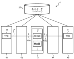
- FIG. 10 is a diagram showing an example of the configuration of an optical transmission system 1 including an all-optical wavelength conversion unit 13.
- the optical transmission system 1 includes five optical transmission devices 41, 42, 43, 44, and 45, and a network controller 20.
- the five optical transmission devices 41 to 45 are arranged in a line, for example, at locations spaced apart from each other by a certain distance.
- the optical transmission devices 41 to 45 are connected in series to each other via a single optical fiber cable 15 used as a transmission path for optical signals.
- the network controller 20 manages the entire optical communication network, which is made up of the optical transmission devices 41 to 45 and the optical fiber cable 15. For example, if any fault occurs on the optical communication network, the network controller 20 can generate information that is useful for identifying the location of the fault.
- optical transmission device 41 when transmitting data from optical transmission device 41 at one end of this communication network to optical transmission device 45 at the other end, optical transmission device 41 becomes the transmitting node and optical transmission device 45 becomes the receiving node.
- optical transmission devices 42 to 44 between these transmitting and receiving nodes are each used as relay nodes.
- the optical transmission device 41 of the sending node converts the data to be transmitted from an electrical signal to an optical signal of a specified wavelength inside the transponder 11, and sends this optical signal to the optical fiber cable 15.
- the optical transmission device 45 of the receiving node receives the optical signal from the optical fiber cable 15, and converts the optical signal to an electrical signal in the transponder 11 inside the optical transmission device 45 to obtain the received data.
- an optical transmission device 43 used as one relay node is equipped with an all-optical wavelength conversion unit 13 that implements the function of AO-WC (All Optical Wavelength Conversion).
- the all-optical wavelength conversion unit 13 in the optical transmission device 43 converts the wavelength of the input optical signal Oin with a wavelength of ⁇ 1 input from the optical fiber cable 15 to the optical transmission device 43 while it is still an optical signal, generates an optical signal with a wavelength of ⁇ 2 different from the input, and can send it to the downstream optical fiber cable 15 as an outgoing optical signal Oo2 with a wavelength of ⁇ 2.
- the all-optical wavelength conversion unit 13 shown in FIG. 10 can extract unnecessary optical components other than the optical main signal relayed inside the optical transmission device 43 and input them to the detector 11A in the optical transmission device 43.
- the detector 11A has the function of electrical termination processing like the transponder 11, but does not have the function of sending optical signals. In other words, the detector 11A has the function of converting the input optical signal into an electrical signal and the function of processing this electrical signal to detect transmission quality data.
- the optical transmission device 43 relays the main optical signal to be relayed as an optical signal without electrical termination and sends it to the downstream optical fiber cable 15, preventing an increase in delay due to relay processing. Also, as described below, there is no need to use an optical splitter to extract the optical signal input to the detector 11A, preventing a decrease in the optical intensity of the main optical signal.
- the all-optical wavelength conversion unit 13 extracts unnecessary optical components separate from the main optical signal being relayed and inputs them to the detector 11A in the optical transmission device 43, so that the detector 11A can detect transmission quality data at the node position of the optical transmission device 43.
- the network controller 20 can therefore obtain transmission quality data for relay nodes such as the optical transmission device 43 that does not perform electrical termination processing. For example, if a fault occurs, the network controller 20 can determine whether or not a fault has occurred for each section based on the transmission quality data at the position of each relay node.
- FIG. 11 is a diagram showing an example of the configuration of the all-optical wavelength conversion unit 13 included in the optical transmission system 1 of FIG.
- the all-optical wavelength conversion unit 13 includes a pumping light source 14, an optical fiber 15A, an optical multiplexer 16, a nonlinear optical medium 17, an optical demultiplexer 18, and an optical fiber 15B.
- the all-optical wavelength conversion unit 13 is an all-optical wavelength conversion device including a nonlinear optical medium 17 onto which both the optical main signal to be relayed and the pumping light emitted from the pumping light source 14 can be simultaneously incident.
- the pumping light source 14 generates pumping light Oe with a predetermined wavelength ⁇ e.
- the pumping light Oe generated by the pumping light source 14 passes through the optical fiber 15A and enters the optical multiplexer 16.
- the wavelength ⁇ e of the pumping light Oe is different from the wavelength ⁇ 1 of the input optical signal Oin.
- the optical intensity of the pumping light Oe is sufficiently greater than that of the input optical signal Oin.
- the optical multiplexer 16 generates light by multiplexing the input optical signal Oin input from the optical fiber cable 15 and the excitation light Oe input from the optical fiber 15A, and sends it to the input end of the nonlinear optical medium 17.
- the nonlinear optical medium 17 has nonlinear optical properties and can generate an optical signal with a wavelength different from that of the incident light.
- any one of highly nonlinear fiber (HNLF), periodically poled lithium niobate (PPLN), and a semiconductor optical amplifier (SOA) can be used as the nonlinear optical medium 17.
- the optical splitter 18 is connected to the light output side of the nonlinear optical medium 17, which is an all-optical wavelength conversion device.
- the output light Oout output from the output end of the nonlinear optical medium 17 is input to the optical splitter 18.
- the optical splitter 18 splits the incident light using its wavelength selection characteristics and extracts two types of optical signals. That is, the outgoing optical signal Oo2 with wavelength ⁇ 2 and the output light Oo1 with wavelength ⁇ 1 are output from different output terminals of the optical splitter 18.
- the wavelength ⁇ 2 of the outgoing optical signal Oo2 is generated based on the wavelength of the input optical signal Oin, the wavelength ⁇ e of the pump light Oe, and the nonlinear optical characteristics of the nonlinear optical medium 17.
- the input optical signal Oin with wavelength ⁇ 1 passes through the nonlinear optical medium 17 together with the pump light Oe, generating the wavelength ⁇ 2 of the wavelength-converted outgoing optical signal Oo2.
- the light emitted from the nonlinear optical medium 17 also contains an optical component with the same wavelength ⁇ 1 as before the wavelength conversion.
- the outgoing optical signal Oo2 with wavelength ⁇ 2 output from the optical splitter 18 is sent as a relay output from the output of the optical transmission device 43 to the downstream optical fiber cable 15.
- the outgoing light Oo1 with wavelength ⁇ 1 output from the optical splitter 18 is input to the detector 11A in the optical transmission device 43 via the optical fiber 15B.
- the wavelength of the optical main signal relayed by the optical transmission device 43 can be converted from ⁇ 1 to ⁇ 2 without electrical termination processing, preventing an increase in delay.
- the output light Oo1 of the same wavelength ⁇ 1 as before the wavelength conversion output from the all-optical wavelength conversion unit 13, i.e., unnecessary optical components other than the main signal can be input to the detector 11A.
- the detector 11A internally converts the input output light Oo1 of wavelength ⁇ 1 into an electrical signal, and various processes can be performed in the form of an electrical signal. This allows transmission quality data at the relay node position of the optical transmission device 43 to be obtained.
- the wavelength ⁇ 2 of the optical main signal sent by the relay node is different from the wavelength ⁇ 1 of the light other than the main signal input to detector 11A. Therefore, the correlation between the transmission quality detected for wavelength ⁇ 1 and the transmission quality detected for wavelength ⁇ 2 is specified in advance, and the transmission quality data detected by detector 11A is converted into transmission quality data of the optical signal to be relayed based on the correlation. This conversion process may be performed inside detector 11A or on the network controller 20 side.
- the optical transmission system 1 shown in FIG. 10 provides a method for detecting an optical signal generated in the AO-WC of the optical node device before or after wavelength conversion.
- peripheral devices optical attenuators and optical amplifiers
- the present invention was made in light of this background, and it is an object of the present invention to provide an optical transmission device and an optical transmission method that are capable of autonomously adjusting the output light intensity.
- an optical transmission device that can be installed in at least one optical relay node of an optical transmission system in which an optical transmitting node capable of transmitting an optical signal and an optical receiving node capable of receiving an optical signal are connected via an optical transmission path and one or more optical relay nodes are connected to an intermediate position of the optical transmission path, is characterized in that the optical transmission device comprises an input optical intensity adjustment unit that adjusts the optical intensity of a transmission wavelength signal input to the optical relay node, a wavelength conversion unit that converts the wavelength of the transmission wavelength signal whose optical intensity has been adjusted by the input optical intensity adjustment unit, a wavelength separation unit that separates the relayed transmission wavelength signal into the transmission wavelength signal having the same wavelength as before the wavelength conversion and a monitoring wavelength signal other than the transmission wavelength signal, an output optical intensity adjustment unit that adjusts the optical intensity of the transmission wavelength signal separated by the wavelength separation unit, a measurement unit that measures the transmission quality of the monitoring wavelength signal separated by the wavelength separation unit, and a control unit that controls the input optical intensity adjustment unit, the wavelength separation unit,
- the present invention makes it possible to realize an optical transmission device and an optical transmission method capable of autonomously adjusting the output light intensity.
- FIG. 1 is a schematic configuration diagram of an optical transmission device according to an embodiment of the present invention.
- FIG. 2 is a detailed configuration diagram of an optical transmission device according to an embodiment of the present invention.
- 1 is a detailed configuration diagram of an optical transmission device according to an embodiment of the present invention in which an optical amplifier is arranged.
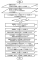
- 11 is a flowchart showing an operation of outputting signal light wavelength-converted by a WSS of an optical transmission device according to an embodiment of the present invention to ports ⁇ 2> to ⁇ n>.
- 1 is a configuration example in which signal light wavelength-converted by a WSS in an optical transmission device according to an embodiment of the present invention is output to a port ⁇ 1>.
- FIG. 11 is a flowchart illustrating an operation of outputting signal light wavelength-converted by a WSS of an optical transmission device according to an embodiment of the present invention to a port ⁇ 1>.
- FIG. 1 is a block diagram showing an example of the configuration of a typical optical transmission system.
- FIG. 1 is a block diagram showing an example of the configuration of a typical optical transmission system.
- FIG. 1 is a schematic diagram illustrating an example of the relationship between optical communication links and wavelength bands in multi-band networking technology.
- 1 is a block diagram showing an example of the configuration of an optical transmission system according to an embodiment of the present invention.
- 11 is a block diagram showing an example of the configuration of an all-optical wavelength conversion unit included in the optical transmission system of FIG. 10 .
- FIG. 1 is a schematic diagram of an optical transmission device according to an embodiment of the present invention.
- the optical transmission device according to this embodiment is applicable to the optical transmission system 1 in Fig. 10.
- the same components as those in Fig. 11 are denoted by the same reference numerals.
- the optical transmission device 100 is a transmission quality monitoring device that can be installed in at least one optical relay node of an optical transmission system 1 (Fig. 10) in which an optical transmitting node capable of transmitting an optical signal and an optical receiving node capable of receiving an optical signal are connected via an optical transmission path, and one or more optical relay nodes are connected to intermediate positions of the optical transmission path.
- the optical transmission device 100 includes a control unit 110, an optical input terminal 101, an optical output terminal 102, an input light intensity monitor 120 (input light intensity adjustment unit), a wavelength conversion unit 130, a wavelength selective switch (WSS) 140 (wavelength separation unit), a monitor measuring device 150 (measurement unit), and an output light intensity monitor 160 (output light intensity adjustment unit).
- a control unit 110 an optical input terminal 101, an optical output terminal 102, an input light intensity monitor 120 (input light intensity adjustment unit), a wavelength conversion unit 130, a wavelength selective switch (WSS) 140 (wavelength separation unit), a monitor measuring device 150 (measurement unit), and an output light intensity monitor 160 (output light intensity adjustment unit).
- WSS wavelength selective switch
- the input optical power monitor 120 adjusts the optical power of the transmission wavelength signal input to the optical relay node. Specifically, the input optical power monitor 120 adjusts the input optical power so that the appropriate optical power is input to the wavelength conversion unit 130.
- the wavelength conversion unit 130 converts the wavelength of the transmission wavelength signal whose optical intensity has been adjusted by the input optical intensity monitor 120.
- the wavelength conversion unit 130 also generates a monitoring wavelength signal from the transmission wavelength signal.
- the wavelength selective switch (WSS) 140 separates the relayed transmission wavelength signal into a transmission wavelength signal having the same wavelength as before the wavelength conversion and a monitoring wavelength signal (monitoring signal light) other than the transmission wavelength signal.
- the monitor measuring instrument 150 measures the signal quality of the monitoring wavelength signal.
- the output light intensity monitor 160 adjusts the light intensity of the transmission wavelength signal separated by the WSS 140.
- the output light intensity monitor 160 also adjusts the output light intensity of the wavelength conversion unit 130.
- Fig. 2 is a detailed configuration diagram of the optical transmission device 100 in Fig. 1.
- Fig. 2 shows a configuration example in which signal light wavelength-converted by the WSS 140 is output to ports ⁇ 2> to ⁇ n>.
- the control unit 110 sets the maximum input light intensity to the nonlinear optical medium 131, closes the input side optical shutter 124 before the input side optical power meter 122 starts measuring the input light intensity, controls the input side optical shutter 124 so that the input light intensity measured by the input side optical power meter 122 is equal to or less than the maximum input light intensity, and opens the input side optical shutter 124 after the input side optical power monitor 120 has completed adjustment.
- control unit 110 closes the output side optical shutter 164 to start measuring the output light intensity with the output side optical power meter 162, controls the output light intensity monitor 160 so that the output light intensity measured by the output side optical power meter 162 becomes the specified output light intensity, and opens the output side optical shutter 164 after adjustment by the output side optical power monitor 160 is completed.
- an input light intensity monitor 120 adjusts the input light intensity so that the input light is input to a wavelength conversion section 130 at an appropriate light intensity.
- the input light intensity monitor 120 includes a VOA (Variable Optical Attenuator) 121 , an input side optical power meter 122 , a beam splitter 123 , and an input side optical shutter 124 .
- VOA Very Optical Attenuator
- the VOA 121 variably attenuates the intensity of the optically transmitted optical signal upon receiving an instruction from the control unit 110 (receiving a control signal/voltage control signal from the control unit 110, the same applies below).
- the VOA 121 performs power management within the input optical power monitor 120 by voltage control from the control unit 110.
- the VOA 121 corresponds to wavelengths of, for example, C band, L band, and C+L band (FIG. 9).
- the input side optical power meter 122 measures the intensity (power) of light.
- the input side optical power meter 122 measures the output of the wavelength light source in the input optical power monitor 120 here.
- Beam splitter 123 splits an optical signal from one input channel into two or more optical signals.
- beam splitter 123 splits the optical signal from VOA 121 connected to optical input terminal 101 port ⁇ 1> into an optical signal output to wavelength conversion unit 130 and an optical signal output to input side optical power meter 122. Note that the wavelength and power remain unchanged after splitting by beam splitter 123.
- the input-side optical shutter 124 performs high-speed optical shutter control (control to transmit light only at specified times and block light at other times) using voltage control from the control unit 110.
- the input-side optical shutter 124 prevents light from entering the wavelength conversion unit 130 at the light intensity before adjustment is completed.
- the wavelength conversion unit 130 is a wavelength signal duplication functional unit that generates a monitoring wavelength signal (supervisory signal light) from a transmission wavelength signal.
- the wavelength conversion section 130 includes a nonlinear optical medium 131 , a pumping light source 132 , and an optical multiplexer 133 .
- the wavelength conversion section 130 is an all-optical wavelength conversion device including a nonlinear optical medium 131 onto which both the optical main signal to be relayed and the pumping light emitted from a pumping light source 132 can be simultaneously incident.
- the pumping light source 132 receives instructions from the control unit 110 and generates pumping light Oe of a predetermined wavelength ⁇ e.
- the pumping light Oe generated by the pumping light source 132 passes through the optical fiber 15A and enters the optical multiplexer 133.
- the wavelength ⁇ e of the pumping light Oe is different from the wavelength ⁇ 1 of the input optical signal Oin.
- the optical intensity of the pumping light Oe is sufficiently greater than that of the input optical signal Oin.
- the nonlinear optical medium 131 has nonlinear optical properties and can generate an optical signal with a wavelength different from that of the incident light.
- any one of highly nonlinear fiber (HNLF), periodically poled lithium niobate (PPLN), and a semiconductor optical amplifier (SOA) can be used as the nonlinear optical medium 131.
- HNLF highly nonlinear fiber
- PPLN periodically poled lithium niobate
- SOA semiconductor optical amplifier
- the WSS 140 is connected to the light output side of the nonlinear optical medium 131, which is an all-optical wavelength conversion device.
- the WSS 140 includes an optical demultiplexer (not shown), which receives instructions from the control unit 110, demultiplexes the incident light using wavelength selection characteristics, and extracts two types of optical signals.
- the WSS 140 outputs an output optical signal Oo2 with a wavelength ⁇ 2 and an output light Oo1 with a wavelength ⁇ 1 from a plurality of mutually different ports ⁇ 1>, ⁇ 2>, ..., ⁇ n>.
- the wavelength ⁇ 2 of the outgoing optical signal Oo2 is generated based on the wavelength of the input optical signal Oin, the wavelength ⁇ e of the pump light Oe, and the nonlinear optical characteristics of the nonlinear optical medium 131.
- the input optical signal Oin with wavelength ⁇ 1 passes through the nonlinear optical medium 131 together with the pump light Oe, generating the wavelength ⁇ 2 of the wavelength-converted outgoing optical signal Oo2.
- the outgoing light from the nonlinear optical medium 131 also contains an optical component with the same wavelength ⁇ 1 as before the wavelength conversion.
- the outgoing optical signal Oo2 with wavelength ⁇ 2 output from WSS 140 is sent as a relay output from the output of the optical transmission device 100 to the downstream optical fiber cable 15.
- the outgoing light Oo1 with wavelength ⁇ 1 output from WSS 140 is input to the monitor measuring instrument 150 via optical fiber 15B.
- the monitoring measuring instrument 150 measures the signal quality of the monitoring wavelength signal (monitoring signal light).
- the monitor measuring instrument 150 is a receiver 151 (more specifically, a detector provided in the receiver) of the optical transmission device 100 (hereinafter, this detector will be referred to as the receiver 151).
- the receiver 151 corresponds to, for example, the receiving section of a transponder (TPD). Like a transponder, it has an electrical termination function, but does not have the function of transmitting an optical signal.
- the receiver 151 has a function of converting an input optical signal into an electrical signal, and a function of processing this electrical signal to detect transmission quality data.
- the receiver equivalent to the transponder receiving section converts unnecessary light into an electrical signal and processes it to obtain transmission quality data.
- the receiver 151 may also be a spectrum analyzer, a polarization monitor, or a power meter.
- a spectrum analyzer is an electrical measuring instrument that displays a two-dimensional graph on a screen with frequency on the horizontal axis and power or voltage on the vertical axis. In the case of a spectrum analyzer, the signal-to-noise ratio is obtained. In the case of a polarization monitor, the polarization state of the optical signal is obtained, and in the case of a power meter, the optical intensity is obtained.
- the monitor measuring device 150 measures the signal light that is output to ports ⁇ 2>, ..., ⁇ n> and wavelength-converted by the WSS.
- a receiver 151 may be provided for each port ⁇ 2>, ..., ⁇ n>, or may be shared for multiple ports. Also, the receiver 151 may be a combination of multiple types of measuring devices.
- the output optical intensity monitor 160 includes a VOA 161 , an output-side optical power meter 162 , a beam splitter 163 , and an output-side optical shutter 164 .
- the VOA 161 variably attenuates the intensity of the optically transmitted optical signal under instructions from the control unit 110.
- the VOA 161 performs power management within the output optical power monitor 160 by voltage control from the control unit 110.
- the output side optical power meter 162 measures the intensity (power) of the light incident on the output optical power monitor 160 .
- the beam splitter 163 splits an optical signal from one input channel into two or more optical signals.
- the beam splitter 163 splits the optical signal from the VOA 161 connected to the port ⁇ 1> into an optical signal output to the optical output terminal 102 and an optical signal output to the output side optical power meter 162.
- the output-side optical shutter 164 performs high-speed optical shutter control under voltage control from the control unit 110.
- the output-side optical shutter 164 prevents light from being output to the outside at the light intensity before adjustment is completed.
- the optical transmission device 100 shown in FIG. 3 adds an optical amplifier 171 to the output side of the input light power monitor 120 (before the wavelength conversion unit 130) to amplify the output light of the input light power monitor 120.
- the optical transmission device 100 adds an optical amplifier 171 to amplify the output light of the nonlinear optical medium 131. Note that only one of the optical amplifier 171 on the output side of the input light power monitor 120 and the optical amplifier 171 on the output side of the nonlinear optical medium 131 may be placed according to the above conversion efficiency/gain.
- step S3 the input light intensity monitor 120 measures the input light intensity Pin using the input side optical power meter 122.
- step S4 the control unit 110 determines whether the measured input light intensity Pin is greater than a preset maximum input light intensity Pmax (Pin>Pmax).
- the maximum input light intensity Pmax to the nonlinear optical medium 131 is set in advance.
- step S6 the control unit 110 opens the input-side optical shutter 124 of the input light intensity monitor 120.
- the input light signals Oin of each component of wavelengths ⁇ 1 to ⁇ n (hereinafter simply referred to as input light signals of wavelengths ⁇ 1 to ⁇ n) are input from the input light intensity monitor 120 to the optical multiplexer 133 of the wavelength conversion unit 130 through the optical fiber cable 15.
- the wavelength of the input light signal Oin in Figure 2 is not a single wavelength, the above white waveforms are written in a rectangular shape (the same applies to the method of writing wavelength-converted signal light described below).
- step S7 the pump light source 14 generates pump light Oe with a single wavelength ⁇ e, and inputs the pump light Oe with wavelength ⁇ e to the optical multiplexer 133 via the optical fiber 15A.
- step S8 the optical multiplexer 133 multiplexes the input optical signal Oin of wavelengths ⁇ 1 to ⁇ n from the input optical intensity monitor 120 with the pumping light Oe from the pumping light source 14, and inputs the multiplexed signal to the nonlinear optical medium 131. Note that the optical intensity of the pumping light Oe is sufficiently greater than that of the input optical signal Oin.
- the nonlinear optical medium 131 of the wavelength conversion unit 130 passes both the input optical signal Oin of wavelengths ⁇ 1 to ⁇ n and the pump light Oe of wavelength ⁇ e, and generates signal light Oo2 obtained by wavelength-converting the input optical signal Oin of wavelengths ⁇ 1 to ⁇ n, with mirror symmetry around the pump light Oe as the center wavelength, based on the nonlinear optical characteristics of the nonlinear optical medium 131.
- the nonlinear optical medium 131 also outputs the wavelength-converted signal light Oo2 and the optical component Oo1 of wavelengths ⁇ 1 to ⁇ n that are the same as those before the wavelength conversion.
- the output light Oout of the nonlinear optical medium 131 also contains the wavelength-converted signal light Oo2 (see the hatched waveform indicated above the arrow of the output light Oout in FIG. 2) and the optical component Oo1 of wavelengths ⁇ 1 to ⁇ n that are the same as those before the wavelength conversion (see the outlined waveform indicated above the arrow of the output light Oout in FIG. 2).
- the output light Oout emitted from the nonlinear optical medium 131 contains optical components Oo1 with wavelengths ⁇ 1 to ⁇ n, a wavelength ⁇ e, and wavelength-converted signal light Oo2.
- the wavelength-converted signal light Oo2 is a component generated by wavelength conversion of the input optical signal Oin as it passes through the nonlinear optical medium 131.
- the optical intensity of the wavelength-converted signal light Oo2 component contained in the output light Oout depends on the nonlinear optical medium and the excitation light intensity, and can be made equivalent to that of the input optical signal Oin. For this reason, wavelength conversion can be performed without attenuating the optical intensity.
- optical intensity of the optical component Oo1 of wavelengths ⁇ 1 to ⁇ n contained in the output light Oout is equivalent to that of the input optical signal Oin. Therefore, optical signals other than the main signal with the same wavelengths ⁇ 1 to ⁇ n as before the wavelength conversion can be extracted from the output of the nonlinear optical medium 131 with sufficiently high optical intensity.
- step S10 the WSS140 transmits the wavelength-converted signal light Oo2 to ports ⁇ 2> through ⁇ n> as a monitoring signal light, and transmits the outgoing optical signal Oo1 to port ⁇ 1> of the monitor channel.
- step S11 the control unit 110 adjusts the output optical signal Oo1 to Pout at the VOA 161 while measuring it with the output optical power meter 162 (the output optical shutter 164 is closed).
- step S12 the control unit 110 opens the output side optical shutter 164 of the output light intensity monitor 160.
- each receiver 151 of the monitor measuring instrument 150 measures the transmission quality of the monitoring signal light Oo2 transmitted to ports ⁇ 2> to ⁇ n>, obtains the measurement data, and transmits the measurement data to the control unit 110, thereby completing the processing of this flow.
- a supervisory optical signal Oo2 having a sufficiently high optical intensity is input to each receiver 151, each receiver 151 can easily detect the transmission quality data at the position of the corresponding relay node.
- the above flow procedure makes it possible to adjust the output light intensity. It is also possible to make the output light intensity the same as the input light intensity.
- FIG. 5 shows an example of a configuration in which the signal light wavelength-converted by the WSS 140 is output to a port ⁇ 1>.
- the same components as those in FIG. 2 are denoted by the same reference numerals.
- Fig. 6 is a flowchart showing an operation of outputting the signal light wavelength-converted by the WSS of the optical transmission device 100 shown in Fig. 5 to the port ⁇ 1>.
- the same processing parts as those in Fig. 4 are assigned the same reference numerals, and the description of the overlapping parts will be omitted.
- Step S2A replaces step S2 in Figure 4.
- the operator sets the pre-input information (the wavelength setting of the channel to be monitored, and the output optical power Pout).
- the wavelength setting of the channel to be monitored is set so that the signal light wavelength-converted by the WSS is output to port ⁇ 1>.
- Step S10A replaces step S10 in FIG. 4.
- the WSS 140 transmits the wavelength-converted signal light Oo2 to port ⁇ 1> as the outgoing optical signal Oo1, and transmits the outgoing optical signal Oo2 of the same wavelengths ⁇ 1 to ⁇ n as before the wavelength conversion to ports ⁇ 2> to ⁇ n> of the monitor channel as the monitoring signal light.
- the above flow procedure makes it possible to adjust the output light intensity. It is also possible to make the output light intensity the same as the input light intensity.
- the device can be used as both a monitoring device and a wavelength converter.
- the optical transmission device 100 (FIGS. 1, 2, 3, and 5) can be installed in at least one optical relay node of the optical transmission system 1 (FIG. 10) in which an optical transmitting node capable of transmitting an optical signal and an optical receiving node capable of receiving an optical signal are connected via an optical transmission line, and one or more optical relay nodes are connected to intermediate positions of the optical transmission line.
- the optical transmission device 100 includes an input optical intensity adjuster (input optical intensity monitor 120) that adjusts the optical intensity of a transmission wavelength signal input to the optical relay node, and a wavelength converter that converts the wavelength of the transmission wavelength signal whose optical intensity has been adjusted by the input optical intensity adjuster.
- the wavelength conversion unit 130 converting the wavelength of the transmission wavelength signal into a wavelength signal having the same wavelength as that before the wavelength conversion
- a wavelength separation unit WSS 140
- WSS 140 separating the transmission wavelength signal to be relayed into a transmission wavelength signal having the same wavelength as that before the wavelength conversion and a monitoring wavelength signal other than the transmission wavelength signal
- an output light intensity adjustment unit output light intensity monitor 160
- a measurement unit monitoring measurement instrument 150 measuring the transmission quality of the monitoring wavelength signal separated by the wavelength separation unit
- a control unit 110 controlling the input light intensity adjustment unit, the wavelength separation unit, and the output light intensity adjustment unit.
- the input light intensity adjustment unit (input light intensity monitor 120) can suppress the deterioration of transmission quality by appropriately adjusting the input light intensity.
- the wavelength conversion unit 130 generates a monitoring wavelength signal from the transmission wavelength signal.
- the output light intensity adjustment unit (output light intensity monitor 160) appropriately outputs the light intensity of the output transmission wavelength signal.
- the measurement unit (monitoring measurement device 150) measures the transmission quality of the monitoring wavelength signal.
- Each of these functional units is controlled by the control unit 110. Therefore, it is possible to realize a transmission quality monitoring device that can autonomously adjust the output light intensity.
- the optical transmission device 100 can minimize the deterioration of the transmission performance of the transmission wavelength signal, or eliminate the need to readjust the optical level diagram. As a result, it is possible to introduce the device with minimal impact on existing optical transmission devices.
- the optical transmission device 100 relays the relayed transmission wavelength signal as an optical signal without electrical termination and sends it to the downstream optical fiber cable 15, preventing an increase in delay due to relay processing.
- the control unit 110 can obtain transmission quality data of relay nodes such as optical transmission devices that do not perform electrical termination processing. For example, if a failure occurs, the control unit 110 can determine whether or not a failure has occurred for each section based on the transmission quality data at the position of each relay node.
- the optical transmission device 100 can also switch the transmission wavelength signal and the wavelength-converted signal light by having the control unit 110 set each port ⁇ 1>, ⁇ 2>, ..., ⁇ n> of the WSS 140.
- the optical transmission device 100 transmits each optical component of wavelengths ⁇ 1 to ⁇ n, detects each optical component of the wavelength-converted signal light as a monitoring wavelength signal, and acquires transmission quality data ( Figures 2, 3, and 4).
- the optical transmission device 100 also transmits each optical component of wavelengths ⁇ 1 to ⁇ n, detects each optical component of wavelengths ⁇ 1 to ⁇ n as an extracted signal, and acquires transmission quality data ( Figures 5 and 6).
- the optical transmission device 100 can acquire transmission quality data even when wavelength conversion is not performed. In other words, since the light after wavelength conversion is used as the transmission signal light, it can be used as both a monitoring device and a wavelength converter.
- the optical transmission device 100 (Figs. 1, 2, 3, 5) includes an excitation light source 132 (Figs. 2, 3, 5) that emits excitation light of a wavelength different from the wavelength before wavelength conversion of the transmission wavelength signal to be relayed, and the wavelength conversion unit 130 is a nonlinear optical medium 131 (Figs. 2, 3, 5) into which both the transmission wavelength signal to be relayed and the excitation light emitted from the excitation light source 132 can be simultaneously incident, and the wavelength separation unit (WSS 140) separates the light emitted from the nonlinear optical medium 131 into an optical component with a wavelength after wavelength conversion and an optical component with a wavelength before wavelength conversion.
- WSS 140 wavelength separation unit
- the optical intensity of the wavelength-converted signal light components contained in the output light Oout from the nonlinear optical medium 131 depends on the nonlinear optical medium 131 and the pump light intensity, and can be made equivalent to the input optical signal Oin. Therefore, wavelength conversion can be performed without attenuating the optical intensity. Furthermore, the optical intensity of the optical components of wavelengths ⁇ 1 to ⁇ n contained in the output light Oout is equivalent to that of the input optical signal Oin. Therefore, optical signals other than the main signal with the same wavelengths ⁇ 1 to ⁇ n as before the wavelength conversion can be extracted from the output of the nonlinear optical medium 131 with sufficiently large optical intensity.
- the input light intensity adjustment unit (input light intensity monitor 120) is characterized by having an input side light shutter 124 (Figs. 2, 3, 5) that blocks the input of the transmission wavelength signal so that the transmission wavelength signal is not input to the wavelength conversion unit 130 at the light intensity before adjustment is completed, and the output light intensity adjustment unit (output light intensity monitor 160) is characterized by having an output side light shutter 164 (Figs. 2, 3, 5) that blocks the output of the transmission wavelength signal so that the transmission wavelength signal is not output at the light intensity before adjustment is completed.
- the input light intensity monitor 120 and the output light intensity monitor 160 have the input side optical shutter 124 and the output side optical shutter 164, and can perform input light intensity adjustment and output light intensity adjustment in an environment where the optical transmission path is temporarily closed to prevent unnecessary input and output ( Figures 4 and 6).
- the input light intensity adjustment unit (input light intensity monitor 120) includes an input side adjustment unit (VOA 121) (Figs. 2, 3, 5) that adjusts the input light intensity to the nonlinear optical medium 131, an input side optical power meter 122 (Figs. 2, 3, 5) that measures the input light intensity, and an input side optical shutter 124 (Figs. 2, 3, 5) that blocks the input of the transmission wavelength signal.
- the control unit 110 (Figs.
- the output light intensity adjustment unit (output light intensity monitor 160) includes an output side adjustment unit (VOA 161) (Figs. 2, 3, 5) that adjusts the amount of light output so that the output light intensity becomes a predetermined output light intensity, an output side optical power meter 162 that measures the output light intensity, and an output side optical shutter 164 that blocks the output of the transmission wavelength signal.
- the control unit 110 closes the output side optical shutter 164 before the output side optical power meter 162 starts measuring the output light intensity, controls the output side adjustment unit so that the output light intensity measured by the output side optical power meter 162 becomes the predetermined output light intensity, and opens the output side optical shutter 164 after adjustment by the output adjustment unit is completed.
- the optical transmission device 100 (Figs. 1, 2, 3, and 5) is characterized in that an optical amplifier 171 (Fig. 3) that amplifies the signal light is disposed on the output side of the input light intensity adjustment unit (input light intensity monitor 120) and/or on the output side of the wavelength separation unit (WSS 140).
- an optical amplifier 171 (Fig. 3) that amplifies the signal light is disposed on the output side of the input light intensity adjustment unit (input light intensity monitor 120) and/or on the output side of the wavelength separation unit (WSS 140).
- the optical amplifier 171 By doing this, by arranging the optical amplifier 171 on the output side of the input light intensity monitor 120, it is possible to amplify the input light when the input light intensity is low. Also, by arranging the optical amplifier 171 immediately after the output from the WSS 140, it is possible to amplify the output light when the gain/conversion efficiency of the nonlinear optical medium 131 is low.
- the network controller 20 ( Figure 10) of the optical transmission system 1, it is generally assumed that the "Pre-FEC BER" is used as the transmission quality data detected by the transponder 11 of each optical relay node. Meanwhile, the detector 11A and the transponder 11 can obtain data such as the amount of chromatic dispersion compensation, polarization mode dispersion, and polarization dependent loss in addition to the "Pre-FEC BER" by electrical signal processing of the communication data. Therefore, the network controller 20 can collect data such as the amount of chromatic dispersion compensation, polarization mode dispersion, and polarization dependent loss from each optical relay node that implements the detector 11A or the transponder 11, and use this data as learning data for machine learning. This helps to realize failure prediction in optical networks without electrical termination processing.
- each of the above configurations, functions, processing units, processing means, etc. may be realized in hardware, for example by designing some or all of them as an integrated circuit.
- each of the above configurations, functions, etc. may be realized by software that causes a processor to interpret and execute a program that realizes each function.
- Information on the programs, tables, files, etc. that realize each function can be stored in a memory, a recording device such as a hard disk or SSD (Solid State Drive), or a recording medium such as an IC (Integrated Circuit) card, SD (Secure Digital) card, or optical disc.
Landscapes
- Physics & Mathematics (AREA)
- Electromagnetism (AREA)
- Engineering & Computer Science (AREA)
- Computer Networks & Wireless Communication (AREA)
- Signal Processing (AREA)
- Optical Communication System (AREA)
Abstract
Description
本発明は、光伝送装置および光伝送方法に関する。 The present invention relates to an optical transmission device and an optical transmission method.
送信ノードと受信ノードとの間を比較的長距離の光ファイバケーブルで接続し、光信号の伝送を行う光伝送システムにおいては、伝送路の途中で光信号が大きく減衰したり、伝送品質の劣化が生じることが予想される。したがって、送信ノードから送信された光信号を確実に受信ノードに届けるために、一般的には伝送路の途中に1つ以上の中継ノードを配置して、減衰した光信号を増幅する、また伝送路の途中で発生したビットエラーなどを訂正する必要がある。 In optical transmission systems that connect a sending node and a receiving node with a relatively long-distance optical fiber cable and transmit optical signals, it is expected that the optical signal will be significantly attenuated along the transmission path, and that degradation in transmission quality will occur. Therefore, to ensure that the optical signal sent from the sending node is delivered to the receiving node reliably, it is generally necessary to place one or more relay nodes along the transmission path to amplify the attenuated optical signal and to correct bit errors that occur along the transmission path.
また、通常は一定の距離毎に中継ノードを配置する必要があるので、長距離の光伝送を行う場合は多数の中継ノードが送信ノードと受信ノードの間の伝送路の中間部に接続される。 In addition, relay nodes usually need to be placed at regular intervals, so when transmitting optically over long distances, many relay nodes are connected to the middle of the transmission path between the transmitting node and the receiving node.
光伝送システムの各中継ノードは、通常は電気終端処理の機能を備えている。すなわち、受信した光信号を電気信号に一旦変換し、変換された電気信号の情報を中継処理する。また、電気信号の情報を処理する際に、当該中継ノードにおける伝送品質データ(Pre-FEC BER、分散補償量、偏波モード分散量、偏波依存損失)を取得できる。 Each relay node in an optical transmission system is usually equipped with an electrical termination function. In other words, it first converts the received optical signal into an electrical signal, and then relays the information of the converted electrical signal. In addition, when processing the information of the electrical signal, it is possible to obtain transmission quality data (Pre-FEC BER, dispersion compensation amount, polarization mode dispersion amount, polarization dependent loss) at the relay node.
しかし、各中継ノードで電気終端処理を行うと、電気信号の中継処理に伴う遅延時間の増大は避けられない。また、電気信号の中継処理に伴って電力消費が増大する。また、光伝送の際に利用可能な波長リソースに制約があるので伝送容量拡大の妨げになる。 However, if electrical termination is performed at each relay node, an increase in delay time due to relaying of electrical signals is unavoidable. In addition, relaying of electrical signals increases power consumption. Furthermore, there are limitations on the wavelength resources available for optical transmission, which hinders the expansion of transmission capacity.
一方、近年では光ファイバケーブルや光送信機の機能が向上している。そこで、電気終端処理の機能を備えた中継ノードを配置する間隔を拡大する傾向がある。これにより、電気終端処理を行いながら中継するノードの数が減るためネットワークの省電力化、大容量化、低遅延化が可能になる。 On the other hand, the functionality of optical fiber cables and optical transmitters has improved in recent years. As a result, there is a trend to increase the spacing between relay nodes equipped with electrical termination processing functions. This reduces the number of relay nodes performing electrical termination processing, making it possible to reduce power consumption, increase capacity, and reduce latency in the network.
一方、例えば非特許文献1は光ノード装置における電気終端処理を省略した光トランスポートネットワークの技術を開示している。また、非特許文献1は限られた波長リソースを効率的に使用するため、経由する光ノード装置において、光信号の波長を他の波長へ変換する波長変換機能の導入について開示している。
On the other hand, for example, Non-Patent
ところで、光伝送システムに障害が発生した場合には、障害箇所を特定する必要がある。そのためには、最初に長距離の伝送路の全長を中継ノード毎の複数の区間に分離して、区間毎に故障発生の有無の切り分けを行う必要がある。 When a fault occurs in an optical transmission system, it is necessary to identify the location of the fault. To do this, it is first necessary to separate the entire length of the long-distance transmission line into multiple sections at each relay node, and then determine whether or not a fault has occurred in each section.
各中継ノードが電気終端処理の機能を実装している場合には、中継ノード毎に伝送品質データを取得できる。各中継ノードの伝送品質データを比較することで、区間毎の故障発生の有無の切り分けが可能になる。 If each relay node is equipped with an electrical termination function, transmission quality data can be obtained for each relay node. By comparing the transmission quality data of each relay node, it becomes possible to determine whether or not a fault has occurred in each section.
しかし、電気終端処理の機能を実装していない中継ノードについてはその地点の伝送品質データが得られない。そのため、故障有無の切り分けが可能な区間のそれぞれの中に多数の光伝送装置が含まれたり、区間毎の光ファイバケーブルの長さが非常に長くなる状況になる。そのため、障害箇所の特定が困難になる。 However, for relay nodes that do not implement electrical termination processing functionality, transmission quality data cannot be obtained at that point. This results in a situation where each section where it is possible to isolate whether or not there is a fault contains a large number of optical transmission devices, and the length of the optical fiber cable for each section becomes very long. This makes it difficult to identify the location of the fault.
そこで、例えば中継ノードに光スプリッタを配置することが考えられる。すなわち、中継ノードが受信した1つの光信号を光スプリッタで2つの経路に分岐して、一方の経路の主信号は光信号のままで中継し、他方の経路の光信号は電気信号に変換して伝送品質データの取得のために利用する。これにより、中継に伴う光主信号の信号遅延を低減できる。しかし、入力された光信号が光スプリッタを通過する際に中継する光主信号の光強度が低下するため、中継ノードで伝送品質の劣化が発生する。 So, for example, an optical splitter can be placed at the relay node. That is, one optical signal received by the relay node is split into two paths by the optical splitter, and the main signal on one path is relayed as an optical signal, while the optical signal on the other path is converted to an electrical signal and used to obtain transmission quality data. This reduces the signal delay of the optical main signal that occurs during relaying. However, because the optical intensity of the relayed main optical signal decreases when the input optical signal passes through the optical splitter, degradation of transmission quality occurs at the relay node.
<光伝送システムの構成>
図7は、一般的な光伝送システム1Aの構成例を示す図である。
図7に示すように、光伝送システム1Aは、7つの光伝送装置10-1、10-2、10-3、10-4、10-5、10-6、および10-7が一例に並び、共通の光ファイバケーブル15を経由して互いに直列に接続されている。また、これらの光伝送装置10-1~10-7を含む通信ネットワークを管理するためにネットワークコントローラ20が各光伝送装置10-1~10-7に接続されている。
<Configuration of Optical Transmission System>
FIG. 7 is a diagram showing an example of the configuration of a typical optical transmission system 1A.
7, the optical transmission system 1A includes seven optical transmission devices 10-1, 10-2, 10-3, 10-4, 10-5, 10-6, and 10-7, which are connected in series to each other via a common
例えば、この通信ネットワークの一端側の光伝送装置10-1から他端側の光伝送装置10-7に対してデータを伝送する場合、光伝送装置10-1が送信ノードとなり、光伝送装置10-7が受信ノードとなる。また、これらの送信ノード、受信ノードの間にある光伝送装置10-2~10-6は、それぞれ中継ノードとして使用される。 For example, when transmitting data from optical transmission device 10-1 at one end of this communication network to optical transmission device 10-7 at the other end, optical transmission device 10-1 becomes the transmitting node and optical transmission device 10-7 becomes the receiving node. In addition, optical transmission devices 10-2 to 10-6 located between these transmitting and receiving nodes are each used as relay nodes.
送信ノードの光伝送装置10-1は、送信するデータをトランスポンダ(TPD:Transponder)11の内部で電気信号から所定波長の光信号に変換し、この光信号を光ファイバケーブル15に送出する。受信ノードの光伝送装置10-7は、光ファイバケーブル15から光信号を受け取り、光伝送装置10-7内のトランスポンダ11で光信号を電気信号に変換して受信データを取得する。
The optical transmission device 10-1 at the sending node converts the data to be transmitted from an electrical signal to an optical signal of a specific wavelength inside the transponder (TPD: Transponder) 11, and sends this optical signal to the
光信号伝送の距離が長くなると、光強度が低下し、ビットエラーレート(BER)などの伝送品質の劣化が発生する。また、光強度が著しく低下し、ビットエラーレートが著しく増大すると、受信ノードの光伝送装置10-7が送信されたデータを正しく受信できない状態になる。 As the distance of optical signal transmission increases, the optical intensity decreases, causing degradation of transmission quality, such as the bit error rate (BER). Furthermore, if the optical intensity decreases significantly and the bit error rate increases significantly, the optical transmission device 10-7 at the receiving node will be unable to correctly receive the transmitted data.
そのため、各中継ノードの光伝送装置10-2~10-6が所定の中継処理を実行する。具体的には、各中継ノードがそれぞれの中継位置で受信した光信号の光強度を増幅して、所定のエラー訂正処理によりビットエラーのない元のデータを復元する。 To this end, the optical transmission devices 10-2 to 10-6 at each relay node perform a predetermined relay process. Specifically, each relay node amplifies the optical intensity of the optical signal received at each relay position, and restores the original data without bit errors using a predetermined error correction process.
ただし、エラー訂正処理などを行うためには、伝送する光信号の電気終端処理を行う必要がある。具体的には、光伝送装置10-2~10-6は、トランスポンダ11内で光信号を電気信号に変換し、得られた電気信号のデータを処理してエラー訂正処理などを行う。更に、光伝送装置10-2~10-6は、処理の終了した電気信号を再び光信号に変換し、中継出力として下流側の光ファイバケーブル15へ送出する。
However, to perform error correction and other processing, it is necessary to perform electrical termination processing of the optical signal being transmitted. Specifically, the optical transmission devices 10-2 to 10-6 convert the optical signal into an electrical signal within the
上記のような電気終端処理を行うと、伝送中に発生したエラーを確実に訂正すると共に光強度を回復することができる。また、伝送品質データを得ることもできる。しかし、電気信号の処理に伴ってトランスポンダ11の内部で信号に比較的大きな遅延が発生する。また、伝送距離が長くなると中継回数が増えるので、遅延時間が増大する。光伝送システム1Aの例では、送信ノードと受信ノードの間に中継ノードとしてトランスポンダ11を含む光伝送装置10-3、および10-5が存在するので、電気終端処理を含む中継処理が1回だけの場合に比べて遅延時間が2倍になる。
By performing the electrical termination process as described above, it is possible to reliably correct errors that occur during transmission and restore the optical intensity. It is also possible to obtain transmission quality data. However, a relatively large delay occurs in the signal inside the
近年では、光ファイバケーブル15や光信号を送信する送信機の機能が向上しているので、比較的長距離の光伝送を行う場合でも、電気終端処理を含む中継ノードの中継数を減らすことが可能である。したがって、図7に示した光伝送システム1Aの構成を、図8の光伝送システム1Bのように改良することができる。
In recent years, the functionality of the
図8は、図7の光伝送システム1Aを改良した光伝送システム1Bの構成例を示す図である。
図8に示す光伝送システム1Bは、トランスポンダ11が光伝送装置10-1および10-7に存在するが、他の光伝送装置10-2~10-6にはトランスポンダ11がない。つまり、送信ノードの光伝送装置10-1から受信ノードの光伝送装置10-7に光信号を伝送する場合に、途中で電気終端処理を含む中継を1回も行わない。したがって、光伝送システム1Bの光信号伝送に伴う遅延時間は、光伝送システム1Aと比べて大幅に削減される。
FIG. 8 is a diagram showing an example of the configuration of an
8, the
光伝送システム1Bは、光伝送装置10-2~10-6の各々にトランスポンダ11がなく、電気終端処理を行わないので、各光伝送装置10-2~10-6の中継ノードの位置で伝送品質データを得ることができない。
In the
通信の障害が発生すると、通常、ネットワークコントローラ20は光信号の伝送に使用している各ノードの位置で検出された伝送品質データに基づいて障害が発生した場所の候補を絞り込むために伝送区間の切り分けを行う。しかし、光伝送システム1Bの場合は各光伝送装置10-2~10-6の中継位置における伝送品質データが得られないので、光伝送装置10-1の出力と光伝送装置10-7の入力との間のどの区間で障害が発生しているのかを切り分けることができない。その結果、障害が発生している場所の特定が困難になり、障害の復旧に長い時間が必要になる。特に、光ファイバケーブル15の距離が非常に長い場合には、障害発生の場所を探すことが難しい。
When a communication failure occurs, the
<マルチバンドネットワーキング技術>
図9は、マルチバンドネットワーキング技術における光通信リンクと波長帯との関係の例を示す図である。
図9に示すように、通信に利用する光の波長帯として、Lバンド、Cバンド、およびSバンドの3種類がある場合を想定している。Lバンドとは、1565~1625 nmの波長帯域である。Cバンドとは、1530~1565 nmの波長帯域である。Sバンドとは、1460~1530 nmの波長帯域である。
また、Lバンド、Cバンド、およびSバンドのそれぞれは互いに独立した光路(Optical path)を有している。また、図9の例では、互いに独立した2つの光通信リンク31、および32がある場合を想定している。
<Multi-band networking technology>
FIG. 9 is a diagram showing an example of the relationship between optical communication links and wavelength bands in multi-band networking technology.
As shown in Figure 9, it is assumed that there are three types of optical wavelength bands used for communication: L-band, C-band, and S-band. The L-band is a wavelength band from 1565 to 1625 nm. The C-band is a wavelength band from 1530 to 1565 nm. The S-band is a wavelength band from 1460 to 1530 nm.
In addition, the L band, the C band, and the S band each have an optical path independent of each other. In addition, in the example of Fig. 9, it is assumed that there are two
各光通信リンク31、32の光信号は、状況に応じてアダプティブにバンド切り替えされ、複数バンドの光路を跨ぐようにスイッチングされる。図9中に示した光通信リンク31の光信号は、Lバンドの光路を通過した後、波長変換によりCバンドの光信号に変換されてCバンドの光路に入り、更に波長変換によりSバンドの光信号に変換されてSバンドの光路に入る。この光は、次に波長変換によりLバンドの光信号に変換されてLバンドの光路に入り、Ph-EX(Photonic Exchange)で電気信号に変換されて処理されて出力される。Ph-EXは、交換、多重、スイッチングといった電気処理を極小化した構成要素である。
The optical signals of each
また、Cバンドの波長の光通信リンク32の光信号は、Cバンドの光路を通過した後、波長変換によりSバンドの光信号に変換されてSバンドの光路に入り、Ph-EXで電気信号に変換されて処理される。
In addition, the optical signal of the
図9に示したような技術を利用することで、光伝送システムは、限られた波長リソースを効率的に使用できる。具体的には、伝送路の収容トラヒック量を30%程度増やすことができる。また、各通信ノードの位置で電気終端処理を省略して、光信号のまま処理できるので、ネットワークの省電力化、大容量化、低遅延化などの効果が期待できる。ただし、各ノード位置の光伝送装置は、光信号を波長変換する機能を実装する必要がある。 By using technology such as that shown in Figure 9, optical transmission systems can efficiently use limited wavelength resources. Specifically, the traffic volume that can be accommodated on a transmission path can be increased by about 30%. In addition, because electrical termination processing can be omitted at each communication node and optical signals can be processed as is, benefits such as reduced power consumption, increased capacity, and reduced latency can be expected for the network. However, the optical transmission equipment at each node needs to be equipped with a function to convert the wavelength of optical signals.
図10は、全光波長変換部13を備える光伝送システム1の構成例を示す図である。
図10に示すように、光伝送システム1は、5つの光伝送装置41、42、43、44、および45と、ネットワークコントローラ20と、を備える。5つの光伝送装置41~45は、例えば一定の距離だけ互いに離れた場所に一列に並べて設置されている。また、光伝送装置41~45は光信号の伝送路として利用される1つの光ファイバケーブル15を介して互いに直列に接続されている。
FIG. 10 is a diagram showing an example of the configuration of an
10, the
ネットワークコントローラ20は、光伝送装置41~45、および光ファイバケーブル15で構成される光通信ネットワークの全体を管理している。ネットワークコントローラ20は、例えば光通信ネットワーク上で何らかの障害が発生した場合に、障害の発生場所を特定するために役立つ情報を生成できる。
The
例えば、この通信ネットワークの一端側の光伝送装置41から他端側の光伝送装置45に対してデータを伝送する場合、光伝送装置41が送信ノードとなり、光伝送装置45が受信ノードとなる。また、これらの送信ノード、受信ノードの間にある光伝送装置42~44は、それぞれ中継ノードとして使用される。
For example, when transmitting data from
送信ノードの光伝送装置41は、送信するデータをトランスポンダ11の内部で電気信号から所定波長の光信号に変換し、この光信号を光ファイバケーブル15に送出する。受信ノードの光伝送装置45は、光ファイバケーブル15から光信号を受け取り、光伝送装置45内のトランスポンダ11で光信号を電気信号に変換して受信データを取得する。
The
図10に示した構成においては、1つの中継ノードとして使用される光伝送装置43の内部にAO-WC(All Optical Wavelength Conversion:全光波長変換)の機能を実装した全光波長変換部13を備えている。
In the configuration shown in FIG. 10, an
光伝送装置43内の全光波長変換部13は、光ファイバケーブル15から光伝送装置43に入力された波長がλ1の入力光信号Oinを光信号のままで波長変換処理して、入力と異なる波長λ2の光信号を生成し、波長λ2の送出光信号Oo2として下流側の光ファイバケーブル15に送出することができる。また、図10中に示した全光波長変換部13は、光伝送装置43の内部で中継する光主信号とは別の不要光成分を抽出して光伝送装置43内の検出器11Aに入力することができる。検出器11Aは、トランスポンダ11と同様に電気終端処理の機能を有しているが、光信号を送出する機能はない。すなわち、検出器11Aは入力された光信号を電気信号に変換する機能と、この電気信号を処理して伝送品質データを検出する機能とを有している。
The all-optical
光伝送装置43は、中継する光主信号を電気終端処理することなく、光信号のまま中継して下流側の光ファイバケーブル15に送出するので、中継処理に伴う遅延の増大を防止できる。また、後述するように検出器11Aに入力する光信号を抽出するために光スプリッタを使う必要がないので、光主信号の光強度の低下を防止できる。
The
また、全光波長変換部13は、中継する光主信号とは別の不要光成分を抽出して光伝送装置43内の検出器11Aに入力するので、検出器11Aは光伝送装置43のノード位置における伝送品質データを検出できる。
In addition, the all-optical
したがって、ネットワークコントローラ20は電気終端処理を行わない光伝送装置43などの中継ノードの伝送品質データを取得できる。例えば障害が発生した場合に、ネットワークコントローラ20は各中継ノードの位置における伝送品質データに基づいて、区間毎に障害発生の有無を切り分けることができる。
The
<全光波長変換部の構成>
図11は、図10の光伝送システム1に含まれる全光波長変換部13の構成例を示す図である。
図11に示すように、全光波長変換部13は、励起光光源14、光ファイバ15A、光合波器16、非線形光学媒質17、光分波器18、および光ファイバ15Bを備える。
全光波長変換部13は、中継する光主信号、および、励起光光源14から出射される励起光の両方の光が同時に入射可能な非線形光学媒質17を含んだ全光波長変換デバイスである。
<Configuration of all-optical wavelength conversion unit>
FIG. 11 is a diagram showing an example of the configuration of the all-optical
As shown in FIG. 11, the all-optical
The all-optical
励起光光源14は、所定の波長λeの励起光Oeを生成する。励起光光源14が生成した励起光Oeは、光ファイバ15Aを通って光合波器16に入射する。励起光Oeの波長λeは入力光信号Oinの波長λ1とは異なる。また、励起光Oeの光強度は入力光信号Oinと比べて十分に大きい。
The pumping
光合波器16は、光ファイバケーブル15から入力される入力光信号Oinと光ファイバ15Aから入力される励起光Oeとを合波した光を生成して非線形光学媒質17の入射端に送出する。
The
非線形光学媒質17は、非線形光学特性を有し、入射光と異なる波長の光信号を生成することができる。代表例としては、高非線形ファイバ(HNLF)、周期分極反転ニオブ酸リチウム(PPLN)、および半導体光増幅器(SOA)のいずれか1つを非線形光学媒質17として利用できる。
The nonlinear
光分波器18は、全光波長変換デバイスである非線形光学媒質17の光出射側に接続されている。非線形光学媒質17の出力端から出射される出射光Ooutは光分波器18に入力される。光分波器18は、その波長選択特性により入射光を分波して、2種類の光信号をそれぞれ抽出する。すなわち、波長λ2の送出光信号Oo2と、波長λ1の出射光Oo1とが光分波器18の互いに異なる出力端子から出射される。
The
送出光信号Oo2の波長λ2は、入力光信号Oinの波長と、励起光Oeの波長λeと、非線形光学媒質17の非線形光学特性とに基づいて生成される。波長λ1の入力光信号Oinが励起光Oeと共に非線形光学媒質17を通過することで、波長変換された送出光信号Oo2の波長λ2が生成される。また、非線形光学媒質17の出射光の中には、波長変換前と同じ波長λ1の光成分も含まれている。
The wavelength λ2 of the outgoing optical signal Oo2 is generated based on the wavelength of the input optical signal Oin, the wavelength λe of the pump light Oe, and the nonlinear optical characteristics of the nonlinear
光分波器18から出力される波長λ2の送出光信号Oo2は、中継出力として光伝送装置43の出力から下流側の光ファイバケーブル15に送出される。また、光分波器18から出力される波長λ1の出射光Oo1は、光ファイバ15Bを介して光伝送装置43内の検出器11Aに入力される。
The outgoing optical signal Oo2 with wavelength λ2 output from the
このように、図11に示した全光波長変換部13を利用することで、光伝送装置43が中継する光主信号を電気終端処理することなく、光信号のままでその波長をλ1からλ2に変換し、遅延の増大を防止できる。また、全光波長変換部13から出力される波長変換前と同じ波長λ1の出射光Oo1、すなわち主信号以外の不要な光成分を検出器11Aに入力することができる。検出器11Aは、入力される波長λ1の出射光Oo1を内部で電気信号に変換し、電気信号の形態で各種処理を行うことができる。これにより、光伝送装置43の中継ノード位置における伝送品質データが得られる。
In this way, by using the all-optical
ただし、中継ノードが送出する光主信号の波長λ2と検出器11Aに入力される主信号以外の光の波長λ1とは異なっている。そこで、波長λ1に対して検出される伝送品質と波長λ2に対して検出される伝送品質との相関関係を事前に特定しておき、検出器11Aが検出した伝送品質データを、相関関係に基づいて中継する光信号の伝送品質データに変換する。この変換処理は、検出器11Aの内部で行ってもよいし、ネットワークコントローラ20側で行ってもよい。
However, the wavelength λ2 of the optical main signal sent by the relay node is different from the wavelength λ1 of the light other than the main signal input to detector 11A. Therefore, the correlation between the transmission quality detected for wavelength λ1 and the transmission quality detected for wavelength λ2 is specified in advance, and the transmission quality data detected by detector 11A is converted into transmission quality data of the optical signal to be relayed based on the correlation. This conversion process may be performed inside detector 11A or on the
図10に示す光伝送システム1では、光ノード装置のAO-WCにおいて生成される波長変換前または波長変換後の光信号を検出する手法を提供している。
しかしながら、上記の手法にあっては、AO-WCの入力光強度と出力光強度が異なることから、実際に光ノード装置として導入する際には、光強度を調整する周辺機器(光減衰器や光増幅器)が必要となる。
The
However, in the above method, since the input light intensity and output light intensity of the AO-WC are different, when actually introducing it as an optical node device, peripheral devices (optical attenuators and optical amplifiers) to adjust the light intensity are required.
このような背景を鑑みて本発明がなされたのであり、本発明は、自律的に出力光強度を調整することが可能な光伝送装置および光伝送方法を提供することを課題とする。 The present invention was made in light of this background, and it is an object of the present invention to provide an optical transmission device and an optical transmission method that are capable of autonomously adjusting the output light intensity.
前記した課題を解決するため、光信号の送信が可能な光送信ノードと、光信号の受信が可能な光受信ノードとの間が光伝送路を介して接続され、前記光伝送路の中間位置に1つ以上の光中継ノードが接続された光伝送システムの少なくとも1つの前記光中継ノードに装備可能な光伝送装置であって、前記光中継ノードに入力される伝送波長信号の光強度を調整する入力光強度調整部と、前記入力光強度調整部が光強度を調整した伝送波長信号の波長を変換する波長変換部と、中継する前記伝送波長信号を、波長変換前と波長が同じ前記伝送波長信号と、当該伝送波長信号以外のモニタリング用波長信号とに分ける波長分離部と、前記波長分離部が分離した前記伝送波長信号の光強度を調整する出力光強度調整部と、前記波長分離部が分離した前記モニタリング用波長信号の伝送品質を測定する測定部と、前記入力光強度調整部、前記波長分離部、および前記出力光強度調整部を制御する制御部と、を備えることを特徴とする光伝送装置とした。 In order to solve the above problem, an optical transmission device that can be installed in at least one optical relay node of an optical transmission system in which an optical transmitting node capable of transmitting an optical signal and an optical receiving node capable of receiving an optical signal are connected via an optical transmission path and one or more optical relay nodes are connected to an intermediate position of the optical transmission path, is characterized in that the optical transmission device comprises an input optical intensity adjustment unit that adjusts the optical intensity of a transmission wavelength signal input to the optical relay node, a wavelength conversion unit that converts the wavelength of the transmission wavelength signal whose optical intensity has been adjusted by the input optical intensity adjustment unit, a wavelength separation unit that separates the relayed transmission wavelength signal into the transmission wavelength signal having the same wavelength as before the wavelength conversion and a monitoring wavelength signal other than the transmission wavelength signal, an output optical intensity adjustment unit that adjusts the optical intensity of the transmission wavelength signal separated by the wavelength separation unit, a measurement unit that measures the transmission quality of the monitoring wavelength signal separated by the wavelength separation unit, and a control unit that controls the input optical intensity adjustment unit, the wavelength separation unit, and the output optical intensity adjustment unit.
本発明によれば、自律的に出力光強度を調整することが可能な光伝送装置および光伝送方法を実現することができる。 The present invention makes it possible to realize an optical transmission device and an optical transmission method capable of autonomously adjusting the output light intensity.
以下、図面を参照して本発明を実施するための形態(以下、「本実施形態」という)における光伝送装置等について説明する。
[概要]
図1は、本発明の実施形態に係る光伝送装置の概略構成図である。
本実施形態に係る光伝送装置は、図10の光伝送システム1に適用可能である。図11と同一構成部分には、同一符号を付している。
Hereinafter, an optical transmission device and the like in an embodiment of the present invention (hereinafter, referred to as "the present embodiment") will be described with reference to the drawings.
[overview]
FIG. 1 is a schematic diagram of an optical transmission device according to an embodiment of the present invention.
The optical transmission device according to this embodiment is applicable to the
光伝送装置100は、光信号の送信が可能な光送信ノードと、光信号の受信が可能な光受信ノードとの間が光伝送路を介して接続され、光伝送路の中間位置に1つ以上の光中継ノードが接続された光伝送システム1(図10)の少なくとも1つの光中継ノードに装備可能な伝送品質モニタリング装置である。
The
図1に示すように、光伝送装置100は、制御部110と、光入力端子101と、光出力端子102と、入力光強度モニタ120(入力光強度調整部)と、波長変換部130と、波長選択スイッチ(WSS:Wavelength Selective Switch)140(波長分離部)と、モニタ用測定器150(測定部)と、出力光強度モニタ160(出力光強度調整部)と、を備える。
As shown in FIG. 1, the
入力光強度モニタ120は、光中継ノードに入力される伝送波長信号の光強度を調整する。具体的には、入力光強度モニタ120は、波長変換部130に適切な光強度で入力するための入力光強度を調整する。
The input
波長変換部130は、入力光強度モニタ120が光強度を調整した伝送波長信号の波長を変換する。また、波長変換部130は、伝送波長信号からモニタリング用波長信号を生成する。
The
波長選択スイッチ(WSS)140は、中継する伝送波長信号を、波長変換前と波長が同じ伝送波長信号と、当該伝送波長信号以外のモニタリング用波長信号(監視用信号光)とに分ける。 The wavelength selective switch (WSS) 140 separates the relayed transmission wavelength signal into a transmission wavelength signal having the same wavelength as before the wavelength conversion and a monitoring wavelength signal (monitoring signal light) other than the transmission wavelength signal.
モニタ用測定器150は、モニタリング用波長信号の信号品質を測定する。
The
出力光強度モニタ160は、WSS140が分離した伝送波長信号の光強度を調整する。また、出力光強度モニタ160は、波長変換部130の出力光強度を調整する。
The output light intensity monitor 160 adjusts the light intensity of the transmission wavelength signal separated by the
[詳細構成]
図2は、図1の光伝送装置100の詳細構成図である。図2は、WSS140で波長変換された信号光をポート<2>~<n>に出力する構成例である。
[Detailed configuration]
Fig. 2 is a detailed configuration diagram of the
<制御部110>
制御部110は、制御部110は、測定した入力光強度Pinがあらかじめ設定された最大入力光強度Pmaxより大きいか否かを判別し、入力光強度モニタ120のVOA121がPin=PmaxまたはPin<Pmaxになるよう調整する。
<
The
制御部110は、非線形光学媒質131への最大入力光強度を設定し、入力側光パワーメータ122の測定開始前には、入力側光シャッタ124を閉じて入力側光パワーメータ122による入力光強度の測定を開始し、入力側光パワーメータ122で測定した入力光強度が最大入力光強度以下となるように入力光強度モニタ120を制御し、入力光強度モニタ120による調整完了後、入力側光シャッタ124を開く。
The
また、制御部110は、出力側光パワーメータ162の測定開始前には、出力側光シャッタ164を閉じて出力側光パワーメータ162による出力光強度の測定を開始し、出力側光パワーメータ162で測定した出力光強度が所定出力光強度となるように出力光強度モニタ160を制御し、出力光強度モニタ160による調整完了後、出力側光シャッタ164を開く。
In addition, before the output side
<入力光強度モニタ120>
図2において、入力光強度モニタ120は、波長変換部130に適切な光強度で入力するための入力光強度を調整する。
入力光強度モニタ120は、VOA(Variable Optical Attenuator:可変光アッテネータ)121、入力側光パワーメータ(Optical power meter)122、ビームスプリッタ123および入力側光シャッタ124を備える。
<Input
In FIG. 2, an input light intensity monitor 120 adjusts the input light intensity so that the input light is input to a
The input light intensity monitor 120 includes a VOA (Variable Optical Attenuator) 121 , an input side
VOA121は、制御部110の指示(制御部110から制御信号/電圧制御信号を受信することをいう、以下同様。)を受け、光伝送された光信号強度を可変減衰させる。VOA121は、入力光強度モニタ120内のパワーマネージメントを、制御部110からの電圧制御によって行う。VOA121は、例えばCバンド,Lバンド,C+Lバンドの波長(図9)に対応する。
入力側光パワーメータ122は、光の強度(パワー)を測定する。入力側光パワーメータ122は、ここでは入力光強度モニタ120内の波長光源の出力を測定する。
The
The input side
ビームスプリッタ123は、1つの入力チャネルからの光信号を2つ以上の光信号に分割する。ここでは、ビームスプリッタ123は、光入力端子101ポート<1>に接続されたVOA121からの光信号を波長変換部130側に出力される光信号と、入力側光パワーメータ122に出力される光信号とに分割する。なお、ビームスプリッタ123で分割した後の波長やパワーは変わらない。
入力側光シャッタ124は、制御部110からの電圧制御によって、高速に光シャッタ制御(所定時のみ光を透過させ、それ以外の時は光を遮る制御)を行う。入力側光シャッタ124は、調整完了前の光強度で波長変換部130に入力しないようにする。
The input-side
<波長変換部130>
波長変換部130は、伝送波長信号からモニタリング用波長信号(監視用信号光)を生成する波長信号複製機能部である。
波長変換部130は、非線形光学媒質131、励起光光源132、および光合波器133を備える。
波長変換部130は、中継する光主信号、および、励起光光源132から出射される励起光の両方の光が同時に入射可能な非線形光学媒質131を含んだ全光波長変換デバイスである。
<
The
The
The
励起光光源132は、制御部110の指示を受け、所定の波長λeの励起光Oeを生成する。励起光光源132が生成した励起光Oeは、光ファイバ15Aを通って光合波器133に入射する。励起光Oeの波長λeは入力光信号Oinの波長λ1とは異なる。また、励起光Oeの光強度は、入力光信号Oinと比べて十分に大きい。
The pumping
光合波器133は、光ファイバケーブル15から入力される入力光信号Oinと光ファイバ15Aから入力される励起光Oeとを合波した光を生成して非線形光学媒質131の入射端に送出する。
The
非線形光学媒質131は、非線形光学特性を有し、入射光と異なる波長の光信号を生成することができる。代表例としては、高非線形ファイバ(HNLF)、周期分極反転ニオブ酸リチウム(PPLN)、および半導体光増幅器(SOA)のいずれか1つを非線形光学媒質131として利用できる。
The nonlinear
<波長選択スイッチ(WSS)140>
WSS140は、全光波長変換デバイスである非線形光学媒質131の光出射側に接続されている。WSS140は、図示しない光分波器を備え、この光分波器は、制御部110の指示を受け、波長選択特性により入射光を分波して、2種類の光信号をそれぞれ抽出する。WSS140は、波長λ2の送出光信号Oo2と、波長λ1の出射光Oo1とが、互いに異なる複数のポート<1>,<2>,…,<n>から出射される。
<Wavelength Selective Switch (WSS) 140>
The
送出光信号Oo2の波長λ2は、入力光信号Oinの波長と、励起光Oeの波長λeと、非線形光学媒質131の非線形光学特性とに基づいて生成される。波長λ1の入力光信号Oinが励起光Oeと共に非線形光学媒質131を通過することで、波長変換された送出光信号Oo2の波長λ2が生成される。また、非線形光学媒質131の出射光の中には、波長変換前と同じ波長λ1の光成分も含まれている。
The wavelength λ2 of the outgoing optical signal Oo2 is generated based on the wavelength of the input optical signal Oin, the wavelength λe of the pump light Oe, and the nonlinear optical characteristics of the nonlinear
WSS140から出力される波長λ2の送出光信号Oo2は、中継出力として光伝送装置100の出力から下流側の光ファイバケーブル15に送出される。また、WSS140から出力される波長λ1の出射光Oo1は、光ファイバ15Bを介してモニタ用測定器150に入力される。
The outgoing optical signal Oo2 with wavelength λ2 output from
<モニタ用測定器150>
モニタ用測定器150は、モニタリング用波長信号(監視用信号光)の信号品質を測定する。
モニタ用測定器150は、光伝送装置100の受信機151(より詳細には、受信機に備えられた検出器)である(以下、この検出器を受信機151と呼ぶ)。受信機151は、例えば、トランスポンダ(TPD)の受信部相当のものである。トランスポンダと同様に電気終端処理の機能を有しているが、光信号を送出する機能はない。受信機151は、入力された光信号を電気信号に変換する機能と、この電気信号を処理して伝送品質データを検出する機能とを有している。トランスポンダ受信部相当のものでは、不要光を電気信号に変換して処理することで伝送品質データを取得する。
<
The
The
また、受信機151は、スペクトラムアナライザ(Spectrum analyzer)、偏波モニタ、パワーメータを用いてもよい。スペクトラムアナライザは、横軸を周波数、縦軸を電力または電圧とする二次元のグラフを画面に表示する電気計測器である。スペクトラムアナライザの場合は、信号対雑音比を取得する。偏波モニタの場合は、光信号の偏波状態を取得し、パワーメータの場合は光強度を取得する。
The
図2では、モニタ用測定器150は、ポート<2>,…,<n>に出射されたWSSで波長変換された信号光を測定する。受信機151は、ポート<2>,…,<n>ごとに準備してもよく、複数のポート分を共用してもよい。また、受信機151は、複数種類の測定器を組合わせて用いてもよい。
In FIG. 2, the
<出力光強度モニタ160>
出力光強度モニタ160は、VOA161、出力側光パワーメータ162、ビームスプリッタ163および出力側光シャッタ164を備える。
VOA161は、制御部110の指示を受け、光伝送された光信号強度を可変減衰させる。VOA161は、出力光強度モニタ160内のパワーマネージメントを、制御部110からの電圧制御によって行う。
出力側光パワーメータ162は、出力光強度モニタ160に入射される光の強度(パワー)を測定する。
<Output
The output optical intensity monitor 160 includes a
The
The output side
ビームスプリッタ163は、1つの入力チャネルからの光信号を2つ以上の光信号に分割する。ここでは、ビームスプリッタ163は、ポート<1>に接続されたVOA161からの光信号を光出力端子102側に出力される光信号と、出力側光パワーメータ162に出力される光信号とに分割する。
出力側光シャッタ164は、制御部110からの電圧制御によって、高速に光シャッタ制御を行う。出力側光シャッタ164は、調整完了前の光強度で外部に出力しないようにする。
The
The output-side
図3は、図2の光伝送装置100に光増幅器171を配置した詳細構成図である。図2と同一構成部分には、同一符号を付している。
図3に示す光伝送装置100は、入力光強度モニタ120の出力側(波長変換部130の前段)に入力光強度モニタ120の出力を増幅する光増幅器171を配置している。また、WSS140の各ポート<1>,<2>,…,<n>にWSS140の出力を増幅する光増幅器171を配置している。
Fig. 3 is a detailed configuration diagram in which an
3, an
図3に示す光伝送装置100は、入力光強度モニタ120の変換効率/利得が低い場合に、入力光強度モニタ120の出力側(波長変換部130の前段)に光増幅器171を追加し、入力光強度モニタ120の出力光を増幅させる。また、光伝送装置100は、非線形光学媒質131の変換効率/利得が低い場合に、光増幅器171を追加し、非線形光学媒質131の出力光を増幅させる。なお、入力光強度モニタ120の出力側の光増幅器171と、非線形光学媒質131の出力側の光増幅器171とは、上記変換効率/利得に合わせていずれか一方のみを配置してもよい。
When the conversion efficiency/gain of the input
以下、上述のように構成された光伝送装置100の動作を説明する。
[WSSで波長変換された信号光をポート<2>~<n>に出力する動作例]
図4は、図2に示す光伝送装置100のWSSで波長変換された信号光をポート<2>~<n>に出力する動作を示すフローチャートである。
ステップS1で制御部110は、図示しない入力手段を用いて光伝送装置100内の仕様である、非線形光学媒質131への最大入力光強度Pmaxを設定する。
ステップS2で測定者が事前入力情報(モニタしたいチャネルの波長設定、および出力光強度Pout)を設定する。ここでは、モニタしたいチャネルの波長設定を、WSSで波長変換された信号光をポート<2>~<n>に出力するように設定する。
The operation of the
[Example of operation in which signal light wavelength-converted by the WSS is output to ports <2> to <n>]
FIG. 4 is a flowchart showing an operation of outputting the signal light wavelength-converted by the WSS of the
In step S1, the
In step S2, the operator sets the pre-input information (the wavelength setting of the channel to be monitored and the output optical power Pout). Here, the wavelength setting of the channel to be monitored is set so that the signal light wavelength-converted by the WSS is output to ports <2> to <n>.
ステップS3で入力光強度モニタ120は、入力側光パワーメータ122を用いて入力光強度Pinを測定する。
In step S3, the input light intensity monitor 120 measures the input light intensity Pin using the input side
ステップS4で制御部110は、測定した入力光強度Pinがあらかじめ設定された最大入力光強度Pmaxより大きいか(Pin>Pmaxか)否かを判別する。
In step S4, the
Pin>Pmaxの場合(S4:Yes)、ステップS5で制御部110は、入力光強度モニタ120のVOA121がPin=PmaxまたはPin<Pmaxになるよう調整する。Pin≦Pmaxの場合(S4:No)、そのままステップS6に進む。
If Pin>Pmax (S4: Yes), in step S5, the
ここで、非線形光学媒質131による波長変換では、高い入力光強度を入射すると利得飽和やチャネル間クロストーク等の非線形現象による伝送品質劣化が生じる。本実施形態では、非線形現象による伝送品質劣化を抑えるために、事前に非線形光学媒質131への最大入力光強度Pmaxを設定する。
Here, in wavelength conversion using the nonlinear
ステップS6で制御部110は、入力光強度モニタ120の入力側光シャッタ124を開ける。これにより、図2の入力光信号Oinの矢印上に表記された白抜き波形に示すように、入力光強度モニタ120から波長変換部130の光合波器133に光ファイバケーブル15を通して波長λ1~λnの各成分の入力光信号(以下、単に波長λ1~λn入力光信号という)Oinが入力される。なお、図2の入力光信号Oinの波長が単一でないことを示すため、上記白抜き波形は、矩形形状で表記している(後記する波長変換された信号光の表記方法も同様である)。
In step S6, the
ステップS7で励起光光源14は、単一の波長λeの励起光Oeを生成し、光ファイバ15Aを通して波長λeの励起光Oeを光合波器133に入力する。
In step S7, the
ステップS8で光合波器133は、入力光強度モニタ120の波長λ1~λnの入力光信号Oinと、励起光光源14の励起光Oeとを合波し、非線形光学媒質131に入力する。なお、励起光Oeの光強度は入力光信号Oinよりも十分に大きい。
In step S8, the
ステップS9で波長変換部130の非線形光学媒質131は、波長λ1~λnの入力光信号Oinと、波長λeの励起光Oeとを共に通過させることで、非線形光学媒質131の非線形光学特性に基づいて、励起光Oeを中心波長とするミラー対称で、波長λ1~λnの入力光信号Oinを波長変換した信号光Oo2を生成するとともに、波長変換された信号光Oo2と、波長変換前と同じ波長λ1~λnの光成分Oo1も出力する。すなわち、また、非線形光学媒質131の出射光Ooutの中には、波長変換された信号光Oo2(図2の出射光Ooutの矢印上に表記されたハッチング波形参照)と、波長変換前と同じ波長λ1~λnの光成分Oo1(図2の出射光Ooutの矢印上に表記された白抜き波形参照)も含まれている。
In step S9, the nonlinear
非線形光学媒質131から出射される出射光Ooutの中には、波長λ1~λnの光成分Oo1、波長λe、波長変換された信号光Oo2が含まれている。波長変換された信号光Oo2は、非線形光学媒質131の通過に伴う入力光信号Oinの波長変換によって生じた成分である。出射光Ooutに含まれる波長変換された信号光Oo2の成分の光強度は、非線形光学媒質および励起光強度に依存し、入力光信号Oinと同等とすることができる。このため、光強度を減衰させることなく波長変換を行うことができる。
The output light Oout emitted from the nonlinear
また、出射光Ooutに含まれる波長λ1~λnの光成分Oo1の光強度は、入力光信号Oinと同等である。このため、波長変換前と同じ波長λ1~λnで且つ主信号以外の光信号を非線形光学媒質131の出力から十分に大きい光強度で取り出すことができる。 In addition, the optical intensity of the optical component Oo1 of wavelengths λ1 to λn contained in the output light Oout is equivalent to that of the input optical signal Oin. Therefore, optical signals other than the main signal with the same wavelengths λ1 to λn as before the wavelength conversion can be extracted from the output of the nonlinear optical medium 131 with sufficiently high optical intensity.
ステップS10でWSS140は、波長変換された信号光Oo2を監視用信号光としてポート<2>~<n>へ伝送し、送出光信号Oo1をモニタチャネルのポート<1>へ伝送する。 In step S10, the WSS140 transmits the wavelength-converted signal light Oo2 to ports <2> through <n> as a monitoring signal light, and transmits the outgoing optical signal Oo1 to port <1> of the monitor channel.
ステップS11で制御部110は、送出光信号Oo1を出力側光パワーメータ162で測定しながらVOA161でPoutになるよう調整する(出力側光シャッタ164は閉じている)。
In step S11, the
ステップS12で制御部110は、出力光強度モニタ160の出力側光シャッタ164を開ける。
In step S12, the
ステップS13でモニタ用測定器150の各受信機151は、ポート<2>~<n>に伝送された監視用信号光Oo2の伝送品質を測定して測定データを取得し、制御部110に測定データを送信して本フローの処理を終了する。
ここで、十分に光強度の大きい監視用信号光Oo2が各受信機151に入力されるので、各受信機151は該当する中継ノードの位置における伝送品質データを容易に検出できる。
In step S13, each
Here, since a supervisory optical signal Oo2 having a sufficiently high optical intensity is input to each
上記フローの手順により、出力光強度を調整可能になる。また、出力光強度を入力光強度と同じにすることも可能である。 The above flow procedure makes it possible to adjust the output light intensity. It is also possible to make the output light intensity the same as the input light intensity.
[WSSで波長変換された信号光をポート<1>に出力する動作例]
図5は、WSS140で波長変換された信号光をポート<1>に出力する構成例である。図2と同一構成部分には、同一符号を付している。
図6は、図5に示す光伝送装置100のWSSで波長変換された信号光をポート<1>に出力する動作を示すフローチャートである。図4と同一処理部分には、同一符号を付して重複箇所の説明を省略する。
[Example of operation in which signal light wavelength-converted by the WSS is output to port <1>]
5 shows an example of a configuration in which the signal light wavelength-converted by the
Fig. 6 is a flowchart showing an operation of outputting the signal light wavelength-converted by the WSS of the
ステップS2Aは、図4のステップS2を置き換えたものである。ステップS2Aで測定者が事前入力情報(モニタしたいチャネルの波長設定、および出力光強度Pout)を設定する。ここでは、モニタしたいチャネルの波長設定を、WSSで波長変換された信号光をポート<1>に出力するように設定する。 Step S2A replaces step S2 in Figure 4. In step S2A, the operator sets the pre-input information (the wavelength setting of the channel to be monitored, and the output optical power Pout). Here, the wavelength setting of the channel to be monitored is set so that the signal light wavelength-converted by the WSS is output to port <1>.
ステップS10Aは、図4のステップS10を置き換えたものである。ステップS10AでWSS140は、波長変換された信号光Oo2を送出光信号Oo1としてポート<1>へ伝送し、波長変換前と同じ波長λ1~λnの送出光信号Oo2を監視用信号光としてモニタチャネルのポート<2>~<n>へ伝送する。
Step S10A replaces step S10 in FIG. 4. In step S10A, the
上記フローの手順により、出力光強度を調整可能になる。また、出力光強度を入力光強度と同じにすることも可能である。
また、波長変換した後の光を伝送信号光として使用することから、モニタ用装置かつ波長変換器としても使用可能である。
The above flow procedure makes it possible to adjust the output light intensity. It is also possible to make the output light intensity the same as the input light intensity.
In addition, since the light after wavelength conversion is used as a transmission signal light, the device can be used as both a monitoring device and a wavelength converter.
[効果]
以上説明したように、光信号の送信が可能な光送信ノードと、光信号の受信が可能な光受信ノードとの間が光伝送路を介して接続され、光伝送路の中間位置に1つ以上の光中継ノードが接続された光伝送システム1(図10)の少なくとも1つの光中継ノードに装備可能な光伝送装置100(図1、図2、図3、図5)であって、光中継ノードに入力される伝送波長信号の光強度を調整する入力光強度調整部(入力光強度モニタ120)と、入力光強度調整部が光強度を調整した伝送波長信号の波長を変換する波長変換部130と、中継する伝送波長信号を、波長変換前と波長が同じ伝送波長信号と、当該伝送波長信号以外のモニタリング用波長信号とに分ける波長分離部(WSS140)と、波長分離部が分離した伝送波長信号の光強度を調整する出力光強度調整部(出力光強度モニタ160)と、波長分離部が分離したモニタリング用波長信号の伝送品質を測定する測定部(モニタ用測定器150)と、入力光強度調整部、波長分離部、および出力光強度調整部を制御する制御部110と、を備える。
[effect]
As described above, the optical transmission device 100 (FIGS. 1, 2, 3, and 5) can be installed in at least one optical relay node of the optical transmission system 1 (FIG. 10) in which an optical transmitting node capable of transmitting an optical signal and an optical receiving node capable of receiving an optical signal are connected via an optical transmission line, and one or more optical relay nodes are connected to intermediate positions of the optical transmission line. The
このようにすることにより、入力光強度調整部(入力光強度モニタ120)では、入力光強度を適切に調整することで、伝送品質劣化を抑制することができる。波長変換部130では、伝送波長信号からモニタリング用波長信号を生成する。出力光強度調整部(出力光強度モニタ160)では、出力される伝送波長信号の光強度を適切に出力する。測定部(モニタ用測定器150)では、モニタリング用波長信号の伝送品質を測定する。これら各機能部は、制御部110によって制御される。したがって、自律的に出力光強度を調整することが可能な、伝送品質モニタリング装置を実現することができる。このように、光伝送装置100は、伝送波長信号の伝送性能の劣化を最低限に、もしくは光レベルダイヤの再調整を不要化させることができる。その結果、既存の光伝送装置への影響を最低限に抑えて導入することが可能となる。
In this way, the input light intensity adjustment unit (input light intensity monitor 120) can suppress the deterioration of transmission quality by appropriately adjusting the input light intensity. The
また、光伝送装置100は、中継する伝送波長信号を電気終端処理することなく、光信号のまま中継して下流側の光ファイバケーブル15に送出するので、中継処理に伴う遅延の増大を防止できる。また、測定部(モニタ用測定器150)に入力する光信号を抽出するために光スプリッタを使う必要がないので、伝送波長信号の光強度の低下を抑制できる。したがって、制御部110は、電気終端処理を行わない光伝送装置などの中継ノードの伝送品質データを取得できる。例えば障害が発生した場合に、制御部110は、各中継ノードの位置における伝送品質データに基づいて、区間毎の障害発生の有無を切り分けることができる。
In addition, the
また、光伝送装置100は、制御部110がWSS140各ポート<1>,<2>,…,<n>を設定することにより、伝送波長信号と波長変換された信号光を入れ替えることも可能である。例えば、光伝送装置100は、波長λ1~λnの各光成分を伝送し、波長変換された信号光の各光成分をモニタリング用波長信号として検出して、伝送品質データを取得する(図2、図3、図4)。また、光伝送装置100は、波長λ1~λnの各光成分を伝送し、波長λ1~λnの各光成分を抽出信号として検出して、伝送品質データを取得する(図5、図6)。この場合、光伝送装置100は、波長変換を行わない場合にも伝送品質データを取得することができる。すなわち、波長変換した後の光を伝送信号光として使用することから、モニタ用装置かつ波長変換器としても使用可能である。
The
光伝送装置100(図1、図2、図3、図5)において、中継する伝送波長信号の波長変換前の波長とは異なる波長の励起光を出射する励起光光源132(図2、図3、図5)を備え、波長変換部130は、中継する伝送波長信号、および励起光光源132から出射される励起光の両方の光が同時に入射可能な非線形光学媒質131(図2、図3、図5)であり、波長分離部(WSS140)は、非線形光学媒質131からの出射光を波長変換後の波長の光成分と波長変換前の波長の光成分とのそれぞれに分離する。
The optical transmission device 100 (Figs. 1, 2, 3, 5) includes an excitation light source 132 (Figs. 2, 3, 5) that emits excitation light of a wavelength different from the wavelength before wavelength conversion of the transmission wavelength signal to be relayed, and the
このようにすることにより、非線形光学媒質131からの出射光Oout(図2、図3、図5)に含まれる波長変換された信号光の成分の光強度は、非線形光学媒質131および励起光強度に依存し、入力光信号Oinと同等とすることができる。このため、光強度を減衰させることなく波長変換を行うことができる。また、出射光Ooutに含まれる波長λ1~λnの光成分の光強度は、入力光信号Oinと同等である。このため、波長変換前と同じ波長λ1~λnで且つ主信号以外の光信号を非線形光学媒質131の出力から十分に大きい光強度で取り出すことができる。
By doing this, the optical intensity of the wavelength-converted signal light components contained in the output light Oout from the nonlinear optical medium 131 (Figures 2, 3, 5) depends on the nonlinear
入力光強度調整部(入力光強度モニタ120)は、調整完了前の光強度で伝送波長信号が波長変換部130に入力しないように、伝送波長信号の入力を遮る入力側光シャッタ124(図2、図3、図5)を備え、出力光強度調整部(出力光強度モニタ160)は、調整完了前の光強度で伝送波長信号が出力しないように、伝送波長信号の出力を遮る出力側光シャッタ164(図2、図3、図5)を備えることを特徴とする。
The input light intensity adjustment unit (input light intensity monitor 120) is characterized by having an input side light shutter 124 (Figs. 2, 3, 5) that blocks the input of the transmission wavelength signal so that the transmission wavelength signal is not input to the
このようにすることにより、入力光強度モニタ120および出力光強度モニタ160は、入力側光シャッタ124,出力側光シャッタ164を有することで、光伝送路を一時的に閉じて不要入射および出射を防いだ環境下で、入力光強度調整および出力光強度調整を実行することができる(図4、図6)。
By doing this, the input
光伝送装置100(図1、図2、図3、図5)において、入力光強度調整部(入力光強度モニタ120)は、非線形光学媒質131への入力光強度を調整する入力側調整部(VOA121)(図2、図3、図5)と、入力光強度を測定する入力側光パワーメータ122(図2、図3、図5)と、伝送波長信号の入力を遮る入力側光シャッタ124(図2、図3、図5)と、を備え、制御部110(図2、図3、図5)は、非線形光学媒質131への最大入力光強度を設定し、入力側光パワーメータ122の測定開始前には、入力側光シャッタ124を閉じて入力側光パワーメータ122による入力光強度の測定を開始し、入力側光パワーメータ122で測定した入力光強度が最大入力光強度以下となるように入力側調整部を制御し、入力側調整部による調整完了後、入力側光シャッタ124を開くことを特徴とする。
In the optical transmission device 100 (Figs. 1, 2, 3, 5), the input light intensity adjustment unit (input light intensity monitor 120) includes an input side adjustment unit (VOA 121) (Figs. 2, 3, 5) that adjusts the input light intensity to the nonlinear
このようにすることにより、光伝送装置100への不要入射を防いだ環境下で、入力光強度調整を実行(図4、図6)することができ、入力光強度調整を正確に行うことができる。
By doing this, it is possible to perform input light intensity adjustment (Figures 4 and 6) in an environment where unnecessary input to the
光伝送装置100(図1、図2、図3、図5)において、出力光強度調整部(出力光強度モニタ160)は、出力光強度が所定出力光強度となるように光の出力量を調整する出力側調整部(VOA161)(図2、図3、図5)と、出力光強度を測定する出力側光パワーメータ162と、伝送波長信号の出力を遮る出力側光シャッタ164と、を備え、制御部110は、出力側光パワーメータ162の測定開始前には、出力側光シャッタ164を閉じて出力側光パワーメータ162による出力光強度の測定を開始し、出力側光パワーメータ162で測定した出力光強度が所定出力光強度となるように出力側調整部を制御し、出力調整部による調整完了後、出力側光シャッタ164を開くことを特徴とする。
In the optical transmission device 100 (Figs. 1, 2, 3, 5), the output light intensity adjustment unit (output light intensity monitor 160) includes an output side adjustment unit (VOA 161) (Figs. 2, 3, 5) that adjusts the amount of light output so that the output light intensity becomes a predetermined output light intensity, an output side
このようにすることにより、光伝送装置100からの出射を防いだ環境下で、入力光強度調整および出力光強度の調整を実行(図4、図6)することができ、後段の光伝送装置等への影響を抑制することができる。
By doing this, it is possible to adjust the input light intensity and the output light intensity (Figures 4 and 6) in an environment where emission from the
光伝送装置100(図1、図2、図3、図5)において、入力光強度調整部(入力光強度モニタ120)の出力側、および/または、波長分離部(WSS140)の出力側に信号光を増幅する光増幅器171(図3)を配置することを特徴とする。 The optical transmission device 100 (Figs. 1, 2, 3, and 5) is characterized in that an optical amplifier 171 (Fig. 3) that amplifies the signal light is disposed on the output side of the input light intensity adjustment unit (input light intensity monitor 120) and/or on the output side of the wavelength separation unit (WSS 140).
このようにすることにより、入力光強度モニタ120の出力側に光増幅器171を配置することで、入力光強度が小さい場合に、入力光を増幅させることができる。また、WSS140からの出力直後に光増幅器171を配置することで、非線形光学媒質131の利得/変換効率が低い場合に、出力光を増幅させることができる。
By doing this, by arranging the
なお、光伝送システム1のネットワークコントローラ20(図10)においては、各光中継ノードのトランスポンダ11が検出した伝送品質データとして「Pre-FEC BER」を使うことが一般的に想定される。一方、検出器11Aやトランスポンダ11は通信データの電気信号処理により「Pre-FEC BER」の他に、波長分散補償量、偏波モード分散、偏波依存損失等のデータも取得できる。したがって、ネットワークコントローラ20は、検出器11A又はトランスポンダ11を実装している各光中継ノードから波長分散補償量、偏波モード分散、偏波依存損失等のデータも収集し、機械学習の学習データとして活用できる。これにより、電気終端処理のない光ネットワークにおける故障予知の実現に役立つ。
In addition, in the network controller 20 (Figure 10) of the
また、上記実施形態において説明した各処理のうち、自動的に行われるものとして説明した処理の全部又は一部を手動的に行うこともでき、あるいは、手動的に行われるものとして説明した処理の全部又は一部を公知の方法で自動的に行うこともできる。この他、上述文書中や図面中に示した処理手順、制御手順、具体的名称、各種のデータやパラメータを含む情報については、特記する場合を除いて任意に変更することができる。
また、図示した各装置の各構成要素は機能概念的なものであり、必ずしも物理的に図示の如く構成されていることを要しない。すなわち、各装置の分散・統合の具体的形態は図示のものに限られず、その全部又は一部を、各種の負荷や使用状況などに応じて、任意の単位で機能的又は物理的に分散・統合して構成することができる。
Furthermore, among the processes described in the above embodiments, all or part of the processes described as being performed automatically can be performed manually, or all or part of the processes described as being performed manually can be performed automatically by a known method. In addition, the information including the processing procedures, control procedures, specific names, various data and parameters shown in the above documents and drawings can be changed arbitrarily unless otherwise specified.
In addition, each component of each device shown in the figure is a functional concept, and does not necessarily have to be physically configured as shown in the figure. In other words, the specific form of distribution and integration of each device is not limited to that shown in the figure, and all or part of them can be functionally or physically distributed and integrated in any unit depending on various loads, usage conditions, etc.
また、上記の各構成、機能、処理部、処理手段等は、それらの一部又は全部を、例えば集積回路で設計する等によりハードウェアで実現してもよい。また、上記の各構成、機能等は、プロセッサがそれぞれの機能を実現するプログラムを解釈し、実行するためのソフトウェアで実現してもよい。各機能を実現するプログラム、テーブル、ファイル等の情報は、メモリや、ハードディスク、SSD(Solid State Drive)等の記録装置、または、IC(Integrated Circuit)カード、SD(Secure Digital)カード、光ディスク等の記録媒体に保持することができる。 Furthermore, each of the above configurations, functions, processing units, processing means, etc. may be realized in hardware, for example by designing some or all of them as an integrated circuit. Furthermore, each of the above configurations, functions, etc. may be realized by software that causes a processor to interpret and execute a program that realizes each function. Information on the programs, tables, files, etc. that realize each function can be stored in a memory, a recording device such as a hard disk or SSD (Solid State Drive), or a recording medium such as an IC (Integrated Circuit) card, SD (Secure Digital) card, or optical disc.
1 光伝送システム
10-1,10-2,10-3,10-4,10-5 光伝送装置
11 トランスポンダ
11A 検出器
13 全光波長変換部
14 励起光光源
15 光ファイバケーブル
15A,15B 光ファイバ
16 光合波器
17 非線形光学媒質
18 光分波器
20 ネットワークコントローラ
31,32 光通信リンク
100 光伝送装置
110 制御部
101 光入力端子
102 光出力端子
120 入力光強度モニタ(入力光強度調整部)
121,161 VOA
122 入力側光パワーメータ
123,163 ビームスプリッタ
124 入力側光シャッタ
130 波長変換部
131 非線形光学媒質
132 励起光光源
133 光合波器
140 波長選択スイッチ(WSS)(波長分離部)
150 モニタ用測定器(測定部)
151 受信機
160 出力光強度モニタ(出力光強度調整部)
162 出力側光パワーメータ
164 出力側光シャッタ
171 光増幅器
1 Optical transmission system 10-1, 10-2, 10-3, 10-4, 10-5
121,161 VOA
122 Input side
150 Monitor measuring device (measuring part)
162 Output side
Claims (7)
前記光中継ノードに入力される伝送波長信号の光強度を調整する入力光強度調整部と、
前記入力光強度調整部が光強度を調整した伝送波長信号の波長を変換する波長変換部と、
中継する前記伝送波長信号を、波長変換前と波長が同じ前記伝送波長信号と、当該伝送波長信号以外のモニタリング用波長信号とに分ける波長分離部と、
前記波長分離部が分離した前記伝送波長信号の光強度を調整する出力光強度調整部と、
前記波長分離部が分離した前記モニタリング用波長信号の伝送品質を測定する測定部と、
前記入力光強度調整部、前記波長分離部、および前記出力光強度調整部を制御する制御部と、を備える
ことを特徴とする光伝送装置。 An optical transmission device that can be installed in at least one optical relay node of an optical transmission system in which an optical transmitting node capable of transmitting an optical signal and an optical receiving node capable of receiving an optical signal are connected via an optical transmission line, and one or more optical relay nodes are connected to an intermediate position of the optical transmission line, comprising:
an input optical intensity adjusting unit that adjusts the optical intensity of a transmission wavelength signal input to the optical repeater node;
a wavelength conversion unit that converts the wavelength of the transmission wavelength signal whose optical intensity has been adjusted by the input optical intensity adjustment unit;
a wavelength division section that divides the transmission wavelength signal to be relayed into the transmission wavelength signal having the same wavelength as that before wavelength conversion and a monitoring wavelength signal other than the transmission wavelength signal;
an output light intensity adjusting unit that adjusts the light intensity of the transmission wavelength signal separated by the wavelength separating unit;
a measurement unit that measures a transmission quality of the monitoring wavelength signal separated by the wavelength separation unit;
a control unit that controls the input light intensity regulator, the wavelength separator, and the output light intensity regulator.
前記波長変換部は、中継する前記伝送波長信号、および前記励起光光源から出射される励起光の両方の光が同時に入射可能な非線形光学媒質であり、
前記波長分離部は、前記非線形光学媒質からの出射光を波長変換後の波長の光成分と波長変換前の波長の光成分とのそれぞれに分離する、
ことを特徴とする請求項1に記載の光伝送装置。 a pumping light source that emits pumping light having a wavelength different from the wavelength before wavelength conversion of the transmission wavelength signal to be relayed;
the wavelength conversion unit is a nonlinear optical medium into which both the transmission wavelength signal to be relayed and the pumping light emitted from the pumping light source can be simultaneously incident,
the wavelength separation unit separates the output light from the nonlinear optical medium into a light component having a wavelength after wavelength conversion and a light component having a wavelength before wavelength conversion.
2. The optical transmission device according to claim 1.
前記出力光強度調整部は、調整完了前の光強度で前記伝送波長信号が出力しないように、前記伝送波長信号の出力を遮る出力側光シャッタを備える
ことを特徴とする請求項2に記載の光伝送装置。 the input light intensity adjustment unit includes an input-side optical shutter that blocks the input of the transmission wavelength signal so that the transmission wavelength signal is not input to the wavelength conversion unit at an optical intensity before adjustment is completed;
3. The optical transmission device according to claim 2, wherein the output light intensity adjuster includes an output-side optical shutter that blocks the output of the transmission wavelength signal so that the transmission wavelength signal is not output at an optical intensity before adjustment is completed.
前記非線形光学媒質への入力光強度を調整する入力側調整部と、
入力光強度を測定する入力側光パワーメータと、
前記伝送波長信号の入力を遮る入力側光シャッタと、を備え、
前記制御部は、
前記非線形光学媒質への最大入力光強度を設定し、
前記入力側光パワーメータの測定開始前には、前記入力側光シャッタを閉じて前記入力側光パワーメータによる入力光強度の測定を開始し、
前記入力側光パワーメータで測定した入力光強度が前記最大入力光強度以下となるように前記入力側調整部を制御し、
前記入力側調整部による調整完了後、前記入力側光シャッタを開く
ことを特徴とする請求項2に記載の光伝送装置。 The input light intensity adjustment unit is
an input side adjustment unit for adjusting the intensity of light input to the nonlinear optical medium;
an input side optical power meter for measuring the input optical intensity;
an input-side optical shutter that blocks the input of the transmission wavelength signal;
The control unit is
A maximum input light intensity to the nonlinear optical medium is set;
before starting measurement by the input side optical power meter, closing the input side optical shutter and starting measurement of the input light intensity by the input side optical power meter;
controlling the input-side adjustment unit so that the input light intensity measured by the input-side optical power meter is equal to or less than the maximum input light intensity;
The optical transmission device according to claim 2 , wherein the input-side optical shutter is opened after the adjustment by the input-side adjustment unit is completed.
出力光強度が所定出力光強度となるように光の出力量を調整する出力側調整部と、
出力光強度を測定する出力側光パワーメータと、
前記伝送波長信号の出力を遮る出力側光シャッタと、を備え、
前記制御部は、
前記出力側光パワーメータの測定開始前には、前記出力側光シャッタを閉じて前記出力側光パワーメータによる出力光強度の測定を開始し、
前記出力側光パワーメータで測定した出力光強度が所定出力光強度となるように前記出力側調整部を制御し、
前記出力側調整部による調整完了後、前記出力側光シャッタを開く
ことを特徴とする請求項2に記載の光伝送装置。 The output light intensity adjustment unit is
an output side adjustment unit that adjusts the amount of light output so that the output light intensity becomes a predetermined output light intensity;
an output side optical power meter for measuring the output optical intensity;
an output-side optical shutter that blocks the output of the transmission wavelength signal;
The control unit is
before starting measurement by the output side optical power meter, closing the output side optical shutter and starting measurement of the output light intensity by the output side optical power meter;
controlling the output side adjustment unit so that the output light intensity measured by the output side optical power meter becomes a predetermined output light intensity;
The optical transmission device according to claim 2 , wherein the output-side optical shutter is opened after the output-side adjustment unit completes the adjustment.
ことを特徴とする請求項1に記載の光伝送装置。 2. The optical transmission device according to claim 1, further comprising an optical amplifier for amplifying the signal light, disposed on the output side of the input light intensity adjuster and/or on the output side of the wavelength demultiplexer.
前記光伝送システムの前記光中継ノードは、
前記光中継ノードに入力される伝送波長信号の光強度を調整する手順と、
光強度を調整した伝送波長信号の波長を変換する手順と、
中継する前記伝送波長信号を、波長変換前と波長が同じ前記伝送波長信号と、当該伝送波長信号以外のモニタリング用波長信号とに分ける手順と、
分離した前記伝送波長信号の光強度を調整する手順と、
分離した前記モニタリング用波長信号の伝送品質を測定する手順と、を実行する
ことを特徴とする光伝送方法。 An optical transmission method for an optical transmission system in which an optical transmitting node capable of transmitting an optical signal and an optical receiving node capable of receiving an optical signal are connected via an optical transmission line, and one or more optical relay nodes are connected to an intermediate position of the optical transmission line, comprising:
The optical repeater node of the optical transmission system comprises:
a step of adjusting the optical intensity of a transmission wavelength signal input to the optical repeater node;
converting the wavelength of the transmission wavelength signal having the adjusted optical intensity;
A step of dividing the transmission wavelength signal to be relayed into the transmission wavelength signal having the same wavelength as that before wavelength conversion and a monitoring wavelength signal other than the transmission wavelength signal;
adjusting the optical intensity of the separated transmission wavelength signal;
and measuring the transmission quality of the separated monitoring wavelength signal.
Priority Applications (2)
| Application Number | Priority Date | Filing Date | Title |
|---|---|---|---|
| PCT/JP2023/020896 WO2024252500A1 (en) | 2023-06-05 | 2023-06-05 | Optical transmission device and optical transmission method |
| JP2025525474A JPWO2024252500A1 (en) | 2023-06-05 | 2023-06-05 |
Applications Claiming Priority (1)
| Application Number | Priority Date | Filing Date | Title |
|---|---|---|---|
| PCT/JP2023/020896 WO2024252500A1 (en) | 2023-06-05 | 2023-06-05 | Optical transmission device and optical transmission method |
Publications (1)
| Publication Number | Publication Date |
|---|---|
| WO2024252500A1 true WO2024252500A1 (en) | 2024-12-12 |
Family
ID=93795297
Family Applications (1)
| Application Number | Title | Priority Date | Filing Date |
|---|---|---|---|
| PCT/JP2023/020896 Ceased WO2024252500A1 (en) | 2023-06-05 | 2023-06-05 | Optical transmission device and optical transmission method |
Country Status (2)
| Country | Link |
|---|---|
| JP (1) | JPWO2024252500A1 (en) |
| WO (1) | WO2024252500A1 (en) |
Citations (3)
| Publication number | Priority date | Publication date | Assignee | Title |
|---|---|---|---|---|
| JPH0897771A (en) * | 1994-09-27 | 1996-04-12 | Fujitsu Ltd | Optical WDM transmission system |
| JP2012249014A (en) * | 2011-05-26 | 2012-12-13 | Fujitsu Ltd | Optical signal processing device, and optical communication system |
| WO2021156932A1 (en) * | 2020-02-04 | 2021-08-12 | 日本電信電話株式会社 | Cyclic wavelength band replacement device, multiband transmission system, and cyclic wavelength band replacement method |
-
2023
- 2023-06-05 WO PCT/JP2023/020896 patent/WO2024252500A1/en not_active Ceased
- 2023-06-05 JP JP2025525474A patent/JPWO2024252500A1/ja active Pending
Patent Citations (3)
| Publication number | Priority date | Publication date | Assignee | Title |
|---|---|---|---|---|
| JPH0897771A (en) * | 1994-09-27 | 1996-04-12 | Fujitsu Ltd | Optical WDM transmission system |
| JP2012249014A (en) * | 2011-05-26 | 2012-12-13 | Fujitsu Ltd | Optical signal processing device, and optical communication system |
| WO2021156932A1 (en) * | 2020-02-04 | 2021-08-12 | 日本電信電話株式会社 | Cyclic wavelength band replacement device, multiband transmission system, and cyclic wavelength band replacement method |
Non-Patent Citations (1)
| Title |
|---|
| MINAMI HARUKA; HIROSE KENTA; FUKATANI TAKAFUMI; NAKAGAWA MASAHIRO; SEKI TAKESHI; SHIMIZU SHIMPEI; KOBAYASHI TAKAYUKI; KAZAMA TAKUS: "Experimental Demonstration of Cascadable PPLN-Based Inter-Band Wavelength Converters for Band-Switchable Multi-Band Optical Cross-Connect", 2023 OPTICAL FIBER COMMUNICATIONS CONFERENCE AND EXHIBITION (OFC), 5 March 2023 (2023-03-05), pages 1 - 3, XP034345578, DOI: 10.23919/OFC49934.2023.10117169 * |
Also Published As
| Publication number | Publication date |
|---|---|
| JPWO2024252500A1 (en) | 2024-12-12 |
Similar Documents
| Publication | Publication Date | Title |
|---|---|---|
| JP3995781B2 (en) | Optical branching / inserting device and optical branching device using wavelength selective filter | |
| CN100483985C (en) | Optical terminal station and method for operating optical transmission system | |
| US10608775B2 (en) | Optical transmission apparatus, optical transmission method, and optical transmission system | |
| CN114124287B (en) | Optical signal control method and device, optical transmission node and optical transmission system | |
| US6559984B1 (en) | Apparatus for monitoring optical path based on the identification of optical cross-connect input ports | |
| US7831118B2 (en) | Coarse wavelength division multiplexing optical transmission system, and coarse wavelength division multiplexing optical transmission method | |
| US11115128B2 (en) | Optical transmission device, transmission system, and control method for transmission system | |
| EP2355388A2 (en) | Optical network and control method therefor | |
| US20030058497A1 (en) | All-optical switching sites for an agile optical network | |
| US8098988B2 (en) | Optical add/drop multiplexer | |
| JPH11331127A (en) | Wavelength division multiplexing system and its terminal station | |
| US11336386B2 (en) | Submarine branching apparatus, optical submarine cable system, and optical communication method | |
| US7627244B2 (en) | Optical transmission apparatus, continuity testing method therein, and optical transmission system | |
| US20090317078A1 (en) | Optical transmission device and optical transmission method | |
| US10567081B2 (en) | Transmission system and transmission method | |
| US20150086192A1 (en) | Determining method, determining optical module, and optical communication apparatus | |
| US7773884B2 (en) | Method and apparatus for automatic shut-down and start-up of optical amplifiers in optical networks | |
| JP6497439B2 (en) | COMMUNICATION DEVICE, COMMUNICATION METHOD, AND COMMUNICATION SYSTEM | |
| US7076163B2 (en) | Method and system for testing during operation of an open ring optical network | |
| JP5125080B2 (en) | Light intensity measuring device and light intensity measuring method | |
| EP1134925B1 (en) | Optical transmission system including performance optimization | |
| WO2024252500A1 (en) | Optical transmission device and optical transmission method | |
| WO2021229744A1 (en) | Failure detection device, failure detection method, and failure-detection-program recording medium | |
| JP2008503886A (en) | Wavelength division multiplexing (WDM) optical demultiplexer | |
| US20230208548A1 (en) | Optical transmission device |
Legal Events
| Date | Code | Title | Description |
|---|---|---|---|
| 121 | Ep: the epo has been informed by wipo that ep was designated in this application |
Ref document number: 23940607 Country of ref document: EP Kind code of ref document: A1 |
|
| ENP | Entry into the national phase |
Ref document number: 2025525474 Country of ref document: JP Kind code of ref document: A |
|
| WWE | Wipo information: entry into national phase |
Ref document number: 2025525474 Country of ref document: JP |
|
| NENP | Non-entry into the national phase |
Ref country code: DE |