WO2024252500A1 - Dispositif de transmission optique et procédé de transmission optique - Google Patents
Dispositif de transmission optique et procédé de transmission optique Download PDFInfo
- Publication number
- WO2024252500A1 WO2024252500A1 PCT/JP2023/020896 JP2023020896W WO2024252500A1 WO 2024252500 A1 WO2024252500 A1 WO 2024252500A1 JP 2023020896 W JP2023020896 W JP 2023020896W WO 2024252500 A1 WO2024252500 A1 WO 2024252500A1
- Authority
- WO
- WIPO (PCT)
- Prior art keywords
- optical
- wavelength
- input
- signal
- output
- Prior art date
- Legal status (The legal status is an assumption and is not a legal conclusion. Google has not performed a legal analysis and makes no representation as to the accuracy of the status listed.)
- Ceased
Links
Images


Classifications
-
- H—ELECTRICITY
- H04—ELECTRIC COMMUNICATION TECHNIQUE
- H04B—TRANSMISSION
- H04B10/00—Transmission systems employing electromagnetic waves other than radio-waves, e.g. infrared, visible or ultraviolet light, or employing corpuscular radiation, e.g. quantum communication
- H04B10/07—Arrangements for monitoring or testing transmission systems; Arrangements for fault measurement of transmission systems
- H04B10/075—Arrangements for monitoring or testing transmission systems; Arrangements for fault measurement of transmission systems using an in-service signal
- H04B10/077—Arrangements for monitoring or testing transmission systems; Arrangements for fault measurement of transmission systems using an in-service signal using a supervisory or additional signal
-
- H—ELECTRICITY
- H04—ELECTRIC COMMUNICATION TECHNIQUE
- H04B—TRANSMISSION
- H04B10/00—Transmission systems employing electromagnetic waves other than radio-waves, e.g. infrared, visible or ultraviolet light, or employing corpuscular radiation, e.g. quantum communication
- H04B10/29—Repeaters
- H04B10/291—Repeaters in which processing or amplification is carried out without conversion of the main signal from optical form
Definitions
- the present invention relates to an optical transmission device and an optical transmission method.
- optical transmission systems that connect a sending node and a receiving node with a relatively long-distance optical fiber cable and transmit optical signals, it is expected that the optical signal will be significantly attenuated along the transmission path, and that degradation in transmission quality will occur. Therefore, to ensure that the optical signal sent from the sending node is delivered to the receiving node reliably, it is generally necessary to place one or more relay nodes along the transmission path to amplify the attenuated optical signal and to correct bit errors that occur along the transmission path.
- relay nodes usually need to be placed at regular intervals, so when transmitting optically over long distances, many relay nodes are connected to the middle of the transmission path between the transmitting node and the receiving node.
- Each relay node in an optical transmission system is usually equipped with an electrical termination function. In other words, it first converts the received optical signal into an electrical signal, and then relays the information of the converted electrical signal. In addition, when processing the information of the electrical signal, it is possible to obtain transmission quality data (Pre-FEC BER, dispersion compensation amount, polarization mode dispersion amount, polarization dependent loss) at the relay node.
- transmission quality data Pre-FEC BER, dispersion compensation amount, polarization mode dispersion amount, polarization dependent loss
- Non-Patent Document 1 discloses technology for an optical transport network that omits electrical termination processing in optical node devices.
- Non-Patent Document 1 also discloses the introduction of a wavelength conversion function that converts the wavelength of an optical signal to another wavelength in the optical node devices that are passed through in order to use limited wavelength resources efficiently.
- each relay node is equipped with an electrical termination function, transmission quality data can be obtained for each relay node. By comparing the transmission quality data of each relay node, it becomes possible to determine whether or not a fault has occurred in each section.
- an optical splitter can be placed at the relay node. That is, one optical signal received by the relay node is split into two paths by the optical splitter, and the main signal on one path is relayed as an optical signal, while the optical signal on the other path is converted to an electrical signal and used to obtain transmission quality data. This reduces the signal delay of the optical main signal that occurs during relaying. However, because the optical intensity of the relayed main optical signal decreases when the input optical signal passes through the optical splitter, degradation of transmission quality occurs at the relay node.
- FIG. 7 is a diagram showing an example of the configuration of a typical optical transmission system 1A.
- the optical transmission system 1A includes seven optical transmission devices 10-1, 10-2, 10-3, 10-4, 10-5, 10-6, and 10-7, which are connected in series to each other via a common optical fiber cable 15.
- a network controller 20 is connected to each of the optical transmission devices 10-1 to 10-7 to manage a communication network including the optical transmission devices 10-1 to 10-7.
- optical transmission device 10-1 when transmitting data from optical transmission device 10-1 at one end of this communication network to optical transmission device 10-7 at the other end, optical transmission device 10-1 becomes the transmitting node and optical transmission device 10-7 becomes the receiving node.
- optical transmission devices 10-2 to 10-6 located between these transmitting and receiving nodes are each used as relay nodes.
- the optical transmission device 10-1 at the sending node converts the data to be transmitted from an electrical signal to an optical signal of a specific wavelength inside the transponder (TPD: Transponder) 11, and sends this optical signal to the optical fiber cable 15.
- the optical transmission device 10-7 at the receiving node receives the optical signal from the optical fiber cable 15, and converts the optical signal to an electrical signal at the transponder 11 within the optical transmission device 10-7 to obtain the received data.
- the optical intensity decreases, causing degradation of transmission quality, such as the bit error rate (BER). Furthermore, if the optical intensity decreases significantly and the bit error rate increases significantly, the optical transmission device 10-7 at the receiving node will be unable to correctly receive the transmitted data.
- BER bit error rate
- each relay node performs a predetermined relay process. Specifically, each relay node amplifies the optical intensity of the optical signal received at each relay position, and restores the original data without bit errors using a predetermined error correction process.
- the optical transmission devices 10-2 to 10-6 convert the optical signal into an electrical signal within the transponder 11, and process the data of the resulting electrical signal to perform error correction and other processing. Furthermore, the optical transmission devices 10-2 to 10-6 convert the processed electrical signal back into an optical signal, and send it as a relay output to the downstream optical fiber cable 15.
- optical transmission devices 10-3 and 10-5 which include the transponder 11, exist as relay nodes between the sending node and the receiving node, so the delay time is doubled compared to when relay processing including electrical termination is performed only once.
- the functionality of the optical fiber cable 15 and the transmitters that transmit optical signals has improved, making it possible to reduce the number of relays at relay nodes that include electrical termination processing, even in cases of relatively long-distance optical transmission. Therefore, the configuration of the optical transmission system 1A shown in FIG. 7 can be improved to that of the optical transmission system 1B shown in FIG. 8.
- FIG. 8 is a diagram showing an example of the configuration of an optical transmission system 1B which is an improvement over the optical transmission system 1A of FIG. 8, the optical transmission system 1B has a transponder 11 in the optical transmission devices 10-1 and 10-7, but the other optical transmission devices 10-2 to 10-6 do not have the transponder 11.
- the delay time associated with the optical signal transmission in the optical transmission system 1B is significantly reduced compared to the optical transmission system 1A.
- the optical transmission devices 10-2 to 10-6 do not have transponders 11 and do not perform electrical termination processing, so transmission quality data cannot be obtained at the relay node positions of the optical transmission devices 10-2 to 10-6.
- the network controller 20 When a communication failure occurs, the network controller 20 normally isolates the transmission section to narrow down the candidates for the location of the failure based on the transmission quality data detected at the position of each node used in transmitting the optical signal.
- the optical transmission system 1B since transmission quality data is not available at the relay positions of each of the optical transmission devices 10-2 to 10-6, it is not possible to isolate in which section between the output of the optical transmission device 10-1 and the input of the optical transmission device 10-7 the failure has occurred. As a result, it becomes difficult to identify the location of the failure, and a long time is required to recover from the failure. It is particularly difficult to find the location of the failure when the distance of the optical fiber cable 15 is very long.
- FIG. 9 is a diagram showing an example of the relationship between optical communication links and wavelength bands in multi-band networking technology.
- L-band is a wavelength band from 1565 to 1625 nm.
- the C-band is a wavelength band from 1530 to 1565 nm.
- the S-band is a wavelength band from 1460 to 1530 nm.
- the L band, the C band, and the S band each have an optical path independent of each other.
- the optical signals of each optical communication link 31, 32 are adaptively band-switched according to the situation, and switched across optical paths of multiple bands.
- the optical signal of the optical communication link 31 shown in Figure 9 passes through an L-band optical path, then is converted by wavelength conversion into a C-band optical signal and enters the C-band optical path, and is further converted by wavelength conversion into an S-band optical signal and enters the S-band optical path.
- This light is then converted by wavelength conversion into an L-band optical signal and enters the L-band optical path, and is converted into an electrical signal by Ph-EX (Photonic Exchange), processed, and output.
- Ph-EX is a component that minimizes electrical processing such as exchange, multiplexing, and switching.
- the optical signal of the optical communication link 32 with a C-band wavelength passes through the C-band optical path, is converted to an S-band optical signal by wavelength conversion, enters the S-band optical path, and is converted to an electrical signal by Ph-EX for processing.
- optical transmission systems can efficiently use limited wavelength resources. Specifically, the traffic volume that can be accommodated on a transmission path can be increased by about 30%.
- electrical termination processing can be omitted at each communication node and optical signals can be processed as is, benefits such as reduced power consumption, increased capacity, and reduced latency can be expected for the network.
- the optical transmission equipment at each node needs to be equipped with a function to convert the wavelength of optical signals.
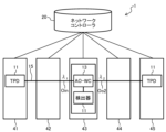
- FIG. 10 is a diagram showing an example of the configuration of an optical transmission system 1 including an all-optical wavelength conversion unit 13.
- the optical transmission system 1 includes five optical transmission devices 41, 42, 43, 44, and 45, and a network controller 20.
- the five optical transmission devices 41 to 45 are arranged in a line, for example, at locations spaced apart from each other by a certain distance.
- the optical transmission devices 41 to 45 are connected in series to each other via a single optical fiber cable 15 used as a transmission path for optical signals.
- the network controller 20 manages the entire optical communication network, which is made up of the optical transmission devices 41 to 45 and the optical fiber cable 15. For example, if any fault occurs on the optical communication network, the network controller 20 can generate information that is useful for identifying the location of the fault.
- optical transmission device 41 when transmitting data from optical transmission device 41 at one end of this communication network to optical transmission device 45 at the other end, optical transmission device 41 becomes the transmitting node and optical transmission device 45 becomes the receiving node.
- optical transmission devices 42 to 44 between these transmitting and receiving nodes are each used as relay nodes.
- the optical transmission device 41 of the sending node converts the data to be transmitted from an electrical signal to an optical signal of a specified wavelength inside the transponder 11, and sends this optical signal to the optical fiber cable 15.
- the optical transmission device 45 of the receiving node receives the optical signal from the optical fiber cable 15, and converts the optical signal to an electrical signal in the transponder 11 inside the optical transmission device 45 to obtain the received data.
- an optical transmission device 43 used as one relay node is equipped with an all-optical wavelength conversion unit 13 that implements the function of AO-WC (All Optical Wavelength Conversion).
- the all-optical wavelength conversion unit 13 in the optical transmission device 43 converts the wavelength of the input optical signal Oin with a wavelength of ⁇ 1 input from the optical fiber cable 15 to the optical transmission device 43 while it is still an optical signal, generates an optical signal with a wavelength of ⁇ 2 different from the input, and can send it to the downstream optical fiber cable 15 as an outgoing optical signal Oo2 with a wavelength of ⁇ 2.
- the all-optical wavelength conversion unit 13 shown in FIG. 10 can extract unnecessary optical components other than the optical main signal relayed inside the optical transmission device 43 and input them to the detector 11A in the optical transmission device 43.
- the detector 11A has the function of electrical termination processing like the transponder 11, but does not have the function of sending optical signals. In other words, the detector 11A has the function of converting the input optical signal into an electrical signal and the function of processing this electrical signal to detect transmission quality data.
- the optical transmission device 43 relays the main optical signal to be relayed as an optical signal without electrical termination and sends it to the downstream optical fiber cable 15, preventing an increase in delay due to relay processing. Also, as described below, there is no need to use an optical splitter to extract the optical signal input to the detector 11A, preventing a decrease in the optical intensity of the main optical signal.
- the all-optical wavelength conversion unit 13 extracts unnecessary optical components separate from the main optical signal being relayed and inputs them to the detector 11A in the optical transmission device 43, so that the detector 11A can detect transmission quality data at the node position of the optical transmission device 43.
- the network controller 20 can therefore obtain transmission quality data for relay nodes such as the optical transmission device 43 that does not perform electrical termination processing. For example, if a fault occurs, the network controller 20 can determine whether or not a fault has occurred for each section based on the transmission quality data at the position of each relay node.
- FIG. 11 is a diagram showing an example of the configuration of the all-optical wavelength conversion unit 13 included in the optical transmission system 1 of FIG.
- the all-optical wavelength conversion unit 13 includes a pumping light source 14, an optical fiber 15A, an optical multiplexer 16, a nonlinear optical medium 17, an optical demultiplexer 18, and an optical fiber 15B.
- the all-optical wavelength conversion unit 13 is an all-optical wavelength conversion device including a nonlinear optical medium 17 onto which both the optical main signal to be relayed and the pumping light emitted from the pumping light source 14 can be simultaneously incident.
- the pumping light source 14 generates pumping light Oe with a predetermined wavelength ⁇ e.
- the pumping light Oe generated by the pumping light source 14 passes through the optical fiber 15A and enters the optical multiplexer 16.
- the wavelength ⁇ e of the pumping light Oe is different from the wavelength ⁇ 1 of the input optical signal Oin.
- the optical intensity of the pumping light Oe is sufficiently greater than that of the input optical signal Oin.
- the optical multiplexer 16 generates light by multiplexing the input optical signal Oin input from the optical fiber cable 15 and the excitation light Oe input from the optical fiber 15A, and sends it to the input end of the nonlinear optical medium 17.
- the nonlinear optical medium 17 has nonlinear optical properties and can generate an optical signal with a wavelength different from that of the incident light.
- any one of highly nonlinear fiber (HNLF), periodically poled lithium niobate (PPLN), and a semiconductor optical amplifier (SOA) can be used as the nonlinear optical medium 17.
- the optical splitter 18 is connected to the light output side of the nonlinear optical medium 17, which is an all-optical wavelength conversion device.
- the output light Oout output from the output end of the nonlinear optical medium 17 is input to the optical splitter 18.
- the optical splitter 18 splits the incident light using its wavelength selection characteristics and extracts two types of optical signals. That is, the outgoing optical signal Oo2 with wavelength ⁇ 2 and the output light Oo1 with wavelength ⁇ 1 are output from different output terminals of the optical splitter 18.
- the wavelength ⁇ 2 of the outgoing optical signal Oo2 is generated based on the wavelength of the input optical signal Oin, the wavelength ⁇ e of the pump light Oe, and the nonlinear optical characteristics of the nonlinear optical medium 17.
- the input optical signal Oin with wavelength ⁇ 1 passes through the nonlinear optical medium 17 together with the pump light Oe, generating the wavelength ⁇ 2 of the wavelength-converted outgoing optical signal Oo2.
- the light emitted from the nonlinear optical medium 17 also contains an optical component with the same wavelength ⁇ 1 as before the wavelength conversion.
- the outgoing optical signal Oo2 with wavelength ⁇ 2 output from the optical splitter 18 is sent as a relay output from the output of the optical transmission device 43 to the downstream optical fiber cable 15.
- the outgoing light Oo1 with wavelength ⁇ 1 output from the optical splitter 18 is input to the detector 11A in the optical transmission device 43 via the optical fiber 15B.
- the wavelength of the optical main signal relayed by the optical transmission device 43 can be converted from ⁇ 1 to ⁇ 2 without electrical termination processing, preventing an increase in delay.
- the output light Oo1 of the same wavelength ⁇ 1 as before the wavelength conversion output from the all-optical wavelength conversion unit 13, i.e., unnecessary optical components other than the main signal can be input to the detector 11A.
- the detector 11A internally converts the input output light Oo1 of wavelength ⁇ 1 into an electrical signal, and various processes can be performed in the form of an electrical signal. This allows transmission quality data at the relay node position of the optical transmission device 43 to be obtained.
- the wavelength ⁇ 2 of the optical main signal sent by the relay node is different from the wavelength ⁇ 1 of the light other than the main signal input to detector 11A. Therefore, the correlation between the transmission quality detected for wavelength ⁇ 1 and the transmission quality detected for wavelength ⁇ 2 is specified in advance, and the transmission quality data detected by detector 11A is converted into transmission quality data of the optical signal to be relayed based on the correlation. This conversion process may be performed inside detector 11A or on the network controller 20 side.
- the optical transmission system 1 shown in FIG. 10 provides a method for detecting an optical signal generated in the AO-WC of the optical node device before or after wavelength conversion.
- peripheral devices optical attenuators and optical amplifiers
- the present invention was made in light of this background, and it is an object of the present invention to provide an optical transmission device and an optical transmission method that are capable of autonomously adjusting the output light intensity.
- an optical transmission device that can be installed in at least one optical relay node of an optical transmission system in which an optical transmitting node capable of transmitting an optical signal and an optical receiving node capable of receiving an optical signal are connected via an optical transmission path and one or more optical relay nodes are connected to an intermediate position of the optical transmission path, is characterized in that the optical transmission device comprises an input optical intensity adjustment unit that adjusts the optical intensity of a transmission wavelength signal input to the optical relay node, a wavelength conversion unit that converts the wavelength of the transmission wavelength signal whose optical intensity has been adjusted by the input optical intensity adjustment unit, a wavelength separation unit that separates the relayed transmission wavelength signal into the transmission wavelength signal having the same wavelength as before the wavelength conversion and a monitoring wavelength signal other than the transmission wavelength signal, an output optical intensity adjustment unit that adjusts the optical intensity of the transmission wavelength signal separated by the wavelength separation unit, a measurement unit that measures the transmission quality of the monitoring wavelength signal separated by the wavelength separation unit, and a control unit that controls the input optical intensity adjustment unit, the wavelength separation unit,
- the present invention makes it possible to realize an optical transmission device and an optical transmission method capable of autonomously adjusting the output light intensity.
- FIG. 1 is a schematic configuration diagram of an optical transmission device according to an embodiment of the present invention.
- FIG. 2 is a detailed configuration diagram of an optical transmission device according to an embodiment of the present invention.
- 1 is a detailed configuration diagram of an optical transmission device according to an embodiment of the present invention in which an optical amplifier is arranged.
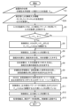
- 11 is a flowchart showing an operation of outputting signal light wavelength-converted by a WSS of an optical transmission device according to an embodiment of the present invention to ports ⁇ 2> to ⁇ n>.
- 1 is a configuration example in which signal light wavelength-converted by a WSS in an optical transmission device according to an embodiment of the present invention is output to a port ⁇ 1>.
- FIG. 11 is a flowchart illustrating an operation of outputting signal light wavelength-converted by a WSS of an optical transmission device according to an embodiment of the present invention to a port ⁇ 1>.
- FIG. 1 is a block diagram showing an example of the configuration of a typical optical transmission system.
- FIG. 1 is a block diagram showing an example of the configuration of a typical optical transmission system.
- FIG. 1 is a schematic diagram illustrating an example of the relationship between optical communication links and wavelength bands in multi-band networking technology.
- 1 is a block diagram showing an example of the configuration of an optical transmission system according to an embodiment of the present invention.
- 11 is a block diagram showing an example of the configuration of an all-optical wavelength conversion unit included in the optical transmission system of FIG. 10 .
- FIG. 1 is a schematic diagram of an optical transmission device according to an embodiment of the present invention.
- the optical transmission device according to this embodiment is applicable to the optical transmission system 1 in Fig. 10.
- the same components as those in Fig. 11 are denoted by the same reference numerals.
- the optical transmission device 100 is a transmission quality monitoring device that can be installed in at least one optical relay node of an optical transmission system 1 (Fig. 10) in which an optical transmitting node capable of transmitting an optical signal and an optical receiving node capable of receiving an optical signal are connected via an optical transmission path, and one or more optical relay nodes are connected to intermediate positions of the optical transmission path.
- the optical transmission device 100 includes a control unit 110, an optical input terminal 101, an optical output terminal 102, an input light intensity monitor 120 (input light intensity adjustment unit), a wavelength conversion unit 130, a wavelength selective switch (WSS) 140 (wavelength separation unit), a monitor measuring device 150 (measurement unit), and an output light intensity monitor 160 (output light intensity adjustment unit).
- a control unit 110 an optical input terminal 101, an optical output terminal 102, an input light intensity monitor 120 (input light intensity adjustment unit), a wavelength conversion unit 130, a wavelength selective switch (WSS) 140 (wavelength separation unit), a monitor measuring device 150 (measurement unit), and an output light intensity monitor 160 (output light intensity adjustment unit).
- WSS wavelength selective switch
- the input optical power monitor 120 adjusts the optical power of the transmission wavelength signal input to the optical relay node. Specifically, the input optical power monitor 120 adjusts the input optical power so that the appropriate optical power is input to the wavelength conversion unit 130.
- the wavelength conversion unit 130 converts the wavelength of the transmission wavelength signal whose optical intensity has been adjusted by the input optical intensity monitor 120.
- the wavelength conversion unit 130 also generates a monitoring wavelength signal from the transmission wavelength signal.
- the wavelength selective switch (WSS) 140 separates the relayed transmission wavelength signal into a transmission wavelength signal having the same wavelength as before the wavelength conversion and a monitoring wavelength signal (monitoring signal light) other than the transmission wavelength signal.
- the monitor measuring instrument 150 measures the signal quality of the monitoring wavelength signal.
- the output light intensity monitor 160 adjusts the light intensity of the transmission wavelength signal separated by the WSS 140.
- the output light intensity monitor 160 also adjusts the output light intensity of the wavelength conversion unit 130.
- Fig. 2 is a detailed configuration diagram of the optical transmission device 100 in Fig. 1.
- Fig. 2 shows a configuration example in which signal light wavelength-converted by the WSS 140 is output to ports ⁇ 2> to ⁇ n>.
- the control unit 110 sets the maximum input light intensity to the nonlinear optical medium 131, closes the input side optical shutter 124 before the input side optical power meter 122 starts measuring the input light intensity, controls the input side optical shutter 124 so that the input light intensity measured by the input side optical power meter 122 is equal to or less than the maximum input light intensity, and opens the input side optical shutter 124 after the input side optical power monitor 120 has completed adjustment.
- control unit 110 closes the output side optical shutter 164 to start measuring the output light intensity with the output side optical power meter 162, controls the output light intensity monitor 160 so that the output light intensity measured by the output side optical power meter 162 becomes the specified output light intensity, and opens the output side optical shutter 164 after adjustment by the output side optical power monitor 160 is completed.
- an input light intensity monitor 120 adjusts the input light intensity so that the input light is input to a wavelength conversion section 130 at an appropriate light intensity.
- the input light intensity monitor 120 includes a VOA (Variable Optical Attenuator) 121 , an input side optical power meter 122 , a beam splitter 123 , and an input side optical shutter 124 .
- VOA Very Optical Attenuator
- the VOA 121 variably attenuates the intensity of the optically transmitted optical signal upon receiving an instruction from the control unit 110 (receiving a control signal/voltage control signal from the control unit 110, the same applies below).
- the VOA 121 performs power management within the input optical power monitor 120 by voltage control from the control unit 110.
- the VOA 121 corresponds to wavelengths of, for example, C band, L band, and C+L band (FIG. 9).
- the input side optical power meter 122 measures the intensity (power) of light.
- the input side optical power meter 122 measures the output of the wavelength light source in the input optical power monitor 120 here.
- Beam splitter 123 splits an optical signal from one input channel into two or more optical signals.
- beam splitter 123 splits the optical signal from VOA 121 connected to optical input terminal 101 port ⁇ 1> into an optical signal output to wavelength conversion unit 130 and an optical signal output to input side optical power meter 122. Note that the wavelength and power remain unchanged after splitting by beam splitter 123.
- the input-side optical shutter 124 performs high-speed optical shutter control (control to transmit light only at specified times and block light at other times) using voltage control from the control unit 110.
- the input-side optical shutter 124 prevents light from entering the wavelength conversion unit 130 at the light intensity before adjustment is completed.
- the wavelength conversion unit 130 is a wavelength signal duplication functional unit that generates a monitoring wavelength signal (supervisory signal light) from a transmission wavelength signal.
- the wavelength conversion section 130 includes a nonlinear optical medium 131 , a pumping light source 132 , and an optical multiplexer 133 .
- the wavelength conversion section 130 is an all-optical wavelength conversion device including a nonlinear optical medium 131 onto which both the optical main signal to be relayed and the pumping light emitted from a pumping light source 132 can be simultaneously incident.
- the pumping light source 132 receives instructions from the control unit 110 and generates pumping light Oe of a predetermined wavelength ⁇ e.
- the pumping light Oe generated by the pumping light source 132 passes through the optical fiber 15A and enters the optical multiplexer 133.
- the wavelength ⁇ e of the pumping light Oe is different from the wavelength ⁇ 1 of the input optical signal Oin.
- the optical intensity of the pumping light Oe is sufficiently greater than that of the input optical signal Oin.
- the nonlinear optical medium 131 has nonlinear optical properties and can generate an optical signal with a wavelength different from that of the incident light.
- any one of highly nonlinear fiber (HNLF), periodically poled lithium niobate (PPLN), and a semiconductor optical amplifier (SOA) can be used as the nonlinear optical medium 131.
- HNLF highly nonlinear fiber
- PPLN periodically poled lithium niobate
- SOA semiconductor optical amplifier
- the WSS 140 is connected to the light output side of the nonlinear optical medium 131, which is an all-optical wavelength conversion device.
- the WSS 140 includes an optical demultiplexer (not shown), which receives instructions from the control unit 110, demultiplexes the incident light using wavelength selection characteristics, and extracts two types of optical signals.
- the WSS 140 outputs an output optical signal Oo2 with a wavelength ⁇ 2 and an output light Oo1 with a wavelength ⁇ 1 from a plurality of mutually different ports ⁇ 1>, ⁇ 2>, ..., ⁇ n>.
- the wavelength ⁇ 2 of the outgoing optical signal Oo2 is generated based on the wavelength of the input optical signal Oin, the wavelength ⁇ e of the pump light Oe, and the nonlinear optical characteristics of the nonlinear optical medium 131.
- the input optical signal Oin with wavelength ⁇ 1 passes through the nonlinear optical medium 131 together with the pump light Oe, generating the wavelength ⁇ 2 of the wavelength-converted outgoing optical signal Oo2.
- the outgoing light from the nonlinear optical medium 131 also contains an optical component with the same wavelength ⁇ 1 as before the wavelength conversion.
- the outgoing optical signal Oo2 with wavelength ⁇ 2 output from WSS 140 is sent as a relay output from the output of the optical transmission device 100 to the downstream optical fiber cable 15.
- the outgoing light Oo1 with wavelength ⁇ 1 output from WSS 140 is input to the monitor measuring instrument 150 via optical fiber 15B.
- the monitoring measuring instrument 150 measures the signal quality of the monitoring wavelength signal (monitoring signal light).
- the monitor measuring instrument 150 is a receiver 151 (more specifically, a detector provided in the receiver) of the optical transmission device 100 (hereinafter, this detector will be referred to as the receiver 151).
- the receiver 151 corresponds to, for example, the receiving section of a transponder (TPD). Like a transponder, it has an electrical termination function, but does not have the function of transmitting an optical signal.
- the receiver 151 has a function of converting an input optical signal into an electrical signal, and a function of processing this electrical signal to detect transmission quality data.
- the receiver equivalent to the transponder receiving section converts unnecessary light into an electrical signal and processes it to obtain transmission quality data.
- the receiver 151 may also be a spectrum analyzer, a polarization monitor, or a power meter.
- a spectrum analyzer is an electrical measuring instrument that displays a two-dimensional graph on a screen with frequency on the horizontal axis and power or voltage on the vertical axis. In the case of a spectrum analyzer, the signal-to-noise ratio is obtained. In the case of a polarization monitor, the polarization state of the optical signal is obtained, and in the case of a power meter, the optical intensity is obtained.
- the monitor measuring device 150 measures the signal light that is output to ports ⁇ 2>, ..., ⁇ n> and wavelength-converted by the WSS.
- a receiver 151 may be provided for each port ⁇ 2>, ..., ⁇ n>, or may be shared for multiple ports. Also, the receiver 151 may be a combination of multiple types of measuring devices.
- the output optical intensity monitor 160 includes a VOA 161 , an output-side optical power meter 162 , a beam splitter 163 , and an output-side optical shutter 164 .
- the VOA 161 variably attenuates the intensity of the optically transmitted optical signal under instructions from the control unit 110.
- the VOA 161 performs power management within the output optical power monitor 160 by voltage control from the control unit 110.
- the output side optical power meter 162 measures the intensity (power) of the light incident on the output optical power monitor 160 .
- the beam splitter 163 splits an optical signal from one input channel into two or more optical signals.
- the beam splitter 163 splits the optical signal from the VOA 161 connected to the port ⁇ 1> into an optical signal output to the optical output terminal 102 and an optical signal output to the output side optical power meter 162.
- the output-side optical shutter 164 performs high-speed optical shutter control under voltage control from the control unit 110.
- the output-side optical shutter 164 prevents light from being output to the outside at the light intensity before adjustment is completed.
- the optical transmission device 100 shown in FIG. 3 adds an optical amplifier 171 to the output side of the input light power monitor 120 (before the wavelength conversion unit 130) to amplify the output light of the input light power monitor 120.
- the optical transmission device 100 adds an optical amplifier 171 to amplify the output light of the nonlinear optical medium 131. Note that only one of the optical amplifier 171 on the output side of the input light power monitor 120 and the optical amplifier 171 on the output side of the nonlinear optical medium 131 may be placed according to the above conversion efficiency/gain.
- step S3 the input light intensity monitor 120 measures the input light intensity Pin using the input side optical power meter 122.
- step S4 the control unit 110 determines whether the measured input light intensity Pin is greater than a preset maximum input light intensity Pmax (Pin>Pmax).
- the maximum input light intensity Pmax to the nonlinear optical medium 131 is set in advance.
- step S6 the control unit 110 opens the input-side optical shutter 124 of the input light intensity monitor 120.
- the input light signals Oin of each component of wavelengths ⁇ 1 to ⁇ n (hereinafter simply referred to as input light signals of wavelengths ⁇ 1 to ⁇ n) are input from the input light intensity monitor 120 to the optical multiplexer 133 of the wavelength conversion unit 130 through the optical fiber cable 15.
- the wavelength of the input light signal Oin in Figure 2 is not a single wavelength, the above white waveforms are written in a rectangular shape (the same applies to the method of writing wavelength-converted signal light described below).
- step S7 the pump light source 14 generates pump light Oe with a single wavelength ⁇ e, and inputs the pump light Oe with wavelength ⁇ e to the optical multiplexer 133 via the optical fiber 15A.
- step S8 the optical multiplexer 133 multiplexes the input optical signal Oin of wavelengths ⁇ 1 to ⁇ n from the input optical intensity monitor 120 with the pumping light Oe from the pumping light source 14, and inputs the multiplexed signal to the nonlinear optical medium 131. Note that the optical intensity of the pumping light Oe is sufficiently greater than that of the input optical signal Oin.
- the nonlinear optical medium 131 of the wavelength conversion unit 130 passes both the input optical signal Oin of wavelengths ⁇ 1 to ⁇ n and the pump light Oe of wavelength ⁇ e, and generates signal light Oo2 obtained by wavelength-converting the input optical signal Oin of wavelengths ⁇ 1 to ⁇ n, with mirror symmetry around the pump light Oe as the center wavelength, based on the nonlinear optical characteristics of the nonlinear optical medium 131.
- the nonlinear optical medium 131 also outputs the wavelength-converted signal light Oo2 and the optical component Oo1 of wavelengths ⁇ 1 to ⁇ n that are the same as those before the wavelength conversion.
- the output light Oout of the nonlinear optical medium 131 also contains the wavelength-converted signal light Oo2 (see the hatched waveform indicated above the arrow of the output light Oout in FIG. 2) and the optical component Oo1 of wavelengths ⁇ 1 to ⁇ n that are the same as those before the wavelength conversion (see the outlined waveform indicated above the arrow of the output light Oout in FIG. 2).
- the output light Oout emitted from the nonlinear optical medium 131 contains optical components Oo1 with wavelengths ⁇ 1 to ⁇ n, a wavelength ⁇ e, and wavelength-converted signal light Oo2.
- the wavelength-converted signal light Oo2 is a component generated by wavelength conversion of the input optical signal Oin as it passes through the nonlinear optical medium 131.
- the optical intensity of the wavelength-converted signal light Oo2 component contained in the output light Oout depends on the nonlinear optical medium and the excitation light intensity, and can be made equivalent to that of the input optical signal Oin. For this reason, wavelength conversion can be performed without attenuating the optical intensity.
- optical intensity of the optical component Oo1 of wavelengths ⁇ 1 to ⁇ n contained in the output light Oout is equivalent to that of the input optical signal Oin. Therefore, optical signals other than the main signal with the same wavelengths ⁇ 1 to ⁇ n as before the wavelength conversion can be extracted from the output of the nonlinear optical medium 131 with sufficiently high optical intensity.
- step S10 the WSS140 transmits the wavelength-converted signal light Oo2 to ports ⁇ 2> through ⁇ n> as a monitoring signal light, and transmits the outgoing optical signal Oo1 to port ⁇ 1> of the monitor channel.
- step S11 the control unit 110 adjusts the output optical signal Oo1 to Pout at the VOA 161 while measuring it with the output optical power meter 162 (the output optical shutter 164 is closed).
- step S12 the control unit 110 opens the output side optical shutter 164 of the output light intensity monitor 160.
- each receiver 151 of the monitor measuring instrument 150 measures the transmission quality of the monitoring signal light Oo2 transmitted to ports ⁇ 2> to ⁇ n>, obtains the measurement data, and transmits the measurement data to the control unit 110, thereby completing the processing of this flow.
- a supervisory optical signal Oo2 having a sufficiently high optical intensity is input to each receiver 151, each receiver 151 can easily detect the transmission quality data at the position of the corresponding relay node.
- the above flow procedure makes it possible to adjust the output light intensity. It is also possible to make the output light intensity the same as the input light intensity.
- FIG. 5 shows an example of a configuration in which the signal light wavelength-converted by the WSS 140 is output to a port ⁇ 1>.
- the same components as those in FIG. 2 are denoted by the same reference numerals.
- Fig. 6 is a flowchart showing an operation of outputting the signal light wavelength-converted by the WSS of the optical transmission device 100 shown in Fig. 5 to the port ⁇ 1>.
- the same processing parts as those in Fig. 4 are assigned the same reference numerals, and the description of the overlapping parts will be omitted.
- Step S2A replaces step S2 in Figure 4.
- the operator sets the pre-input information (the wavelength setting of the channel to be monitored, and the output optical power Pout).
- the wavelength setting of the channel to be monitored is set so that the signal light wavelength-converted by the WSS is output to port ⁇ 1>.
- Step S10A replaces step S10 in FIG. 4.
- the WSS 140 transmits the wavelength-converted signal light Oo2 to port ⁇ 1> as the outgoing optical signal Oo1, and transmits the outgoing optical signal Oo2 of the same wavelengths ⁇ 1 to ⁇ n as before the wavelength conversion to ports ⁇ 2> to ⁇ n> of the monitor channel as the monitoring signal light.
- the above flow procedure makes it possible to adjust the output light intensity. It is also possible to make the output light intensity the same as the input light intensity.
- the device can be used as both a monitoring device and a wavelength converter.
- the optical transmission device 100 (FIGS. 1, 2, 3, and 5) can be installed in at least one optical relay node of the optical transmission system 1 (FIG. 10) in which an optical transmitting node capable of transmitting an optical signal and an optical receiving node capable of receiving an optical signal are connected via an optical transmission line, and one or more optical relay nodes are connected to intermediate positions of the optical transmission line.
- the optical transmission device 100 includes an input optical intensity adjuster (input optical intensity monitor 120) that adjusts the optical intensity of a transmission wavelength signal input to the optical relay node, and a wavelength converter that converts the wavelength of the transmission wavelength signal whose optical intensity has been adjusted by the input optical intensity adjuster.
- the wavelength conversion unit 130 converting the wavelength of the transmission wavelength signal into a wavelength signal having the same wavelength as that before the wavelength conversion
- a wavelength separation unit WSS 140
- WSS 140 separating the transmission wavelength signal to be relayed into a transmission wavelength signal having the same wavelength as that before the wavelength conversion and a monitoring wavelength signal other than the transmission wavelength signal
- an output light intensity adjustment unit output light intensity monitor 160
- a measurement unit monitoring measurement instrument 150 measuring the transmission quality of the monitoring wavelength signal separated by the wavelength separation unit
- a control unit 110 controlling the input light intensity adjustment unit, the wavelength separation unit, and the output light intensity adjustment unit.
- the input light intensity adjustment unit (input light intensity monitor 120) can suppress the deterioration of transmission quality by appropriately adjusting the input light intensity.
- the wavelength conversion unit 130 generates a monitoring wavelength signal from the transmission wavelength signal.
- the output light intensity adjustment unit (output light intensity monitor 160) appropriately outputs the light intensity of the output transmission wavelength signal.
- the measurement unit (monitoring measurement device 150) measures the transmission quality of the monitoring wavelength signal.
- Each of these functional units is controlled by the control unit 110. Therefore, it is possible to realize a transmission quality monitoring device that can autonomously adjust the output light intensity.
- the optical transmission device 100 can minimize the deterioration of the transmission performance of the transmission wavelength signal, or eliminate the need to readjust the optical level diagram. As a result, it is possible to introduce the device with minimal impact on existing optical transmission devices.
- the optical transmission device 100 relays the relayed transmission wavelength signal as an optical signal without electrical termination and sends it to the downstream optical fiber cable 15, preventing an increase in delay due to relay processing.
- the control unit 110 can obtain transmission quality data of relay nodes such as optical transmission devices that do not perform electrical termination processing. For example, if a failure occurs, the control unit 110 can determine whether or not a failure has occurred for each section based on the transmission quality data at the position of each relay node.
- the optical transmission device 100 can also switch the transmission wavelength signal and the wavelength-converted signal light by having the control unit 110 set each port ⁇ 1>, ⁇ 2>, ..., ⁇ n> of the WSS 140.
- the optical transmission device 100 transmits each optical component of wavelengths ⁇ 1 to ⁇ n, detects each optical component of the wavelength-converted signal light as a monitoring wavelength signal, and acquires transmission quality data ( Figures 2, 3, and 4).
- the optical transmission device 100 also transmits each optical component of wavelengths ⁇ 1 to ⁇ n, detects each optical component of wavelengths ⁇ 1 to ⁇ n as an extracted signal, and acquires transmission quality data ( Figures 5 and 6).
- the optical transmission device 100 can acquire transmission quality data even when wavelength conversion is not performed. In other words, since the light after wavelength conversion is used as the transmission signal light, it can be used as both a monitoring device and a wavelength converter.
- the optical transmission device 100 (Figs. 1, 2, 3, 5) includes an excitation light source 132 (Figs. 2, 3, 5) that emits excitation light of a wavelength different from the wavelength before wavelength conversion of the transmission wavelength signal to be relayed, and the wavelength conversion unit 130 is a nonlinear optical medium 131 (Figs. 2, 3, 5) into which both the transmission wavelength signal to be relayed and the excitation light emitted from the excitation light source 132 can be simultaneously incident, and the wavelength separation unit (WSS 140) separates the light emitted from the nonlinear optical medium 131 into an optical component with a wavelength after wavelength conversion and an optical component with a wavelength before wavelength conversion.
- WSS 140 wavelength separation unit
- the optical intensity of the wavelength-converted signal light components contained in the output light Oout from the nonlinear optical medium 131 depends on the nonlinear optical medium 131 and the pump light intensity, and can be made equivalent to the input optical signal Oin. Therefore, wavelength conversion can be performed without attenuating the optical intensity. Furthermore, the optical intensity of the optical components of wavelengths ⁇ 1 to ⁇ n contained in the output light Oout is equivalent to that of the input optical signal Oin. Therefore, optical signals other than the main signal with the same wavelengths ⁇ 1 to ⁇ n as before the wavelength conversion can be extracted from the output of the nonlinear optical medium 131 with sufficiently large optical intensity.
- the input light intensity adjustment unit (input light intensity monitor 120) is characterized by having an input side light shutter 124 (Figs. 2, 3, 5) that blocks the input of the transmission wavelength signal so that the transmission wavelength signal is not input to the wavelength conversion unit 130 at the light intensity before adjustment is completed, and the output light intensity adjustment unit (output light intensity monitor 160) is characterized by having an output side light shutter 164 (Figs. 2, 3, 5) that blocks the output of the transmission wavelength signal so that the transmission wavelength signal is not output at the light intensity before adjustment is completed.
- the input light intensity monitor 120 and the output light intensity monitor 160 have the input side optical shutter 124 and the output side optical shutter 164, and can perform input light intensity adjustment and output light intensity adjustment in an environment where the optical transmission path is temporarily closed to prevent unnecessary input and output ( Figures 4 and 6).
- the input light intensity adjustment unit (input light intensity monitor 120) includes an input side adjustment unit (VOA 121) (Figs. 2, 3, 5) that adjusts the input light intensity to the nonlinear optical medium 131, an input side optical power meter 122 (Figs. 2, 3, 5) that measures the input light intensity, and an input side optical shutter 124 (Figs. 2, 3, 5) that blocks the input of the transmission wavelength signal.
- the control unit 110 (Figs.
- the output light intensity adjustment unit (output light intensity monitor 160) includes an output side adjustment unit (VOA 161) (Figs. 2, 3, 5) that adjusts the amount of light output so that the output light intensity becomes a predetermined output light intensity, an output side optical power meter 162 that measures the output light intensity, and an output side optical shutter 164 that blocks the output of the transmission wavelength signal.
- the control unit 110 closes the output side optical shutter 164 before the output side optical power meter 162 starts measuring the output light intensity, controls the output side adjustment unit so that the output light intensity measured by the output side optical power meter 162 becomes the predetermined output light intensity, and opens the output side optical shutter 164 after adjustment by the output adjustment unit is completed.
- the optical transmission device 100 (Figs. 1, 2, 3, and 5) is characterized in that an optical amplifier 171 (Fig. 3) that amplifies the signal light is disposed on the output side of the input light intensity adjustment unit (input light intensity monitor 120) and/or on the output side of the wavelength separation unit (WSS 140).
- an optical amplifier 171 (Fig. 3) that amplifies the signal light is disposed on the output side of the input light intensity adjustment unit (input light intensity monitor 120) and/or on the output side of the wavelength separation unit (WSS 140).
- the optical amplifier 171 By doing this, by arranging the optical amplifier 171 on the output side of the input light intensity monitor 120, it is possible to amplify the input light when the input light intensity is low. Also, by arranging the optical amplifier 171 immediately after the output from the WSS 140, it is possible to amplify the output light when the gain/conversion efficiency of the nonlinear optical medium 131 is low.
- the network controller 20 ( Figure 10) of the optical transmission system 1, it is generally assumed that the "Pre-FEC BER" is used as the transmission quality data detected by the transponder 11 of each optical relay node. Meanwhile, the detector 11A and the transponder 11 can obtain data such as the amount of chromatic dispersion compensation, polarization mode dispersion, and polarization dependent loss in addition to the "Pre-FEC BER" by electrical signal processing of the communication data. Therefore, the network controller 20 can collect data such as the amount of chromatic dispersion compensation, polarization mode dispersion, and polarization dependent loss from each optical relay node that implements the detector 11A or the transponder 11, and use this data as learning data for machine learning. This helps to realize failure prediction in optical networks without electrical termination processing.
- each of the above configurations, functions, processing units, processing means, etc. may be realized in hardware, for example by designing some or all of them as an integrated circuit.
- each of the above configurations, functions, etc. may be realized by software that causes a processor to interpret and execute a program that realizes each function.
- Information on the programs, tables, files, etc. that realize each function can be stored in a memory, a recording device such as a hard disk or SSD (Solid State Drive), or a recording medium such as an IC (Integrated Circuit) card, SD (Secure Digital) card, or optical disc.
Landscapes
- Physics & Mathematics (AREA)
- Electromagnetism (AREA)
- Engineering & Computer Science (AREA)
- Computer Networks & Wireless Communication (AREA)
- Signal Processing (AREA)
- Optical Communication System (AREA)
Abstract
Un dispositif de transmission optique (100) comprend : un dispositif de surveillance d'intensité lumineuse d'entrée (120) qui règle l'intensité lumineuse d'un signal de longueur d'onde de transmission entré dans un nœud relais optique; une unité de conversion de longueur d'onde (130) qui convertit la longueur d'onde d'un signal de longueur d'onde de transmission obtenu à la suite du réglage de l'intensité lumineuse par une unité de réglage d'intensité lumineuse d'entrée; un WSS (140) qui divise un signal de longueur d'onde de transmission à relayer en un signal de longueur d'onde de transmission présentant la même longueur d'onde que celle avant la conversion de longueur d'onde et un signal de longueur d'onde de surveillance autre que le signal de longueur d'onde de transmission; un dispositif de surveillance d'intensité lumineuse de sortie (160) qui règle l'intensité lumineuse du signal de longueur d'onde de transmission séparé par le WSS (140); un instrument de mesure de surveillance (150) qui mesure la qualité de transmission du signal de longueur d'onde de surveillance séparé par le WSS (140); et une unité de commande (110) qui commande le dispositif de surveillance d'intensité lumineuse d'entrée (120), le WSS (140) et le dispositif de surveillance d'intensité lumineuse de sortie (160).
Priority Applications (2)
| Application Number | Priority Date | Filing Date | Title |
|---|---|---|---|
| PCT/JP2023/020896 WO2024252500A1 (fr) | 2023-06-05 | 2023-06-05 | Dispositif de transmission optique et procédé de transmission optique |
| JP2025525474A JPWO2024252500A1 (fr) | 2023-06-05 | 2023-06-05 |
Applications Claiming Priority (1)
| Application Number | Priority Date | Filing Date | Title |
|---|---|---|---|
| PCT/JP2023/020896 WO2024252500A1 (fr) | 2023-06-05 | 2023-06-05 | Dispositif de transmission optique et procédé de transmission optique |
Publications (1)
| Publication Number | Publication Date |
|---|---|
| WO2024252500A1 true WO2024252500A1 (fr) | 2024-12-12 |
Family
ID=93795297
Family Applications (1)
| Application Number | Title | Priority Date | Filing Date |
|---|---|---|---|
| PCT/JP2023/020896 Ceased WO2024252500A1 (fr) | 2023-06-05 | 2023-06-05 | Dispositif de transmission optique et procédé de transmission optique |
Country Status (2)
| Country | Link |
|---|---|
| JP (1) | JPWO2024252500A1 (fr) |
| WO (1) | WO2024252500A1 (fr) |
Citations (3)
| Publication number | Priority date | Publication date | Assignee | Title |
|---|---|---|---|---|
| JPH0897771A (ja) * | 1994-09-27 | 1996-04-12 | Fujitsu Ltd | 光波長多重伝送方式 |
| JP2012249014A (ja) * | 2011-05-26 | 2012-12-13 | Fujitsu Ltd | 光信号処理装置および光通信システム |
| WO2021156932A1 (fr) * | 2020-02-04 | 2021-08-12 | 日本電信電話株式会社 | Dispositif de remplacement de bande de longueur d'onde cyclique, système de transmission multibande, et procédés de remplacement de bande de longueur d'onde cyclique |
-
2023
- 2023-06-05 WO PCT/JP2023/020896 patent/WO2024252500A1/fr not_active Ceased
- 2023-06-05 JP JP2025525474A patent/JPWO2024252500A1/ja active Pending
Patent Citations (3)
| Publication number | Priority date | Publication date | Assignee | Title |
|---|---|---|---|---|
| JPH0897771A (ja) * | 1994-09-27 | 1996-04-12 | Fujitsu Ltd | 光波長多重伝送方式 |
| JP2012249014A (ja) * | 2011-05-26 | 2012-12-13 | Fujitsu Ltd | 光信号処理装置および光通信システム |
| WO2021156932A1 (fr) * | 2020-02-04 | 2021-08-12 | 日本電信電話株式会社 | Dispositif de remplacement de bande de longueur d'onde cyclique, système de transmission multibande, et procédés de remplacement de bande de longueur d'onde cyclique |
Non-Patent Citations (1)
| Title |
|---|
| MINAMI HARUKA; HIROSE KENTA; FUKATANI TAKAFUMI; NAKAGAWA MASAHIRO; SEKI TAKESHI; SHIMIZU SHIMPEI; KOBAYASHI TAKAYUKI; KAZAMA TAKUS: "Experimental Demonstration of Cascadable PPLN-Based Inter-Band Wavelength Converters for Band-Switchable Multi-Band Optical Cross-Connect", 2023 OPTICAL FIBER COMMUNICATIONS CONFERENCE AND EXHIBITION (OFC), 5 March 2023 (2023-03-05), pages 1 - 3, XP034345578, DOI: 10.23919/OFC49934.2023.10117169 * |
Also Published As
| Publication number | Publication date |
|---|---|
| JPWO2024252500A1 (fr) | 2024-12-12 |
Similar Documents
| Publication | Publication Date | Title |
|---|---|---|
| JP3995781B2 (ja) | 波長選択フィルタを用いた光分岐・挿入装置及び光分岐装置 | |
| CN100483985C (zh) | 光终端站与操作光传输系统的方法 | |
| US10608775B2 (en) | Optical transmission apparatus, optical transmission method, and optical transmission system | |
| CN114124287B (zh) | 光信号控制方法及装置、光传输节点和光传输系统 | |
| US6559984B1 (en) | Apparatus for monitoring optical path based on the identification of optical cross-connect input ports | |
| US7831118B2 (en) | Coarse wavelength division multiplexing optical transmission system, and coarse wavelength division multiplexing optical transmission method | |
| US11115128B2 (en) | Optical transmission device, transmission system, and control method for transmission system | |
| EP2355388A2 (fr) | Réseau optique et son procédé de commande associé | |
| US20030058497A1 (en) | All-optical switching sites for an agile optical network | |
| US8098988B2 (en) | Optical add/drop multiplexer | |
| JPH11331127A (ja) | 波長分割多重システム、及びその端局 | |
| US11336386B2 (en) | Submarine branching apparatus, optical submarine cable system, and optical communication method | |
| US7627244B2 (en) | Optical transmission apparatus, continuity testing method therein, and optical transmission system | |
| US20090317078A1 (en) | Optical transmission device and optical transmission method | |
| US10567081B2 (en) | Transmission system and transmission method | |
| US20150086192A1 (en) | Determining method, determining optical module, and optical communication apparatus | |
| US7773884B2 (en) | Method and apparatus for automatic shut-down and start-up of optical amplifiers in optical networks | |
| JP6497439B2 (ja) | 通信装置、通信方法、及び、通信システム | |
| US7076163B2 (en) | Method and system for testing during operation of an open ring optical network | |
| JP5125080B2 (ja) | 光強度測定装置および光強度測定方法 | |
| EP1134925B1 (fr) | Système de transmission optique incluant l'optimisation des performances | |
| WO2024252500A1 (fr) | Dispositif de transmission optique et procédé de transmission optique | |
| WO2021229744A1 (fr) | Dispositif de détection de défaillance, procédé de détection de défaillance, et support d'enregistrement de programme de détection de défaillance | |
| JP2008503886A (ja) | 波長分割多重(wdm)光分波器 | |
| US20230208548A1 (en) | Optical transmission device |
Legal Events
| Date | Code | Title | Description |
|---|---|---|---|
| 121 | Ep: the epo has been informed by wipo that ep was designated in this application |
Ref document number: 23940607 Country of ref document: EP Kind code of ref document: A1 |
|
| ENP | Entry into the national phase |
Ref document number: 2025525474 Country of ref document: JP Kind code of ref document: A |
|
| WWE | Wipo information: entry into national phase |
Ref document number: 2025525474 Country of ref document: JP |
|
| NENP | Non-entry into the national phase |
Ref country code: DE |