WO2024252514A1 - Water purifier - Google Patents
Water purifier Download PDFInfo
- Publication number
- WO2024252514A1 WO2024252514A1 PCT/JP2023/020971 JP2023020971W WO2024252514A1 WO 2024252514 A1 WO2024252514 A1 WO 2024252514A1 JP 2023020971 W JP2023020971 W JP 2023020971W WO 2024252514 A1 WO2024252514 A1 WO 2024252514A1
- Authority
- WO
- WIPO (PCT)
- Prior art keywords
- water
- water purifier
- circumferential direction
- dial
- purifier body
- Prior art date
- Legal status (The legal status is an assumption and is not a legal conclusion. Google has not performed a legal analysis and makes no representation as to the accuracy of the status listed.)
- Ceased
Links
Images



Classifications
-
- C—CHEMISTRY; METALLURGY
- C02—TREATMENT OF WATER, WASTE WATER, SEWAGE, OR SLUDGE
- C02F—TREATMENT OF WATER, WASTE WATER, SEWAGE, OR SLUDGE
- C02F1/00—Treatment of water, waste water, or sewage
-
- C—CHEMISTRY; METALLURGY
- C02—TREATMENT OF WATER, WASTE WATER, SEWAGE, OR SLUDGE
- C02F—TREATMENT OF WATER, WASTE WATER, SEWAGE, OR SLUDGE
- C02F1/00—Treatment of water, waste water, or sewage
- C02F1/28—Treatment of water, waste water, or sewage by sorption
Definitions
- This disclosure relates to a water purifier.
- Water purifiers that purify supplied water include, for example, a water purification filter that is connected to a water faucet, and a prefilter that is placed on the water supply side of the water purification filter.
- the water purification filter mainly removes, for example, dissolved components from the water.
- the prefilter mainly removes, for example, solid components from the water.
- Patent Document 1 discloses a prefilter for a water purifier that uses a switching mechanism to selectively switch between multiple modes with different paths from the water inlet to the water outlet.
- the switching mechanism may, for example, be a dial that can rotate relative to the water purifier body.
- the water purifier body has the mode name written on the surface facing upward.
- the dial has an indicator on the surface facing upward. The desired mode can be selected by rotating the dial relative to the water purifier body and aligning the indicator with the mode name when viewed from above.
- the pipes connected to the water inlet and the pipes connected to the water outlet may be positioned in opposite directions.
- the mode name will be written on the front side as seen by the operator, but if the pipes connected to the water inlet are on the right side, the mode name will be written on the back side as seen by the operator. Even if the mode name is written on the back side, the operator can see it when looking from above, so they can easily operate the dial to switch modes.
- the mode name will be placed on the side. If the mode name is placed on the side, the operator will have to view the mode name horizontally. If the mode name is displayed on the back side, the operator will not be able to view the mode name horizontally, which is a problem.
- This disclosure has been made in consideration of the above points, and aims to provide a water purifier that can easily switch modes regardless of the position of the pipes connected to the water inlet and outlet.
- a first aspect of the present disclosure is a water purifier comprising: a water purifier body having a water inlet and a water outlet arranged at a distance from each other in the circumferential direction around a central axis; and a dial that is detachably attached to the water purifier body and can rotate in the circumferential direction relative to the water purifier body when attached to the water purifier body, and that can select from a plurality of modes in which water introduced from the water inlet is discharged through different paths depending on the circumferential position relative to the water purifier body, the dial having a plurality of markings on its outer circumferential surface that indicate information relating to the plurality of modes, one of the markings being attachable to the water purifier body at a first position away from the water inlet on one side in the circumferential direction and at a second position away from the water inlet on the other side in the circumferential direction.
- FIG. 2 is an exploded perspective view of the water purifier of the present disclosure.
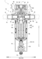
- FIG. 2 is a longitudinal sectional view of the water purifier of the present disclosure.
- FIG. FIG. FIG. FIG. FIG. FIG. 2 is a schematic vertical cross-sectional view of the water purifier of the present disclosure in a first mode.
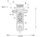
- FIG. 11 is a schematic vertical cross-sectional view of the water purifier of the present disclosure in a second mode.
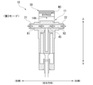
- FIG. 11 is a schematic vertical cross-sectional view of the water purifier of the present disclosure in a third mode.
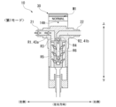
- FIG. 2 is a schematic vertical cross-sectional view of the water purifier of the present disclosure in a first mode.
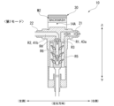
- FIG. 2 is a schematic vertical cross-sectional view of the water purifier of the present disclosure in a first mode.
- the water purifier 1 includes a water purifier main body 10 and a dial 30.
- the water purifier body 10 is cylindrical and extends vertically around a central axis J.
- the water purifier body 10 includes a valve seat 11, a valve body 12, a filter element 13, a first cover member 14, a second cover member 15, a third cover member 16, a switching member 17, and a drain handle 18.
- the valve seat 11 is formed of a metal material, for example.
- the valve seat 11 has a water inlet 21, a water outlet 22, a water passage R1, a water passage R2, and a fitting hole 23.
- a water supply pipe P1 is connected to the water inlet 21. Water enters the water inlet 21 via the pipe P1. For example, clean water enters the water inlet 21 via the pipe P1.
- a water outlet pipe P2 is connected to the water outlet 22.
- the water outlet 22 allows the water that has passed through the filter element 13, for example, to exit.
- the water passage R1 extends in a radial direction centered on the central axis J.
- the water passage R1 is arranged coaxially with the water inlet section 21. Water entering from the water inlet section 21 is introduced into the water passage R1.
- the water passage R2 extends in a radial direction centered on the central axis J.
- the water passage R2 is arranged coaxially with the water outlet section 22. Water passing through the water passage R2 is introduced into the water outlet section 22 and then flows out of the pipe P2.
- the water inlet section 21 and the water outlet section 22 are arranged circumferentially apart about the central axis J. As an example, the water inlet section 21 and the water outlet section 22 are arranged 180 degrees apart in the circumferential direction. As an example, the water passage R1 and the water passage R2 are arranged 180 degrees apart in the circumferential direction.
- the fitting hole 23 extends in the vertical direction about the central axis J. The radially inner ends of the water passage R1 and the water passage R2 open into the fitting hole 23.
- the water inlet section 21 and the water outlet section 22 are each provided with a direction indicator section 3 that indicates the water flow direction.
- the direction indicator section 3 may be provided on only one of the water inlet section 21 and the water outlet section 22.
- the direction indicator section 3 is provided on the front side and the back side of the water inlet section 21 and the water outlet section 22, respectively.
- the direction in which the water inlet section 21 and the water outlet section 22 are arranged with respect to the central axis J is referred to as the left-right direction
- the side in which the water inlet section 21 is arranged is referred to as the left side
- the side in which the water outlet section 22 is arranged is referred to as the right side.
- the direction perpendicular to the left-right direction and the up-down direction is referred to as the facing direction in which the worker faces.
- the facing direction when the water flow at the installation location is from left to right, the side facing the worker is referred to as the front side, and when the water flow is from right to left, the side facing the worker is referred to as the back side.
- the valve body 12 is formed of a resin material, for example.
- the outer peripheral surface 12a of the valve body 12 is fitted liquid-tightly into the fitting hole 23 in the valve seat 11 so as to be rotatable in the circumferential direction about the central axis J.
- the left-right position of the valve body 12 is the position in the first mode, which will be described later, used when removing solid components in the water that has entered through the water inlet 21.
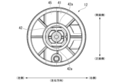
- the valve body 12 has a disk portion 41, a protrusion portion 42, an outer cylinder portion 43, an inner cylinder portion 44, and a through hole 45.
- the disk portion 41 is formed in a disk shape centered on the central axis J. As shown in Figures 4 and 5, the disk portion 41 has a protruding wall 41a that protrudes downward to the right of the central axis J.
- the protrusion 42 is formed in a cylindrical shape extending upward from the disk portion 41. As shown in FIG. 4, the protrusion 42 has flat surfaces 42a formed on both radial sides to prevent rotation. The flat surfaces 42a are parallel to each other.
- the outer tube portion 43 is formed in a cylindrical shape extending downward from the outer edge of the disc portion 41. To the right of the central axis J, the outer tube portion 43 extends downward from the outer edge of the protruding wall 41a.
- the inner tube portion 44 is formed in a cylindrical shape extending downward from the disc portion 41. The inner tube portion 44 is disposed radially inward and spaced apart from the outer tube portion 43. To the right of the central axis J, the inner tube portion 44 extends downward from the inner edge of the protruding wall 41a. Below the disc portion 41, the space between the outer tube portion 43 and the inner tube portion 44 forms a water passage R3. The internal space of the inner tube portion 44 forms a water passage R4 extending in the vertical direction.
- the outer tube portion 43 has a through hole 43a that penetrates in the left-right direction on the left side.
- the radially inner end of the through hole 43a opens into the water passage R3.
- the protruding wall 41a has a through hole 41b that penetrates in the left-right direction.
- the radially inner end of the through hole 41b opens into the water passage R4.
- the through hole 45 penetrates the valve body 12 in the opposing direction.
- the vertical position of the through hole 45 is a position that is included in the vertical range of the through holes 43a and 41b.
- the through hole 45 faces and communicates with the water passage R1 and the water passage R2.
- the switching member 17 is formed of a resin material, for example.
- the switching member 17 is attached to the upper side of the valve body 12.
- the switching member 17 has a disk portion 51, a first peripheral wall portion 52, a protrusion portion 53, a cylindrical portion 54, a cylindrical portion 55, and a rib portion 56.
- the disk portion 51 is formed in a disk shape centered on the central axis J.
- the first peripheral wall portion 52 is formed in a cylindrical shape extending upward from the outer edge of the disk portion 51.
- the protrusion 53 protrudes radially inward from the first peripheral wall portion 52 centered on the central axis J.
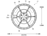
- the protrusion 53 is formed, for example, at the same height as the first peripheral wall portion 52. As shown in FIG. 6, one protrusion 53 is provided at the left side position.
- a protrusion indicator 53a is formed on the upper surface of the protrusion 53, which indicates that it is a protrusion 53 and the circumferential position where it is attached to the valve body 12. As an example, the protrusion indicator 53a is an arrow pointing radially outward.
- the cylindrical portion 54 extends downward from the disc portion 51 and is formed in a cylindrical shape with a bottom wall 54a at its lower end.
- the cylindrical portion 55 is tubular and extends downward from the bottom wall 54a with the central axis J as its center.
- the protrusion 42 of the valve body 12 fits into the inside of the cylindrical portion 55 from below around the entire circumference. With the protrusion 42 fitting into the inside of the cylindrical portion 55 around the entire circumference, the switching member 17 is fixed in a state where it is prevented from rotating relative to the valve body 12. As the switching member 17 rotates around the central axis J, the valve body 12 rotates in an integrated state.
- the rib portion 56 extends radially inward from the first peripheral wall portion 52.
- the rib portion 56 extends upward from the disk portion 51.
- the upper end of the rib portion 56 is located below the upper end of the first peripheral wall portion 52.
- the rib portion 56 is disposed at a position of 60 degrees and a position of 120 degrees in the counterclockwise direction corresponding to one side in the circumferential direction when viewed from the front.
- Two rib portions 56 are disposed at a pitch of 60 degrees on the front side in the opposing direction.
- the rib portions 56 are respectively arranged at 60 degrees and 120 degrees in the clockwise direction corresponding to the other side in the circumferential direction when viewed from the front. Two rib portions 56 are arranged on the back side in the opposing direction. Two rib portions 56 are arranged at a pitch of 60 degrees on the back side in the opposing direction.
- the filter element 13 is disposed below the valve seat 11 and the valve body 12.
- the filter element 13 has a housing 13A, a filter 13B, and a drainage section 13C.
- the housing 13A is formed, for example, from a resin material.
- the housing 13A is formed in a cylindrical shape extending in the vertical direction.
- the housing 13A is open at the upper end.
- the housing 13A has a male thread at the upper end, and is fixed to the valve seat 11 from below by being screwed into a female thread formed in the valve seat 11.
- the upper end of the housing 13A is formed with a diameter larger than the diameter of the fitting hole 23.
- Filter 13B extends vertically around central axis J. Filter 13B is disposed inside housing 13A and radially spaced from housing 13A. The space between housing 13A and filter 13B forms water passage R5. The internal space of filter 13B forms water passage R6.
- the upper end of filter 13B fits liquid-tight from below into inner tube portion 44 of valve body 12.
- water passage R6 communicates with water passage R4.
- the lower end of filter 13B is connected to the lower end of housing 13A and drainage portion 13C.
- the drainage section 13C is connected to the filter 13B from below.
- the drainage section 13C has a drainage channel 13d that extends vertically around the central axis J.
- the drainage channel 13d is connected to the water passage R5.
- a drainage pipe P3 can be connected to the lower end of the drainage section 13C. Water drained from the drainage channel 13d is discharged via the pipe P3.
- the drain handle 18 is positioned on the side facing the operator when the water flow at the installation location is from left to right.
- the drain handle 18 is positioned radially outward of the drain channel 13d.
- the drain handle 18 has a circular shape when viewed from the front.
- the drain handle 18 is rotatable about an axis that extends in the opposing direction. When rotated, the drain handle 18 can switch between opening and closing the drain channel 13d.
- the first cover member 14 is formed of a resin material, for example.
- the first cover member 14 is formed in a cylindrical shape that covers the upper side of the water purifier main body 10 from the radial outside.
- the first cover member 14 covers the periphery of the valve seat 11 and the valve body 12 from the radial outside while leaving the upper side of the switching member 17 exposed.
- the outer diameter of the first cover member 14 and the outer diameter of the dial 30 are the same.
- the water inlet section 21 and the water outlet section 22 are provided to protrude radially outward from the first cover member 14.
- the first cover member 14 has an indicator portion 14A located near the upper end on the outer circumferential surface. If the center position of the water inlet portion 21 in the circumferential direction is taken as 0 degrees, the indicator portion 14A is located at a position 90 degrees counterclockwise corresponding to one side in the circumferential direction when viewed from the front, and at a position 90 degrees clockwise corresponding to the other side in the circumferential direction. As an example, the indicator portion 14A is formed in a dot shape.
- the second cover member 15 is formed, for example, from a resin material.
- the second cover member 15 is formed in a cylindrical shape that covers the lower side of the first cover member 14 in the water purifier body 10 from the outside in the radial direction.
- the second cover member 15 covers the periphery of the filter element 13 from the outside in the radial direction.
- the outer diameter of the second cover member 15 is the same as the outer diameter of the first cover member 14.
- the third cover member 16 is formed, for example, from a resin material.
- the third cover member 16 is formed in a cylindrical shape that covers the lower side of the second cover member 15 in the water purifier body 10 from the outside in the radial direction.
- the third cover member 16 covers the periphery of the drainage section 13C from the outside in the radial direction.
- the outer diameter of the third cover member 16 and the outer diameter of the second cover member 15 are the same.
- the outer diameter of the dial 30, the outer diameter of the first cover member 14, the outer diameter of the second cover member 15, and the outer diameter of the third cover member 16 are the same.
- the dial 30 is detachably attached to the water purifier body 10.
- the dial 30 is detachably attached to the switching member 17.
- the dial 30 can rotate circumferentially relative to the water purifier body 10.
- the dial 30 can select from a number of modes in which water introduced from the water inlet 21 flows out through different routes depending on the circumferential position relative to the water purifier body 10.
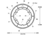
- the dial 30 has a top wall portion 31, a side wall portion 32, a second peripheral wall portion 33, a recess 34, a second recess 35, a third recess 36, and an engagement portion 37.
- the top wall portion 31 is formed in a disk shape located at the top of the dial 30.
- the side wall portion 32 is formed in a cylindrical shape extending downward from the outer edge of the top wall portion 31.
- the side wall portion 32 has a knurled portion 32a on the upper side of the outer circumferential surface.
- the knurled portion 32a is formed around the entire circumference.
- the side wall 32 has markings M1, M2, and M3 below the knurled portion 32a on the outer circumferential surface.
- the markings M1, M2, and M3 indicate information about a number of modes in which water introduced from the water inlet 21 exits through different paths. Details of the markings M1, M2, and M3 will be described later.
- the second peripheral wall portion 33 extends downward from the top wall portion 31 of the dial 30.
- the second peripheral wall portion 33 extends in the circumferential direction centered on the central axis J.
- the radial position of the second peripheral wall portion 33 is a position where it overlaps with the protrusion 53 and the rib portion 56 of the switching member 17 in the direction along the central axis J.
- the position of the lower end of the second peripheral wall portion 33 is a position that is lower than the upper ends of the protrusion 53 and the rib portion 56 when the dial 30 is attached to the switching member 17.
- the position of the lower end of the second peripheral wall portion 33 is a position where it interferes with the protrusion 53 and the rib portion 56 when the dial 30 is attached to the switching member 17 without being aligned in the circumferential direction.
- the recess 34 is formed in the second peripheral wall portion 33.
- the recess 34 has a shape in which the second peripheral wall portion 33 is locally missing.
- the recess 34 is disposed in a radial position where it overlaps with the protrusion 53 in the direction along the central axis J when the dial 30 is attached to the switching member 17.
- the recess 34 is disposed at a position of 0 degrees and a position of 180 degrees.
- the circumferential dimension of the recess 34 is larger than the circumferential dimension of the protrusion 53. The recess 34 can fit into the protrusion 53 when the dial 30 is attached to the switching member 17.
- the dial 30 can be attached to the switching member 17 in a first position where the protrusion 53 fits when the recess 34 is at 0 degrees in the circumferential direction, and in a second position where the protrusion 53 fits when the recess 34 is rotated 180 degrees in the circumferential direction and the recess 34 is at 180 degrees in the circumferential direction.
- the second recess 35 is formed in the second peripheral wall portion 33.
- the second recess 35 has a shape in which the second peripheral wall portion 33 is locally missing. If the center position of the protrusion 53 on the switching member 17 in the circumferential direction is set to 0 degrees, the second recess 35 is disposed at a position of 60 degrees and a position of 120 degrees on the rear side. When the dial 30 is attached to the switching member 17, the second recess 35 is disposed at a radial position where it overlaps with the rib portion 56 in the direction along the central axis J. The circumferential dimension of the second recess 35 is greater than the circumferential dimension of the rib portion 56.
- the dial 30 is shifted circumferentially from the first and second positions where the protrusions 53 fit into the recesses 34 relative to the switching member 17, the second peripheral wall portion 33 and the rib portion 56 interfere with each other in the direction along the central axis J.
- the dial 30 is attached to the switching member 17 in the first and second circumferential positions where the protrusions 53 fit into the recesses 34 relative to the switching member 17, the rib portion 56 can fit into the second recess 35 without interfering with each other in the direction along the central axis J.
- the third recess 36 is formed in the second peripheral wall 33.
- the third recess 36 is formed in a shape in which the second peripheral wall 33 is locally missing.
- the third recess 36 is formed in a range exceeding 60 degrees in the circumferential direction, centered on a position 90 degrees toward the front side, assuming that the center position of the protrusion 53 in the switching member 17 in the circumferential direction is 0 degrees.
- the rib portion 56 can fit into the third recess 36 without interference in the direction along the central axis J when the dial 30 is attached to the switching member 17 at either the first or second circumferential position where the protrusion 53 fits into the recess 34.
- the engaging portion 37 extends downward from the top wall portion 31 at a position radially outward from the first peripheral wall portion 52 of the switching member 17.
- the engaging portion 37 has a claw portion 37a at its lower end that protrudes radially inward.
- the engaging portion 37 is a snap fit.
- the dial 30 is attached to the switching member 17 at either the first or second circumferential position, the claw portion 37a of the engaging portion 37 engages with the lower end of the disc portion 51 of the switching member 17 from below.
- Two engaging portions 37 are arranged facing each other in the radial direction.
- the engaging portions 37 are arranged at 0 degrees and 180 degrees in the circumferential direction, assuming that the center position of the protrusion 53 of the switching member 17 is 0 degrees.
- the two engaging portions 37 engage with the lower end of the disc portion 51 of the switching member 17 from below at the claw portion 37a, so that the dial 30 is held in the switching member 17 in a direction along the central axis J.
- Notation M1 is positioned at 90 degrees counterclockwise in a plan view, corresponding to one side in the circumferential direction, assuming that the left side, which is the center position of the water inlet section 21 in the circumferential direction, is 0 degrees.
- Notation M1 is positioned on the front side of the outer circumferential surface of side wall section 32.
- Notation M1 is positioned on the side where the water flow at the installation location is from left to right when dial 30 is attached to switching member 17 in the first circumferential position.
- the notation of notation M1 corresponds to the first mode in which water introduced from water inlet section 21 is discharged through the first path, as shown in Figure 8.
- the first mode is set when the dial 30 and the switching member 17 are rotated and the notation M1 is aligned using the indicator portion 14A as an indicator.
- the first mode is the mode when the valve body 12 is rotated to a position where the through hole 43a in the valve body 12 faces and communicates with the water passage R1, and the through hole 41b faces and communicates with the water passage R2.
- the first path in the first mode is a path along which water introduced from the water inlet 21 passes through water passage R1, through hole 43a, water passage R3, water passage R5, water passage R6, water passage R4, through hole 41b, water passage R2, and the water outlet 22 before being discharged from the pipe P2.
- the first mode is a normal mode in which solid components in the water introduced from the water inlet 21 are removed by the filter 13B and then purified water is discharged, and is shown as "NORMAL" in the notation M1 as an example.
- the notation M2 is positioned at a position 90 degrees clockwise, which corresponds to the other side in the circumferential direction in a plan view.
- Notation M2 is positioned on the rear side of the outer circumferential surface of side wall section 32.
- Notation M2 is positioned on the rear side when dial 30 is attached to switching member 17 in the first circumferential position.
- the notation of notation M2 corresponds to the second mode in which water introduced from the water inlet section 21 is drained through the second path, as shown in Figure 9.
- the second mode is set when the dial 30 and the switching member 17 are rotated and the notation M2 is aligned with the index portion 14A as an index.
- the second mode is the mode when the valve body 12 is rotated to a position where the through hole 43a in the valve body 12 faces and communicates with the water passage R2, and the through hole 41b faces and communicates with the water passage R1.
- the second path in the second mode is a path in which water introduced from the water inlet 21 travels through water passage R2, through hole 41b, water passage R4, water passage R6, water passage R5, and drainage passage 13d before being drained from pipe P3.
- drainage handle 18 is rotated to open drainage passage 13d.
- the second mode is a backwash mode in which the introduced water is caused to flow from the inside to the outside of filter 13B, thereby discharging solid components that have been removed from the water in filter element 13 and remain, and is shown as "BACKWASH" in notation M2 as an example.
- Notation M3 is positioned at 0 degrees in a plan view, with the left side being the center position of the water inlet section 21 in the circumferential direction, being 0 degrees. Notation M3 is positioned on the left side of the outer peripheral surface of side wall section 32. Notation M3 is positioned on the left side when dial 30 is attached to switching member 17 in the first circumferential position. The notation of notation M3 corresponds to the third mode in which water introduced from water inlet section 21 is discharged through a third route, as shown in FIG. 10.
- the third mode is set when the dial 30 and the switching member 17 are rotated and the notation M3 is aligned with the index portion 14A as an index.
- the third mode is set when the valve body 12 is rotated to a position where the through hole 45 in the valve body 12 faces and communicates with the water passages R1 and R2.
- the third path in the third mode is a path through which water introduced from the water inlet 21 flows through the water passage R1, the through hole 45, the water passage R2, and the water outlet 22 before flowing out from the pipe P2.
- the third path is a path through which water introduced from the water inlet 21 does not pass through the filter element 13.
- water can flow out from the pipe P2 when the filter element 13 is removed from the water purifier body 10 for cleaning.
- the third mode is a bypass mode that allows water introduced from the water inlet 21 to flow through the water outlet 22.
- the third mode is indicated in the notation M3 as "BYPASS.”
- the "NORMAL" marking M1 is located on the front side. The operator can easily see that the water purifier 1 is in normal mode.
- the water purifier 1 may have the water supply pipe P1 connected to the water inlet 21 on the right side.
- the water purifier 1 is set to normal mode, but the indicator 14A and the "BACKWASH" marking M2 indicating the second mode are located on the front side.
- the operator moves the claws 37a radially outward by pulling the dial 30 upward, releasing the dial 30 from the switching member 17.
- the operator removes the dial 30 from the switching member 17 and then rotates it 180 degrees.
- the operator attaches the dial 30 to the switching member 17 at a circumferential position where the recess 34 fits into the protrusion 53 in the second position.
- the "NORMAL" marking M1 which corresponds to the actual mode of the water purifier 1, is located on the front side.
- the notation part M1 can be attached to the water purifier body 10 at a first position away from the water inlet part 21 on one side in the circumferential direction, and at a second position away from the water inlet part 21 on the other side in the circumferential direction, so that the mode can be easily switched regardless of the positions of the pipes P1 and P2 connected to the water inlet part 21 and the water outlet part 22.
- the outer diameter of the water purifier body 10 and the outer diameter of the dial 30 are the same, which improves the aesthetic appearance.
- the dial 30 is attached to the upper side of the water purifier body 10, making it easier to grip when switching modes and improving operability.
- the water purifier body 10 is a prefilter having a filter 13B that removes solid components from the water, but the configuration is not limited to this.
- the water purifier may also have a water purification filter that is disposed downstream of the prefilter and removes dissolved components from the water.
- the present disclosure includes the following aspects:
- a water purifier comprising: a water purifier body having a water inlet and a water outlet arranged at a distance from each other in the circumferential direction around a central axis; and a dial that is detachably attached to the water purifier body and can rotate in the circumferential direction relative to the water purifier body when attached to the water purifier body, and that can select from a plurality of modes in which water introduced from the water inlet is discharged through different paths depending on the circumferential position relative to the water purifier body, the dial having a plurality of markings on its outer circumferential surface that indicate information relating to the plurality of modes, one of the markings being attachable to the water purifier body at a first position that is away from the water inlet on one side in the circumferential direction and a second position that is away from the water inlet on the other side in the circumferential direction.
Landscapes
- Life Sciences & Earth Sciences (AREA)
- Hydrology & Water Resources (AREA)
- Engineering & Computer Science (AREA)
- Environmental & Geological Engineering (AREA)
- Water Supply & Treatment (AREA)
- Chemical & Material Sciences (AREA)
- Organic Chemistry (AREA)
- Water Treatment By Sorption (AREA)
Abstract
Description
本開示は、浄水器に関する。 This disclosure relates to a water purifier.
給水された水を浄水する浄水器としては、例えば、水栓に接続される浄水フィルター、及び浄水フィルターの給水側に配置されるプレフィルターが挙げられる。浄水フィルターは主として、例えば、水中の溶存成分を除去する。プレフィルターは主として、例えば、水中の固形成分を除去する。 Water purifiers that purify supplied water include, for example, a water purification filter that is connected to a water faucet, and a prefilter that is placed on the water supply side of the water purification filter. The water purification filter mainly removes, for example, dissolved components from the water. The prefilter mainly removes, for example, solid components from the water.
特許文献1には、浄水器として、入水部から出水部へ至る経路が異なる複数のモードに対して、切替機構を用いて選択的に切り換えるプレフィルターが開示されている。
切替機構としては、例えば、浄水器本体に対して回転可能なダイアルが用いられる。浄水器本体には、上側を向く面にモード名が記載される。ダイアルには、上側を向く面に指標が設けられる。浄水器本体に対してダイアルを回転させ、上側から見た状態で指標をモード名が記載された位置とすることによって、所望のモードを選択することができる。 The switching mechanism may, for example, be a dial that can rotate relative to the water purifier body. The water purifier body has the mode name written on the surface facing upward. The dial has an indicator on the surface facing upward. The desired mode can be selected by rotating the dial relative to the water purifier body and aligning the indicator with the mode name when viewed from above.
浄水器は、設置箇所によって入水部に接続される配管と、出水部に接続される配管の位置が左右逆方向になる場合がある。例えば、入水部に接続される配管が左側にある場合に作業者から見て正面側に記載されたモード名は、入水部に接続される配管が右側にある場合に作業者から見て背面側に記載される。モード名が背面側に記載された場合においても、作業者は上側から見た状態で視認できるため、支障なくダイアルを操作してモードを切り替えることができる。 Depending on where the water purifier is installed, the pipes connected to the water inlet and the pipes connected to the water outlet may be positioned in opposite directions. For example, if the pipes connected to the water inlet are on the left side, the mode name will be written on the front side as seen by the operator, but if the pipes connected to the water inlet are on the right side, the mode name will be written on the back side as seen by the operator. Even if the mode name is written on the back side, the operator can see it when looking from above, so they can easily operate the dial to switch modes.
美的外観性を向上させるためにダイアルの外径と浄水器本体の外径を同一にすると、モード名は側面に配置される。モード名が側面に配置された場合、作業者は水平方向にモード名を視認することになる。モード名が背面側に表示された場合、作業者は、水平方向にモード名を視認することができないという問題が生じる。 If the outer diameter of the dial and the outer diameter of the water purifier body are made the same to improve the aesthetic appearance, the mode name will be placed on the side. If the mode name is placed on the side, the operator will have to view the mode name horizontally. If the mode name is displayed on the back side, the operator will not be able to view the mode name horizontally, which is a problem.
本開示は、以上のような点を考慮してなされたもので、入水部及び出水部に接続される配管の位置に依らず、モードを容易に切り替えることができる浄水器を提供することを目的とする。 This disclosure has been made in consideration of the above points, and aims to provide a water purifier that can easily switch modes regardless of the position of the pipes connected to the water inlet and outlet.
本開示の第1の態様は、中心軸を中心とする周方向に離れて配置された入水部及び出水部を有する浄水器本体と、前記浄水器本体に対して着脱可能に設けられ、前記浄水器本体に装着されたときに前記浄水器本体に対して前記周方向に回転可能であり、前記浄水器本体に対する前記周方向の位置に応じて前記入水部から導入された水が異なる経路で出水される複数のモードから選択可能なダイアルと、を備え、前記ダイアルは、外周面に前記複数のモードに関する情報を表記する複数の表記部を有し、前記表記部の1つが、前記入水部から前記周方向の一方側に離れた第1位置と、前記入水部から前記周方向の他方側に離れた第2位置とにおいて前記浄水器本体に装着可能である、浄水器である。 A first aspect of the present disclosure is a water purifier comprising: a water purifier body having a water inlet and a water outlet arranged at a distance from each other in the circumferential direction around a central axis; and a dial that is detachably attached to the water purifier body and can rotate in the circumferential direction relative to the water purifier body when attached to the water purifier body, and that can select from a plurality of modes in which water introduced from the water inlet is discharged through different paths depending on the circumferential position relative to the water purifier body, the dial having a plurality of markings on its outer circumferential surface that indicate information relating to the plurality of modes, one of the markings being attachable to the water purifier body at a first position away from the water inlet on one side in the circumferential direction and at a second position away from the water inlet on the other side in the circumferential direction.
以下、本開示の浄水器の実施の形態を、図1から図12を参照して説明する。以下の実施形態は、本開示の一態様を示すものであり、この開示を限定するものではなく、本開示の技術的思想の範囲内で任意に変更可能である。また、以下の図面においては、各構成をわかりやすくするために、実際の構造と各構造における縮尺等を異ならせている。 Below, an embodiment of the water purifier of the present disclosure will be described with reference to Figures 1 to 12. The following embodiment shows one aspect of the present disclosure, does not limit the disclosure, and can be modified as desired within the scope of the technical ideas of the present disclosure. In addition, in the following drawings, the scale of each structure is different from the actual structure in order to make each configuration easier to understand.
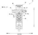
図1に示すように、浄水器1は、浄水器本体10と、ダイアル30と、を備えている。
As shown in FIG. 1, the
図1及び図2に示すように、浄水器本体10は、中心軸Jを中心として上下方向に延びる円柱状である。浄水器本体10は、弁座11と、弁体12と、フィルターエレメント13と、第1カバー部材14と、第2カバー部材15と、第3カバー部材16と、切替部材17と、排水ハンドル18と、を備える。
As shown in Figures 1 and 2, the
弁座11は、一例として金属材料で形成されている。弁座11は、入水部21と、出水部22と、通水路R1と、通水路R2と、嵌合孔23と、を有する。入水部21には、給水用の配管P1が接続される。入水部21には、配管P1を介して水が入水する。入水部21には、配管P1を介して、例えば、上水が入水する。出水部22には、出水用の配管P2が接続される。出水部22は、例えば、フィルターエレメント13に通水された水を出水させる。
The
通水路R1は、中心軸Jを中心とする径方向に延びる。通水路R1は、入水部21と同軸で配置されている。入水部21から入水した水は、通水路R1に導入される。通水路R2は、中心軸Jを中心とする径方向に延びる。通水路R2は、出水部22と同軸で配置されている。通水路R2を通水された水は、出水部22に導入された後に配管P2から出水される。
The water passage R1 extends in a radial direction centered on the central axis J. The water passage R1 is arranged coaxially with the
入水部21及び出水部22は、中心軸Jを中心とする周方向に離れて配置されている。入水部21及び出水部22は、一例として、周方向に180度離れて配置されている。通水路R1及び通水路R2は、一例として、周方向に180度離れて配置されている。嵌合孔23は、中心軸Jを中心として上下方向に延びる。嵌合孔23には、通水路R1及び通水路R2の径方向内側の端部が開口している。入水部21及び出水部22には、それぞれ水の流れ方向を示す方向指標部3が設けられている。方向指標部3は、入水部21及び出水部22の何れか一方だけに設けられてもよい。方向指標部3は、入水部21及び出水部22における正面側及び背面側にそれぞれ設けられている。
The
入水部21及び出水部22が方向指標部3を有することによって、給水用の配管P1及び出水用の配管P2を入水部21の出水部22のどちらに接続するかを容易に判断することができる。
By having the
以下では、中心軸Jに対して入水部21及び出水部22が配置される方向を左右方向と呼び、入水部21が配置される側を左側と呼び、出水部22が配置される側を右側と呼ぶ。左右方向及び上下方向と直交する方向を作業者が対向する対向方向と呼ぶ。対向方向において、設置場所の水の流れが左から右の場合に作業者と対向する側を正面側、右から左の場合に作業者と対向する側を背面側と呼ぶ。
In the following, the direction in which the
弁体12は、一例として、樹脂材で形成されている。弁体12は、外周面12aにおいて弁座11における嵌合孔23に中心軸Jを中心とする周方向に回転可能に液密に嵌め合わされる。以下では、弁体12における左右方向の位置は、入水部21から入水した水中の固形成分を除去する際に用いられる後述する第1モードにおける位置である。
The
図3に示すように、弁体12は、円板部41と、突起部42と、外筒部43と、内筒部44と、貫通孔45と、を有する。
As shown in FIG. 3, the
円板部41は、中心軸Jを中心とする円板状に形成されている。図4及び図5に示すように、円板部41は、中心軸Jよりも右側において、下側に突出する突出壁41aを有する。
The
突起部42は、円板部41から上側に延びる円柱状に形成されている。図4に示すように、突起部42は、径方向の両側に回り止めとなる平面部42aがそれぞれ形成されている。平面部42aは互いに平行である。
The
外筒部43は、円板部41の外縁から下側に延びる円筒状に形成されている。中心軸Jよりも右側において、外筒部43は、突出壁41aの外縁から下側に延びる。内筒部44は、円板部41から下側に延びる円筒状に形成されている。内筒部44は、外筒部43の径方向内側に離れて配置されている。中心軸Jよりも右側において、内筒部44は、突出壁41aの内縁から下側に延びる。円板部41よりも下側において、外筒部43と内筒部44との間の空間は、通水路R3を形成する。内筒部44の内部空間は、上下方向に延びる通水路R4を形成している。
The
外筒部43は、左側の位置に左右方向に貫通する貫通孔43aを有する。貫通孔43aにおける径方向内側の端部は、通水路R3に開口している。突出壁41aは、左右方向に貫通する貫通孔41bを有する。貫通孔41bにおける径方向内側の端部は、通水路R4に開口している。
The
貫通孔45は、弁体12を対向方向に貫通する。貫通孔45の上下方向の位置は、貫通孔43a及び貫通孔41bの上下方向の範囲に含まれる位置である。貫通孔45が左右方向に延びる位置に弁体12が回転したときに、貫通孔45は、通水路R1及び通水路R2と対向して連通する。
The through
切替部材17は、一例として、樹脂材で形成されている。切替部材17は、弁体12の上側に装着されている。切替部材17は、円板部51と、第1周壁部52と、突部53と、円筒部54と、円筒部55と、リブ部56と、を有する。
The switching
円板部51は、中心軸Jを中心とする円板状に形成されている。第1周壁部52は、円板部51の外縁から上側に延びる円筒状に形成されている。突部53は、第1周壁部52から中心軸Jを中心とする径方向の内側に突出する。突部53は、例えば、第1周壁部52と同じ高さに形成されている。図6に示すように、突部53は、左側の位置に一つ設けられている。突部53の上面には、突部53であること及び弁体12に対して装着される周方向の位置を示す突部指標53aが形成されている。突部指標53aは、一例として、径方向の外側を向く矢印である。
The
円筒部54は、円板部51から下側に延び、下端に底壁54aを有する円筒状に形成されている。円筒部55は、中心軸Jを中心として底壁54aから下側に延びる筒状である。円筒部55の内部には、弁体12における突起部42が下側から全周に亘って嵌まり合っている。円筒部55の内部に突起部42が全周に亘って嵌まり合うことによって、切替部材17は、弁体12に対して回り止めされた状態で固定される。切替部材17が中心軸Jを中心として回転することによって、弁体12が一体化された状態で回転する。
The
リブ部56は、第1周壁部52から径方向の内側に延びる。リブ部56は、円板部51から上側に延びる。リブ部56の上端は、第1周壁部52の上端よりも下側の位置である。
The
リブ部56は、周方向において突部53の中心位置を0度とすると、正面視において周方向の一方側に対応する反時計回り方向で60度の位置と、120度の位置にそれぞれ配置されている。リブ部56は、対向方向の正面側に60度のピッチで二つ配置されている。
If the center position of the
リブ部56は、周方向において突部53の中心位置を0度とすると、正面視において周方向の他方側に対応する時計回り方向で60度の位置と、120度の位置にそれぞれ配置されている。リブ部56は、対向方向の背面側に二つ配置されている。リブ部56は、対向方向の背面側に60度のピッチで二つ配置されている。
If the center position of the
フィルターエレメント13は、弁座11及び弁体12の下側に配置される。フィルターエレメント13は、ハウジング13Aと、フィルター13Bと、排水部13Cと、を有する。ハウジング13Aは、は、一例として、樹脂材で形成されている。ハウジング13Aは、上下方向に延びる円筒状に形成されている。ハウジング13Aは、上端において開口している。ハウジング13Aは、上端に雄ねじを有し、弁座11に形成された雌ねじにねじ込まれることによって、下側から弁座11に固定される。ハウジング13Aの上端は、嵌合孔23の直径よりも大きい直径で形成されている。
The
フィルター13Bは、中心軸Jを中心として上下方向に延びている。フィルター13Bは、ハウジング13Aの内部にハウジング13Aと径方向に離れて配置されている。ハウジング13Aとフィルター13Bとの間の空間は、通水路R5を形成している。フィルター13Bの内部空間は、通水路R6を形成している。
フィルター13Bの上端は、弁体12における内筒部44に下側から液密に嵌まり合っている。フィルター13Bの上端が弁体12における内筒部44に液密に嵌まり合うことによって、通水路R6は通水路R4と連通する。フィルター13Bの下端は、ハウジング13Aの下端と排水部13Cに連結されている。
The upper end of
排水部13Cは、下側からフィルター13Bに連結されている。排水部13Cは、中心軸Jを中心として上下方向に延びる排水路13dを有する。排水路13dは、通水路R5と連通している。排水部13Cの下端には、排水用の配管P3が接続可能である。排水路13dから排水される水は、配管P3を介して排出される。
The
排水ハンドル18は、設置場所の水の流れが左から右の場合に作業者と対向する側に配置されている。排水ハンドル18は、排水路13dの径方向外側に配置されている。排水ハンドル18は、正面視円形状である。排水ハンドル18は、対向方向に延びる軸線を中心として回転可能である。排水ハンドル18は、回転操作されたときに、排水路13dの開放と閉塞とを切り替え可能である。
The drain handle 18 is positioned on the side facing the operator when the water flow at the installation location is from left to right. The drain handle 18 is positioned radially outward of the
第1カバー部材14は、一例として、樹脂材で形成されている。第1カバー部材14は、浄水器本体10の上側を径方向の外側から覆う円筒状に形成されている。第1カバー部材14は、切替部材17の上側を露出させた状態で弁座11及び弁体12の周囲を径方向の外側から覆う。第1カバー部材14の外径と、ダイアル30の外径とは、同一である。入水部21及び出水部22は、第1カバー部材14から径方向の外側に突出して設けられている。
The
第1カバー部材14は、外周面における上端に近い位置に指標部14Aを有する。指標部14Aは、周方向において入水部21の中心位置を0度とすると、正面視において周方向の一方側に対応する反時計回り方向で90度の位置と、周方向の他方側に対応する時計回り方向で90度の位置とにそれぞれ配置されている。指標部14Aは、一例としてドット状に形成されている。
The
第2カバー部材15は、一例として、樹脂材で形成されている。第2カバー部材15は、浄水器本体10における第1カバー部材14より下側を径方向の外側から覆う円筒状に形成されている。第2カバー部材15は、フィルターエレメント13の周囲を径方向の外側から覆う。第2カバー部材15の外径と、第1カバー部材14の外径とは、同一である。
The
第3カバー部材16は、一例として、樹脂材で形成されている。第3カバー部材16は、浄水器本体10における第2カバー部材15より下側を径方向の外側から覆う円筒状に形成されている。第3カバー部材16は、排水部13Cの周囲を径方向の外側から覆う。第3カバー部材16の外径と、第2カバー部材15の外径とは、同一である。
The
ダイアル30の外径、第1カバー部材14の外径、第2カバー部材15の外径及び第3カバー部材16の外径は、同一である。ダイアル30、第1カバー部材14、第2カバー部材15及び第3カバー部材16の外径が同一であることによって、浄水器1の美的外観性を向上させることができる。
The outer diameter of the
ダイアル30は、浄水器本体10に対して着脱可能に設けられる。ダイアル30は、切替部材17に対して着脱可能に設けられる。ダイアル30は、浄水器本体10に装着されたときに浄水器本体10に対して周方向に回転可能である。ダイアル30は、浄水器本体10に対する周方向の位置に応じて入水部21から導入された水が異なる経路で出水される複数のモードから選択可能である。
The
ダイアル30は、図7に示すように、天壁部31と、側壁部32と、第2周壁部33と、凹部34と、第2凹部35と、第3凹部36と、係合部37と、を有する。
As shown in FIG. 7, the
天壁部31は、ダイアル30における頂部に位置する円板状に形成されている。側壁部32は、天壁部31の外縁から下側に延びる円筒状に形成されている。側壁部32は、外周面における上側にローレット部32aを有する。ローレット部32aは、全周に亘って形成されている。側壁部32の外周面にローレット部32aが形成されていることによって、ダイアル30を回転させるために外周面を手指又は工具等で掴んだ際の摩擦抵抗が大きくなり、回転させやすくなる。
The
側壁部32は、外周面におけるローレット部32aよりも下側に、表記部M1、M2、M3を有する。表記部M1、M2、M3は、それぞれ入水部21から導入された水が異なる経路で出水される複数のモードに関する情報を表記する。表記部M1、M2、M3の詳細については、後述する。
The
第2周壁部33は、ダイアル30における天壁部31から下側に延びる。第2周壁部33は、中心軸Jを中心として周方向に延びる。第2周壁部33の径方向の位置は、切替部材17における突部53及びリブ部56と中心軸Jに沿う方向で重なる位置である。第2周壁部33の下端の位置は、ダイアル30が切替部材17に装着されたときに、突部53及びリブ部56の上端よりも下側となる位置である。第2周壁部33の下端の位置は、ダイアル30が周方向で位置合わせされない状態で切替部材17に装着するときに、突部53及びリブ部56と干渉する位置である。
The second
凹部34は、第2周壁部33に形成されている。凹部34は、第2周壁部33を局所的に欠落させた形状である。凹部34は、ダイアル30が切替部材17に装着されたときに、突部53と中心軸Jに沿う方向で重なる径方向の位置に配置されている。凹部34は、周方向において切替部材17における突部53の中心位置を0度とすると、0度の位置と、180度の位置にそれぞれ配置されている。凹部34は、周方向の寸法が突部53の周方向の寸法よりも大きい。凹部34は、ダイアル30が切替部材17に装着されたときに、突部53が嵌まることができる。
The
凹部34が周方向において0度の位置と、180度の位置にそれぞれ配置されていることによって、ダイアル30は、凹部34が周方向において0度の位置において突部53が嵌まる第1位置と、180度回転して凹部34が周方向において180度の位置において突部53が嵌まる第2位置において、切替部材17に装着可能である。
By arranging the
第2凹部35は、第2周壁部33に形成されている。第2凹部35は、第2周壁部33を局所的に欠落させた形状である。第2凹部35は、周方向において切替部材17における突部53の中心位置を0度とすると、背面側に60度の位置と、120度の位置にそれぞれ配置されている。第2凹部35は、ダイアル30が切替部材17に装着されたときに、リブ部56と中心軸Jに沿う方向で重なる径方向の位置に配置されている。第2凹部35の周方向の寸法は、リブ部56の周方向の寸法よりも大きい。
The
ダイアル30が切替部材17に対して突部53が凹部34に嵌まる第1位置及び第2位置から周方向にずれた場合は、第2周壁部33とリブ部56が中心軸Jに沿う方向で干渉する。ダイアル30が切替部材17に対して突部53が凹部34に嵌まる周方向の第1位置及び第2位置においてダイアル30が切替部材17に装着されたときに、第2凹部35には、リブ部56が中心軸Jに沿う方向で干渉することなく嵌まることができる。
If the
第3凹部36は、第2周壁部33に形成されている。第3凹部36は、第2周壁部33を局所的に欠落させた形状に形成されている。第3凹部36は、周方向において切替部材17における突部53の中心位置を0度とすると正面側に90度の位置を中心として、周方向で60度を超える範囲に形成されている。ダイアル30が切替部材17に対して突部53が凹部34に嵌まる周方向の第1位置及び第2位置の何れか一方においてダイアル30が切替部材17に装着されたときに、ダイアル30が切替部材17に対して突部53が凹部34に嵌まる周方向の第1位置及び第2位置においてダイアル30が切替部材17に装着されたときに、第3凹部36には、リブ部56が中心軸Jに沿う方向で干渉することなく嵌まることができる。
The
係合部37は、切替部材17における第1周壁部52よりも径方向の外側の位置において天壁部31から下側に延びている。係合部37は、下端に径方向の内側に突出する爪部37aを有する。係合部37は、スナップフィットである。係合部37は、ダイアル30が切替部材17に対して周方向の第1位置及び第2位置の何れか一方に装着されたときに、爪部37aが切替部材17における円板部51の下端に下側から係合する。係合部37は、径方向に対向して2つ配置されている。係合部37は、周方向において切替部材17における突部53の中心位置を0度とすると、0度の位置と180度の位置に配置されている。2つの係合部37が爪部37aにおいて切替部材17における円板部51の下端に下側から係合することによって、ダイアル30は切替部材17に中心軸Jに沿う方向に保持される。
The engaging
表記部M1は、周方向において入水部21の中心位置である左側を0度とすると、平面視において周方向の一方側に対応する反時計回り方向で90度の位置に配置される。表記部M1は、側壁部32の外周面における正面側に配置されている。表記部M1は、ダイアル30が切替部材17に対して周方向の第1位置において装着されたときに、設置場所の水の流れが左から右となる側に配置される。表記部M1の表記は、図8に示すように、入水部21から導入された水が第1経路で出水される第1モードに対応する。
Notation M1 is positioned at 90 degrees counterclockwise in a plan view, corresponding to one side in the circumferential direction, assuming that the left side, which is the center position of the
第1モードは、ダイアル30及び切替部材17が回転して、指標部14Aを指標として表記部M1が位置合わせされたときに設定される。第1モードは、弁体12における貫通孔43aが通水路R1と対向して連通し、貫通孔41bが通水路R2と対向して連通する位置に弁体12が回転したときのモードである。
The first mode is set when the
第1モードにおける第1経路は、入水部21から導入された水が通水路R1、貫通孔43a、通水路R3、通水路R5、通水路R6、通水路R4、貫通孔41b、通水路R2及び出水部22を辿って配管P2から出水される経路である。第1モードは、入水部21から導入された水中の固形成分がフィルター13Bによって除去された後に浄水として出水されるノーマルモードであり、表記部M1には、一例として、「NORMAL」として表記される。
The first path in the first mode is a path along which water introduced from the
表記部M2は、周方向において入水部21の中心位置である左側を0度とすると、平面視において周方向の他方側に対応する時計回り方向で90度の位置に配置される。表記部M2は、側壁部32の外周面における背面側に配置されている。表記部M2は、ダイアル30が切替部材17に対して周方向の第1位置において装着されたときに、背面側に配置される。表記部M2の表記は、図9に示すように、入水部21から導入された水が第2経路で排水される第2モードに対応する。
If the left side, which is the center position of the
第2モードは、ダイアル30及び切替部材17が回転して、指標部14Aを指標として表記部M2が位置合わせされたときに設定される。第2モードは、弁体12における貫通孔43aが通水路R2と対向して連通し、貫通孔41bが通水路R1と対向して連通する位置に弁体12が回転したときのモードである。
The second mode is set when the
第2モードにおける第2経路は、入水部21から導入された水が通水路R2、貫通孔41b、通水路R4、通水路R6、通水路R5及び排水路13dを辿って配管P3から排水される経路である。第2モードにおいては、排水ハンドル18を回転させて排水路13dを開放しておく。第2モードは、導入された水をフィルター13Bの内側から外側に水を流すことによって、フィルターエレメント13において水から除去されて残留する固形成分を排出するバックウォッシュモードであり、表記部M2には、一例として、「BACKWASH」として表記される。
The second path in the second mode is a path in which water introduced from the
表記部M3は、周方向において入水部21の中心位置である左側を0度とすると、平面視において0度の位置に配置される。表記部M3は、側壁部32の外周面における左側に配置されている。表記部M3は、ダイアル30が切替部材17に対して周方向の第1位置において装着されたときに、左側に配置される。表記部M3の表記は、図10に示すように、入水部21から導入された水が第3経路で出水される第3モードに対応する。
Notation M3 is positioned at 0 degrees in a plan view, with the left side being the center position of the
第3モードは、ダイアル30及び切替部材17が回転して、指標部14Aを指標として表記部M3が位置合わせされたときに設定される。第3モードは、弁体12における貫通孔45が通水路R1及び通水路R2と対向して連通する位置に弁体12が回転したときのモードである。
The third mode is set when the
第3モードにおける第3経路は、入水部21から導入された水が通水路R1、貫通孔45、通水路R2及び出水部22を辿って配管P2から出水される経路である。第3経路は、入水部21から導入された水がフィルターエレメント13に通水されない経路である。第3モードにおいては、例えば、フィルターエレメント13を清掃のために浄水器本体10から取り外して状態で配管P2から出水可能である。第3モードは、入水部21から導入された水を出水部22に連通させるバイパスモードである。第3モードは、表記部M3には、一例として、「BYPASS」として表記される。
The third path in the third mode is a path through which water introduced from the
浄水器1が左側において、給水用の配管P1が入水部21に接続された場合、例えば、第1モードにおいては、表記部M1の「NORMAL」は正面側に位置する。作業者は、浄水器1のモードがノーマルモードであることを容易に視認できる。
When the
図11に示すように、浄水器1は、設置場所によっては、右側において、給水用の配管P1が入水部21に接続される。浄水器1が対向方向の向きを反転させ、右側において給水用の配管P1が入水部21に接続される場合、浄水器1はノーマルモードに設定されているが、正面側には、指標部14Aとともに、第2モードであることを示す「BACKWASH」の表記部M2が位置する。
As shown in FIG. 11, depending on the installation location, the
作業者は、ダイアル30を上側に引き上げることによって爪部37aを径方向の外側に移動させて、切替部材17によるダイアル30の保持を解除させる。作業者は、ダイアル30を切替部材17から取り外した後に180度回転させる。作業者は、凹部34が突部53に第2位置において嵌まる周方向の位置でダイアル30を切替部材17に装着させる。図12に示されるように、ダイアル30を切替部材17に第2位置において装着することによって、正面側には、浄水器1の実モードに対応した「NORMAL」の表記部M1が位置する。
The operator moves the
実施形態の浄水器1においては、表記部M1が、入水部21から周方向の一方側に離れた第1位置と、入水部21から周方向の他方側に離れた第2位置とにおいて浄水器本体10に装着可能であるため、入水部21及び出水部22に接続される配管P1及び配管P2の位置に依らずにモードを容易に切り替えることができる。
In the
浄水器1においては、浄水器本体10の外径とダイアル30の外径は、同一であるため、美的外観性を向上させることができる。
In the
浄水器1においては、ダイアル30が浄水器本体10の上側に装着されるため、モード切替の際に把持しやすくなり、操作性が向上する。
In the
以上、添付図面を参照しながら本開示に係る好適な実施形態について説明したが、本開示は係る例に限定されないことは言うまでもない。上述した例において示した各構成部材の諸形状や組み合わせ等は一例であって、本開示の主旨から逸脱しない範囲において設計要求等に基づき種々変更可能である。 The above describes preferred embodiments of the present disclosure with reference to the attached drawings, but it goes without saying that the present disclosure is not limited to the examples. The shapes and combinations of the components shown in the above examples are merely examples, and various modifications can be made based on design requirements, etc., without departing from the spirit of the present disclosure.
例えば、浄水器1においては、浄水器本体10が水中の固形成分を除去するフィルター13Bを有するプレフィルターである構成を例示したが、この構成に限定されない。浄水器としては、例えば、プレフィルターの下流側に配置され、水中の溶存成分を除去する浄水フィルターを有する構成であってもよい。
For example, in the
本開示は下記の態様を含む。 The present disclosure includes the following aspects:
[1]中心軸を中心とする周方向に離れて配置された入水部及び出水部を有する浄水器本体と、前記浄水器本体に対して着脱可能に設けられ、前記浄水器本体に装着されたときに前記浄水器本体に対して前記周方向に回転可能であり、前記浄水器本体に対する前記周方向の位置に応じて前記入水部から導入された水が異なる経路で出水される複数のモードから選択可能なダイアルと、を備え、前記ダイアルは、外周面に前記複数のモードに関する情報を表記する複数の表記部を有し、前記表記部の1つが、前記入水部から前記周方向の一方側に離れた第1位置と、前記入水部から前記周方向の他方側に離れた第2位置とにおいて前記浄水器本体に装着可能である、浄水器。 [1] A water purifier comprising: a water purifier body having a water inlet and a water outlet arranged at a distance from each other in the circumferential direction around a central axis; and a dial that is detachably attached to the water purifier body and can rotate in the circumferential direction relative to the water purifier body when attached to the water purifier body, and that can select from a plurality of modes in which water introduced from the water inlet is discharged through different paths depending on the circumferential position relative to the water purifier body, the dial having a plurality of markings on its outer circumferential surface that indicate information relating to the plurality of modes, one of the markings being attachable to the water purifier body at a first position that is away from the water inlet on one side in the circumferential direction and a second position that is away from the water inlet on the other side in the circumferential direction.
[2]前記第1位置と前記第2位置は、前記周方向に180度離れた位置である、前記[1]に記載の浄水器。 [2] The water purifier described in [1], wherein the first position and the second position are positions separated by 180 degrees in the circumferential direction.
[3]前記浄水器本体の外径と前記ダイアルの外径は、同一である、前記[1]または前記[2]に記載の浄水器。 [3] The water purifier described in [1] or [2], in which the outer diameter of the water purifier body and the outer diameter of the dial are the same.
[4]前記浄水器本体は、前記入水部から前記周方向の一方側及び他方側に離れた位置にそれぞれ、複数の前記モードを選択する指標となる指標部を有する、前記[1]から前記[3]のいずれか一項に記載の浄水器。 [4] The water purifier according to any one of [1] to [3], wherein the water purifier body has an indicator portion that serves as an indicator for selecting one of the multiple modes, located at a position away from the water inlet portion on one side and the other side in the circumferential direction.
[5]前記浄水器本体は、水中の固形成分を除去するフィルターを有する、前記[1]から前記[4]のいずれか一項に記載の浄水器。 [5] The water purifier according to any one of [1] to [4], wherein the water purifier body has a filter that removes solid components from the water.
[6]前記中心軸は、上下方向に延び、前記ダイアルは、前記浄水器本体の上側に装着可能である、前記[1]から前記[5]のいずれか一項に記載の浄水器。 [6] The water purifier described in any one of [1] to [5], wherein the central axis extends in the vertical direction and the dial can be attached to the upper side of the water purifier body.
[7]前記浄水器本体は、上側に突出し周方向に延びる第1周壁部と、前記第1周壁部から前記中心軸を中心とする径方向の内側に突出する突部と、を有し、前記ダイアルは、前記中心軸に沿う方向で前記突部と重なる位置に配置され周方向に延びる第2周壁部と、前記第1位置及び前記第2位置において、前記突部と前記中心軸に沿う方向で対向する位置に、第2周壁部に形成され、前記ダイアルが前記浄水器本体に装着されたときに前記突部が嵌まる凹部と、を有する、前記[6]に記載の浄水器。 [7] The water purifier according to [6], wherein the water purifier body has a first peripheral wall portion that protrudes upward and extends in the circumferential direction, and a protrusion that protrudes from the first peripheral wall portion inward in the radial direction centered on the central axis, and the dial has a second peripheral wall portion that is disposed at a position that overlaps with the protrusion in the direction along the central axis and extends in the circumferential direction, and a recess that is formed in the second peripheral wall portion at a position that faces the protrusion in the direction along the central axis at the first position and the second position, and into which the protrusion fits when the dial is attached to the water purifier body.
[8]前記入水部及び前記出水部の少なくとも何れか一方は、水の流れ方向を示す方向指標部を有する、前記[1]から前記[7]のいずれか一項に記載の浄水器。 [8] The water purifier according to any one of [1] to [7], wherein at least one of the water inlet section and the water outlet section has a direction indicator section that indicates the water flow direction.
[9]方向指標部は、正面側と背面側にそれぞれ設けられている、前記[8]に記載の浄水器。 [9] A water purifier as described in [8] above, in which the directional indicators are provided on both the front and rear sides.
1…浄水器、10…浄水器本体、13B…フィルター、14A…指標部、17…切替部材、21…入水部、22…出水部、30…ダイアル、33…第2周壁部、34…凹部、52…第1周壁部、53…突部、J…中心軸、M1、M2、M3…表記部 1...water purifier, 10...water purifier body, 13B...filter, 14A...indicator, 17...switching member, 21...water inlet, 22...water outlet, 30...dial, 33...second peripheral wall, 34...recess, 52...first peripheral wall, 53...projection, J...center axis, M1, M2, M3...marking
Claims (9)
前記浄水器本体に対して着脱可能に設けられ、前記浄水器本体に装着されたときに前記浄水器本体に対して前記周方向に回転可能であり、前記浄水器本体に対する前記周方向の位置に応じて前記入水部から導入された水が異なる経路で出水される複数のモードから選択可能なダイアルと、
を備え、
前記ダイアルは、
外周面に前記複数のモードに関する情報を表記する複数の表記部を有し、
前記表記部の1つが、前記入水部から前記周方向の一方側に離れた第1位置と、前記入水部から前記周方向の他方側に離れた第2位置とにおいて前記浄水器本体に装着可能である、浄水器。 A water purifier body having a water inlet portion and a water outlet portion arranged separately in a circumferential direction around a central axis;
a dial that is detachably attached to the water purifier body, that is rotatable in the circumferential direction relative to the water purifier body when attached to the water purifier body, and that allows selection from a plurality of modes in which water introduced from the water inlet portion is discharged through different paths depending on the position in the circumferential direction relative to the water purifier body;
Equipped with
The dial is
A plurality of markings on an outer peripheral surface for marking information relating to the plurality of modes,
A water purifier in which one of the markings can be attached to the water purifier body at a first position away from the water inlet portion on one side in the circumferential direction, and at a second position away from the water inlet portion on the other side in the circumferential direction.
請求項1に記載の浄水器。 The first position and the second position are positions spaced 180 degrees apart in the circumferential direction.
The water purifier according to claim 1.
請求項1または2に記載の浄水器。 The outer diameter of the water purifier body and the outer diameter of the dial are the same.
The water purifier according to claim 1 or 2.
請求項1または2に記載の浄水器。 The water purifier body has an indicator portion serving as an indicator for selecting one of the modes, at a position away from the water inlet portion on one side and the other side in the circumferential direction,
The water purifier according to claim 1 or 2.
請求項1または2に記載の浄水器。 The water purifier body has a filter that removes solid components from water.
The water purifier according to claim 1 or 2.
前記ダイアルは、前記浄水器本体の上側に装着可能である、
請求項1または2に記載の浄水器。 The central axis extends in a vertical direction,
The dial can be attached to the upper side of the water purifier body.
The water purifier according to claim 1 or 2.
上側に突出し前記周方向に延びる第1周壁部と、
前記第1周壁部から前記中心軸を中心とする径方向の内側に突出する突部と、
を有し、
前記ダイアルは、
前記中心軸に沿う方向で前記突部と重なる位置に配置され前記周方向に延びる第2周壁部と、
前記第1位置及び前記第2位置において、前記突部と前記中心軸に沿う方向で対向する位置に、第2周壁部に形成され、前記ダイアルが前記浄水器本体に装着されたときに前記突部が嵌まる凹部と、
を有する、
請求項6に記載の浄水器。 The water purifier body includes:
a first circumferential wall portion protruding upward and extending in the circumferential direction;
a protrusion protruding inwardly in a radial direction about the central axis from the first circumferential wall portion;
having
The dial is
a second peripheral wall portion disposed at a position overlapping with the protrusion in a direction along the central axis and extending in the circumferential direction;
a recess formed in the second peripheral wall at a position facing the protrusion in a direction along the central axis at the first position and the second position, the recess being fitted into the protrusion when the dial is attached to the water purifier body;
having
The water purifier according to claim 6.
請求項1または2に記載の浄水器。 At least one of the water inlet section and the water outlet section has a direction indicator section that indicates the water flow direction.
The water purifier according to claim 1 or 2.
請求項8に記載の浄水器。 The directional indicators are provided on the front and rear sides,
The water purifier according to claim 8.
Priority Applications (1)
| Application Number | Priority Date | Filing Date | Title |
|---|---|---|---|
| PCT/JP2023/020971 WO2024252514A1 (en) | 2023-06-06 | 2023-06-06 | Water purifier |
Applications Claiming Priority (1)
| Application Number | Priority Date | Filing Date | Title |
|---|---|---|---|
| PCT/JP2023/020971 WO2024252514A1 (en) | 2023-06-06 | 2023-06-06 | Water purifier |
Publications (1)
| Publication Number | Publication Date |
|---|---|
| WO2024252514A1 true WO2024252514A1 (en) | 2024-12-12 |
Family
ID=93795458
Family Applications (1)
| Application Number | Title | Priority Date | Filing Date |
|---|---|---|---|
| PCT/JP2023/020971 Ceased WO2024252514A1 (en) | 2023-06-06 | 2023-06-06 | Water purifier |
Country Status (1)
| Country | Link |
|---|---|
| WO (1) | WO2024252514A1 (en) |
Citations (4)
| Publication number | Priority date | Publication date | Assignee | Title |
|---|---|---|---|---|
| JPS5610306A (en) * | 1979-07-05 | 1981-02-02 | Mitsubishi Heavy Ind Ltd | Filter |
| WO2007126047A1 (en) * | 2006-04-27 | 2007-11-08 | Mrc Home Products Co., Ltd. | Water purifier and switchover valve |
| CN105688477A (en) * | 2016-03-18 | 2016-06-22 | 厦门建霖工业有限公司 | Prefilter capable of continuously supplying water with valve element detached |
| JP2017170433A (en) * | 2016-03-22 | 2017-09-28 | エルジー エレクトロニクス インコーポレイティド | Water purifier |
-
2023
- 2023-06-06 WO PCT/JP2023/020971 patent/WO2024252514A1/en not_active Ceased
Patent Citations (4)
| Publication number | Priority date | Publication date | Assignee | Title |
|---|---|---|---|---|
| JPS5610306A (en) * | 1979-07-05 | 1981-02-02 | Mitsubishi Heavy Ind Ltd | Filter |
| WO2007126047A1 (en) * | 2006-04-27 | 2007-11-08 | Mrc Home Products Co., Ltd. | Water purifier and switchover valve |
| CN105688477A (en) * | 2016-03-18 | 2016-06-22 | 厦门建霖工业有限公司 | Prefilter capable of continuously supplying water with valve element detached |
| JP2017170433A (en) * | 2016-03-22 | 2017-09-28 | エルジー エレクトロニクス インコーポレイティド | Water purifier |
Similar Documents
| Publication | Publication Date | Title |
|---|---|---|
| CN101426733B (en) | Water purifier and switchover valve | |
| JP4903169B2 (en) | Water purifier | |
| WO2024252514A1 (en) | Water purifier | |
| TWI604877B (en) | Water Purifier | |
| JP5872210B2 (en) | Water faucet with water purification function | |
| JP3569821B2 (en) | Faucet with water purifier | |
| WO2009025413A1 (en) | Water purifier filter having a filter washing function | |
| JP4825939B2 (en) | Water discharge head with water purification function | |
| JP5872498B2 (en) | Shower equipment | |
| JP3779566B2 (en) | Water purifier and its installation method | |
| WO2024252516A1 (en) | Water purifier jig | |
| KR20230146807A (en) | Faucet | |
| JP3779560B2 (en) | Water purifier | |
| JP2024026943A (en) | water purifier | |
| JP4575556B2 (en) | Shower head with water purification function | |
| JPH0712671U (en) | Hot and cold water mixing tap | |
| CN216778160U (en) | Front filter | |
| JP2002356891A (en) | Faucet with emergency shut-off valve and cartridge for faucet | |
| JP4801207B2 (en) | Shower head with water purification function | |
| KR102818629B1 (en) | Digital water purifier | |
| JP5345560B2 (en) | Water purifier | |
| JP2600199Y2 (en) | Water purifier | |
| JP2006275248A (en) | Hydrant valve device | |
| JP4473423B2 (en) | Water purifier flow path switching device | |
| JPH04102694U (en) | water purifier |
Legal Events
| Date | Code | Title | Description |
|---|---|---|---|
| 121 | Ep: the epo has been informed by wipo that ep was designated in this application |
Ref document number: 23940620 Country of ref document: EP Kind code of ref document: A1 |
|
| NENP | Non-entry into the national phase |
Ref country code: DE |