WO2024252563A1 - Control device, fronthaul multiplexer, connection switching method, and multiplexing method - Google Patents
Control device, fronthaul multiplexer, connection switching method, and multiplexing method Download PDFInfo
- Publication number
- WO2024252563A1 WO2024252563A1 PCT/JP2023/021175 JP2023021175W WO2024252563A1 WO 2024252563 A1 WO2024252563 A1 WO 2024252563A1 JP 2023021175 W JP2023021175 W JP 2023021175W WO 2024252563 A1 WO2024252563 A1 WO 2024252563A1
- Authority
- WO
- WIPO (PCT)
- Prior art keywords
- fronthaul
- signal
- unit
- multiplexing device
- switching
- Prior art date
- Legal status (The legal status is an assumption and is not a legal conclusion. Google has not performed a legal analysis and makes no representation as to the accuracy of the status listed.)
- Ceased
Links
Images





Classifications
-
- H—ELECTRICITY
- H04—ELECTRIC COMMUNICATION TECHNIQUE
- H04W—WIRELESS COMMUNICATION NETWORKS
- H04W56/00—Synchronisation arrangements
-
- H—ELECTRICITY
- H04—ELECTRIC COMMUNICATION TECHNIQUE
- H04W—WIRELESS COMMUNICATION NETWORKS
- H04W92/00—Interfaces specially adapted for wireless communication networks
- H04W92/04—Interfaces between hierarchically different network devices
- H04W92/12—Interfaces between hierarchically different network devices between access points and access point controllers
Definitions
- the present invention relates to a control device, a fronthaul multiplexing device, a connection switching method, and a multiplexing method.
- FIG 8 is a diagram showing an example of a conventional communication system S.
- the communication system S comprises multiple antenna stations 1-1, 1-2, a fronthaul multiplexer 2, and an aggregate station 3.
- the antenna stations 1-1, 1-2 are RUs (Radio Units) in the mobile communication system.
- the aggregate station 3 is a CU/DU (Central Unit/Distributed Unit) in the mobile communication system.
- a fronthaul multiplexer (FHM: FrontHaul Multiplexer) 2 is placed between the antenna stations 1-1, 1-2 installed at different locations.
- FHM FrontHaul Multiplexer
- the fronthaul multiplexing device 2 behaves so that the multiple antenna stations 1-1, 1-2 connected to it appear as a single antenna station when viewed from the aggregation station 3. Specifically, the fronthaul multiplexing device 2 performs signal processing on uplink signals received from the multiple antenna stations 1-1, 1-2 that correspond to the same time and merges the signals. The time at which each uplink signal is received by the fronthaul multiplexing device 2 differs depending on the distance between the fronthaul multiplexing device 2 and each antenna station 1-1, 1-2. For this reason, the fronthaul multiplexing device 2 applies a delay to the received uplink signals according to the distance difference, then merges the signals and performs signal processing.
- applying a delay means inserting a delay into the signals to delay them.
- FIG. 9 is a diagram for explaining an overview of the processing performed by the fronthaul multiplexing device 2.
- the fronthaul multiplexing device 2 synchronizes the reception times of the uplink signals transmitted from each of the antenna stations 1-1 and 1-2 by adding a delay to the uplink signal transmitted from antenna station 1-1.
- the fronthaul multiplexing device 2 then generates a multiplexed signal by multiplexing the uplink signals transmitted from each of the antenna stations 1-1 and 1-2.
- the fronthaul multiplexing device 2 By using the fronthaul multiplexing device 2 in this way, it is possible to reduce the number of ports required for the aggregation station 3 and the number of fibers required between the fronthaul multiplexing device 2 and the aggregation station 3.
- the fronthaul multiplexing device 2 adds (or selects) the signals (quantized received power) received by the antennas to make them appear as if they are received from a single antenna. For this reason, adjustments must be made to prevent deviations in the sampling time during addition.
- Fronthaul multiplexing devices 2 for 5G are also being developed.
- FIG. 10 is a diagram showing an example of a conventional communication system Sa.
- the communication system Sa includes multiple antenna stations 1-1 and 1-2, a fronthaul multiplexing device 2, multiple aggregation stations 3-1 and 3-2, an optical distribution unit 4, and a controller 5.
- FIG. 10 describes the process of changing the connection of the fronthaul multiplexing device 2 to the aggregation station 3-2 depending on the usage status of the aggregation station 3-1 (for example, when the traffic volume at the aggregation station 3-1 is extremely low and the accommodation of the antenna stations 1-1 and 1-2 is integrated into the aggregation station 3-2).
- the supervisory control controller 5 can switch the connection of the optical distribution unit 4 and change the connection destination from the fronthaul multiplexing device 2 to the aggregation station 3-2 when the traffic volume at the aggregation station 3-1 drops below a certain level.
- the distance from the fronthaul multiplexing device 2 to the aggregation station 3-1 differs from the distance from the fronthaul multiplexing device 2 to the aggregation station 3-2, resulting in a delay difference.
- This causes the link between the aggregation station 3 and the antenna station 1 to be disconnected, and a procedure must be carried out again between the aggregation station 3 and the antenna station 1 to establish a link, including measuring the delay. This results in a problem of communication being cut off during that time.
- the present invention aims to provide technology that can shorten the time that communication is interrupted, even when the connection destination of the fronthaul multiplexing device is changed to a different device.
- One aspect of the present invention is a control device that includes a switching signal sending unit that sends a switching signal to an optical distribution unit including an instruction to switch the accommodation of a fronthaul multiplexing device that outputs a multiplexed signal, which is obtained by multiplexing each signal by adjusting the timing of each signal output from a plurality of terminal accommodation stations that communicate with a terminal, to an allocation destination via an optical distribution unit, from a first communication station to a second communication station, and sends to the fronthaul multiplexing device a control signal including information on the delay time to be imparted to the multiplexed signal by the fronthaul multiplexing device so that the delay time does not change before and after the communication station switching.
- One aspect of the present invention is a fronthaul multiplexing device in a communication system including a plurality of terminal accommodating stations that communicate with terminals, a fronthaul multiplexing device that adjusts the timing of each signal output from the plurality of terminal accommodating stations to output a multiplexed signal obtained by multiplexing each signal, and an optical distribution unit that outputs the multiplexed signal output from the fronthaul multiplexing device to an allocation destination, the fronthaul multiplexing device including a lower side delay insertion unit that adjusts the timing of each signal output from each of the plurality of terminal accommodating stations, a signal merging unit that multiplexes each signal adjusted by the lower side delay insertion unit to generate the multiplexed signal, a switching signal processing unit that receives a control signal from the outside, the control signal including information regarding switching of the optical distribution unit and information regarding a delay time to be imparted to the multiplexed signal, and in response to receiving the control signal, switches the delay value indicated by the information regarding the delay time to be imparted to the multiple
- One aspect of the present invention is a connection switching method that includes sending a switching signal to an optical distribution unit that includes an instruction to switch the accommodation of a fronthaul multiplexing device that outputs a multiplexed signal, which is obtained by multiplexing signals by adjusting the timing of each signal output from multiple terminal accommodation stations that communicate with a terminal, to the optical distribution unit from a first communication station to a second communication station, and sending to the fronthaul multiplexing device a control signal that includes information on the delay time to be imparted to the multiplexed signal by the fronthaul multiplexing device so that the delay time does not change before and after the communication station switch.
- One aspect of the present invention is a multiplexing method performed by a fronthaul multiplexing device in a communication system including a plurality of terminal accommodating stations that communicate with terminals, a fronthaul multiplexing device that outputs a multiplexed signal by multiplexing each signal by adjusting the timing of each signal output from the plurality of terminal accommodating stations, and an optical distribution unit that outputs the multiplexed signal output from the fronthaul multiplexing device to an allocation destination, the multiplexing method comprising: adjusting the transmission timing of each signal output from each of the plurality of terminal accommodating stations, multiplexing the adjusted signals to generate the multiplexed signal, receiving from an external device a control signal including information regarding switching of the optical distribution unit and information regarding a delay time to be imparted to the multiplexed signal, switching the delay value indicated by the information regarding the delay time to be imparted to the multiplexed signal included in the control signal to a delay value to be imparted to the multiplexed signal in response to receiving the control signal, and imparting
- the present invention makes it possible to reduce the time that communication is interrupted, even if the connection destination of the fronthaul multiplexing device is changed to a different device.
- FIG. 1 is a diagram illustrating an example of the configuration of a communication system according to an embodiment.
- FIG. 2 is a diagram illustrating an example of the configuration of a controller in the embodiment.
- FIG. 2 is a diagram illustrating a configuration example of a fronthaul multiplexing device in an embodiment.
- 11 is a diagram for explaining a method for calculating a delay time to be applied in an embodiment.
- FIG. 11A and 11B are diagrams for explaining the setting timing of a delay time to be applied in the embodiment.
- FIG. 11 is a sequence diagram showing a flow of pre-processing performed by a communication system in an embodiment.
- 10 is a sequence diagram showing the flow of a switching process performed by a communication system according to an embodiment.
- FIG. FIG. 1 illustrates an example of a conventional communication system. A diagram for explaining an overview of the processing performed by the fronthaul multiplexing device.
- FIG. 1 illustrates an example of a conventional communication system.
- Fig. 1 is a diagram showing an example of the configuration of a communication system 100 according to an embodiment.
- the communication system 100 includes one or more antenna stations 10, a fronthaul multiplexer 20, an optical distribution unit 30, one or more aggregation stations 40, and a controller 50.
- Fig. 1 shows a case in which the communication system 100 includes three antenna stations 10-1 to 10-3 and two aggregation stations 40-1 to 40-2, but the number of antenna stations 10 and aggregation stations 40 is not particularly limited.
- antenna stations 10-1 to 10-3 will be referred to as antenna station 10 unless otherwise specified, and aggregation stations 40-1 to 40-2 will be referred to as aggregation station 40 unless otherwise specified.
- the direction from antenna station 10 to aggregation station 40 will be referred to as the uplink direction.
- Optical transmission paths connect the antenna stations 10-1, 10-2 and the fronthaul multiplexer 20, the fronthaul multiplexer 20 and the optical distribution unit 30, the optical distribution unit 30 and the aggregation stations 40-1, 40-2, and the antenna station 10-3 and the aggregation station 40-2.
- the optical transmission path is, for example, an optical fiber, and transmits optical signals. Electrical lines that transmit electrical signals connect the controller 50 and the fronthaul multiplexer 20, the controller 50 and the optical distribution unit 30, and the controller 50 and the aggregation stations 40-1, 40-2.
- antenna stations 10-1 and 10-2 are accommodated in a fronthaul multiplexing device 20, and antenna station 10-3 is accommodated in an aggregation station 40-2.
- the fronthaul multiplexing device 20 is accommodated in either aggregation station 40-1 or aggregation station 40-2 via an optical distribution unit 30.
- the optical distribution unit 30, aggregation station 40-1, and controller 50 are installed in base 1, and aggregation station 40-2 is installed in base 2.
- Base 1 and base 2 are installed in geographically separated locations.
- the antenna station 10 communicates with terminals located within cells S1, S2, and S3 that represent communication coverage areas.
- the antenna station 10-1 communicates with a terminal located within cell S1, for example.
- the antenna stations 10-2 and 10-3 communicate with terminals located in, for example, cells S2 and S3.
- the antenna station 10 receives an uplink signal transmitted from the terminal.
- the antenna station 10 is an RU in the mobile communication system.
- the antenna station 10 is one aspect of a terminal accommodating station.
- the fronthaul multiplexing device 20 behaves so that the multiple connected antenna stations 10 appear as a single antenna station 10 when viewed from the aggregation station 40.
- the fronthaul multiplexing device 20 receives uplink signals transmitted from each antenna station 10.
- the fronthaul multiplexing device 20 merges each received uplink signal by performing signal processing on signals that correspond to the same time. In this way, the fronthaul multiplexing device 20 generates a multiplexed signal.
- the fronthaul multiplexing device 20 acquires from the controller 50 information on the delay time to be imparted to the multiplexed signal when the connection is switched to the destination aggregate station 40 so that the delay with the currently connected aggregate station 40 does not change.
- the fronthaul multiplexing device 20 imparts the delay value indicated by the acquired delay time information to the multiplexed signal at the timing when the destination aggregate station 40 is switched. In this way, the fronthaul multiplexing device 20 adjusts the transmission timing of the multiplexed signal.
- the optical distribution unit 30 is an optical distribution device that has one or more first ports and multiple second ports, and outputs an optical signal input from one port from another port.
- the fronthaul multiplexing device 20 is connected to the first port of the optical distribution unit 30, and the aggregation stations 40-1 and 40-2 are connected to the second port of the optical distribution unit 30.
- the optical distribution unit 30 connects the first port to which the fronthaul multiplexing device 20 is connected to the second port to which the aggregation station 40 that accommodates the fronthaul multiplexing device 20 is connected under the control of the controller 50. In this way, the optical distribution unit 30 transfers the multiplexed signal transmitted from the fronthaul multiplexing device 20 to the aggregation station 40-1 or 40-2.
- the optical distribution unit 30 may be an optical switch, a multicast switch, or another switch.
- the aggregation station 40 processes the multiplexed signal transferred from the optical distribution unit 30 or transfers it to a higher level. Furthermore, the aggregation station 40 transitions to a sleep state in response to an instruction from the controller 50.
- the sleep state is a function that aims to save power by stopping some functions.
- the aggregation station 40 is a DU in the mobile communication system.
- the aggregation station 40-1 is an aspect of a first communication station
- the aggregation station 40-2 is an aspect of a second communication station.
- the aggregation station 40 is an aspect of a communication station.
- the controller 50 controls the entire communication system 100.
- the controller 50 acquires, from each of the multiple aggregation stations 40, judgment information used for sleep control of the aggregation stations 40.
- the judgment information is, for example, traffic volume, number of connected terminals, traffic flow, allocation amount, wireless quality information such as CQI (Channel Quality Indicator), priority information such as the communicated 5QI, and information on contracted services.
- CQI Channel Quality Indicator
- priority information such as the communicated 5QI
- information on contracted services information on contracted services.
- the judgment information is traffic volume.
- the controller 50 determines based on the judgment information that the aggregation station 40 (hereinafter referred to as the "sleep target aggregation station") that houses the fronthaul multiplexing device 20 can be put into a sleep state, it instructs the optical distribution unit 30 to switch. Furthermore, the controller 50 notifies the fronthaul multiplexing device 20 of delay time information. Before or after switching the optical distribution unit 30, the controller 50 instructs the sleep target aggregation station 40 to sleep.
- the aggregation station 40 hereinafter referred to as the "sleep target aggregation station”
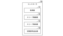
- FIG. 2 is a diagram showing an example of the configuration of a controller 50 in an embodiment.
- the controller 50 includes an acquisition unit 51, a sleep control unit 52, a sleep detection unit 53, and a switching signal transmission unit 54.
- the acquisition unit 51 acquires the judgment information from each of the multiple aggregation stations 40.
- the acquisition unit 51 acquires the judgment information from each of the multiple aggregation stations 40, for example, at a predetermined timing or periodically.
- the acquisition unit 51 outputs the acquired judgment information of each aggregation station 40 to the sleep control unit 52.
- the sleep control unit 52 judges whether or not the aggregation station 40 can sleep based on the judgment information of each aggregation station 40 acquired by the acquisition unit 51.
- the sleep control unit 52 judges, for example, whether or not the aggregation station to be put to sleep can sleep.
- the sleep control unit 52 judges that the sleep-target aggregate station can sleep if the period during which the traffic volume of the sleep-target aggregate station remains below the threshold continues for a predetermined period of time or longer and if other aggregate stations 40 can accommodate the fronthaul multiplexing device 20.
- the sleep control unit 52 determines that the sleep target aggregate station cannot sleep if the traffic volume of the sleep target aggregate station is equal to or greater than the threshold, or if the traffic volume of the sleep target aggregate station is less than the threshold but other aggregate stations 40 cannot accommodate the fronthaul multiplexing device 20.
- the sleep control unit 52 judges that the sleep target aggregate station can sleep if the number of connected terminals of the sleep target aggregate station (e.g., the number of antenna stations 10) falls below a predetermined standard and other aggregate stations 40 can accommodate the connected terminals of the sleep target aggregate station.
- the sleep control unit 52 determines that the sleep target aggregate station cannot sleep if the number of connected terminals of the sleep target aggregate station is equal to or greater than a predetermined criterion. Alternatively, the sleep control unit 52 may determine that the sleep target aggregate station cannot sleep if other aggregate stations 40 cannot accommodate the connected terminals of the sleep target aggregate station even if the number of connected terminals of the sleep target aggregate station falls below a predetermined criterion.
- the sleep control unit 52 determines that sleep is possible, it notifies the sleep detection unit 53 that the sleep target aggregation station will be put to sleep. Furthermore, if the sleep control unit 52 determines that sleep is possible, it sends a sleep instruction to the sleep target aggregation station.
- the sleep instruction is an instruction to execute a transition to a sleep state.
- the sleep detection unit 53 detects the transition of the sleep target aggregation station to a sleep state in response to a notification from the sleep control unit 52.
- the switching signal sending unit 54 sends to the optical distribution unit 30 a switching signal including an instruction to switch the accommodation of the fronthaul multiplexing device 20.
- the switching signal includes, for example, identification information of the aggregate station 40 to be switched to and information indicating the timing of switching. Furthermore, the switching signal sending unit 54 sends to the fronthaul multiplexing device 20 a control signal including information on the delay time.
- the switching signal sending unit 54 sends to the fronthaul multiplexing device 20 a control signal including information indicating the timing of switching of the optical distribution unit 30.
- the switching signal transmitter 54 acquires information on the delay time to be applied when the connection is switched to another aggregate station 40 (e.g., aggregate station 40-2) so that the delay between the aggregate station 40 (e.g., aggregate station 40-1) to which the fronthaul multiplexing device 20 is currently connected does not change.
- the switching signal transmitter 54 acquires, for example, the difference between a first delay time required for transfer between the fronthaul multiplexing device 20 and aggregate station 40-1 and a second delay time required for transfer between the fronthaul multiplexing device 20 and aggregate station 40-2 as the delay time to be applied. Note that if three or more aggregate stations 40 are provided, the switching signal transmitter 54 performs the same process.
- FIG. 3 is a diagram showing an example of the configuration of a fronthaul multiplexing device 20 in an embodiment.
- the fronthaul multiplexing device 20 includes a lower-order delay insertion unit 21, a signal merging unit 22, a switching signal processing unit 23, and an upper-order delay insertion unit 24.
- the lower-side delay insertion unit 21 receives each upstream signal output from each of the multiple antenna stations 10. Using each received upstream signal, the lower-side delay insertion unit 21 imparts a delay to some of the upstream signals so that they appear to have been received at the same time. The lower-side delay insertion unit 21 imparts a delay to the upstream signals according to the difference in distance, for example.
- the signal combining unit 22 multiplexes each upstream signal, including the upstream signal to which a delay has been applied by the lower-side delay insertion unit 21, to generate a multiplexed signal.
- the switching signal processing unit 23 receives a control signal transmitted from the controller 50.
- the switching signal processing unit 23 acquires delay time information contained in the received control signal and information indicating the switching timing of the optical distribution unit 30.
- the switching signal processing unit 23 switches the delay value imparted by the upper-side delay insertion unit 24 based on the switching timing of the optical distribution unit 30. For example, the switching signal processing unit 23 switches the delay value so that the upper-side delay insertion unit 24 imparts the delay value indicated by the delay time information to the switching timing of the optical distribution unit 30.
- the upper delay insertion unit 24 imparts the delay value switched by the switching signal processing unit 23 to the multiplexed signal output from the signal merging unit 22. Note that the upper delay insertion unit 24 does not need to impart a delay to the t term if the delay value has not been switched by the switching signal processing unit 23.
- FIG. 4 is a diagram for explaining a method for calculating the delay time to be applied in the embodiment.
- the switching signal sending unit 54 obtains the propagation delay time difference (upper side delay difference A in FIG. 4) by calculating the difference between the first delay time required for transfer between the fronthaul multiplexing device 20 and the aggregation station 40-1 and the second delay time required for transfer between the fronthaul multiplexing device 20 and the aggregation station 40-2.
- the fronthaul multiplexing device 20 adds a propagation delay time difference to the multiplexed signal and transmits the multiplexed signal to the post-switching aggregation station 40-2. Even if switching is made to aggregation station 40-2, which performs baseband signal processing at the same timing as aggregation station 40-1 due to time synchronization, the signal is transmitted just in time for the upstream baseband processing after switching, eliminating the need for another propagation delay that would accompany a link disconnection.
- loss associated with switching can be avoided (when A>B) by matching the additional insertion delay difference with the switching timing of the optical distribution unit 30. Note that loss can be reduced when A ⁇ B.
- the delay to the aggregation station 40 may be set to 0, but if it is set to be equal to or greater than the propagation time of the switching command from the controller 50, the delay difference and switching time B can be made to overlap.
- the switching signal transmission unit 54 of the controller 50 measures the delay time between the fronthaul multiplexing device 20 and each aggregate station 40 (step S101). For example, the switching signal transmission unit 54 measures a first delay time between the fronthaul multiplexing device 20 and aggregate station 40-1, and a second delay time between the fronthaul multiplexing device 20 and aggregate station 40-2.
- the switching signal transmitter 54 uses the measured delay time between the fronthaul multiplexer 20 and each aggregate station 40 to obtain a delay time to be applied when the connection is switched to another aggregate station 40 so that the delay between the aggregate station 40 to which the fronthaul multiplexer 20 is connected does not change (step S102). Specifically, the switching signal transmitter 54 obtains the delay time to be applied, which is the difference between the delay time of the aggregate station 40 to which the fronthaul multiplexer 20 is connected (e.g., a first delay time) and the delay time of the other aggregate station 40 (e.g., a second delay time).
- the switching signal transmitter 54 notifies the fronthaul multiplexer 20 of a control signal including the acquired information on the delay time to be imparted (step S103).
- the switching signal processor 23 of the fronthaul multiplexer 20 acquires the control signal sent from the controller 50.
- the switching signal processor 23 acquires the information on the delay time to be imparted contained in the acquired control signal (step S104).
- the switching signal processor 23 stores the acquired information on the delay time to be imparted in association with the identification information of the central station 40 (step S105).
- FIG. 7 is a sequence diagram showing the flow of the switching process performed by the communication system 100 in the embodiment.
- the aggregation stations 40-1 and 40-2 are described as an aggregation station group when no particular distinction is made.
- the fronthaul multiplexing device 20 is connected to the aggregation station 40-1 via the optical distribution unit 30.
- the acquisition unit 51 of the controller 50 acquires information on the traffic volume of each aggregate station 40 (step S201).
- the acquisition unit 51 outputs the acquired information on the traffic volume of each aggregate station 40 to the sleep control unit 52.
- the sleep control unit 52 judges whether or not to put the aggregate station 40 to sleep based on the traffic volume information of each aggregate station 40 output from the acquisition unit 51 (step S202). For example, it is assumed that the sleep control unit 52 judges that the aggregate station 40-1 can be put to sleep. In this case, the sleep control unit 52 transmits a sleep instruction to the aggregate station 40-1 (step S203). This allows the aggregate station 40-1 to transition to a sleep state.
- the sleep control unit 52 may transmit a sleep instruction to the aggregation station 40-1 after the optical distribution unit 30 makes the switch.
- the sleep control unit 52 notifies the sleep detection unit 53 that the aggregation station 40-1 will be put to sleep.
- the sleep detection unit 53 detects the sleep of the aggregation station 40-1 to which the fronthaul multiplexing device 20 is currently connected based on the notification from the sleep control unit 52.
- the sleep detection unit 53 determines the aggregation station 40 that will accommodate the fronthaul multiplexing device 20 that was connected to the aggregation station 40-1 (step S204).
- the sleep detection unit 53 has determined that the aggregation station 40-2 will accommodate the fronthaul multiplexing device 20 that was connected to the aggregation station 40-1.
- the method of determining the accommodation of the fronthaul multiplexing device 20 is not particularly limited.
- an aggregation station 40 that already accommodates devices other than the fronthaul multiplexing device 20 (e.g., an antenna station 10 that is not connected to the fronthaul multiplexing device 20) and can process the fronthaul multiplexing device 20 may be determined as the accommodation of the fronthaul multiplexing device 20. This makes it possible to aggregate multiple devices in a single aggregation station 40.
- the sleep detection unit 53 notifies the switching signal sending unit 54 of the determined accommodation destination.
- the switching signal sending unit 54 sends a control signal including information indicating the switching timing of the optical distribution unit 30 to the fronthaul multiplexing device 20 (step S205). Furthermore, the switching signal sending unit 54 sends a switching signal to the optical distribution unit 30 (step S206).
- the optical distribution unit 30 receives the switching signal sent from the controller 50.
- the optical distribution unit 30 performs switching at the timing included in the switching signal (step S207). For example, the optical distribution unit 30 performs switching at the timing included in the switching signal to connect the first port to which the fronthaul multiplexing device 20 is connected and the second port to which the aggregation station 40-2 is connected.
- the switching signal processing unit 23 of the fronthaul multiplexing device 20 receives the control signal sent from the controller 50.
- the switching signal processing unit 23 sets the delay value indicated by the delay time information in the upper-level delay insertion unit 24 (step S208).
- the delay value is switched so that the upper-level delay insertion unit 24 imparts the delay value indicated by the delay time information.
- the lower-side delay insertion unit 21 of the fronthaul multiplexing device 20 receives each upstream signal output from each of the multiple antenna stations 10 (step S209).
- the lower-side delay insertion unit 21 inserts a delay into a portion of each received upstream signal (step S210). Note that the insertion of delay is the same as in the past.
- the lower-side delay insertion unit 21 outputs each upstream signal, including the delayed upstream signal, to the signal combining unit 22.
- the signal combining unit 22 multiplexes each upstream signal, including the upstream signal to which a delay has been applied by the lower-side delay insertion unit 21, to generate a multiplexed signal (step S211).
- the signal combining unit 22 outputs the generated multiplexed signal to the upper-side delay insertion unit 24.
- the upper-side delay insertion unit 24 applies a delay value set by the switching signal processing unit 23 to the multiplexed signal output from the signal combining unit 22 (step S212).
- the upper-side delay insertion unit 24 then outputs the multiplexed signal to the optical distribution unit 30 after a delay time corresponding to the delay value has elapsed (step S213).
- the multiplexed signal input to the optical distribution unit 30 is transferred to the aggregation station 40-2, which is the new accommodation destination.
- the controller 50 sends a switching signal to the optical distribution unit 30, and includes a switching signal sending unit 54 that sends a control signal to the fronthaul multiplexing device 20 including information on the delay time to be added to the multiplexed signal by the fronthaul multiplexing device 20 so that the delay time does not change before and after switching the central station 40.
- the fronthaul multiplexing device 20 obtains information on the delay time to be added to the multiplexed signal included in the control signal from the controller 50 in advance, and includes a switching signal processing unit 23 that switches the delay value to be added to the multiplexed signal at the timing of switching the optical distribution unit 30, and an upper delay insertion unit 24 that adds the delay value switched by the switching signal processing unit 23 to the multiplexed signal.
- power saving measures can be applied in cases where power saving measures such as putting the aggregation station 40 to sleep cannot be applied because the allowable interruption time is limited.
- the controller 50 may be configured to wake up the sleeping aggregate station 40.
- the sleep control unit 52 judges whether or not the sleep of the aggregate station 40-1 needs to be woken up, for example, based on judgment information acquired from the aggregate station 40-2 that is not in a sleep state.
- the sleep control unit 52 judges that the sleep of the aggregate station 40-1 needs to be woken up when the traffic volume of the aggregate station 40-2 that is not in a sleep state becomes equal to or exceeds a predetermined threshold (for example, 50 percent of the traffic volume that can be processed by the aggregate station 40-2).
- the sleep control unit 52 determines that it is not necessary to wake up the aggregation station 40-1 from sleep. Note that, although the example described here uses the traffic volume as the judgment information, when other information is used as the judgment information, the judgment is based on other judgment criteria.
- the sleep control unit 52 determines that a sleep wakeup is necessary, it notifies the sleep detection unit 53 to wake up the sleeping aggregation station 40-1. Furthermore, if the sleep control unit 52 determines that a sleep wakeup is necessary, it transmits a sleep wakeup instruction to the sleeping aggregation station 40-1.
- the sleep wakeup instruction is an instruction for executing a return from the sleep state.
- the aggregation station 40-1 returns from the sleep state in response to receiving the sleep wakeup instruction transmitted from the controller 50.
- the sleep detection unit 53 detects the wake-up of the sleeping aggregation station 40-1 in response to a notification from the sleep control unit 52 indicating that the sleeping aggregation station 40-1 is to be woken up.
- the switching signal sending unit 54 sends a switching signal to the optical distribution unit 30 including an instruction to switch the accommodation of the fronthaul multiplexing device 20.
- the switching signal sending unit 54 sends a switching signal to the optical distribution unit 30 including an instruction to switch the accommodation of the fronthaul multiplexing device 20 to the aggregation station 40-1 that is returning from the sleep state.
- the switching signal transmission unit 54 sends a control signal including information indicating the switching timing of the optical distribution unit 30 to the fronthaul multiplexing device 20.
- the switching signal processing unit 23 of the fronthaul multiplexing device 20 receives the control signal sent from the controller 50. Based on the received control signal, the switching signal processing unit 23 sets the delay value to be set in the upper-side delay insertion unit 24 to the delay value before switching. For example, the switching signal processing unit 23 switches the delay value so that the upper-side delay insertion unit 24 imparts the delay value indicated by the delay time information to the switching timing of the optical distribution unit 30. This makes it possible to switch back to the state before switching.
- the communication system 100 may be configured to include a wireless controller that wirelessly communicates with the aggregate station 40.
- the wireless controller includes the acquisition unit 51 and sleep control unit 52 that the controller 50 includes, and the controller 50 does not include the acquisition unit 51 or the sleep control unit 52.
- the sleep control unit 52 of the wireless controller determines that sleep is possible, it notifies the controller 50 that the sleep target aggregate station will be put to sleep.
- the sleep detection unit 53 of the controller 50 detects the transition of the sleep target aggregate station to a sleep state. Thereafter, the same processing as in the above-mentioned embodiment is performed.
- At least some or all of the functional units of the fronthaul multiplexer 20 and the controller 50 are realized as software by a processor such as a CPU (Central Processing Unit) executing a program stored in a storage device having a non-volatile recording medium (non-transient recording medium) and in the storage unit.
- the program may be recorded on a computer-readable non-transient recording medium.
- Examples of computer-readable non-transient recording media include portable media such as flexible disks, optical magnetic disks, ROMs (Read Only Memory), and CD-ROMs (Compact Disc Read Only Memory), and storage devices such as hard disks built into computer systems.
- At least some or all of the functional units of the fronthaul multiplexer 20, or some or all of the functional units of the controller 50 may be realized using hardware including electronic circuits (electronic circuits or circuitry) using, for example, an LSI (Large Scale Integrated circuit), an ASIC (Application Specific Integrated Circuit), a PLD (Programmable Logic Device), or an FPGA (Field Programmable Gate Array).
- electronic circuits electronic circuits or circuitry
- LSI Large Scale Integrated circuit
- ASIC Application Specific Integrated Circuit
- PLD Programmable Logic Device
- FPGA Field Programmable Gate Array
- the present invention can be applied to a communication system equipped with a fronthaul multiplexing device.
Landscapes
- Engineering & Computer Science (AREA)
- Computer Networks & Wireless Communication (AREA)
- Signal Processing (AREA)
- Mobile Radio Communication Systems (AREA)
Abstract
Description
本発明は、制御装置、フロントホール多重装置、接続切替方法及び多重方法に関する。 The present invention relates to a control device, a fronthaul multiplexing device, a connection switching method, and a multiplexing method.
図8は、従来の通信システムSの一例を示す図である。通信システムSは、複数のアンテナ局1-1,1-2と、フロントホール多重装置2と、集約局3とを備える。アンテナ局1-1,1-2は、移動通信システムにおけるRU(Radio Unit)である。集約局3は、移動通信システムにおけるCU/DU(Central Unit/ Distributed Unit)である。図8に示すように、無線区間の周波数リソースとベースバンド処理を行う集約局3を有効活用するために、異なる地点に設置されたアンテナ局1-1,1-2との間に、フロントホール多重装置(FHM:FrontHaul. Multiplexer)2と呼ばれる装置が配置される。
Figure 8 is a diagram showing an example of a conventional communication system S. The communication system S comprises multiple antenna stations 1-1, 1-2, a
フロントホール多重装置2は、集約局3から見て、フロントホール多重装置2に接続された複数台のアンテナ局1-1,1-2を1台のアンテナ局に見えるように振る舞う。具体的には、フロントホール多重装置2は、複数のアンテナ局1-1,1-2から受信した上り信号に対して、同一時刻に相当する信号に対する信号処理を行い、信号を併合する。フロントホール多重装置2と各アンテナ局1-1,1-2との間の距離に応じて、フロントホール多重装置2で各上り信号を受信する時刻が異なる。そのため、フロントホール多重装置2は、受信した上り信号に対して距離差に応じた遅延を付与した後に信号の併合を行った上で信号処理を行う。ここで遅延を付与とは、信号に対して遅延を挿入して遅延させることを意味する。
The
図9は、フロントホール多重装置2が行う処理の概要を説明するための図である。図9に示すように、フロントホール多重装置2と各アンテナ局1-1,1-2との間の距離に応じて、アンテナ局1-1から送信された上り信号がアンテナ局1-2から送信された上り信号よりも先にフロントホール多重装置2に届いたとする。この場合、フロントホール多重装置2は、アンテナ局1-1から送信された上り信号に対して遅延を付与することで、各アンテナ局1-1,1-2から送信された上り信号の受信時刻を合わせる。その後、フロントホール多重装置2は、各アンテナ局1-1,1-2から送信された上り信号を多重することによって多重信号を生成する。
FIG. 9 is a diagram for explaining an overview of the processing performed by the
このようにフロントホール多重装置2を用いることによって、必要な集約局3のポート数及び、フロントホール多重装置2から集約局3の間に必要なファイバ本数を削減することができる。フロントホール多重装置2は上り方向では、アンテナで受信した信号(受信電力を量子化したもの)を加算(もしくは選択)して、1つのアンテナからの受信信号に見せかける。そのため、加算時にサンプリング時刻がずれないようにする調整する必要がある。なお、5G向けのフロントホール多重装置2も開発されている。
By using the
図10は、従来の通信システムSaの一例を示す図である。通信システムSaは、複数のアンテナ局1-1,1-2と、フロントホール多重装置2と、複数の集約局3-1,3-2と、光振分部4と、コントローラ5を備える。図10では、集約局3-1の利用状況に応じてフロントホール多重装置2の接続を集約局3-2に変更する場合(例えば集約局3-1におけるトラフィック量が著しく少ない場合に、アンテナ局1-1,1-2の収容を集約局3-2に統合する場合)の処理について説明する。この場合、監視制御用のコントローラ5が、集約局3-1におけるトラフィック量が一定量以下に低下したことを契機に、光振分部4の接続を切り替えて、フロントホール多重装置2から集約局3-2に接続先を変更することもできる。
FIG. 10 is a diagram showing an example of a conventional communication system Sa. The communication system Sa includes multiple antenna stations 1-1 and 1-2, a
しかしながら、光振分部4を切り替えて、アンテナ局1-1,1-2を収容するフロントホール多重装置2を、集約局3-1から集約局3-2に変更しようとした場合には、フロントホール多重装置2から集約局3-1の距離と、フロントホール多重装置2から集約局3-2への距離が異なり、遅延差が生じてしまう。これにより、集約局3とアンテナ局1との間でリンク切断が発生し、再度集約局3とアンテナ局1との間で遅延測定を含むリンク確立のための手順が行われることになる。その結果、その間の期間は通信断となってしまうという問題があった。
However, when attempting to change the
上記事情に鑑み、本発明は、フロントホール多重装置の接続先が異なる装置に変更になった場合であっても、通信断の時間を短縮することができる技術の提供を目的としている。 In light of the above circumstances, the present invention aims to provide technology that can shorten the time that communication is interrupted, even when the connection destination of the fronthaul multiplexing device is changed to a different device.
本発明の一態様は、端末と通信を行う複数の端末収容局から出力された各信号のタイミングを調整することで各信号を多重した多重信号を光振分部を介して振り分け先に出力するフロントホール多重装置の収容先を第1の通信局から第2の通信局に切り替えさせる指示を含む切替信号を前記光振分部に対して送出し、通信局の切替前後で遅延時間が変化しないように前記フロントホール多重装置で前記多重信号に付与する遅延時間の情報を含む制御信号を前記フロントホール多重装置に送出する切替信号送出部、を備える制御装置である。 One aspect of the present invention is a control device that includes a switching signal sending unit that sends a switching signal to an optical distribution unit including an instruction to switch the accommodation of a fronthaul multiplexing device that outputs a multiplexed signal, which is obtained by multiplexing each signal by adjusting the timing of each signal output from a plurality of terminal accommodation stations that communicate with a terminal, to an allocation destination via an optical distribution unit, from a first communication station to a second communication station, and sends to the fronthaul multiplexing device a control signal including information on the delay time to be imparted to the multiplexed signal by the fronthaul multiplexing device so that the delay time does not change before and after the communication station switching.
本発明の一態様は、端末と通信を行う複数の端末収容局と、前記複数の端末収容局から出力された各信号のタイミングを調整することで各信号を多重した多重信号を出力するフロントホール多重装置と、前記フロントホール多重装置から出力された前記多重信号を振り分け先に出力する光振分部とを備える通信システムにおける前記フロントホール多重装置であって、前記複数の端末収容局それぞれから出力された各信号の送出タイミングを調整する下位側遅延挿入部と、前記下位側遅延挿入部によって調整された各信号を多重して前記多重信号を生成する信号併合部と、前記光振分部の切り替えに関する情報と、前記多重信号に付与する遅延時間の情報とを含む制御信号を外部から受信し、前記制御信号の受信に応じて前記制御信号に含まれる前記多重信号に付与する遅延時間の情報で示される遅延値を前記多重信号に付与すべき遅延値に切り替える切替信号処理部と、前記切替信号処理部によって切り替えられた遅延値を前記多重信号に対して付与する上位側遅延挿入部と、を備えるフロントホール多重装置である。 One aspect of the present invention is a fronthaul multiplexing device in a communication system including a plurality of terminal accommodating stations that communicate with terminals, a fronthaul multiplexing device that adjusts the timing of each signal output from the plurality of terminal accommodating stations to output a multiplexed signal obtained by multiplexing each signal, and an optical distribution unit that outputs the multiplexed signal output from the fronthaul multiplexing device to an allocation destination, the fronthaul multiplexing device including a lower side delay insertion unit that adjusts the timing of each signal output from each of the plurality of terminal accommodating stations, a signal merging unit that multiplexes each signal adjusted by the lower side delay insertion unit to generate the multiplexed signal, a switching signal processing unit that receives a control signal from the outside, the control signal including information regarding switching of the optical distribution unit and information regarding a delay time to be imparted to the multiplexed signal, and in response to receiving the control signal, switches the delay value indicated by the information regarding the delay time to be imparted to the multiplexed signal, included in the control signal, to a delay value to be imparted to the multiplexed signal, and an upper side delay insertion unit that imparts the delay value switched by the switching signal processing unit to the multiplexed signal.
本発明の一態様は、端末と通信を行う複数の端末収容局から出力された各信号のタイミングを調整することで各信号を多重した多重信号を光振分部を介して振り分け先に出力するフロントホール多重装置の収容先を第1の通信局から第2の通信局に切り替えさせる指示を含む切替信号を前記光振分部に対して送出し、通信局の切替前後で遅延時間が変化しないように前記フロントホール多重装置で前記多重信号に付与する遅延時間の情報を含む制御信号を前記フロントホール多重装置に送出する、接続切替方法である。 One aspect of the present invention is a connection switching method that includes sending a switching signal to an optical distribution unit that includes an instruction to switch the accommodation of a fronthaul multiplexing device that outputs a multiplexed signal, which is obtained by multiplexing signals by adjusting the timing of each signal output from multiple terminal accommodation stations that communicate with a terminal, to the optical distribution unit from a first communication station to a second communication station, and sending to the fronthaul multiplexing device a control signal that includes information on the delay time to be imparted to the multiplexed signal by the fronthaul multiplexing device so that the delay time does not change before and after the communication station switch.
本発明の一態様は、端末と通信を行う複数の端末収容局と、前記複数の端末収容局から出力された各信号のタイミングを調整することで各信号を多重した多重信号を出力するフロントホール多重装置と、前記フロントホール多重装置から出力された前記多重信号を振り分け先に出力する光振分部とを備える通信システムにおける前記フロントホール多重装置が行う多重方法であって、前記複数の端末収容局それぞれから出力された各信号の送出タイミングを調整し、調整された各信号を多重して前記多重信号を生成し、前記光振分部の切り替えに関する情報と、前記多重信号に付与する遅延時間の情報とを含む制御信号を外部から受信し、前記制御信号の受信に応じて、前記制御信号に含まれる前記多重信号に付与する遅延時間の情報で示される遅延値を前記多重信号に付与すべき遅延値に切り替え、切り替えられた遅延値を前記多重信号に対して付与する、多重方法である。 One aspect of the present invention is a multiplexing method performed by a fronthaul multiplexing device in a communication system including a plurality of terminal accommodating stations that communicate with terminals, a fronthaul multiplexing device that outputs a multiplexed signal by multiplexing each signal by adjusting the timing of each signal output from the plurality of terminal accommodating stations, and an optical distribution unit that outputs the multiplexed signal output from the fronthaul multiplexing device to an allocation destination, the multiplexing method comprising: adjusting the transmission timing of each signal output from each of the plurality of terminal accommodating stations, multiplexing the adjusted signals to generate the multiplexed signal, receiving from an external device a control signal including information regarding switching of the optical distribution unit and information regarding a delay time to be imparted to the multiplexed signal, switching the delay value indicated by the information regarding the delay time to be imparted to the multiplexed signal included in the control signal to a delay value to be imparted to the multiplexed signal in response to receiving the control signal, and imparting the switched delay value to the multiplexed signal.
本発明により、フロントホール多重装置の接続先が異なる装置に変更になった場合であっても、通信断の時間を短縮することが可能となる。 The present invention makes it possible to reduce the time that communication is interrupted, even if the connection destination of the fronthaul multiplexing device is changed to a different device.
以下、本発明の一実施形態を、図面を参照しながら説明する。
図1は、実施形態における通信システム100の構成例を示す図である。通信システム100は、1以上のアンテナ局10と、フロントホール多重装置20と、光振分部30と、1以上の集約局40と、コントローラ50とを備える。図1では、通信システム100が、3台のアンテナ局10-1~10-3を備え、2台の集約局40-1~40-2を備える場合を示しているが、アンテナ局10及び集約局40の台数は特に限定されない。
Hereinafter, an embodiment of the present invention will be described with reference to the drawings.
Fig. 1 is a diagram showing an example of the configuration of a
以下の説明において、アンテナ局10-1~10-3について特に区別しない場合にはアンテナ局10と記載し、集約局40-1~40-2について特に区別しない場合には集約局40と記載する。以下では、アンテナ局10から集約局40に向かう方向を上り方向として説明する。 In the following description, antenna stations 10-1 to 10-3 will be referred to as antenna station 10 unless otherwise specified, and aggregation stations 40-1 to 40-2 will be referred to as aggregation station 40 unless otherwise specified. In the following description, the direction from antenna station 10 to aggregation station 40 will be referred to as the uplink direction.
アンテナ局10-1,10-2とフロントホール多重装置20との間、フロントホール多重装置20と光振分部30との間、光振分部30と集約局40-1,40-2との間、アンテナ局10-3と集約局40-2との間は光伝送路で接続される。光伝送路は、例えば光ファイバであり、光信号を伝送する。コントローラ50とフロントホール多重装置20との間、コントローラ50と光振分部30との間、コントローラ50と集約局40-1,40-2との間は電気信号を伝送する電気線で接続される。
Optical transmission paths connect the antenna stations 10-1, 10-2 and the
図1において、アンテナ局10-1,10-2はフロントホール多重装置20に収容され、アンテナ局10-3は集約局40-2に収容される。フロントホール多重装置20は、光振分部30を介して集約局40-1又は集約局40-2のいずれかに収容される。光振分部30、集約局40-1及びコントローラ50は拠点1内に設置され、集約局40-2は拠点2内に設置される。拠点1と拠点2は、地理的に離れた場所に設置される。
In FIG. 1, antenna stations 10-1 and 10-2 are accommodated in a
アンテナ局10は、通信可能範囲を表すセルS1,S2,S3内に位置する端末との間で通信を行う。アンテナ局10-1は、例えばセルS1内に位置する端末との間で通信を行う。
同様に、アンテナ局10-2,10-3は、例えばセルS2,S3内に位置する端末との間で通信を行う。アンテナ局10は、端末から送信された上り信号を受信する。アンテナ局10は、移動通信システムにおけるRUである。アンテナ局10は、端末収容局の一態様である。
The antenna station 10 communicates with terminals located within cells S1, S2, and S3 that represent communication coverage areas. The antenna station 10-1 communicates with a terminal located within cell S1, for example.
Similarly, the antenna stations 10-2 and 10-3 communicate with terminals located in, for example, cells S2 and S3. The antenna station 10 receives an uplink signal transmitted from the terminal. The antenna station 10 is an RU in the mobile communication system. The antenna station 10 is one aspect of a terminal accommodating station.
フロントホール多重装置20は、集約局40から見て、接続している複数台のアンテナ局10を1台のアンテナ局10に見えるように振る舞う。フロントホール多重装置20は、各アンテナ局10から送信された上り信号を受信する。フロントホール多重装置20は、受信した各上り信号に対して、同一時刻に相当する信号に対する信号処理を行うことによって各上り信号を併合する。これにより、フロントホール多重装置20は、多重信号を生成する。
The
さらにフロントホール多重装置20は、接続先となる集約局40が切り替わる場合、接続中の集約局40との遅延が変化しないように、接続先となる集約局40へ接続が切り替わった際に多重信号に付与する遅延時間の情報をコントローラ50から取得する。フロントホール多重装置20は、接続先となる集約局40が切り替わるタイミングで、取得した遅延時間の情報で示される遅延値を多重信号に付与する。これにより、フロントホール多重装置20は、多重信号の送信タイミングを調整する。
Furthermore, when the destination aggregate station 40 is switched, the
光振分部30は、1以上の第1ポートと、複数の第2ポートとを有し、あるポートから入力された光信号を他のポートから出力する光振分装置である。光振分部30の第1ポートにはフロントホール多重装置20が接続され、光振分部30の第2ポートには集約局40-1,40-2が接続される。光振分部30は、コントローラ50の制御に従って、フロントホール多重装置20が接続されている第1ポートと、フロントホール多重装置20の収容先となる集約局40が接続されている第2ポートとを接続する。これにより、光振分部30は、フロントホール多重装置20から送信された多重信号を集約局40-1又は40-2に転送する。光振分部30は、光スイッチであってもよいし、マルチキャストスイッチであってもよいし、他のスイッチであってもよい。
The
集約局40は、光振分部30から転送された多重信号を処理、又は、上位に転送する。さらに集約局40は、コントローラ50からの指示に応じて、スリープ状態に移行する。スリープ状態とは、一部の機能を停止させることで省電力化を図る機能である。集約局40は、移動通信システムにおけるDUである。集約局40-1は、第1の通信局の一態様であり、集約局40-2は、第2の通信局の一態様である。集約局40は、通信局の一態様である。
The aggregation station 40 processes the multiplexed signal transferred from the
コントローラ50は、通信システム100全体を制御する。コントローラ50は、集約局40のスリープ制御に用いる判断情報を複数の集約局40それぞれから取得する。判断情報は、例えばトラフィック量、接続端末数、トラフィックの流通量、割当量、CQI(Channel Quality Indicator)等の無線品質情報、疎通する5QIなどの優先度情報や契約サービスの情報等である。以下では、判断材料がトラフィック量であるものとして説明する。
The
コントローラ50は、判断情報に基づいて、フロントホール多重装置20を収容している集約局40(以下「スリープ対象集約局」という。)をスリープ状態に移行できると判断した場合、光振分部30に対して切り替えを指示する。さらにコントローラ50は、フロントホール多重装置20に対して遅延時間の情報を通知する。コントローラ50は、光振分部30の切り替え前又は切り替え後において、スリープ対象の集約局40に対してスリープを指示する。
If the
図2は、実施形態におけるコントローラ50の構成例を示す図である。コントローラ50は、取得部51と、スリープ制御部52と、スリープ検知部53と、切替信号送出部54を備える。
FIG. 2 is a diagram showing an example of the configuration of a
取得部51は、判断情報を複数の集約局40それぞれから取得する。取得部51は、例えば予め定められたタイミング、又は、周期的に判断情報を複数の集約局40それぞれから取得する。取得部51は、取得した各集約局40の判断情報をスリープ制御部52に出力する。
The
スリープ制御部52は、取得部51によって取得された各集約局40の判断情報に基づいて集約局40のスリープ可否を判断する。スリープ制御部52は、例えばスリープ対象集約局のスリープ可否を判断する。
The
(判断情報がトラフィック量の場合のスリープ可否判断)
判断情報がトラフィック量である場合、スリープ制御部52は、スリープ対象集約局のトラフィック量が閾値未満になった期間が所定の期間以上継続した場合であって、他の集約局40がフロントホール多重装置20を収容できる場合に、スリープ対象集約局をスリープ可能と判断する。
(Sleep decision when decision information is traffic volume)
When the judgment information is traffic volume, the
一方、スリープ制御部52は、スリープ対象集約局のトラフィック量が閾値以上の場合、又は、スリープ対象集約局のトラフィック量が閾値未満であっても他の集約局40がフロントホール多重装置20を収容できない場合に、スリープ対象集約局をスリープ不可能と判断する。
On the other hand, the
(判断情報が接続端末数の場合のスリープ可否判断)
判断情報が接続端末数である場合、スリープ制御部52は、スリープ対象集約局の接続端末数(例えば、アンテナ局10の数)が予め定められた基準を下回った場合であって、他の集約局40がスリープ対象集約局の接続端末を収容できる場合に、スリープ対象集約局をスリープ可能と判断する。
(Sleep permission judgement when judgement information is number of connected terminals)
When the judgment information is the number of connected terminals, the
一方、スリープ制御部52は、スリープ対象集約局の接続端末数が予め定められた基準以上の場合に、スリープ対象集約局をスリープ不可能と判断する。又は、スリープ制御部52は、スリープ対象集約局の接続端末数が予め定められた基準を下回った場合であっても他の集約局40がスリープ対象集約局の接続端末を収容できない場合に、スリープ対象集約局をスリープ不可能と判断してもよい。
On the other hand, the
スリープ制御部52は、スリープ可能と判断した場合、スリープ対象集約局をスリープさせることをスリープ検知部53に通知する。さらに、スリープ制御部52は、スリープ可能と判断した場合、スリープ対象集約局に対してスリープ指示を送信する。スリープ指示は、スリープ状態への移行を実行させるための指示である。
If the
スリープ検知部53は、スリープ制御部52からの通知に応じて、スリープ対象集約局のスリープ状態への移行を検知する。
The
切替信号送出部54は、スリープ検知部53によりスリープ対象集約局のスリープ状態への移行が検知された場合、フロントホール多重装置20の収容先を切り替えさせる指示を含む切替信号を光振分部30に対して送出する。切替信号には、例えば切替先となる集約局40の識別情報と、切り替えるタイミングを示す情報とが含まれる。さらに、切替信号送出部54は、遅延時間の情報を含む制御信号をフロントホール多重装置20に送出する。切替信号送出部54は、スリープ検知部53によりスリープ対象集約局のスリープ状態への移行が検知された場合、光振分部30の切り替えタイミングを示す情報を含む制御信号をフロントホール多重装置20に送出する。
When the
切替信号送出部54は、フロントホール多重装置20が接続中の集約局40(例えば、集約局40-1)との遅延が変化しないように、他の集約局40(例えば、集約局40-2)へ接続が切り替わった際に付与する遅延時間の情報を取得している。切替信号送出部54は、例えばフロントホール多重装置20と集約局40-1との間の転送に要する第1遅延時間と、フロントホール多重装置20と集約局40-2との間の転送に要する第2遅延時間との差を、付与する遅延時間として取得しておく。なお、集約局40が3台以上備えられている場合には、切替信号送出部54は同様の処理を行う。
The
図3は、実施形態におけるフロントホール多重装置20の構成例を示す図である。フロントホール多重装置20は、下位側遅延挿入部21と、信号併合部22と、切替信号処理部23と、上位側遅延挿入部24とを備える。
FIG. 3 is a diagram showing an example of the configuration of a
下位側遅延挿入部21は、複数のアンテナ局10それぞれから出力された各上り信号を受信する。下位側遅延挿入部21は、受信した各上り信号を用いて、同一時刻に受信されたようにするために一部の上り信号に遅延を付与する。下位側遅延挿入部21は、例えば上り信号に対して距離差に応じた遅延を付与する。
The lower-side
信号併合部22は、下位側遅延挿入部21によって遅延が付与された上り信号を含む各上り信号を多重して多重信号を生成する。
The
切替信号処理部23は、コントローラ50から送信された制御信号を受信する。切替信号処理部23は、受信した制御信号に含まれる遅延時間の情報と、光振分部30の切り替えタイミングを示す情報とを取得する。切替信号処理部23は、光振分部30の切り替えタイミングに基づいて、上位側遅延挿入部24で付与する遅延値の切り替えを行う。例えば、切替信号処理部23は、光振分部30の切り替えタイミングに遅延時間の情報で示される遅延値を上位側遅延挿入部24で付与するように、遅延値の切り替えを行う。光振分部30の切り替えと同時に上位側遅延挿入部24において付与する遅延値を変更することで、集約局40の切り替わりに伴う集約局40とアンテナ局10との間の遅延時間変化によるリンク切断や通信断を防ぐことができる。
The switching
上位側遅延挿入部24は、切替信号処理部23によって切り替えられた遅延値を、信号併合部22から出力された多重信号に対して付与する。なお、上位側遅延挿入部24は、切替信号処理部23によって遅延値の切り替えが行われていない場合にはt項に遅延を付与しなくてよい。
The upper
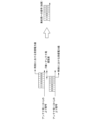
図4は、実施形態における付与する遅延時間の算出方法を説明するための図である。上位側(フロントホール多重装置20と集約局40-1,40-2との間)で図4に示すように伝搬遅延が発生する場合、切替信号送出部54はフロントホール多重装置20と集約局40-1との間の転送に要する第1遅延時間と、フロントホール多重装置20と集約局40-2との間の転送に要する第2遅延時間との差分を算出することによって、伝搬遅延時間差(図4における上位側遅延差A)を取得する。
FIG. 4 is a diagram for explaining a method for calculating the delay time to be applied in the embodiment. When a propagation delay occurs on the upper side (between the
そして、フロントホール多重装置20において、多重信号に伝搬遅延時間差を付与して切り替え後の集約局40-2に多重信号を送信する。時刻同期により、集約局40-1と同じタイミングでベースバンド信号処理が行われる集約局40-2に切り替えられても、切り替え後にちょうど上りベースバンド処理のタイミングに間に合うように送信されるため、リンク断を伴う再度の伝搬遅延が不要となる。
Then, the
さらに、図5に示すように、集約時に遠い距離の(挿入遅延が短い)集約局40から、近い距離の(挿入遅延が長い)集約局40への切替を想定すると、追加となる挿入遅延差と、光振分部30の切り替えタイミングを合わせることで、切り替えに伴うロスも回避(A>Bの場合)させることができる。なお、A≦Bの場合には、ロスを減少させることができる。対集約局40遅延を0としてもよいが、コントローラ50からの切替指示の伝搬時間以上にすると、遅延差と切替時間Bを重複させられる。
Furthermore, as shown in FIG. 5, assuming switching from a distant aggregation station 40 (with a short insertion delay) to a nearby aggregation station 40 (with a long insertion delay) during aggregation, loss associated with switching can be avoided (when A>B) by matching the additional insertion delay difference with the switching timing of the
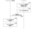
図6は、実施形態における通信システム100が行う事前処理の流れを示すシーケンス図である。ここで事前処理とは、遅延時間の情報を取得する処理である。
コントローラ50の切替信号送出部54は、フロントホール多重装置20と各集約局40との間の遅延時間を測定する(ステップS101)。例えば、切替信号送出部54は、フロントホール多重装置20と集約局40-1との間の第1遅延時間と、フロントホール多重装置20と集約局40-2との間の第2遅延時間を測定する。
6 is a sequence diagram showing the flow of pre-processing performed by the
The switching
切替信号送出部54は、測定したフロントホール多重装置20と各集約局40との間の遅延時間を用いて、フロントホール多重装置20が接続中の集約局40との遅延が変化しないように、他の集約局40へ接続が切り替わった際に付与する遅延時間を取得する(ステップS102)。具体的には、切替信号送出部54は、フロントホール多重装置20が接続中の集約局40の遅延時間(例えば、第1遅延時間)と、他の集約局40の遅延時間(例えば、第2遅延時間)との差分値を付与する遅延時間として取得する。
The
切替信号送出部54は、取得した付与する遅延時間の情報を含む制御信号をフロントホール多重装置20に通知する(ステップS103)。フロントホール多重装置20の切替信号処理部23は、コントローラ50から送信された制御信号を取得する。切替信号処理部23は、取得した制御信号に含まれる付与する遅延時間の情報を取得する(ステップS104)。切替信号処理部23は、取得した付与する遅延時間の情報を集約局40の識別情報に対応付けて保持する(ステップS105)。
The
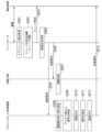
図7は、実施形態における通信システム100が行う切替処理の流れを示すシーケンス図である。図7では、集約局40-1及び40-2について特に区別しない場合には集約局群として記載する。図7の処理開始時には、フロントホール多重装置20が、光振分部30を介して集約局40-1に接続されているものとする。
FIG. 7 is a sequence diagram showing the flow of the switching process performed by the
コントローラ50の取得部51は、各集約局40のトラフィック量の情報を取得する(ステップS201)。取得部51は、取得した各集約局40のトラフィック量の情報をスリープ制御部52に出力する。スリープ制御部52は、取得部51から出力された各集約局40のトラフィック量の情報に基づいてスリープの可否を判断する(ステップS202)。例えば、スリープ制御部52は、集約局40-1をスリープ可能と判断したとする。この場合、スリープ制御部52は、集約局40-1に対してスリープの指示を送信する(ステップS203)。これにより、集約局40-1をスリープ状態に移行させることができる。
The
なお、光振分部30による切り替えが行われる前に集約局40-1をスリープ状態に移行させると、集約局40-1に接続されている装置(例えば、フロントホール多重装置20)から送信された信号が失われてしまう可能性がある。そこで、スリープ制御部52は、光振分部30による切り替えが行われた後に集約局40-1に対してスリープの指示を送信してもよい。
Note that if the aggregation station 40-1 is put into a sleep state before the
さらに、スリープ制御部52は、集約局40-1をスリープさせることをスリープ検知部53に通知する。スリープ検知部53は、スリープ制御部52からの通知により、現在フロントホール多重装置20が接続されている集約局40-1のスリープを検知する。スリープ検知部53は、集約局40-1のスリープの検知に伴い、集約局40-1に接続されていたフロントホール多重装置20の収容先となる集約局40を決定する(ステップS204)。ここで、スリープ検知部53は、集約局40-1に接続されていたフロントホール多重装置20の収容先を、集約局40-2に決定したとする。
Furthermore, the
なお、フロントホール多重装置20の収容先を決定する方法は、特に限定されない。例えば、フロントホール多重装置20以外の装置(例えば、フロントホール多重装置20に接続されていないアンテナ局10等)を既に収容していて、フロントホール多重装置20を収容しても処理可能な集約局40をフロントホール多重装置20の収容先として決定してもよい。これにより、1台の集約局40に複数の装置を集約することができる。
The method of determining the accommodation of the
スリープ検知部53は、決定した収容先の情報を切替信号送出部54に通知する。切替信号送出部54は、スリープ検知部53からの通知に応じて、光振分部30の切り替えタイミングを示す情報を含む制御信号をフロントホール多重装置20に送出する(ステップS205)。さらに、切替信号送出部54は、光振分部30に対して切替信号を送出する(ステップS206)。
The
光振分部30は、コントローラ50から送信された切替信号を受信する。光振分部30は、切替信号に含まれるタイミングで切り替えを行う(ステップS207)。例えば、光振分部30は、切替信号に含まれるタイミングで、フロントホール多重装置20が接続されている第1ポートと、集約局40-2が接続されている第2ポートとを接続するように切り替えを行う。
The
フロントホール多重装置20の切替信号処理部23は、コントローラ50から送信された制御信号を受信する。切替信号処理部23は、制御信号に含まれる光振分部30の切り替えタイミングとなると、遅延時間の情報で示される遅延値を上位側遅延挿入部24に設定する(ステップS208)。これにより、上位側遅延挿入部24で遅延時間の情報で示される遅延値を付与するように遅延値が切り替わる。
The switching
フロントホール多重装置20の下位側遅延挿入部21は、複数のアンテナ局10それぞれから出力された各上り信号を受信する(ステップS209)。下位側遅延挿入部21は、受信した各上り信号の一部の信号に遅延を挿入する(ステップS210)。なお、遅延の挿入は従来と同様である。下位側遅延挿入部21は、遅延を付与した上り信号を含む各上り信号を信号併合部22に出力する。
The lower-side
信号併合部22は、下位側遅延挿入部21によって遅延が付与された上り信号を含む各上り信号を多重して多重信号を生成する(ステップS211)。信号併合部22は、生成した多重信号を上位側遅延挿入部24に出力する。上位側遅延挿入部24は、信号併合部22から出力された多重信号に、切替信号処理部23によって設定された遅延値を付与する(ステップS212)。その後、上位側遅延挿入部24は、遅延値に応じた遅延時間経過後に多重信号を光振分部30に出力する(ステップS213)。これにより、光振分部30に入力された多重信号は、新たな収容先である集約局40-2に転送される。
The
以上のように構成された通信システム100によれば、コントローラ50が、切替信号を光振分部30に対して送出し、集約局40の切替前後で遅延時間が変化しないようにフロントホール多重装置20で多重信号に付与する遅延時間の情報を含む制御信号をフロントホール多重装置20に送出する切替信号送出部54を備える。そして、フロントホール多重装置20は、制御信号に含まれる多重信号に付与する遅延時間の情報を予めコントローラ50から取得し、光振分部30の切り替えのタイミングで多重信号に付与すべき遅延値を切り替える切替信号処理部23と、切替信号処理部23によって切り替えられた遅延値を多重信号に対して付与する上位側遅延挿入部24とを備える。これにより、フロントホール多重装置20の接続先が異なる集約局40に変更になった場合であっても、リンク切断が発生しない、あるいは断時間を短縮することが可能になる。
In the
通信システム100では、許容可能な断時間が限られていることから集約局40のスリープのような省電力手段を適用できなかった場合に対して、省電力化手段の適用が可能になる。
In the
フロントホール多重装置20において付与する遅延時間の情報をコントローラ50から発出することで、既存のフロントホール多重装置20を活用して経済的に本機能を実現することが期待できる。
By issuing information about the delay time to be added in the
(変形例1)
コントローラ50は、スリープしている集約局40のスリープを解除するように構成されてもよい。ここで、集約局40-1がスリープ状態であるとする。スリープ制御部52は、例えばスリープ状態ではない集約局40-2から取得された判断情報に基づいて集約局40-1のスリープ解除の要否を判断する。スリープ制御部52は、スリープ状態ではない集約局40-2のトラフィック量が所定の閾値(例えば、集約局40-2で処理可能なトラフィック量の50パーセント)以上になった場合に、集約局40-1のスリープ解除が必要であると判断する。
(Variation 1)
The
一方、スリープ制御部52は、スリープ状態ではない集約局40-2のトラフィック量が所定の閾値(例えば、集約局40-2で処理可能なトラフィック量の50パーセント)未満である場合に、集約局40-1のスリープ解除が必要ないと判断する。なお、ここでは判断情報がトラフィック量の場合を例に説明したが、判断情報としてその他の情報を用いる場合にはそのほかの判定基準に基づく判断がなされる。
On the other hand, if the traffic volume of the aggregation station 40-2 that is not in the sleep state is less than a predetermined threshold (for example, 50 percent of the traffic volume that can be processed by the aggregation station 40-2), the
スリープ制御部52は、スリープ解除が必要であると判断した場合、スリープ状態の集約局40-1をスリープ解除させることをスリープ検知部53に通知する。さらに、スリープ制御部52は、スリープ解除が必要であると判断した場合、スリープ状態の集約局40-1に対してスリープ解除指示を送信する。スリープ解除指示は、スリープ状態からの復帰を実行させるための指示である。集約局40-1は、コントローラ50から送信されたスリープ解除指示の受信に応じてスリープ状態から復帰する。
If the
スリープ検知部53は、スリープ制御部52からのスリープ解除させることを示す通知に応じて、スリープ状態の集約局40-1のスリープ解除を検知する。切替信号送出部54は、スリープ検知部53によりスリープ状態の集約局40-1のスリープ解除が検知された場合、フロントホール多重装置20の収容先を切り替えさせる指示を含む切替信号を光振分部30に対して送出する。この際、切替信号送出部54は、フロントホール多重装置20の収容先を、スリープ状態から復帰する集約局40-1に切り替えさせる指示を含む切替信号を光振分部30に対して送出する。
The
さらに、切替信号送出部54は、スリープ検知部53によりスリープ状態の集約局40-1のスリープ解除が検知された場合、光振分部30の切り替えタイミングを示す情報を含む制御信号をフロントホール多重装置20に送出する。フロントホール多重装置20の切替信号処理部23は、コントローラ50から送信された制御信号を受信する。切替信号処理部23は、受信した制御信号に基づいて、上位側遅延挿入部24に設定する遅延値を切り替え前の遅延値に設定する。例えば、切替信号処理部23は、光振分部30の切り替えタイミングに、遅延時間の情報で示される遅延値を上位側遅延挿入部24で付与するように、遅延値の切り替えを行う。これにより、切り替え前の状態に切り戻しが可能になる。
Furthermore, when the
(変形例2)
通信システム100は、集約局40との間で無線により通信を行う無線コントローラを備えるように構成されてもよい。このように構成される場合、無線コントローラは、コントローラ50が備える取得部51及びスリープ制御部52とを備え、コントローラ50は取得部51及びスリープ制御部52とを備えない。無線コントローラのスリープ制御部52は、スリープ可能と判断した場合、スリープ対象集約局をスリープさせることをコントローラ50に通知する。コントローラ50のスリープ検知部53は、無線コントローラからの通知に応じて、スリープ対象集約局のスリープ状態への移行を検知する。その後は、上述した実施形態と同様の処理を行う。
(Variation 2)
The
少なくともフロントホール多重装置20、コントローラ50の各機能部のうちの一部又は全部は、CPU(Central Processing Unit)等のプロセッサが、不揮発性の記録媒体(非一時的記録媒体)を有する記憶装置と記憶部とに記憶されたプログラムを実行することにより、ソフトウェアとして実現される。プログラムは、コンピュータ読み取り可能な非一時的記録媒体に記録されてもよい。コンピュータ読み取り可能な非一時的記録媒体とは、例えばフレキシブルディスク、光磁気ディスク、ROM(Read Only Memory)、CD-ROM(Compact Disc Read Only Memory)等の可搬媒体、コンピュータシステムに内蔵されるハードディスク等の記憶装置などの非一時的記録媒体である。
At least some or all of the functional units of the
少なくともフロントホール多重装置20の各機能部のうちの一部又は全部、あるいは、コントローラ50の各機能部のうちの一部又は全部は、例えば、LSI(Large Scale Integrated circuit)、ASIC(Application Specific Integrated Circuit)、PLD(Programmable Logic Device)又はFPGA(Field Programmable Gate Array)等を用いた電子回路(electronic circuit又はcircuitry)を含むハードウェアを用いて実現されてもよい。
At least some or all of the functional units of the
以上、この発明の実施形態について図面を参照して詳述してきたが、具体的な構成はこの実施形態に限られるものではなく、この発明の要旨を逸脱しない範囲の設計等も含まれる。 Although an embodiment of the present invention has been described above in detail with reference to the drawings, the specific configuration is not limited to this embodiment, and includes designs that do not deviate from the gist of the present invention.
本発明は、フロントホール多重装置を備える通信システムに適用できる。 The present invention can be applied to a communication system equipped with a fronthaul multiplexing device.
10、10-1~10-3…アンテナ局, 20…フロントホール多重装置, 21…下位側遅延挿入部, 22…信号併合部, 23…切替信号処理部, 24…上位側遅延挿入部, 30…光振分部, 40、40-1~40-2…集約局, 50…コントローラ, 51…取得部, 52…スリープ制御部, 53…スリープ検知部, 54…切替信号送出部, 100…通信システム 10, 10-1 to 10-3...antenna station, 20...fronthaul multiplexer, 21...lower delay insertion unit, 22...signal merging unit, 23...switching signal processing unit, 24...upper delay insertion unit, 30...optical distribution unit, 40, 40-1 to 40-2...aggregation station, 50...controller, 51...acquisition unit, 52...sleep control unit, 53...sleep detection unit, 54...switching signal transmission unit, 100...communication system
Claims (8)
を備える制御装置。 a switching signal sending unit that sends a switching signal including an instruction to switch a destination of a fronthaul multiplexing device that outputs a multiplexed signal obtained by multiplexing each signal by adjusting the timing of each signal output from a plurality of terminal accommodating stations that communicate with a terminal to an allocation destination via an optical distribution unit from a first communication station to a second communication station, and sends to the fronthaul multiplexing device a control signal including information on a delay time to be imparted to the multiplexed signal by the fronthaul multiplexing device so that the delay time does not change before and after the switching of the communication station;
A control device comprising:
請求項1に記載の制御装置。 The switching signal transmitter obtains a difference between a first delay time required for transfer between the fronthaul multiplexing device and the first communication station and a second delay time required for transfer between the fronthaul multiplexing device and the second communication station as a delay time to be applied to the multiplexed signal.
The control device according to claim 1 .
請求項1又は2に記載の制御装置。 the switching signal transmitter further includes, in the control signal, information on a timing at which switching is to be started in the light distribution unit.
The control device according to claim 1 or 2.
前記切替信号送出部は、前記スリープ検知部において通信局のスリープ状態への移行が検知された場合に、前記切替信号を前記光振分部に対して送出し、前記制御信号を前記フロントホール多重装置に送出する、
請求項1又は2に記載の制御装置。 A sleep detection unit is further provided for detecting a transition of the communication station to a sleep state,
When the sleep detection unit detects a transition of the communication station to a sleep state, the switching signal transmission unit transmits the switching signal to the optical distribution unit and transmits the control signal to the fronthaul multiplexing device.
The control device according to claim 1 or 2.
前記取得部によって取得された前記判断情報に基づいて、通信局のスリープ可否を判断するスリープ制御部と、
をさらに備え、
前記スリープ検知部は、通信局のスリープ状態への移行を前記スリープ制御部の判断結果に基づいて検知する、
請求項4に記載の制御装置。 an acquisition unit that acquires, from each of a plurality of communication stations, determination information used for sleep control of the communication stations;
a sleep control unit that determines whether or not a communication station can sleep based on the determination information acquired by the acquisition unit;
Further equipped with
the sleep detection unit detects the transition of the communication station to a sleep state based on a determination result of the sleep control unit;
The control device according to claim 4.
前記複数の端末収容局それぞれから出力された各信号の送出タイミングを調整する下位側遅延挿入部と、
前記下位側遅延挿入部によって調整された各信号を多重して前記多重信号を生成する信号併合部と、
前記光振分部の切り替えに関する情報と、前記多重信号に付与する遅延時間の情報とを含む制御信号を外部から受信し、前記制御信号の受信に応じて前記制御信号に含まれる前記多重信号に付与する遅延時間の情報で示される遅延値を前記多重信号に付与すべき遅延値に切り替える切替信号処理部と、
前記切替信号処理部によって切り替えられた遅延値を前記多重信号に対して付与する上位側遅延挿入部と、
を備えるフロントホール多重装置。 A fronthaul multiplexing device in a communication system including a plurality of terminal accommodating stations that communicate with terminals, a fronthaul multiplexing device that outputs a multiplexed signal obtained by multiplexing each signal by adjusting timing of each signal output from the plurality of terminal accommodating stations, and an optical distribution unit that outputs the multiplexed signal output from the fronthaul multiplexing device to an allocation destination,
a lower-order delay insertion unit that adjusts the transmission timing of each signal output from each of the plurality of terminal accommodating stations;
a signal combining unit that multiplexes the signals adjusted by the lower-order delay insertion unit to generate the multiplexed signal;
a switching signal processing unit that receives a control signal from an external device, the control signal including information regarding switching of the optical distribution unit and information regarding a delay time to be imparted to the multiplexed signal, and switches a delay value indicated by the information regarding the delay time to be imparted to the multiplexed signal, the information being included in the control signal, to a delay value to be imparted to the multiplexed signal in response to receiving the control signal;
a high-order delay insertion unit that applies the delay value switched by the switching signal processing unit to the multiplexed signal;
A fronthaul multiplexing device comprising:
接続切替方法。 a fronthaul multiplexing device that outputs a multiplexed signal obtained by multiplexing each signal by adjusting the timing of each signal output from a plurality of terminal accommodating stations that communicate with the terminal to an allocation destination via an optical distribution unit; a switching signal including an instruction to switch the accommodation destination of the fronthaul multiplexing device from a first communication station to a second communication station is sent to the optical distribution unit; and a control signal including information on a delay time to be applied to the multiplexed signal by the fronthaul multiplexing device so that the delay time does not change before and after the communication station switching is sent to the fronthaul multiplexing device;
Connection switching method.
前記複数の端末収容局それぞれから出力された各信号の送出タイミングを調整し、
調整された各信号を多重して前記多重信号を生成し、
前記光振分部の切り替えに関する情報と、前記多重信号に付与する遅延時間の情報とを含む制御信号を外部から受信し、
前記制御信号の受信に応じて、前記制御信号に含まれる前記多重信号に付与する遅延時間の情報で示される遅延値を前記多重信号に付与すべき遅延値に切り替え、
切り替えられた遅延値を前記多重信号に対して付与する、
多重方法。 A multiplexing method performed by a fronthaul multiplexing device in a communication system including a plurality of terminal accommodating stations that communicate with terminals, a fronthaul multiplexing device that outputs a multiplexed signal obtained by multiplexing each signal by adjusting timing of each signal output from the plurality of terminal accommodating stations, and an optical distribution unit that outputs the multiplexed signal output from the fronthaul multiplexing device to an allocation destination, comprising:
Adjusting the transmission timing of each signal output from each of the plurality of terminal accommodating stations;
multiplexing the adjusted signals to generate the multiplexed signal;
receiving a control signal from an external device, the control signal including information regarding switching of the optical distribution unit and information regarding a delay time to be applied to the multiplexed signal;
In response to receiving the control signal, a delay value indicated by information on a delay time to be applied to the multiplexed signal, which is included in the control signal, is switched to a delay value to be applied to the multiplexed signal;
imparting a switched delay value to the multiplexed signal;
Multiple methods.
Priority Applications (2)
| Application Number | Priority Date | Filing Date | Title |
|---|---|---|---|
| JP2025525529A JPWO2024252563A1 (en) | 2023-06-07 | 2023-06-07 | |
| PCT/JP2023/021175 WO2024252563A1 (en) | 2023-06-07 | 2023-06-07 | Control device, fronthaul multiplexer, connection switching method, and multiplexing method |
Applications Claiming Priority (1)
| Application Number | Priority Date | Filing Date | Title |
|---|---|---|---|
| PCT/JP2023/021175 WO2024252563A1 (en) | 2023-06-07 | 2023-06-07 | Control device, fronthaul multiplexer, connection switching method, and multiplexing method |
Publications (1)
| Publication Number | Publication Date |
|---|---|
| WO2024252563A1 true WO2024252563A1 (en) | 2024-12-12 |
Family
ID=93795399
Family Applications (1)
| Application Number | Title | Priority Date | Filing Date |
|---|---|---|---|
| PCT/JP2023/021175 Ceased WO2024252563A1 (en) | 2023-06-07 | 2023-06-07 | Control device, fronthaul multiplexer, connection switching method, and multiplexing method |
Country Status (2)
| Country | Link |
|---|---|
| JP (1) | JPWO2024252563A1 (en) |
| WO (1) | WO2024252563A1 (en) |
Citations (2)
| Publication number | Priority date | Publication date | Assignee | Title |
|---|---|---|---|---|
| JP2019029842A (en) * | 2017-07-31 | 2019-02-21 | 株式会社Nttドコモ | Front hole multiplexer and radio communication system |
| CN112996074A (en) * | 2021-03-09 | 2021-06-18 | 中国联合网络通信集团有限公司 | Routing method and device under shared cell, terminal equipment and storage medium |
-
2023
- 2023-06-07 WO PCT/JP2023/021175 patent/WO2024252563A1/en not_active Ceased
- 2023-06-07 JP JP2025525529A patent/JPWO2024252563A1/ja active Pending
Patent Citations (2)
| Publication number | Priority date | Publication date | Assignee | Title |
|---|---|---|---|---|
| JP2019029842A (en) * | 2017-07-31 | 2019-02-21 | 株式会社Nttドコモ | Front hole multiplexer and radio communication system |
| CN112996074A (en) * | 2021-03-09 | 2021-06-18 | 中国联合网络通信集团有限公司 | Routing method and device under shared cell, terminal equipment and storage medium |
Also Published As
| Publication number | Publication date |
|---|---|
| JPWO2024252563A1 (en) | 2024-12-12 |
Similar Documents
| Publication | Publication Date | Title |
|---|---|---|
| AU621011B2 (en) | Improved base station for mobile radio telecommunications systems | |
| EP2190247B1 (en) | Neighbor cell monitoring method and apparatus for dual-standby mobile terminal | |
| EP1060629B1 (en) | Load balancing of ongoing calls between different base station controllers | |
| CN111031150B (en) | Terminal and communication method of terminal | |
| US8909273B2 (en) | Wireless communication system, wireless communication method, terminal apparatus, and communication apparatus | |
| US20100048209A1 (en) | Wireless Communication Terminal Apparatus and Wireless Communication Method | |
| EP1708369A1 (en) | Dual mode communication | |
| US20190069255A1 (en) | Synchronization method and apparatus | |
| KR20010043142A (en) | Method and apparatus for control of soft handoff usage in radiocommunication systems | |
| KR20010062845A (en) | System and method for changing a wireless mobile station between slotted mode operation and non-slotted mode operation | |
| US7974317B2 (en) | Systems and methods for controlling the voltage of signals used to control power amplifiers | |
| US6728537B1 (en) | GPRS mobile paging method | |
| US20020114308A1 (en) | Cellular system and base station specification method in CDMA mode | |
| EP1199816A1 (en) | Radio base station and method of preventing failure of radio function | |
| KR19990086942A (en) | Air interface simulation apparatus and method | |
| WO2024252563A1 (en) | Control device, fronthaul multiplexer, connection switching method, and multiplexing method | |
| EP2154793A2 (en) | Dynamic switching system and method between single and multiple antenna transmission | |
| CN115136502B (en) | Methods and apparatus for radio communication | |
| WO2024252566A1 (en) | Control device, fronthaul multiplexer, connection switching method, and multiplexer | |
| US11916837B2 (en) | Distributed station, aggregation station, terminal, and communication method | |
| KR100353800B1 (en) | Apparatus for duplexing E1 interface board of radio port and radio port controller in wireless local loop system and method for switching E1 interface board | |
| KR101690286B1 (en) | Cell optimizing method based active antenna system, and digital signal processing apparatus and wireless communication system for performing the same | |
| CN117320030A (en) | Communication method and communication device | |
| JP2954190B1 (en) | Small base station equipment | |
| US20260005925A1 (en) | System and method for supporting a 4g combo cell |
Legal Events
| Date | Code | Title | Description |
|---|---|---|---|
| 121 | Ep: the epo has been informed by wipo that ep was designated in this application |
Ref document number: 23940665 Country of ref document: EP Kind code of ref document: A1 |
|
| ENP | Entry into the national phase |
Ref document number: 2025525529 Country of ref document: JP Kind code of ref document: A |
|
| NENP | Non-entry into the national phase |
Ref country code: DE |