WO2024252563A1 - Dispositif de commande, multiplexeur fronthaul, procédé de commutation de connexion et procédé de multiplexage - Google Patents
Dispositif de commande, multiplexeur fronthaul, procédé de commutation de connexion et procédé de multiplexage Download PDFInfo
- Publication number
- WO2024252563A1 WO2024252563A1 PCT/JP2023/021175 JP2023021175W WO2024252563A1 WO 2024252563 A1 WO2024252563 A1 WO 2024252563A1 JP 2023021175 W JP2023021175 W JP 2023021175W WO 2024252563 A1 WO2024252563 A1 WO 2024252563A1
- Authority
- WO
- WIPO (PCT)
- Prior art keywords
- fronthaul
- signal
- unit
- multiplexing device
- switching
- Prior art date
- Legal status (The legal status is an assumption and is not a legal conclusion. Google has not performed a legal analysis and makes no representation as to the accuracy of the status listed.)
- Ceased
Links
Images





Classifications
-
- H—ELECTRICITY
- H04—ELECTRIC COMMUNICATION TECHNIQUE
- H04W—WIRELESS COMMUNICATION NETWORKS
- H04W56/00—Synchronisation arrangements
-
- H—ELECTRICITY
- H04—ELECTRIC COMMUNICATION TECHNIQUE
- H04W—WIRELESS COMMUNICATION NETWORKS
- H04W92/00—Interfaces specially adapted for wireless communication networks
- H04W92/04—Interfaces between hierarchically different network devices
- H04W92/12—Interfaces between hierarchically different network devices between access points and access point controllers
Definitions
- the present invention relates to a control device, a fronthaul multiplexing device, a connection switching method, and a multiplexing method.
- FIG 8 is a diagram showing an example of a conventional communication system S.
- the communication system S comprises multiple antenna stations 1-1, 1-2, a fronthaul multiplexer 2, and an aggregate station 3.
- the antenna stations 1-1, 1-2 are RUs (Radio Units) in the mobile communication system.
- the aggregate station 3 is a CU/DU (Central Unit/Distributed Unit) in the mobile communication system.
- a fronthaul multiplexer (FHM: FrontHaul Multiplexer) 2 is placed between the antenna stations 1-1, 1-2 installed at different locations.
- FHM FrontHaul Multiplexer
- the fronthaul multiplexing device 2 behaves so that the multiple antenna stations 1-1, 1-2 connected to it appear as a single antenna station when viewed from the aggregation station 3. Specifically, the fronthaul multiplexing device 2 performs signal processing on uplink signals received from the multiple antenna stations 1-1, 1-2 that correspond to the same time and merges the signals. The time at which each uplink signal is received by the fronthaul multiplexing device 2 differs depending on the distance between the fronthaul multiplexing device 2 and each antenna station 1-1, 1-2. For this reason, the fronthaul multiplexing device 2 applies a delay to the received uplink signals according to the distance difference, then merges the signals and performs signal processing.
- applying a delay means inserting a delay into the signals to delay them.
- FIG. 9 is a diagram for explaining an overview of the processing performed by the fronthaul multiplexing device 2.
- the fronthaul multiplexing device 2 synchronizes the reception times of the uplink signals transmitted from each of the antenna stations 1-1 and 1-2 by adding a delay to the uplink signal transmitted from antenna station 1-1.
- the fronthaul multiplexing device 2 then generates a multiplexed signal by multiplexing the uplink signals transmitted from each of the antenna stations 1-1 and 1-2.
- the fronthaul multiplexing device 2 By using the fronthaul multiplexing device 2 in this way, it is possible to reduce the number of ports required for the aggregation station 3 and the number of fibers required between the fronthaul multiplexing device 2 and the aggregation station 3.
- the fronthaul multiplexing device 2 adds (or selects) the signals (quantized received power) received by the antennas to make them appear as if they are received from a single antenna. For this reason, adjustments must be made to prevent deviations in the sampling time during addition.
- Fronthaul multiplexing devices 2 for 5G are also being developed.
- FIG. 10 is a diagram showing an example of a conventional communication system Sa.
- the communication system Sa includes multiple antenna stations 1-1 and 1-2, a fronthaul multiplexing device 2, multiple aggregation stations 3-1 and 3-2, an optical distribution unit 4, and a controller 5.
- FIG. 10 describes the process of changing the connection of the fronthaul multiplexing device 2 to the aggregation station 3-2 depending on the usage status of the aggregation station 3-1 (for example, when the traffic volume at the aggregation station 3-1 is extremely low and the accommodation of the antenna stations 1-1 and 1-2 is integrated into the aggregation station 3-2).
- the supervisory control controller 5 can switch the connection of the optical distribution unit 4 and change the connection destination from the fronthaul multiplexing device 2 to the aggregation station 3-2 when the traffic volume at the aggregation station 3-1 drops below a certain level.
- the distance from the fronthaul multiplexing device 2 to the aggregation station 3-1 differs from the distance from the fronthaul multiplexing device 2 to the aggregation station 3-2, resulting in a delay difference.
- This causes the link between the aggregation station 3 and the antenna station 1 to be disconnected, and a procedure must be carried out again between the aggregation station 3 and the antenna station 1 to establish a link, including measuring the delay. This results in a problem of communication being cut off during that time.
- the present invention aims to provide technology that can shorten the time that communication is interrupted, even when the connection destination of the fronthaul multiplexing device is changed to a different device.
- One aspect of the present invention is a control device that includes a switching signal sending unit that sends a switching signal to an optical distribution unit including an instruction to switch the accommodation of a fronthaul multiplexing device that outputs a multiplexed signal, which is obtained by multiplexing each signal by adjusting the timing of each signal output from a plurality of terminal accommodation stations that communicate with a terminal, to an allocation destination via an optical distribution unit, from a first communication station to a second communication station, and sends to the fronthaul multiplexing device a control signal including information on the delay time to be imparted to the multiplexed signal by the fronthaul multiplexing device so that the delay time does not change before and after the communication station switching.
- One aspect of the present invention is a fronthaul multiplexing device in a communication system including a plurality of terminal accommodating stations that communicate with terminals, a fronthaul multiplexing device that adjusts the timing of each signal output from the plurality of terminal accommodating stations to output a multiplexed signal obtained by multiplexing each signal, and an optical distribution unit that outputs the multiplexed signal output from the fronthaul multiplexing device to an allocation destination, the fronthaul multiplexing device including a lower side delay insertion unit that adjusts the timing of each signal output from each of the plurality of terminal accommodating stations, a signal merging unit that multiplexes each signal adjusted by the lower side delay insertion unit to generate the multiplexed signal, a switching signal processing unit that receives a control signal from the outside, the control signal including information regarding switching of the optical distribution unit and information regarding a delay time to be imparted to the multiplexed signal, and in response to receiving the control signal, switches the delay value indicated by the information regarding the delay time to be imparted to the multiple
- One aspect of the present invention is a connection switching method that includes sending a switching signal to an optical distribution unit that includes an instruction to switch the accommodation of a fronthaul multiplexing device that outputs a multiplexed signal, which is obtained by multiplexing signals by adjusting the timing of each signal output from multiple terminal accommodation stations that communicate with a terminal, to the optical distribution unit from a first communication station to a second communication station, and sending to the fronthaul multiplexing device a control signal that includes information on the delay time to be imparted to the multiplexed signal by the fronthaul multiplexing device so that the delay time does not change before and after the communication station switch.
- One aspect of the present invention is a multiplexing method performed by a fronthaul multiplexing device in a communication system including a plurality of terminal accommodating stations that communicate with terminals, a fronthaul multiplexing device that outputs a multiplexed signal by multiplexing each signal by adjusting the timing of each signal output from the plurality of terminal accommodating stations, and an optical distribution unit that outputs the multiplexed signal output from the fronthaul multiplexing device to an allocation destination, the multiplexing method comprising: adjusting the transmission timing of each signal output from each of the plurality of terminal accommodating stations, multiplexing the adjusted signals to generate the multiplexed signal, receiving from an external device a control signal including information regarding switching of the optical distribution unit and information regarding a delay time to be imparted to the multiplexed signal, switching the delay value indicated by the information regarding the delay time to be imparted to the multiplexed signal included in the control signal to a delay value to be imparted to the multiplexed signal in response to receiving the control signal, and imparting
- the present invention makes it possible to reduce the time that communication is interrupted, even if the connection destination of the fronthaul multiplexing device is changed to a different device.
- FIG. 1 is a diagram illustrating an example of the configuration of a communication system according to an embodiment.
- FIG. 2 is a diagram illustrating an example of the configuration of a controller in the embodiment.
- FIG. 2 is a diagram illustrating a configuration example of a fronthaul multiplexing device in an embodiment.
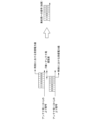
- 11 is a diagram for explaining a method for calculating a delay time to be applied in an embodiment.
- FIG. 11A and 11B are diagrams for explaining the setting timing of a delay time to be applied in the embodiment.
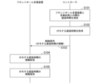
- FIG. 11 is a sequence diagram showing a flow of pre-processing performed by a communication system in an embodiment.
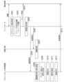
- 10 is a sequence diagram showing the flow of a switching process performed by a communication system according to an embodiment.
- FIG. FIG. 1 illustrates an example of a conventional communication system. A diagram for explaining an overview of the processing performed by the fronthaul multiplexing device.
- FIG. 1 illustrates an example of a conventional communication system.
- Fig. 1 is a diagram showing an example of the configuration of a communication system 100 according to an embodiment.
- the communication system 100 includes one or more antenna stations 10, a fronthaul multiplexer 20, an optical distribution unit 30, one or more aggregation stations 40, and a controller 50.
- Fig. 1 shows a case in which the communication system 100 includes three antenna stations 10-1 to 10-3 and two aggregation stations 40-1 to 40-2, but the number of antenna stations 10 and aggregation stations 40 is not particularly limited.
- antenna stations 10-1 to 10-3 will be referred to as antenna station 10 unless otherwise specified, and aggregation stations 40-1 to 40-2 will be referred to as aggregation station 40 unless otherwise specified.
- the direction from antenna station 10 to aggregation station 40 will be referred to as the uplink direction.
- Optical transmission paths connect the antenna stations 10-1, 10-2 and the fronthaul multiplexer 20, the fronthaul multiplexer 20 and the optical distribution unit 30, the optical distribution unit 30 and the aggregation stations 40-1, 40-2, and the antenna station 10-3 and the aggregation station 40-2.
- the optical transmission path is, for example, an optical fiber, and transmits optical signals. Electrical lines that transmit electrical signals connect the controller 50 and the fronthaul multiplexer 20, the controller 50 and the optical distribution unit 30, and the controller 50 and the aggregation stations 40-1, 40-2.
- antenna stations 10-1 and 10-2 are accommodated in a fronthaul multiplexing device 20, and antenna station 10-3 is accommodated in an aggregation station 40-2.
- the fronthaul multiplexing device 20 is accommodated in either aggregation station 40-1 or aggregation station 40-2 via an optical distribution unit 30.
- the optical distribution unit 30, aggregation station 40-1, and controller 50 are installed in base 1, and aggregation station 40-2 is installed in base 2.
- Base 1 and base 2 are installed in geographically separated locations.
- the antenna station 10 communicates with terminals located within cells S1, S2, and S3 that represent communication coverage areas.
- the antenna station 10-1 communicates with a terminal located within cell S1, for example.
- the antenna stations 10-2 and 10-3 communicate with terminals located in, for example, cells S2 and S3.
- the antenna station 10 receives an uplink signal transmitted from the terminal.
- the antenna station 10 is an RU in the mobile communication system.
- the antenna station 10 is one aspect of a terminal accommodating station.
- the fronthaul multiplexing device 20 behaves so that the multiple connected antenna stations 10 appear as a single antenna station 10 when viewed from the aggregation station 40.
- the fronthaul multiplexing device 20 receives uplink signals transmitted from each antenna station 10.
- the fronthaul multiplexing device 20 merges each received uplink signal by performing signal processing on signals that correspond to the same time. In this way, the fronthaul multiplexing device 20 generates a multiplexed signal.
- the fronthaul multiplexing device 20 acquires from the controller 50 information on the delay time to be imparted to the multiplexed signal when the connection is switched to the destination aggregate station 40 so that the delay with the currently connected aggregate station 40 does not change.
- the fronthaul multiplexing device 20 imparts the delay value indicated by the acquired delay time information to the multiplexed signal at the timing when the destination aggregate station 40 is switched. In this way, the fronthaul multiplexing device 20 adjusts the transmission timing of the multiplexed signal.
- the optical distribution unit 30 is an optical distribution device that has one or more first ports and multiple second ports, and outputs an optical signal input from one port from another port.
- the fronthaul multiplexing device 20 is connected to the first port of the optical distribution unit 30, and the aggregation stations 40-1 and 40-2 are connected to the second port of the optical distribution unit 30.
- the optical distribution unit 30 connects the first port to which the fronthaul multiplexing device 20 is connected to the second port to which the aggregation station 40 that accommodates the fronthaul multiplexing device 20 is connected under the control of the controller 50. In this way, the optical distribution unit 30 transfers the multiplexed signal transmitted from the fronthaul multiplexing device 20 to the aggregation station 40-1 or 40-2.
- the optical distribution unit 30 may be an optical switch, a multicast switch, or another switch.
- the aggregation station 40 processes the multiplexed signal transferred from the optical distribution unit 30 or transfers it to a higher level. Furthermore, the aggregation station 40 transitions to a sleep state in response to an instruction from the controller 50.
- the sleep state is a function that aims to save power by stopping some functions.
- the aggregation station 40 is a DU in the mobile communication system.
- the aggregation station 40-1 is an aspect of a first communication station
- the aggregation station 40-2 is an aspect of a second communication station.
- the aggregation station 40 is an aspect of a communication station.
- the controller 50 controls the entire communication system 100.
- the controller 50 acquires, from each of the multiple aggregation stations 40, judgment information used for sleep control of the aggregation stations 40.
- the judgment information is, for example, traffic volume, number of connected terminals, traffic flow, allocation amount, wireless quality information such as CQI (Channel Quality Indicator), priority information such as the communicated 5QI, and information on contracted services.
- CQI Channel Quality Indicator
- priority information such as the communicated 5QI
- information on contracted services information on contracted services.
- the judgment information is traffic volume.
- the controller 50 determines based on the judgment information that the aggregation station 40 (hereinafter referred to as the "sleep target aggregation station") that houses the fronthaul multiplexing device 20 can be put into a sleep state, it instructs the optical distribution unit 30 to switch. Furthermore, the controller 50 notifies the fronthaul multiplexing device 20 of delay time information. Before or after switching the optical distribution unit 30, the controller 50 instructs the sleep target aggregation station 40 to sleep.
- the aggregation station 40 hereinafter referred to as the "sleep target aggregation station”
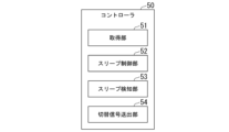
- FIG. 2 is a diagram showing an example of the configuration of a controller 50 in an embodiment.
- the controller 50 includes an acquisition unit 51, a sleep control unit 52, a sleep detection unit 53, and a switching signal transmission unit 54.
- the acquisition unit 51 acquires the judgment information from each of the multiple aggregation stations 40.
- the acquisition unit 51 acquires the judgment information from each of the multiple aggregation stations 40, for example, at a predetermined timing or periodically.
- the acquisition unit 51 outputs the acquired judgment information of each aggregation station 40 to the sleep control unit 52.
- the sleep control unit 52 judges whether or not the aggregation station 40 can sleep based on the judgment information of each aggregation station 40 acquired by the acquisition unit 51.
- the sleep control unit 52 judges, for example, whether or not the aggregation station to be put to sleep can sleep.
- the sleep control unit 52 judges that the sleep-target aggregate station can sleep if the period during which the traffic volume of the sleep-target aggregate station remains below the threshold continues for a predetermined period of time or longer and if other aggregate stations 40 can accommodate the fronthaul multiplexing device 20.
- the sleep control unit 52 determines that the sleep target aggregate station cannot sleep if the traffic volume of the sleep target aggregate station is equal to or greater than the threshold, or if the traffic volume of the sleep target aggregate station is less than the threshold but other aggregate stations 40 cannot accommodate the fronthaul multiplexing device 20.
- the sleep control unit 52 judges that the sleep target aggregate station can sleep if the number of connected terminals of the sleep target aggregate station (e.g., the number of antenna stations 10) falls below a predetermined standard and other aggregate stations 40 can accommodate the connected terminals of the sleep target aggregate station.
- the sleep control unit 52 determines that the sleep target aggregate station cannot sleep if the number of connected terminals of the sleep target aggregate station is equal to or greater than a predetermined criterion. Alternatively, the sleep control unit 52 may determine that the sleep target aggregate station cannot sleep if other aggregate stations 40 cannot accommodate the connected terminals of the sleep target aggregate station even if the number of connected terminals of the sleep target aggregate station falls below a predetermined criterion.
- the sleep control unit 52 determines that sleep is possible, it notifies the sleep detection unit 53 that the sleep target aggregation station will be put to sleep. Furthermore, if the sleep control unit 52 determines that sleep is possible, it sends a sleep instruction to the sleep target aggregation station.
- the sleep instruction is an instruction to execute a transition to a sleep state.
- the sleep detection unit 53 detects the transition of the sleep target aggregation station to a sleep state in response to a notification from the sleep control unit 52.
- the switching signal sending unit 54 sends to the optical distribution unit 30 a switching signal including an instruction to switch the accommodation of the fronthaul multiplexing device 20.
- the switching signal includes, for example, identification information of the aggregate station 40 to be switched to and information indicating the timing of switching. Furthermore, the switching signal sending unit 54 sends to the fronthaul multiplexing device 20 a control signal including information on the delay time.
- the switching signal sending unit 54 sends to the fronthaul multiplexing device 20 a control signal including information indicating the timing of switching of the optical distribution unit 30.
- the switching signal transmitter 54 acquires information on the delay time to be applied when the connection is switched to another aggregate station 40 (e.g., aggregate station 40-2) so that the delay between the aggregate station 40 (e.g., aggregate station 40-1) to which the fronthaul multiplexing device 20 is currently connected does not change.
- the switching signal transmitter 54 acquires, for example, the difference between a first delay time required for transfer between the fronthaul multiplexing device 20 and aggregate station 40-1 and a second delay time required for transfer between the fronthaul multiplexing device 20 and aggregate station 40-2 as the delay time to be applied. Note that if three or more aggregate stations 40 are provided, the switching signal transmitter 54 performs the same process.
- FIG. 3 is a diagram showing an example of the configuration of a fronthaul multiplexing device 20 in an embodiment.
- the fronthaul multiplexing device 20 includes a lower-order delay insertion unit 21, a signal merging unit 22, a switching signal processing unit 23, and an upper-order delay insertion unit 24.
- the lower-side delay insertion unit 21 receives each upstream signal output from each of the multiple antenna stations 10. Using each received upstream signal, the lower-side delay insertion unit 21 imparts a delay to some of the upstream signals so that they appear to have been received at the same time. The lower-side delay insertion unit 21 imparts a delay to the upstream signals according to the difference in distance, for example.
- the signal combining unit 22 multiplexes each upstream signal, including the upstream signal to which a delay has been applied by the lower-side delay insertion unit 21, to generate a multiplexed signal.
- the switching signal processing unit 23 receives a control signal transmitted from the controller 50.
- the switching signal processing unit 23 acquires delay time information contained in the received control signal and information indicating the switching timing of the optical distribution unit 30.
- the switching signal processing unit 23 switches the delay value imparted by the upper-side delay insertion unit 24 based on the switching timing of the optical distribution unit 30. For example, the switching signal processing unit 23 switches the delay value so that the upper-side delay insertion unit 24 imparts the delay value indicated by the delay time information to the switching timing of the optical distribution unit 30.
- the upper delay insertion unit 24 imparts the delay value switched by the switching signal processing unit 23 to the multiplexed signal output from the signal merging unit 22. Note that the upper delay insertion unit 24 does not need to impart a delay to the t term if the delay value has not been switched by the switching signal processing unit 23.
- FIG. 4 is a diagram for explaining a method for calculating the delay time to be applied in the embodiment.
- the switching signal sending unit 54 obtains the propagation delay time difference (upper side delay difference A in FIG. 4) by calculating the difference between the first delay time required for transfer between the fronthaul multiplexing device 20 and the aggregation station 40-1 and the second delay time required for transfer between the fronthaul multiplexing device 20 and the aggregation station 40-2.
- the fronthaul multiplexing device 20 adds a propagation delay time difference to the multiplexed signal and transmits the multiplexed signal to the post-switching aggregation station 40-2. Even if switching is made to aggregation station 40-2, which performs baseband signal processing at the same timing as aggregation station 40-1 due to time synchronization, the signal is transmitted just in time for the upstream baseband processing after switching, eliminating the need for another propagation delay that would accompany a link disconnection.
- loss associated with switching can be avoided (when A>B) by matching the additional insertion delay difference with the switching timing of the optical distribution unit 30. Note that loss can be reduced when A ⁇ B.
- the delay to the aggregation station 40 may be set to 0, but if it is set to be equal to or greater than the propagation time of the switching command from the controller 50, the delay difference and switching time B can be made to overlap.
- the switching signal transmission unit 54 of the controller 50 measures the delay time between the fronthaul multiplexing device 20 and each aggregate station 40 (step S101). For example, the switching signal transmission unit 54 measures a first delay time between the fronthaul multiplexing device 20 and aggregate station 40-1, and a second delay time between the fronthaul multiplexing device 20 and aggregate station 40-2.
- the switching signal transmitter 54 uses the measured delay time between the fronthaul multiplexer 20 and each aggregate station 40 to obtain a delay time to be applied when the connection is switched to another aggregate station 40 so that the delay between the aggregate station 40 to which the fronthaul multiplexer 20 is connected does not change (step S102). Specifically, the switching signal transmitter 54 obtains the delay time to be applied, which is the difference between the delay time of the aggregate station 40 to which the fronthaul multiplexer 20 is connected (e.g., a first delay time) and the delay time of the other aggregate station 40 (e.g., a second delay time).
- the switching signal transmitter 54 notifies the fronthaul multiplexer 20 of a control signal including the acquired information on the delay time to be imparted (step S103).
- the switching signal processor 23 of the fronthaul multiplexer 20 acquires the control signal sent from the controller 50.
- the switching signal processor 23 acquires the information on the delay time to be imparted contained in the acquired control signal (step S104).
- the switching signal processor 23 stores the acquired information on the delay time to be imparted in association with the identification information of the central station 40 (step S105).
- FIG. 7 is a sequence diagram showing the flow of the switching process performed by the communication system 100 in the embodiment.
- the aggregation stations 40-1 and 40-2 are described as an aggregation station group when no particular distinction is made.
- the fronthaul multiplexing device 20 is connected to the aggregation station 40-1 via the optical distribution unit 30.
- the acquisition unit 51 of the controller 50 acquires information on the traffic volume of each aggregate station 40 (step S201).
- the acquisition unit 51 outputs the acquired information on the traffic volume of each aggregate station 40 to the sleep control unit 52.
- the sleep control unit 52 judges whether or not to put the aggregate station 40 to sleep based on the traffic volume information of each aggregate station 40 output from the acquisition unit 51 (step S202). For example, it is assumed that the sleep control unit 52 judges that the aggregate station 40-1 can be put to sleep. In this case, the sleep control unit 52 transmits a sleep instruction to the aggregate station 40-1 (step S203). This allows the aggregate station 40-1 to transition to a sleep state.
- the sleep control unit 52 may transmit a sleep instruction to the aggregation station 40-1 after the optical distribution unit 30 makes the switch.
- the sleep control unit 52 notifies the sleep detection unit 53 that the aggregation station 40-1 will be put to sleep.
- the sleep detection unit 53 detects the sleep of the aggregation station 40-1 to which the fronthaul multiplexing device 20 is currently connected based on the notification from the sleep control unit 52.
- the sleep detection unit 53 determines the aggregation station 40 that will accommodate the fronthaul multiplexing device 20 that was connected to the aggregation station 40-1 (step S204).
- the sleep detection unit 53 has determined that the aggregation station 40-2 will accommodate the fronthaul multiplexing device 20 that was connected to the aggregation station 40-1.
- the method of determining the accommodation of the fronthaul multiplexing device 20 is not particularly limited.
- an aggregation station 40 that already accommodates devices other than the fronthaul multiplexing device 20 (e.g., an antenna station 10 that is not connected to the fronthaul multiplexing device 20) and can process the fronthaul multiplexing device 20 may be determined as the accommodation of the fronthaul multiplexing device 20. This makes it possible to aggregate multiple devices in a single aggregation station 40.
- the sleep detection unit 53 notifies the switching signal sending unit 54 of the determined accommodation destination.
- the switching signal sending unit 54 sends a control signal including information indicating the switching timing of the optical distribution unit 30 to the fronthaul multiplexing device 20 (step S205). Furthermore, the switching signal sending unit 54 sends a switching signal to the optical distribution unit 30 (step S206).
- the optical distribution unit 30 receives the switching signal sent from the controller 50.
- the optical distribution unit 30 performs switching at the timing included in the switching signal (step S207). For example, the optical distribution unit 30 performs switching at the timing included in the switching signal to connect the first port to which the fronthaul multiplexing device 20 is connected and the second port to which the aggregation station 40-2 is connected.
- the switching signal processing unit 23 of the fronthaul multiplexing device 20 receives the control signal sent from the controller 50.
- the switching signal processing unit 23 sets the delay value indicated by the delay time information in the upper-level delay insertion unit 24 (step S208).
- the delay value is switched so that the upper-level delay insertion unit 24 imparts the delay value indicated by the delay time information.
- the lower-side delay insertion unit 21 of the fronthaul multiplexing device 20 receives each upstream signal output from each of the multiple antenna stations 10 (step S209).
- the lower-side delay insertion unit 21 inserts a delay into a portion of each received upstream signal (step S210). Note that the insertion of delay is the same as in the past.
- the lower-side delay insertion unit 21 outputs each upstream signal, including the delayed upstream signal, to the signal combining unit 22.
- the signal combining unit 22 multiplexes each upstream signal, including the upstream signal to which a delay has been applied by the lower-side delay insertion unit 21, to generate a multiplexed signal (step S211).
- the signal combining unit 22 outputs the generated multiplexed signal to the upper-side delay insertion unit 24.
- the upper-side delay insertion unit 24 applies a delay value set by the switching signal processing unit 23 to the multiplexed signal output from the signal combining unit 22 (step S212).
- the upper-side delay insertion unit 24 then outputs the multiplexed signal to the optical distribution unit 30 after a delay time corresponding to the delay value has elapsed (step S213).
- the multiplexed signal input to the optical distribution unit 30 is transferred to the aggregation station 40-2, which is the new accommodation destination.
- the controller 50 sends a switching signal to the optical distribution unit 30, and includes a switching signal sending unit 54 that sends a control signal to the fronthaul multiplexing device 20 including information on the delay time to be added to the multiplexed signal by the fronthaul multiplexing device 20 so that the delay time does not change before and after switching the central station 40.
- the fronthaul multiplexing device 20 obtains information on the delay time to be added to the multiplexed signal included in the control signal from the controller 50 in advance, and includes a switching signal processing unit 23 that switches the delay value to be added to the multiplexed signal at the timing of switching the optical distribution unit 30, and an upper delay insertion unit 24 that adds the delay value switched by the switching signal processing unit 23 to the multiplexed signal.
- power saving measures can be applied in cases where power saving measures such as putting the aggregation station 40 to sleep cannot be applied because the allowable interruption time is limited.
- the controller 50 may be configured to wake up the sleeping aggregate station 40.
- the sleep control unit 52 judges whether or not the sleep of the aggregate station 40-1 needs to be woken up, for example, based on judgment information acquired from the aggregate station 40-2 that is not in a sleep state.
- the sleep control unit 52 judges that the sleep of the aggregate station 40-1 needs to be woken up when the traffic volume of the aggregate station 40-2 that is not in a sleep state becomes equal to or exceeds a predetermined threshold (for example, 50 percent of the traffic volume that can be processed by the aggregate station 40-2).
- the sleep control unit 52 determines that it is not necessary to wake up the aggregation station 40-1 from sleep. Note that, although the example described here uses the traffic volume as the judgment information, when other information is used as the judgment information, the judgment is based on other judgment criteria.
- the sleep control unit 52 determines that a sleep wakeup is necessary, it notifies the sleep detection unit 53 to wake up the sleeping aggregation station 40-1. Furthermore, if the sleep control unit 52 determines that a sleep wakeup is necessary, it transmits a sleep wakeup instruction to the sleeping aggregation station 40-1.
- the sleep wakeup instruction is an instruction for executing a return from the sleep state.
- the aggregation station 40-1 returns from the sleep state in response to receiving the sleep wakeup instruction transmitted from the controller 50.
- the sleep detection unit 53 detects the wake-up of the sleeping aggregation station 40-1 in response to a notification from the sleep control unit 52 indicating that the sleeping aggregation station 40-1 is to be woken up.
- the switching signal sending unit 54 sends a switching signal to the optical distribution unit 30 including an instruction to switch the accommodation of the fronthaul multiplexing device 20.
- the switching signal sending unit 54 sends a switching signal to the optical distribution unit 30 including an instruction to switch the accommodation of the fronthaul multiplexing device 20 to the aggregation station 40-1 that is returning from the sleep state.
- the switching signal transmission unit 54 sends a control signal including information indicating the switching timing of the optical distribution unit 30 to the fronthaul multiplexing device 20.
- the switching signal processing unit 23 of the fronthaul multiplexing device 20 receives the control signal sent from the controller 50. Based on the received control signal, the switching signal processing unit 23 sets the delay value to be set in the upper-side delay insertion unit 24 to the delay value before switching. For example, the switching signal processing unit 23 switches the delay value so that the upper-side delay insertion unit 24 imparts the delay value indicated by the delay time information to the switching timing of the optical distribution unit 30. This makes it possible to switch back to the state before switching.
- the communication system 100 may be configured to include a wireless controller that wirelessly communicates with the aggregate station 40.
- the wireless controller includes the acquisition unit 51 and sleep control unit 52 that the controller 50 includes, and the controller 50 does not include the acquisition unit 51 or the sleep control unit 52.
- the sleep control unit 52 of the wireless controller determines that sleep is possible, it notifies the controller 50 that the sleep target aggregate station will be put to sleep.
- the sleep detection unit 53 of the controller 50 detects the transition of the sleep target aggregate station to a sleep state. Thereafter, the same processing as in the above-mentioned embodiment is performed.
- At least some or all of the functional units of the fronthaul multiplexer 20 and the controller 50 are realized as software by a processor such as a CPU (Central Processing Unit) executing a program stored in a storage device having a non-volatile recording medium (non-transient recording medium) and in the storage unit.
- the program may be recorded on a computer-readable non-transient recording medium.
- Examples of computer-readable non-transient recording media include portable media such as flexible disks, optical magnetic disks, ROMs (Read Only Memory), and CD-ROMs (Compact Disc Read Only Memory), and storage devices such as hard disks built into computer systems.
- At least some or all of the functional units of the fronthaul multiplexer 20, or some or all of the functional units of the controller 50 may be realized using hardware including electronic circuits (electronic circuits or circuitry) using, for example, an LSI (Large Scale Integrated circuit), an ASIC (Application Specific Integrated Circuit), a PLD (Programmable Logic Device), or an FPGA (Field Programmable Gate Array).
- electronic circuits electronic circuits or circuitry
- LSI Large Scale Integrated circuit
- ASIC Application Specific Integrated Circuit
- PLD Programmable Logic Device
- FPGA Field Programmable Gate Array
- the present invention can be applied to a communication system equipped with a fronthaul multiplexing device.
Landscapes
- Engineering & Computer Science (AREA)
- Computer Networks & Wireless Communication (AREA)
- Signal Processing (AREA)
- Mobile Radio Communication Systems (AREA)
Abstract
Ce dispositif de commande est pourvu d'une unité de transmission de signal de commutation qui : transmet, à une unité de distribution optique, un signal de commutation comprenant une instruction pour réaliser une commutation d'une destination d'accueil d'un multiplexeur fronthaul,d'une première station de communication à une seconde station de communication, le multiplexeur fronthaul délivrant à une destination de distribution, par l'intermédiaire de l'unité de distribution optique, un signal multiple obtenu par multiplexage de signaux émis par une pluralité de stations d'accueil de terminal communiquant avec un terminal par réglage des synchronisations des signaux; et transmet, au multiplexeur fronthaul, un signal de commande comprenant des informations relatives à un temps de retard devant être conféré au signal multiple par le multiplexeur fronthaul, de telle sorte que le temps de retard ne change pas avant et après la commutation entre les stations de communication.
Priority Applications (2)
| Application Number | Priority Date | Filing Date | Title |
|---|---|---|---|
| PCT/JP2023/021175 WO2024252563A1 (fr) | 2023-06-07 | 2023-06-07 | Dispositif de commande, multiplexeur fronthaul, procédé de commutation de connexion et procédé de multiplexage |
| JP2025525529A JPWO2024252563A1 (fr) | 2023-06-07 | 2023-06-07 |
Applications Claiming Priority (1)
| Application Number | Priority Date | Filing Date | Title |
|---|---|---|---|
| PCT/JP2023/021175 WO2024252563A1 (fr) | 2023-06-07 | 2023-06-07 | Dispositif de commande, multiplexeur fronthaul, procédé de commutation de connexion et procédé de multiplexage |
Publications (1)
| Publication Number | Publication Date |
|---|---|
| WO2024252563A1 true WO2024252563A1 (fr) | 2024-12-12 |
Family
ID=93795399
Family Applications (1)
| Application Number | Title | Priority Date | Filing Date |
|---|---|---|---|
| PCT/JP2023/021175 Ceased WO2024252563A1 (fr) | 2023-06-07 | 2023-06-07 | Dispositif de commande, multiplexeur fronthaul, procédé de commutation de connexion et procédé de multiplexage |
Country Status (2)
| Country | Link |
|---|---|
| JP (1) | JPWO2024252563A1 (fr) |
| WO (1) | WO2024252563A1 (fr) |
Citations (2)
| Publication number | Priority date | Publication date | Assignee | Title |
|---|---|---|---|---|
| JP2019029842A (ja) * | 2017-07-31 | 2019-02-21 | 株式会社Nttドコモ | フロントホールマルチプレクサおよび無線通信システム |
| CN112996074A (zh) * | 2021-03-09 | 2021-06-18 | 中国联合网络通信集团有限公司 | 共享小区下的路由方法、装置、终端设备及存储介质 |
-
2023
- 2023-06-07 JP JP2025525529A patent/JPWO2024252563A1/ja active Pending
- 2023-06-07 WO PCT/JP2023/021175 patent/WO2024252563A1/fr not_active Ceased
Patent Citations (2)
| Publication number | Priority date | Publication date | Assignee | Title |
|---|---|---|---|---|
| JP2019029842A (ja) * | 2017-07-31 | 2019-02-21 | 株式会社Nttドコモ | フロントホールマルチプレクサおよび無線通信システム |
| CN112996074A (zh) * | 2021-03-09 | 2021-06-18 | 中国联合网络通信集团有限公司 | 共享小区下的路由方法、装置、终端设备及存储介质 |
Also Published As
| Publication number | Publication date |
|---|---|
| JPWO2024252563A1 (fr) | 2024-12-12 |
Similar Documents
| Publication | Publication Date | Title |
|---|---|---|
| AU621011B2 (en) | Improved base station for mobile radio telecommunications systems | |
| EP2190247B1 (fr) | Procédé de surveillance de cellules voisines et appareil pour terminal mobile à double position d'attente | |
| EP1060629B1 (fr) | Equilibrage de charges des appels en cours entre differents controleurs de stations de base | |
| CN101771591B (zh) | 一种rru与bbu环形组网下的业务传输方法及系统 | |
| EP1708369B1 (fr) | Communication double mode | |
| CN111031150B (zh) | 终端及终端的通信方法 | |
| US8909273B2 (en) | Wireless communication system, wireless communication method, terminal apparatus, and communication apparatus | |
| US6594475B1 (en) | Mobile battery discharge minimization in indoor wireless networks by antenna switching | |
| US20100048209A1 (en) | Wireless Communication Terminal Apparatus and Wireless Communication Method | |
| US20190069255A1 (en) | Synchronization method and apparatus | |
| WO2017089898A1 (fr) | Procédés et appareils de communication avec une cellule virtuelle, et système de communication associé | |
| KR20010043142A (ko) | 무선통신 시스템에서 소프트 핸드오프 사용을 제어하는방법 및 장치 | |
| EP2223432B1 (fr) | Systèmes et procédés pour réguler la tension de signaux utilisés pour commander les amplificateurs de puissance | |
| KR20010062845A (ko) | 이동통신 단말기에서 단속 모드 동작의 변환을 위한시스템 및 방법 | |
| US6728537B1 (en) | GPRS mobile paging method | |
| CN111405579A (zh) | 网络优化方法、装置、存储介质及电子设备 | |
| KR19990086942A (ko) | 무선 인터페이스 시뮬레이션 장치 및 방법 | |
| EP2154793A2 (fr) | Système de commutation dynamique et procédé entre une transmission d'antenne simple et multiple | |
| WO2024252566A1 (fr) | Dispositif de commande, multiplexeur fronthaul, procédé de commutation de connexion et multiplexeur | |
| US11916837B2 (en) | Distributed station, aggregation station, terminal, and communication method | |
| KR100353800B1 (ko) | 무선 가입자망 시스템에서 기지국과 기지국 제어기간 이1 인터페이스보드 이중화장치 및 그를 이용한 이중화 절체 방법 | |
| CN100433575C (zh) | 一种基站反向链路的冗余备份系统及射频切换装置 | |
| KR101690286B1 (ko) | 액티브 안테나 시스템 기반의 셀 최적화 방법과, 이 방법을 수행하는 디지털 신호 처리 장치 및 무선 통신 시스템 | |
| CN115136502A (zh) | 无线电通信的方法和装置 | |
| US20260005925A1 (en) | System and method for supporting a 4g combo cell |
Legal Events
| Date | Code | Title | Description |
|---|---|---|---|
| 121 | Ep: the epo has been informed by wipo that ep was designated in this application |
Ref document number: 23940665 Country of ref document: EP Kind code of ref document: A1 |
|
| ENP | Entry into the national phase |
Ref document number: 2025525529 Country of ref document: JP Kind code of ref document: A |
|
| NENP | Non-entry into the national phase |
Ref country code: DE |
|
| 122 | Ep: pct application non-entry in european phase |
Ref document number: 23940665 Country of ref document: EP Kind code of ref document: A1 |