WO2024252566A1 - 制御装置、フロントホール多重装置、接続切替方法及び多重方法 - Google Patents
制御装置、フロントホール多重装置、接続切替方法及び多重方法 Download PDFInfo
- Publication number
- WO2024252566A1 WO2024252566A1 PCT/JP2023/021182 JP2023021182W WO2024252566A1 WO 2024252566 A1 WO2024252566 A1 WO 2024252566A1 JP 2023021182 W JP2023021182 W JP 2023021182W WO 2024252566 A1 WO2024252566 A1 WO 2024252566A1
- Authority
- WO
- WIPO (PCT)
- Prior art keywords
- station
- optical distribution
- distribution unit
- sleep
- unit
- Prior art date
- Legal status (The legal status is an assumption and is not a legal conclusion. Google has not performed a legal analysis and makes no representation as to the accuracy of the status listed.)
- Ceased
Links
Images






Classifications
-
- H—ELECTRICITY
- H04—ELECTRIC COMMUNICATION TECHNIQUE
- H04W—WIRELESS COMMUNICATION NETWORKS
- H04W52/00—Power management, e.g. Transmission Power Control [TPC] or power classes
-
- H—ELECTRICITY
- H04—ELECTRIC COMMUNICATION TECHNIQUE
- H04W—WIRELESS COMMUNICATION NETWORKS
- H04W92/00—Interfaces specially adapted for wireless communication networks
Definitions
- the present invention relates to a control device, a fronthaul multiplexing device, a connection switching method, and a multiplexing method.
- FIG. 11 is a diagram showing an example of a conventional communication system S.
- the communication system S comprises multiple antenna stations 1-1, 1-2, a fronthaul multiplexer 2, and an aggregate station 3.
- the antenna stations 1-1, 1-2 are RUs (Radio Units) in the mobile communication system.
- the aggregate station 3 is a CU/DU (Central Unit/Distributed Unit) in the mobile communication system.
- a device called a fronthaul multiplexer (FHM) 2 is placed between the antenna stations 1-1, 1-2 installed at different locations.
- FHM fronthaul multiplexer
- the fronthaul multiplexing device 2 behaves so that the multiple antenna stations 1-1, 1-2 connected to it appear as a single antenna station when viewed from the aggregation station 3. Specifically, the fronthaul multiplexing device 2 performs signal processing on the uplink signals received from the multiple antenna stations 1-1, 1-2 that correspond to the same time, and merges the signals. Depending on the distance between the fronthaul multiplexing device 2 and each antenna station 1-1, 1-2, the time at which each uplink signal is received by the fronthaul multiplexing device 2 differs. For this reason, the fronthaul multiplexing device 2 applies a delay to the received uplink signals according to the distance difference, then merges the signals and performs signal processing.
- FIG. 12 is a diagram for explaining an overview of the processing performed by the fronthaul multiplexing device 2.
- the uplink signal transmitted from the antenna station 1-1 arrives at the fronthaul multiplexing device 2 before the uplink signal transmitted from the antenna station 1-2.
- the fronthaul multiplexing device 2 synchronizes the reception times of the uplink signals transmitted from each of the antenna stations 1-1 and 1-2 by adding a delay to the uplink signal transmitted from the antenna station 1-1.
- the fronthaul multiplexing device 2 then generates a multiplexed signal by multiplexing the uplink signals transmitted from each of the antenna stations 1-1 and 1-2.
- the fronthaul multiplexing device 2 By using the fronthaul multiplexing device 2 in this way, it is possible to reduce the number of ports required for the aggregation station 3 and the number of fibers required between the fronthaul multiplexing device 2 and the aggregation station 3.
- the fronthaul multiplexing device 2 adds (or selects) the signals (quantized received power) received by the antennas to make them appear as if they are received from a single antenna. For this reason, adjustments must be made to prevent deviations in the sampling time during addition.
- Fronthaul multiplexing devices 2 for 5G are also being developed.
- the present invention aims to provide technology that can reduce the power consumption of the entire system.
- One aspect of the present invention is a control device that includes: a sleep detection unit that detects a transition to a sleep state of a communication station connected to a first path that does not pass through a front-haul multiplexing device that multiplexes and outputs signals output from one or more terminal accommodating stations via an optical distribution unit that outputs signals output from the one or more terminal accommodating stations to another path, among a plurality of communication stations that accommodate one or more terminal accommodating stations that communicate with a terminal; and a switching signal transmission unit that, when the sleep detection unit detects the transition of the communication station to the sleep state, transmits a switching signal to the optical distribution unit to instruct the optical distribution unit to switch the terminal accommodating station accommodated in the communication station that has transitioned to the sleep state to be accommodated in a communication station connected to a second path via the optical distribution unit and the front-haul multiplexing device.
- One aspect of the present invention is a fronthaul multiplexing device in a communication system including a plurality of terminal accommodating stations that communicate with terminals, an optical distribution unit that outputs each signal output from the plurality of terminal accommodating stations to an allocation destination, and a fronthaul multiplexing device that multiplexes and outputs each signal output from the optical distribution unit, the fronthaul multiplexing device including a switching notification receiving unit that receives information on the delay time required for transfer between the terminal accommodating station to be the target of connection switching and the optical distribution unit, and information on the terminal accommodating station to be the target of connection switching, a delay adjustment unit that adjusts the timing of sending each signal received via the optical distribution unit by adding a delay to the signal output from the terminal accommodating station specified by the information on the terminal accommodating station to be the target of connection switching based on the delay time information received by the switching notification receiving unit, and a signal merging unit that multiplexes and outputs the signal output from the terminal accommodating station adjusted by the delay adjustment unit and the signal output from another terminal accommodating station.
- One aspect of the present invention is a connection switching method that detects a transition to a sleep state of a communication station connected to a first path that does not go through a front-haul multiplexing device that multiplexes and outputs signals output from one or more terminal accommodating stations via an optical distribution unit that outputs signals output from the one or more terminal accommodating stations to another path, among multiple communication stations that accommodate one or more terminal accommodating stations that communicate with a terminal, and when the transition of the communication station to the sleep state is detected, sends a switching signal to the optical distribution unit to instruct the optical distribution unit to switch the terminal accommodating station accommodated in the communication station that has transitioned to the sleep state to be accommodated in a communication station connected to a second path via the optical distribution unit and the front-haul multiplexing device.
- One aspect of the present invention is a multiplexing method performed by a fronthaul multiplexing device in a communication system including a plurality of terminal accommodating stations that communicate with terminals, an optical distribution unit that outputs each signal output from the plurality of terminal accommodating stations to an allocation destination, and a fronthaul multiplexing device that multiplexes and outputs each signal output from the optical distribution unit, the multiplexing method receiving information on the delay time required for transfer between the terminal accommodating station to be the target of connection switching and the optical distribution unit, and information on the terminal accommodating station to be the target of connection switching, and adjusting the timing of sending each signal received via the optical distribution unit by imparting a delay to the signal output from the terminal accommodating station specified by the information on the terminal accommodating station to be the target of connection switching based on the received delay time information, and multiplexing and outputting the adjusted signal output from the signal output from the other terminal accommodating station.
- This invention makes it possible to reduce the power consumption of the entire system.
- FIG. 1 is a diagram illustrating an example of the configuration of a communication system according to a first embodiment.
- 4 is a diagram illustrating an example of the configuration of a light distribution unit connection table in the first embodiment.
- FIG. 5A and 5B are diagrams for explaining switching of connection relationships of light distribution units in the first embodiment.
- FIG. 2 is a sequence diagram showing a processing flow of the communication system according to the first embodiment.
- FIG. 11 is a diagram illustrating an example of the configuration of a communication system according to a modified example of the first embodiment.
- 13A and 13B are diagrams for explaining switching of the connection relationship of the light distribution unit in the second embodiment.
- FIG. 13 is a diagram illustrating an example of the configuration of a communication system according to a third embodiment.
- FIG. 13 is a diagram illustrating an example of the configuration of a light distribution unit connection table in the third embodiment.
- FIG. 13 is a diagram illustrating an example of a configuration of an insertion delay table in the third embodiment.
- 13 is a diagram for explaining switching of the connection relationship of the light distribution unit in the third embodiment.
- FIG. FIG. 1 illustrates an example of a conventional communication system. A diagram for explaining an overview of the processing performed by the fronthaul multiplexing device.
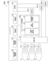
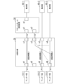
- FIG. 1 is a diagram showing a configuration example of a communication system 100 in the first embodiment.
- the communication system 100 includes one or more antenna stations 10, an optical distribution unit 20, a fronthaul multiplexing device 30, one or more aggregation stations 40, and a controller 50.
- Fig. 1 shows a case where the communication system 100 includes two antenna stations 10-1 to 10-2 and two aggregation stations 40-1 to 40-2, but the number of antenna stations 10 and aggregation stations 40 is not particularly limited.
- antenna stations 10-1 to 10-2 will be referred to as antenna station 10 unless otherwise specified, and aggregation stations 40-1 to 40-2 will be referred to as aggregation station 40 unless otherwise specified.
- the direction from antenna station 10 to aggregation station 40 will be referred to as the uplink direction.
- Optical transmission paths connect the antenna stations 10-1, 10-2 and the optical distribution unit 20, the optical distribution unit 20 and the fronthaul multiplexing device 30, the fronthaul multiplexing device 30 and the aggregation station 40-1, and the optical distribution unit 20 and the aggregation station 40-2.
- the optical transmission path is, for example, an optical fiber, and transmits optical signals.
- the controller 50 and the optical distribution unit 20, and the controller 50 and the aggregation stations 40-1, 40-2 are connected by electrical lines that transmit electrical signals.
- the antenna station 10-1 is accommodated in the aggregation station 40-1 via the optical distribution unit 20 and the fronthaul multiplexing device 30, and the antenna station 10-2 is accommodated in the aggregation station 40-2 via the optical distribution unit 20.
- the fronthaul multiplexing device 30 is accommodated in the aggregation station 40-1.
- the optical distribution unit 20 is an optical distribution device that has a plurality of first ports and a plurality of second ports, and outputs an optical signal input from one port from another port.
- a plurality of antenna stations 10 are connected to the plurality of first ports of the optical distribution unit 20, and a front-haul multiplexing device 30 and an aggregation station 40-2 are connected to the plurality of second ports of the optical distribution unit 20.
- the optical distribution unit 20 switches the connection so that each antenna station 10 is accommodated in the front-haul multiplexing device 30 according to the control of the controller 50.
- the optical distribution unit 20 switches the first port to which the antenna station 10-2 is connected from the second port to which the aggregation station 40-2 is connected to the second port to which the front-haul multiplexing device 30 is connected. In this way, the optical distribution unit 20 accommodates each antenna station 10 in the front-haul multiplexing device 30.
- the optical distribution unit 20 may be an optical switch, a multicast switch, or another switch.
- the fronthaul multiplexing device 30 behaves so that the multiple connected antenna stations 10 appear as a single antenna station 10 when viewed from the aggregation station 40.
- the fronthaul multiplexing device 30 receives uplink signals transmitted from each antenna station 10.
- the fronthaul multiplexing device 30 merges each received uplink signal by performing signal processing on signals that correspond to the same time. In this way, the fronthaul multiplexing device 30 generates a multiplexed signal.
- the fronthaul multiplexing device 30 outputs the generated multiplexed signal to the aggregation station 40-1.
- the aggregation station 40-1 processes the multiplexed signal output from the fronthaul multiplexer 30 or forwards it to a higher level. In this way, the aggregation station 40-1 is connected to a path that passes through the optical distribution unit 20 and the fronthaul multiplexer 30.
- the aggregation station 40-2 processes the upstream signal transferred from the optical distribution unit 20 or transfers it to a higher level. In this way, the aggregation station 40-2 is connected to a route that does not go through the fronthaul multiplexer 30 via the optical distribution unit 20. Furthermore, the aggregation station 40-2 goes into a sleep state in response to an instruction from the controller 50.
- the sleep state is a function that aims to save power by stopping some functions.
- the aggregation stations 40-1 and 40-2 are DUs in the mobile communication system.
- the aggregation station 40 is one aspect of a communication station.
- the controller 50 controls the entire communication system 100.
- the controller 50 acquires, from each of the multiple aggregation stations 40, judgment information used for sleep control of the aggregation stations 40.
- the judgment information is, for example, traffic volume, number of connected terminals, traffic flow, allocation amount, wireless quality information such as CQI (Channel Quality Indicator), priority information such as the communicated 5QI, and information on contracted services.
- CQI Channel Quality Indicator
- priority information such as the communicated 5QI
- information on contracted services information on contracted services.
- the judgment information is traffic volume.
- the controller 50 determines based on the judgment information that the aggregation station 40 to be put to sleep (hereinafter referred to as the "sleep target aggregation station") can be put into a sleep state, it instructs the optical distribution unit 20 to switch.
- the sleep target aggregation station is, for example, an aggregation station 40 (e.g., aggregation station 40-2) that is not connected to a route via the fronthaul multiplexing device 30.
- the controller 50 instructs the sleep target aggregation station to sleep before or after switching the optical distribution unit 20.
- the fronthaul multiplexing device 30 has a lower-order delay insertion unit 31 and a signal merging unit 32.
- the lower-side delay insertion unit 31 receives each upstream signal transferred from the optical distribution unit 20.
- the lower-side delay insertion unit 31 imparts a delay to at least some of the received upstream signals so that the signals are received at the same time.
- imparting a delay means inserting a delay into the signal to delay it.
- the lower-side delay insertion unit 31 imparts a delay to the upstream signal according to the distance difference, for example.
- the signal merging unit 32 multiplexes each upstream signal, including the upstream signal to which a delay has been applied by the lower-order delay insertion unit 31, to generate a multiplexed signal.
- the controller 50 includes an acquisition unit 51, a sleep control unit 52, a sleep detection unit 53, and a switching signal transmission unit 54.
- the acquisition unit 51 acquires the judgment information from each of the multiple aggregation stations 40.
- the acquisition unit 51 acquires the judgment information from each of the multiple aggregation stations 40, for example, at a predetermined timing or periodically.
- the acquisition unit 51 outputs the acquired judgment information of each aggregation station 40 to the sleep control unit 52.
- the sleep control unit 52 judges whether or not the aggregation station 40 can sleep based on the judgment information of each aggregation station 40 acquired by the acquisition unit 51.
- the sleep control unit 52 judges, for example, whether or not the aggregation station to be put to sleep can sleep.
- the sleep control unit 52 judges that the sleep target aggregate station can sleep if the period during which the traffic volume of the sleep target aggregate station remains below the first threshold continues for a predetermined period or more and other aggregate stations 40 can accommodate the traffic of the sleep target aggregate station.
- the sleep control unit 52 determines that the sleep target aggregate station cannot sleep when the traffic volume of the sleep target aggregate station is equal to or greater than the first threshold. Alternatively, the sleep control unit 52 may determine that the sleep target aggregate station cannot sleep when the period during which the traffic volume of the sleep target aggregate station is less than the first threshold does not continue for a predetermined period or more. Alternatively, the sleep control unit 52 may determine that the sleep target aggregate station cannot sleep when other aggregate stations 40 cannot accommodate the traffic of the sleep target aggregate station even if the period during which the traffic volume of the sleep target aggregate station is less than the first threshold continues for a predetermined period or more.
- the sleep control unit 52 judges that the sleep target aggregate station can sleep if the number of connected terminals of the sleep target aggregate station (e.g., the number of antenna stations 10) falls below a predetermined standard and other aggregate stations 40 can accommodate the connected terminals of the sleep target aggregate station.
- the sleep control unit 52 determines that the sleep target aggregate station cannot sleep if the number of connected terminals of the sleep target aggregate station is equal to or greater than a predetermined criterion. Alternatively, the sleep control unit 52 may determine that the sleep target aggregate station cannot sleep if other aggregate stations 40 cannot accommodate the connected terminals of the sleep target aggregate station even if the number of connected terminals of the sleep target aggregate station falls below a predetermined criterion.
- the sleep control unit 52 determines that sleep is possible, it notifies the sleep detection unit 53 that the sleep target aggregation station will be put to sleep. Furthermore, if the sleep control unit 52 determines that sleep is possible, it sends a sleep instruction to the sleep target aggregation station.
- the sleep instruction is an instruction to execute a transition to a sleep state.
- the sleep detection unit 53 detects the transition of the sleep target aggregation station to the sleep state in response to a notification from the sleep control unit 52.
- the sleep detection unit 53 detects the transition to the sleep state of, for example, aggregation station 40-2, which is connected via the optical distribution unit 20 to a route that does not go through the fronthaul multiplexing device 30.
- the switching signal sending unit 54 sends a switching signal including an instruction to switch the accommodation of the antenna station 10 to the optical distribution unit 20.
- the switching signal includes, for example, information indicating the port to which the switching destination aggregation station 40 is connected.
- the switching signal sending unit 54 obtains information to be included in the switching signal, for example, from the optical distribution unit connection table.
- the optical distribution unit connection table is a table in which information regarding the connection of the optical distribution unit 20 is registered. Details of the optical distribution unit connection table will be described later.
- the optical distribution unit connection table is stored in a memory not shown.
- the switching signal sending unit 54 detects that the sleep target aggregate station has transitioned to a sleep state, it sends a switching signal to the optical distribution unit 20 to instruct the switching so that the antenna station 10 accommodated in the sleep target aggregate station is accommodated in the aggregate station 40 that is connected to the path via the optical distribution unit 20 and the fronthaul multiplexing device 30.
- FIG. 2 is a diagram showing an example of the configuration of the optical distribution unit connection table in the first embodiment.
- the optical distribution unit connection table has a plurality of records in which information related to the connection of the optical distribution unit 20 is registered. Each record has values for lower device, lower device connection port, upper device, upper device connection port, port used during sleep, central station used during sleep, port used during sleep wake-up, and central station compatible during sleep wake-up.
- the lower device represents a lower device connected to the optical distribution unit 20.
- the lower device connected to the optical distribution unit 20 is, for example, the antenna station 10.
- the lower device connection port represents the first port of the optical distribution unit 20 to which the lower device is connected.
- the higher-level device refers to a higher-level device connected to the optical distribution unit 20.
- the higher-level device connected to the optical distribution unit 20 is, for example, the aggregation station 40.
- the higher-level device connection port refers to the second port of the optical distribution unit 20 to which the higher-level device is connected.
- the port used during sleep refers to the second port of the optical distribution unit 20 used as the connection destination of the antenna station 10 when the aggregation station 40 is in sleep mode.
- the aggregation station used during sleep refers to the aggregation station 40 used as the connection destination of the antenna station 10 when the aggregation station 40 is in sleep mode.
- the port used during sleep release refers to the second port of the optical distribution unit 20 used as the connection destination of the antenna station 10 when the aggregation station 40 is released from sleep mode.
- the aggregation station compatible during sleep release refers to the aggregation station 40 used as the connection destination of the antenna station 10 when the aggregation station 40 is released from sleep mode.
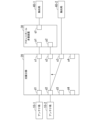
- FIG. 3 is a diagram for explaining switching of the connection relationship of the optical distribution unit 20 in the first embodiment.
- the optical distribution unit 20 has four first ports d1 to d4 and four second ports u1 to u4, and the fronthaul multiplexing device 30 has two first ports p1 to p2 and one second port q1.
- the number of ports provided in the optical distribution unit 20 and the fronthaul multiplexing device 30 is not limited to the example shown in FIG. 3.
- the antenna station 10-1 is connected to the first port d1 of the optical distribution unit 20
- the antenna station 10-2 is connected to the first port d2 of the optical distribution unit 20
- the fronthaul multiplexing device 30 is connected to the second ports u1 and u2 of the optical distribution unit 20
- the aggregation station 40-2 is connected to the second port u3 of the optical distribution unit 20.
- the optical distribution unit 20 is connected to the first ports p1 and p2 of the fronthaul multiplexing device 30, and the aggregation station 40-1 is connected to the second port q1 of the fronthaul multiplexing device 30.
- the first port d1 is connected to the second port u1
- the first port d2 is connected to the second port u3.
- the switching signal transmission unit 54 refers to the optical distribution unit connection table and determines that the aggregation station 40-2 is connected to the second port u3 of the optical distribution unit 20. Furthermore, the switching signal transmission unit 54 determines that the antenna station 10-2 accommodated in the aggregation station 40-2 is connected to the first port d2 of the optical distribution unit 20.
- the switching signal sending unit 54 refers to the items of the port used during sleep and the aggregation station used during sleep in the optical distribution unit connection table, and finds out that when the aggregation station 40-2 goes to sleep, the connection destination of the antenna station 10-2 is the aggregation station 40-1, and that the second port u2 of the optical distribution unit 20 toward the aggregation station 40-1 is used.
- the switching signal sending unit 54 generates a switching signal that instructs switching the connection from the first port d2 of the optical distribution unit 20 to the second port u3 of the optical distribution unit 20 to the connection from the first port d2 of the optical distribution unit 20 to the second port u2 of the optical distribution unit 20.
- the switching signal sending unit 54 sends the generated switching signal to the optical distribution unit 20.
- the optical distribution unit 20 switches the connection so that the first port d2 and the second port u2 are connected, as shown by the dotted line in FIG. 3.
- FIG. 4 is a sequence diagram showing the flow of processing in the communication system 100 in the first embodiment.
- the aggregation stations 40-1 and 40-2 are collectively referred to as an aggregation station group, but will be described as aggregation station 40-1 or 40-2 as necessary.
- the antenna station 10-1 is connected to the aggregation station 40-1 via the optical distribution unit 20 and the fronthaul multiplexer 30, and the antenna station 10-2 is directly connected to the aggregation station 40-2 via the optical distribution unit 20.
- the total traffic volume passing through the aggregation station 40-2 is 10% or more of the amount that the aggregation station 40-2 can process (for example, 1 Gbps).
- the acquisition unit 51 of the controller 50 acquires information on the traffic volume of each aggregation station 40 (step S101). It is assumed that the number of terminal devices connected to the aggregation station 40-2 via the antenna station 10-2 has increased to two before the acquisition unit 51 acquires the traffic volume information of each aggregation station 40. As a result, it is assumed that the average traffic flowing through the aggregation station 40-2 is 5% of the traffic that can be processed by the aggregation stations 40-1 and 40-2, or less than 50 Mbps.
- the acquisition unit 51 outputs the acquired traffic volume information of each aggregation station 40 to the sleep control unit 52.
- the sleep control unit 52 determines whether or not to put the aggregate station 40 to sleep based on the traffic volume information of each aggregate station 40 output from the acquisition unit 51 (step S102). For example, the sleep control unit 52 determines whether or not to put the aggregate station 40-2 to sleep based on the traffic volume information of the aggregate station 40-2. Here, it is assumed that the sleep control unit 52 determines that the aggregate station 40-2 can sleep. In this case, the sleep control unit 52 transmits a sleep instruction to the aggregate station 40-2 (step S203). This allows the aggregate station 40-2 to transition to a sleep state.
- the sleep control unit 52 may transmit a sleep instruction to the aggregation station 40-2 after the optical distribution unit 20 performs the switching.
- the sleep control unit 52 notifies the sleep detection unit 53 that the aggregation station 40-2 will be put to sleep.
- the sleep detection unit 53 detects the transition of the aggregation station 40-2 to the sleep state based on the notification from the sleep control unit 52.
- the sleep detection unit 53 determines that switching is necessary (step S104).
- the sleep detection unit 53 notifies that the connection of the optical distribution unit 20 needs to be switched and that the aggregation station 40-2 will transition to the sleep state.
- the switching signal sending unit 54 generates a switching signal in response to a notification from the sleep detection unit 53. Specifically, the switching signal sending unit 54 refers to the optical distribution unit connection table and generates a switching signal that instructs switching the connection from the first port d2 of the optical distribution unit 20 to the second port u3 of the optical distribution unit 20 to a connection from the first port d2 of the optical distribution unit 20 to the second port u2 of the optical distribution unit 20. The switching signal sending unit 54 transmits the generated switching signal to the optical distribution unit 20 (step S105).
- the optical distribution unit 20 receives the switching signal sent from the controller 50.
- the optical distribution unit 20 switches the connection between the ports based on the received switching signal (step S106). For example, the optical distribution unit 20 switches the connection so that the first port d2 and the second port u2 are connected. By switching the connection, the antenna stations 10-1 and 10-2 are accommodated in the aggregation station 40-1. After that, it is assumed that upstream signals are transmitted from each of the antenna stations 10-1 and 10-2.
- the optical distribution unit 20 inputs the upstream signals transmitted from the antenna stations 10-1 and 10-2 from a first port, and outputs the input upstream signals from a second port.
- the first ports of the optical distribution unit 20 to which the antenna stations 10-1 and 10-2 are connected are connected to a second port to which the fronthaul multiplexing device 30 is connected. As a result, each upstream signal input to the optical distribution unit 20 is forwarded to the fronthaul multiplexing device 30.
- the fronthaul multiplexing device 30 receives each upstream signal transferred from the optical distribution unit 20.
- the distance from the antenna station 10-1 to the fronthaul multiplexing device 30 is often different from the distance from the antenna station 10-2 to the fronthaul multiplexing device 30, and the antenna stations 10-1 and 10-2 also transmit upstream signals at different times. Therefore, the upstream signals transmitted from the antenna stations 10-1 and 10-2 are received at different times by the fronthaul multiplexing device 30.
- the lower-side delay insertion unit 31 of the fronthaul multiplexing device 30 inserts a delay into a portion of each received upstream signal (step S108).
- the delay insertion is the same as in the past.
- the lower-side delay insertion unit 31 outputs each upstream signal, including the upstream signal to which a delay has been applied, to the signal combining unit 32.
- the signal combining unit 32 multiplexes each upstream signal, including the upstream signal to which a delay has been applied by the lower-side delay insertion unit 31, to generate a multiplexed signal (step S109).
- the signal combining unit 32 outputs the generated multiplexed signal to the aggregation station 40-1 (step S110).
- the aggregation station 40-1 receives the multiplexed signal output from the optical distribution unit 20.
- the aggregation station 40-1 then processes the received multiplexed signal or transfers it to a higher level.
- the communication system 100 configured as described above includes a sleep detection unit 53 that detects the transition to a sleep state of the aggregate station 40-2, which is connected to the first route not via the fronthaul multiplexing device 30 via the optical distribution unit 20, among the multiple aggregate stations 40, and a switching signal transmission unit 54 that, when the sleep detection unit 53 detects the transition of the aggregate station 40-2 to the sleep state, transmits a switching signal to the optical distribution unit 20 instructing the optical distribution unit 20 to switch the antenna station 10-2 accommodated in the aggregate station 40-2 that has transitioned to the sleep state to be accommodated in the aggregate station 40 connected to the second route via the optical distribution unit 20 and the fronthaul multiplexing device 30.
- the connection is switched so that the antenna station 10 connected to the aggregation station 40 capable of sleep is accommodated in the aggregation station 40 connected to the fronthaul multiplexer 30.
- delay insertion and signal merging are performed through the fronthaul multiplexer 30, so that the signals of the antenna stations 10-1 and 10-2 are multiplexed and accommodated in one port of the aggregation station 40-1.
- the signal processing of the antenna station 10 can be aggregated in the aggregation station 40 connected to the fronthaul multiplexer 30, which multiplexes the signals of multiple antenna stations 10. This eliminates the need to prepare additional ports or other aggregation stations 40 on the aggregation station 40-1 side. Therefore, the aggregation station 40-2 can be put to sleep, which makes it possible to reduce the power consumption of the entire system compared to switching the aggregation station 40 connected one-to-one to the antenna station 10.
- the switchover is performed when the load on the aggregation station 40 is low enough that it can go to sleep, the impact on users due to bandwidth depletion can be reduced even after aggregation via the fronthaul multiplexing device 30.
- FIG. 5 is a diagram showing a configuration example of a communication system 100a in a modified example of the first embodiment.
- the communication system 100a includes one or more antenna stations 10, an optical distribution unit 20, a fronthaul multiplexing device 30, one or more aggregation stations 40, a wireless controller 60, and an optical distribution unit controller 65.
- FIG. 5 shows a case in which the communication system 100a includes two antenna stations 10-1 to 10-2 and two aggregation stations 40-1 to 40-2, but the number of antenna stations 10 and aggregation stations 40 is not particularly limited.
- the communication system 100a differs from the communication system 100 in that it includes a wireless controller 60 and an optical distribution unit controller 65 instead of the controller 50.
- the rest of the configuration of the communication system 100a is the same as that of the communication system 100. The following mainly describes the differences.
- the wireless controller 60 communicates wirelessly with the aggregation station 40 and with the optical distribution unit controller 65.
- the wireless controller 60 includes an acquisition unit 51 and a sleep control unit 52.
- the acquisition unit 51 included in the wireless controller 60 wirelessly acquires the judgment information from each of the multiple aggregate stations 40.
- the acquisition unit 51 wirelessly acquires the judgment information from each of the multiple aggregate stations 40, for example, at a predetermined timing or periodically.
- the acquisition unit 51 outputs the acquired judgment information of each aggregate station 40 to the sleep control unit 52.
- the sleep control unit 52 included in the wireless controller 60 judges whether the aggregate station 40 can sleep based on the judgment information of each aggregate station 40 acquired by the acquisition unit 51.
- the sleep control unit 52 determines that sleep is possible, it notifies the optical distribution unit controller 65 by radio that the sleep target aggregation station is to be put to sleep. Furthermore, if the sleep control unit 52 determines that sleep is possible, it transmits a sleep instruction by radio to the sleep target aggregation station.
- the optical distribution unit controller 65 controls the optical distribution unit 20.
- the optical distribution unit controller 65 includes a sleep detection unit 53 and a switching signal transmission unit 54.
- the sleep detection unit 53 included in the optical distribution unit controller 65 detects the transition of the sleep target aggregation station to a sleep state in response to a notification from the wireless controller 60.
- the switching signal transmission unit 54 included in the optical distribution unit controller 65 transmits a switching signal to the optical distribution unit 20 when the sleep detection unit 53 detects the transition of the sleep target aggregation station to a sleep state.
- the switching operation of the optical distribution unit 20 by the switching signal transmission unit 54 is the same as the method shown in the first embodiment.
- Second Embodiment a configuration in the case where a sleeping aggregate station is released from sleep will be described.
- the system configuration and device configuration in the second embodiment are similar to those in the first embodiment.
- the difference from the first embodiment is the operation of the controller 50.
- the sleep control unit 52 determines whether or not it is necessary to wake up the sleeping aggregate station 40 based on the determination information of each aggregate station 40 acquired by the acquisition unit 51.
- the aggregate station 40 that is the target for sleep wakeup is referred to as the sleep wakeup target aggregate station.
- the sleep control unit 52 determines that the sleep release target aggregate station needs to be released when the traffic volume of the aggregate station 40 that is not in the sleep state is equal to or greater than the second threshold value. On the other hand, when the traffic volume of the aggregate station 40 that is not in the sleep state is less than the second threshold value, the sleep control unit 52 determines that the sleep release target aggregate station does not need to be released.
- the sleep control unit 52 judges that it is necessary to wake up the target aggregate station for sleep release when the number of connected terminals (e.g., the number of antenna stations 10) of the aggregate station 40 that is not in a sleep state is equal to or greater than a predetermined criterion. On the other hand, when the number of connected terminals of the aggregate station 40 that is not in a sleep state is less than the predetermined criterion, the sleep control unit 52 judges that it is not necessary to wake up the target aggregate station for sleep release.
- the number of connected terminals e.g., the number of antenna stations
- the sleep control unit 52 determines that a sleep wakeup is necessary, it notifies the sleep detection unit 53 that it will start waking up the aggregation station to be woken up. Furthermore, when the sleep control unit 52 determines that a sleep wakeup is necessary, it transmits a sleep wakeup instruction to the aggregation station to be woken up.
- the sleep wakeup instruction is an instruction to wake up the sleep state.
- the sleep detection unit 53 detects the start of sleep wakeup of the target aggregation station in response to a notification from the sleep control unit 52. For example, the sleep detection unit 53 detects the start of sleep wakeup of the aggregation station 40-2 that is connected via a route that does not go through the fronthaul multiplexing device 30 via the optical distribution unit 20.
- the switching signal sending unit 54 sends a switching signal including an instruction to switch the accommodation of the antenna station 10 to the optical distribution unit 20.
- the switching signal sending unit 54 obtains information to be included in the switching signal, for example, from the optical distribution unit connection table.
- the switching signal sending unit 54 detects the start of sleep wakeup of the target aggregation station to be woken up, it sends a switching signal to the optical distribution unit 20 to instruct the switching so that the antenna station 10 accommodated in the aggregation station 40 that is not asleep is accommodated in the aggregation station 40 that is connected via the optical distribution unit 20 to a route that does not go through the fronthaul multiplexing device 30.
- FIG. 6 is a diagram for explaining the switching of the connection relationship of the light distribution unit 20 in the second embodiment. What differs from FIG. 3 in that inside the light distribution unit 20, the first port d1 is connected to the second port u1, and the first port d2 is connected to the second port u2.
- the switching signal sending unit 54 refers to the optical distribution unit connection table and determines that the aggregation station 40-2 is connected to the second port u3 of the optical distribution unit 20. Furthermore, the switching signal sending unit 54 determines that the antenna station 10-2 is connected to the first port d2 of the optical distribution unit 20.
- the switching signal sending unit 54 refers to the items of the port used at sleep release and the corresponding central station at sleep release in the optical distribution unit connection table, and finds out that when the central station 40-2 wakes up from sleep, the connection destination of the antenna station 10-2 is the central station 40-2, and that the second port u3 of the optical distribution unit 20 toward the central station 40-2 is to be used. As a result, the switching signal sending unit 54 generates a switching signal that instructs switching the connection from the first port d2 of the optical distribution unit 20 to the second port u2 of the optical distribution unit 20 to the connection from the first port d2 of the optical distribution unit 20 to the second port u3 of the optical distribution unit 20. The switching signal sending unit 54 sends the generated switching signal to the optical distribution unit 20. As a result, the optical distribution unit 20 switches the connection so that the first port d2 and the second port u3 are connected, as shown by the dotted line in FIG. 6.
- the antenna station 10-2 is reconnected to the aggregation station 40-2, and is then able to use the frequency resources of the aggregation station 40-2 that are not shared with the aggregation station 40-1. Therefore, even if the number of accommodated terminals increases, or terminals with high communication volumes or terminals requiring low latency are accommodated, service requests can be satisfied.
- the controller 50 judges whether or not sleep is to be cancelled and issues a switching command to the optical distribution unit 20.
- the judgement of whether or not sleep is to be cancelled and the switching command to the optical distribution unit 20 may be performed by different devices.
- the communication system 100 in the second embodiment includes a wireless controller 60 and an optical distribution unit controller 65 instead of the controller 50, similar to the modified example of the first embodiment.
- the wireless controller 60 wirelessly communicates with the aggregation station 40 and with the optical distribution unit controller 65.
- the wireless controller 60 includes an acquisition unit 51 and a sleep control unit 52.
- the acquisition unit 51 included in the wireless controller 60 wirelessly acquires the judgment information from each of the multiple aggregation stations 40.
- the acquisition unit 51 wirelessly acquires the judgment information from each of the multiple aggregation stations 40, for example, at a predetermined timing or periodically.
- the acquisition unit 51 outputs the acquired judgment information of each aggregation station 40 to the sleep control unit 52.
- the sleep control unit 52 included in the wireless controller 60 judges whether or not the sleep of the aggregation station to be released from sleep is required based on the judgment information of each aggregation station 40 acquired by the acquisition unit 51. If the sleep control unit 52 judges that a sleep release is required, it notifies the optical distribution unit controller 65 wirelessly to start releasing the sleep of the aggregation station to be released from sleep. Furthermore, if the sleep control unit 52 judges that a sleep release is required, it wirelessly transmits a sleep release instruction to the aggregation station to be released from sleep.
- the optical distribution unit controller 65 controls the optical distribution unit 20.
- the optical distribution unit controller 65 includes a sleep detection unit 53 and a switching signal transmission unit 54.
- the sleep detection unit 53 included in the optical distribution unit controller 65 detects the start of sleep wakeup of the aggregation station to be woken up in response to a notification from the wireless controller 60.
- the switching signal transmission unit 54 included in the optical distribution unit controller 65 transmits a switching signal to the optical distribution unit 20 when the sleep detection unit 53 detects the start of sleep wakeup of the aggregation station to be woken up.
- the switching operation of the optical distribution unit 20 by the switching signal transmission unit 54 is the same as the method shown in the second embodiment.
- FIG. 7 is a diagram showing an example of the configuration of a communication system 100b in the third embodiment.
- the communication system 100b includes one or more antenna stations 10, an optical distribution unit 20, a fronthaul multiplexing device 30b, one or more aggregation stations 40, and a controller 50b.
- FIG. 7 shows a case in which the communication system 100b includes three antenna stations 10-1 to 10-3 and two aggregation stations 40-1 to 40-2, but the number of antenna stations 10 and aggregation stations 40 is not particularly limited.
- Optical transmission paths connect the antenna stations 10-1, 10-2, 10-3 and the optical distribution unit 20, the optical distribution unit 20 and the fronthaul multiplexing device 30b, the fronthaul multiplexing device 30b and the aggregation station 40-1, and the optical distribution unit 20 and the aggregation stations 40-2, 40-3.
- Electric lines that transmit electrical signals connect the controller 50b and the optical distribution unit 20, the controller 50b and the fronthaul multiplexing device 30b, and the controller 50b and the aggregation stations 40-1, 40-2.
- the antenna station 10-1 is accommodated in the aggregation station 40-1 via the optical distribution unit 20 and the fronthaul multiplexing device 30b, and the antenna stations 10-2 and 10-3 are accommodated in the aggregation stations 40-2 and 40-3 via the optical distribution unit 20.
- the fronthaul multiplexing device 30b is accommodated in the aggregation station 40-1.
- Communication system 100b differs from communication system 100 in that it has a fronthaul multiplexing device 30b and a controller 50b instead of the fronthaul multiplexing device 30 and the controller 50, and in that it has three antenna stations 10 and three aggregation stations 40.
- the rest of the configuration of communication system 100b is the same as that of communication system 100. The following will focus on the differences.
- the controller 50b controls the entire communication system 100b.
- the controller 50b acquires judgment information used for sleep control of the aggregation station 40 from each of the multiple aggregation stations 40. Furthermore, the controller 50b acquires in advance the delay time (hereinafter referred to as "lower delay time") from the antenna station 10 to which the connection destination is switched to the fronthaul multiplexing device 30b in response to the switching of the connection relationship by the optical distribution unit 20.
- the antenna station 10 to which the new connection destination is connected to the aggregation station 40 via the optical distribution unit 20 and the fronthaul multiplexing device 30 is the target for acquiring the lower delay time by the controller 50b.
- the antenna station 10 for example, the antenna station 10-1 that connects to the aggregation station 40 via the optical distribution unit 20 and the fronthaul multiplexing device 30 before the connection switching by the optical distribution unit 20, communication is being performed between the antenna station 10-1 and the aggregation station 40-1, and therefore the lower delay time between the antenna station 10-1 and the fronthaul multiplexing device 30b is measured.
- the antenna stations 10-2 and 10-3 are connected to the aggregation station 40, which is connected via the optical distribution unit 20 to a route that does not go through the fronthaul multiplexing device 30. Therefore, the lower-level delay times between the antenna stations 10-2 and 10-3 and the fronthaul multiplexing device 30b are not measured. Therefore, the antenna stations 10-2 and 10-3 are targets from which the controller 50b acquires the lower-level delay times. The controller 50b notifies the fronthaul multiplexing device 30b of the acquired lower-level delay time information. As a result, the fronthaul multiplexing device 30b reuses the value of the lower-level delay time notified by the controller 50b, and does not need to remeasure the delay time between the newly connected antenna station 10.
- the fronthaul multiplexing device 30b behaves so that the multiple connected antenna stations 10 appear as a single antenna station 10 when viewed from the aggregation station 40.
- the fronthaul multiplexing device 30b receives uplink signals transmitted from each antenna station 10.
- the fronthaul multiplexing device 30b merges each received uplink signal by performing signal processing on signals that correspond to the same time. In this way, the fronthaul multiplexing device 30b generates a multiplexed signal.
- the fronthaul multiplexing device 30b outputs the generated multiplexed signal to the aggregation station 40-1.
- the fronthaul multiplexing device 30b When applying a delay to each upstream signal, the fronthaul multiplexing device 30b obtains information on the lower-order delay time from the controller 50b in advance. The fronthaul multiplexing device 30b then obtains the delay time to be applied to the upstream signal transmitted from each antenna station 10 based on the obtained information on the lower-order delay time. As described above, the lower-order delay time is the delay time between the antenna station 10 and the fronthaul multiplexing device 30b.
- the fronthaul multiplexing device 30b adds or selects signals that correspond to the same time, so it obtains the delay time to be applied to each upstream signal for each upstream signal, taking the lower-order delay time into account, so that the upstream signals have the same delay. The fronthaul multiplexing device 30b can then merge each upstream signal by applying the obtained delay time to each upstream signal.
- the fronthaul multiplexing device 30b has a lower-order delay insertion unit 31b, a signal merging unit 32, and a switching notification receiving unit 33.
- the switching notification receiver 33 receives information on the lower delay time corresponding to the antenna station 10 (hereinafter referred to as the "antenna station to be switched") newly connected to the fronthaul multiplexing device 30b from the controller 50b. Based on the received information on the lower delay time and the insertion delay table, the switching notification receiver 33 acquires the delay time to be added to the upstream signal transmitted from each antenna station 10 connected to the fronthaul multiplexing device 30b.
- the delay time to be added to the upstream signal will be referred to as the insertion delay time.
- the insertion delay table is a table in which information on the insertion delay time is registered. Details of the insertion delay table will be described later.
- the insertion delay table is stored in a memory (not shown).
- the switching notification receiver 33 notifies the lower side delay insertion unit 31b of the acquired information on the insertion delay time of each antenna station 10.
- the lower-side delay insertion unit 31b receives each upstream signal transferred from the optical distribution unit 20.
- the lower-side delay insertion unit 31b imparts a delay value indicated by the delay time information notified by the switching notification receiving unit 33 to at least some of the received upstream signals. This allows the lower-side delay insertion unit 31b to treat each upstream signal transmitted from a different antenna station 10 as a signal received at the same time.
- the controller 50b includes an acquisition unit 51, a sleep control unit 52, a sleep detection unit 53, a switching signal transmission unit 54, and a delay time management unit 55.
- the delay time management unit 55 acquires information on the lower-level delay time corresponding to the antenna station to be switched to.
- the delay time management unit 55 may calculate the lower-level delay time from a measurement value using AMCC (Auxiliary Management and Control Channel), or may hold a value previously measured by the fronthaul multiplexer 30b.
- AMCC Advanced Management and Control Channel
- the delay time management unit 55 sends a delay measurement signal to the antenna station to be switched to, measures the propagation delay between the optical distribution unit 20 and the antenna station to be switched to, and holds a value obtained by halving the round-trip delay time as the one-way delay.
- the delay time management unit 55 notifies the switching notification receiving unit 33 of the fronthaul multiplexing device 30 that the switching target antenna station will be connected and provides information on the delay time corresponding to the connected switching target antenna station.
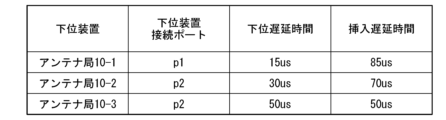
- FIG. 9 is a diagram showing an example of the configuration of an insertion delay table in the third embodiment.
- the insertion delay table has multiple records in which information related to the insertion delay time is registered. Each record has a lower device, a lower device connection port, a lower delay time, and an insertion delay time value.
- the lower device in the insertion delay table represents the lower device connected to the fronthaul multiplexing device 30b.
- the lower device connected to the fronthaul multiplexing device 30b is, for example, the antenna station 10.
- the lower device connection port represents the first port of the fronthaul multiplexing device 30b to which the lower device is connected.
- the lower delay time represents the delay time required for transmission between the antenna station 10 and the fronthaul multiplexing device 30b.
- the insertion delay time represents the delay time added to the upstream signal.
- the lower delay times from the antenna stations 10-1, 10-2, and 10-3 to the fronthaul multiplexing device 30b are 15 us, 30 us, and 50 us, respectively.
- the delay time management unit 55 obtains the insertion delay time based on the lower delay time so that the sum of the lower delay time and the insertion delay time is the same value (so that the delay is the same) for each of the antenna stations 10-1, 10-2, and 10-3.
- FIG. 9 shows an example in which the insertion delay time is obtained so that the total value is 100 us.
- FIG. 10 is a diagram for explaining switching of the connection relationship of the optical distribution unit 20 in the third embodiment.
- the optical distribution unit 20 has four first ports d1 to d4 and four second ports u1 to u4, and the fronthaul multiplexing device 30b has two first ports p1 to p2 and one second port q1.
- the number of ports provided in the optical distribution unit 20 and the fronthaul multiplexing device 30b is not limited to the example shown in FIG. 10.
- an antenna station 10-1 is connected to the first port d1 of the optical distribution unit 20
- an antenna station 10-2 is connected to the first port d3 of the optical distribution unit 20
- an antenna station 10-4 is connected to the first port d4 of the optical distribution unit 20.
- a fronthaul multiplexer 30b is connected to the second ports u1 and u2 of the optical distribution unit 20
- an aggregation station 40-2 is connected to the second port u3 of the optical distribution unit 20
- an aggregation station 40-3 is connected to the second port u4 of the optical distribution unit 20.
- the optical distribution unit 20 is connected to the first ports p1 and p2 of the fronthaul multiplexing device 30b, and the aggregation station 40-1 is connected to the second port q1 of the fronthaul multiplexing device 30b.
- the first port d1 is connected to the second port u1
- the first port d3 is connected to the second port u3
- the first port d4 is connected to the second port u4.
- the delay time management unit 55 refers to the insertion delay table and determines whether or not information on the lower-level delay time between the antenna station 10-3 accommodated in the aggregation station 40-3 and the fronthaul multiplexing device 30b is registered.
- the delay time management unit 55 obtains the insertion delay time using the registered information on the lower-level delay time.
- the delay time management unit 55 obtains an insertion delay time based on the lower-level delay time between the antenna station 10-1 and the fronthaul multiplexing device 30b and the lower-level delay time between the antenna station 10-3 accommodated in the aggregation station 40-3 and the fronthaul multiplexing device 30b, so that the delay is the same.
- the switching notification receiver 33 of the fronthaul multiplexer 30b identifies the antenna station 10 that will be connected based on the information sent from the controller 50b. Furthermore, the switching notification receiver 33 sets the insertion delay time information corresponding to each antenna obtained from the controller 50b in the lower delay insertion unit 31 at the timing when the optical distribution unit 20 is switched. For example, the switching notification receiver 33 sets the upstream signal transmitted from the antenna station 10-1 to be delayed by 85 us, and the upstream signal transmitted from the antenna station 10-3 to be delayed by 50 us.
- the switching signal transmission unit 54 refers to the optical distribution unit connection table and determines that the aggregation station 40-3 is connected to the second port u4 of the optical distribution unit 20. Furthermore, the switching signal transmission unit 54 determines that the antenna station 10-3 accommodated in the aggregation station 40-3 is connected to the first port d4 of the optical distribution unit 20.
- the switching signal sending unit 54 refers to the items of the port used during sleep and the aggregation station used during sleep in the optical distribution unit connection table, and finds out that when the aggregation station 40-3 goes to sleep, the connection destination of the antenna station 10-3 is the aggregation station 40-1, and that the second port u2 of the optical distribution unit 20 toward the aggregation station 40-1 is used.
- the switching signal sending unit 54 generates a switching signal that instructs switching the connection from the first port d4 of the optical distribution unit 20 to the second port u4 of the optical distribution unit 20 to the connection from the first port d4 of the optical distribution unit 20 to the second port u2 of the optical distribution unit 20.
- the switching signal sending unit 54 sends the generated switching signal to the optical distribution unit 20.
- the optical distribution unit 20 switches the connection so that the first port d4 and the second port u2 are connected, as shown by the dotted line in FIG. 10.
- the switching notification receiver 33 of the fronthaul multiplexer 30b sets the lower delay insertion unit 31 to impart a delay of 85 us to the upstream signal transmitted from the antenna station 10-1, and sets the lower delay insertion unit 31 to impart a delay of 50 us to the upstream signal transmitted from the antenna station 10-3.
- the upstream signals transmitted from the antenna stations 10-1 and 10-3 are imparted with the above delay in the fronthaul multiplexer 30b.
- the time is adjusted, and a multiplexed signal is generated in the signal combining unit 32.
- the fronthaul multiplexing device measures the propagation delay time between the newly connected antenna station and the new antenna station, and inserts a delay in the lower delay insertion unit so that the new antenna station is synchronized with the timing at which the uplink signal from the other antenna station is sent to the aggregation station.
- the fronthaul multiplexing device 30b acquires the delay time (insertion delay time) to be applied to the uplink signal of the newly connected antenna station 10 in the lower delay insertion unit 31 based on the information on the lower delay time received from the switching signal transmission unit 54.
- the fronthaul multiplexing device 30b can determine an appropriate insertion delay time without measuring the delay, and can apply the delay in the lower delay insertion unit 31. Therefore, the switching can be completed in a shorter time. As a result, the occurrence of packet loss can be suppressed or prevented.
- the controller 50b determines whether or not to sleep and issues a switching command to the optical distribution unit 20.
- the determination of whether or not to sleep and the switching command to the optical distribution unit 20 may be performed by different devices.
- the communication system 100b in the third embodiment includes a wireless controller 60 and an optical distribution unit controller 65 instead of the controller 50b, similar to the modified example of the first embodiment.
- the wireless controller 60 wirelessly communicates with the aggregation station 40 and with the optical distribution unit controller 65.
- the wireless controller 60 includes an acquisition unit 51 and a sleep control unit 52.
- the acquisition unit 51 included in the wireless controller 60 wirelessly acquires the judgment information from each of the multiple aggregate stations 40.
- the acquisition unit 51 wirelessly acquires the judgment information from each of the multiple aggregate stations 40, for example, at a predetermined timing or periodically.
- the acquisition unit 51 outputs the acquired judgment information of each aggregate station 40 to the sleep control unit 52.
- the sleep control unit 52 included in the wireless controller 60 judges whether the aggregate station 40 can sleep based on the judgment information of each aggregate station 40 acquired by the acquisition unit 51.
- the sleep control unit 52 determines that sleep is possible, it notifies the optical distribution unit controller 65 by radio that the sleep target aggregation station is to be put to sleep. Furthermore, if the sleep control unit 52 determines that sleep is possible, it transmits a sleep instruction by radio to the sleep target aggregation station.
- the optical distribution unit controller 65 controls the optical distribution unit 20.
- the optical distribution unit controller 65 includes a sleep detection unit 53, a switching signal transmission unit 54, and a delay time management unit 55.
- the sleep detection unit 53 included in the optical distribution unit controller 65 detects the transition of the sleep target aggregation station to a sleep state in response to a notification from the wireless controller 60.
- the switching signal transmission unit 54 included in the optical distribution unit controller 65 transmits a switching signal to the optical distribution unit 20 when the sleep detection unit 53 detects the transition of the sleep target aggregation station to a sleep state.
- the switching operation of the optical distribution unit 20 by the switching signal transmission unit 54 is the same as the method shown in the third embodiment.
- the delay time management unit 55 included in the optical distribution unit controller 65 acquires information on the lower delay time corresponding to the switching target antenna station when the sleep detection unit 53 detects that the sleep target aggregate station has transitioned to a sleep state.
- the processing performed by the delay time management unit 55 is the same as in the third embodiment.
- the communication system 100b may be configured to wake up a sleeping aggregate station, similarly to the second embodiment. Furthermore, when the communication system 100b is configured to wake up a sleeping aggregate station, it may be configured to have a different device determine whether or not to wake up the aggregate station and issue a switching instruction to the optical distribution unit 20, similarly to the modified example of the second embodiment.
- the aggregation station 40 may be a virtualized aggregation station 40. This makes it possible to use an information processing device having a virtualization function, and the above processing can be realized without a dedicated device.
- At least some or all of the functional units of the fronthaul multiplexing device 30, 30b and the controllers 50, 50b are realized as software by a processor such as a CPU (Central Processing Unit) executing a program stored in a storage device having a non-volatile recording medium (non-transient recording medium) and in the storage unit.
- the program may be recorded on a computer-readable non-transient recording medium.
- Examples of computer-readable non-transient recording media include portable media such as flexible disks, optical magnetic disks, ROMs (Read Only Memory), and CD-ROMs (Compact Disc Read Only Memory), and storage devices such as hard disks built into a computer system.
- At least some or all of the functional units of the fronthaul multiplexing devices 30, 30b, or some or all of the functional units of the controllers 50, 50b may be realized using hardware including electronic circuits (electronic circuits or circuitry) using, for example, an LSI (Large Scale Integrated circuit), an ASIC (Application Specific Integrated Circuit), a PLD (Programmable Logic Device), or an FPGA (Field Programmable Gate Array).
- the present invention can be applied to communication systems equipped with fronthaul multiplexing devices.
Landscapes
- Engineering & Computer Science (AREA)
- Computer Networks & Wireless Communication (AREA)
- Signal Processing (AREA)
- Mobile Radio Communication Systems (AREA)
Abstract
端末と通信を行う1台以上の端末収容局を収容する複数の通信局のうち、1台以上の端末収容局から出力された信号を他の経路に出力する光振分部を介して、前記1台以上の端末収容局から出力された信号を多重して出力するフロントホール多重装置を介さない第1経路に接続されている通信局のスリープ状態への移行を検知するスリープ検知部と、スリープ検知部において通信局のスリープ状態への移行が検知された場合、スリープ状態へ移行した通信局に収容されている端末収容局を、光振分部及びフロントホール多重装置を介した第2経路に接続されている通信局に収容させるように切り替えを指示する切替信号を光振分部に対して送出する切替信号送出部と、を備える制御装置。
Description
本発明は、制御装置、フロントホール多重装置、接続切替方法及び多重方法に関する。
図11は、従来の通信システムSの一例を示す図である。通信システムSは、複数のアンテナ局1-1,1-2と、フロントホール多重装置2と、集約局3とを備える。アンテナ局1-1,1-2は、移動通信システムにおけるRU(Radio Unit)である。集約局3は、移動通信システムにおけるCU/DU(Central Unit/ Distributed Unit)である。図11に示すように、無線区間の周波数リソースとベースバンド処理を行う集約局3を有効活用するために、異なる地点に設置されたアンテナ局1-1,1-2との間に、フロントホール多重装置(FHM:FrontHaul Multiplexer)2と呼ばれる装置が配置される。
フロントホール多重装置2は、集約局3から見て、フロントホール多重装置2に接続された複数台のアンテナ局1-1,1-2を1台のアンテナ局に見えるように振る舞う。具体的には、フロントホール多重装置2は、複数のアンテナ局1-1,1-2から受信した上り信号に対して、同一時刻に相当する信号に対する信号処理を行い、信号を併合する。フロントホール多重装置2と各アンテナ局1-1,1-2との間の距離に応じて、フロントホール多重装置2で各上り信号を受信する時刻が異なる。そのため、フロントホール多重装置2は、受信した上り信号に対して距離差に応じた遅延を付与した後に信号の併合を行った上で信号処理を行う。
図12は、フロントホール多重装置2が行う処理の概要を説明するための図である。図12に示すように、フロントホール多重装置2と各アンテナ局1-1,1-2との間の距離に応じて、アンテナ局1-1から送信された上り信号がアンテナ局1-2から送信された上り信号よりも先にフロントホール多重装置2に届いたとする。この場合、フロントホール多重装置2は、アンテナ局1-1から送信された上り信号に対して遅延を付与することで、各アンテナ局1-1,1-2から送信された上り信号の受信時刻を合わせる。その後、フロントホール多重装置2は、各アンテナ局1-1,1-2から送信された上り信号を多重することによって多重信号を生成する。
このようにフロントホール多重装置2を用いることによって、必要な集約局3のポート数及び、フロントホール多重装置2から集約局3の間に必要なファイバ本数を削減することができる。フロントホール多重装置2は上り方向では、アンテナで受信した信号(受信電力を量子化したもの)を加算(もしくは選択)して、1つのアンテナからの受信信号に見せかける。そのため、加算時にサンプリング時刻がずれないようにする調整する必要がある。なお、5G向けのフロントホール多重装置2も開発されている。
"3.5GHz帯TD-LTE導入に向けた基地局装置の開発", NTT DOCOMOテクニカル・ジャーナルVol.24 No.2
"5Gネットワーク", NTT DOCOMOテクニカル・ジャーナルVol.28 No.2
"Mobile Fronthaul over APN PoC Reference Version 1.0", August 29,2022, IOWN GLOBAL FORUMTM
ところで、日中よりもトラフィック量が著しく低下する夜間において、トラフィック量が少ないアンテナ局を収容していた集約局を停止し、光スイッチのような光振分部の方路を切り替えることにより他の集約局へ接続変更することで、集約局で消費していた電力を削減することができる。しかし、アンテナ局と集約局の関係が一対一である前提では、集約局を提供する位置が変わるだけで、必要な集約局の数が変わらず、電力削減の効果を期待できないという課題がある。
上記事情に鑑み、本発明は、システム全体の消費電力を削減することができる技術の提供を目的としている。
本発明の一態様は、端末と通信を行う1台以上の端末収容局を収容する複数の通信局のうち、前記1台以上の端末収容局から出力された信号を他の経路に出力する光振分部を介して、前記1台以上の端末収容局から出力された信号を多重して出力するフロントホール多重装置を介さない第1経路に接続されている通信局のスリープ状態への移行を検知するスリープ検知部と、前記スリープ検知部において通信局のスリープ状態への移行が検知された場合、スリープ状態へ移行した通信局に収容されている端末収容局を、前記光振分部及び前記フロントホール多重装置を介した第2経路に接続されている通信局に収容させるように切り替えを指示する切替信号を前記光振分部に対して送出する切替信号送出部と、を備える制御装置である。
本発明の一態様は、端末と通信を行う複数の端末収容局と、前記複数の端末収容局から出力された各信号を振り分け先に出力する光振分部と、前記光振分部から出力された各信号を多重して出力するフロントホール多重装置とを備える通信システムにおけるフロントホール多重装置であって、接続の切り替え対象となる端末収容局と前記光振分部との間の転送に要する遅延時間の情報と、接続の切り替え対象となる端末収容局の情報とを受信する切替通知受信部と、前記切替通知受信部で受信した前記遅延時間の情報に基づいて、接続の切り替え対象となる端末収容局の情報で特定される端末収容局から出力された信号に対して遅延を与えることで、前記光振分部を介して受信した各信号を送出するタイミングを調整する遅延調整部と、前記遅延調整部によって調整されたから出力された信号と、他の端末収容局から出力された信号とを多重して出力する信号併合部と、を備えるフロントホール多重装置である。
本発明の一態様は、端末と通信を行う1台以上の端末収容局を収容する複数の通信局のうち、前記1台以上の端末収容局から出力された信号を他の経路に出力する光振分部を介して、前記1台以上の端末収容局から出力された信号を多重して出力するフロントホール多重装置を介さない第1経路に接続されている通信局のスリープ状態への移行を検知し、通信局のスリープ状態への移行が検知された場合、スリープ状態へ移行した通信局に収容されている端末収容局を、前記光振分部及び前記フロントホール多重装置を介した第2経路に接続されている通信局に収容させるように切り替えを指示する切替信号を前記光振分部に対して送出する、接続切替方法である。
本発明の一態様は、端末と通信を行う複数の端末収容局と、前記複数の端末収容局から出力された各信号を振り分け先に出力する光振分部と、前記光振分部から出力された各信号を多重して出力するフロントホール多重装置とを備える通信システムにおけるフロントホール多重装置が行う多重方法であって、接続の切り替え対象となる端末収容局と前記光振分部との間の転送に要する遅延時間の情報と、接続の切り替え対象となる端末収容局の情報とを受信し、受信した前記遅延時間の情報に基づいて、接続の切り替え対象となる端末収容局の情報で特定される端末収容局から出力された信号に対して遅延を与えることで、前記光振分部を介して受信した各信号を送出するタイミングを調整し、調整されたから出力された信号と、他の端末収容局から出力された信号とを多重して出力する、多重方法である。
本発明により、システム全体の消費電力を削減することが可能となる。
以下、本発明の一実施形態を、図面を参照しながら説明する。
(第1の実施形態)
図1は、第1の実施形態における通信システム100の構成例を示す図である。通信システム100は、1以上のアンテナ局10と、光振分部20と、フロントホール多重装置30と、1以上の集約局40と、コントローラ50とを備える。図1では、通信システム100が、2台のアンテナ局10-1~10-2を備え、2台の集約局40-1~40-2を備える場合を示しているが、アンテナ局10及び集約局40の台数は特に限定されない。
(第1の実施形態)
図1は、第1の実施形態における通信システム100の構成例を示す図である。通信システム100は、1以上のアンテナ局10と、光振分部20と、フロントホール多重装置30と、1以上の集約局40と、コントローラ50とを備える。図1では、通信システム100が、2台のアンテナ局10-1~10-2を備え、2台の集約局40-1~40-2を備える場合を示しているが、アンテナ局10及び集約局40の台数は特に限定されない。
以下の説明において、アンテナ局10-1~10-2について特に区別しない場合にはアンテナ局10と記載し、集約局40-1~40-2について特に区別しない場合には集約局40と記載する。以下では、アンテナ局10から集約局40に向かう方向を上り方向として説明する。
アンテナ局10-1,10-2と光振分部20との間、光振分部20とフロントホール多重装置30との間、フロントホール多重装置30と集約局40-1との間、光振分部20と集約局40-2との間は光伝送路で接続される。光伝送路は、例えば光ファイバであり、光信号を伝送する。コントローラ50と光振分部20との間、コントローラ50と集約局40-1,40-2との間は電気信号を伝送する電気線で接続される。
図1において、アンテナ局10-1は光振分部20及びフロントホール多重装置30を介して集約局40-1に収容され、アンテナ局10-2は光振分部20を介して集約局40-2に収容されているものとする。フロントホール多重装置30は、集約局40-1に収容される。
アンテナ局10は、通信可能範囲を表すセルS1,S2,S3内に位置する1台以上の端末との間で通信を行う。アンテナ局10-1は、例えばセルS1内に位置する1台以上の端末との間で通信を行う。同様に、アンテナ局10-2は、例えばセルS2内に位置する1台以上の端末との間で通信を行う。アンテナ局10は、1台以上の端末から送信された上り信号を受信する。アンテナ局10は、移動通信システムにおけるRUである。アンテナ局10は、端末収容局の一態様である。
光振分部20は、複数の第1ポートと、複数の第2ポートとを有し、あるポートから入力された光信号を他のポートから出力する光振分装置である。光振分部20の複数の第1ポートには複数のアンテナ局10が接続され、光振分部20の複数の第2ポートにはフロントホール多重装置30及び集約局40-2が接続される。光振分部20は、コントローラ50の制御に従って、各アンテナ局10をフロントホール多重装置30に収容するように接続を切り替える。例えば、光振分部20は、アンテナ局10-2が接続されている第1ポートを、集約局40-2が接続されている第2ポートからフロントホール多重装置30が接続されている第2ポートに切り替える。これにより、光振分部20は、各アンテナ局10をフロントホール多重装置30に収容する。光振分部20は、光スイッチであってもよいし、マルチキャストスイッチであってもよいし、他のスイッチであってもよい。
フロントホール多重装置30は、集約局40から見て、接続している複数台のアンテナ局10を1台のアンテナ局10に見えるように振る舞う。フロントホール多重装置30は、各アンテナ局10から送信された上り信号を受信する。フロントホール多重装置30は、受信した各上り信号に対して、同一時刻に相当する信号に対する信号処理を行うことによって各上り信号を併合する。これにより、フロントホール多重装置30は、多重信号を生成する。フロントホール多重装置30は、生成した多重信号を集約局40-1に出力する。
集約局40-1は、フロントホール多重装置30から出力された多重信号を処理、又は、上位に転送する。このように、集約局40-1は、光振分部20及びフロントホール多重装置30を介した経路に接続される。
集約局40-2は、光振分部20から転送された上り信号を処理、又は、上位に転送する。このように、集約局40-2は、光振分部20を介してフロントホール多重装置30を介さない経路に接続される。さらに集約局40-2は、コントローラ50からの指示に応じて、スリープ状態に移行する。スリープ状態とは、一部の機能を停止させることで省電力化を図る機能である。
集約局40-1,40-2は、移動通信システムにおけるDUである。図1では、フロントホール多重装置30を介した経路に接続される集約局40の台数が1台であり、光振分部20を介してフロントホール多重装置30を介さない経路に接続される集約局40の台数が1台である場合を示しているが、それぞれの経路に接続される集約局40の台数は特に限定されない。集約局40は、通信局の一態様である。
コントローラ50は、通信システム100全体を制御する。コントローラ50は、集約局40のスリープ制御に用いる判断情報を複数の集約局40それぞれから取得する。判断情報は、例えばトラフィック量、接続端末数、トラフィックの流通量、割当量、CQI(Channel Quality Indicator)等の無線品質情報、疎通する5QIなどの優先度情報や契約サービスの情報等である。以下では、判断材料がトラフィック量であるものとして説明する。
コントローラ50は、判断情報に基づいて、スリープ対象となる集約局40(以下「スリープ対象集約局」という。)をスリープ状態に移行できると判断した場合、光振分部20に対して切り替えを指示する。スリープ対象集約局は、例えばフロントホール多重装置30を介した経路に接続されていない集約局40(例えば、集約局40-2)である。コントローラ50は、光振分部20の切り替え前又は切り替え後において、スリープ対象集約局に対してスリープを指示する。
次にフロントホール多重装置30及びコントローラ50が備える機能について詳細に説明する。まずフロントホール多重装置30が備える機能について説明する。フロントホール多重装置30は、下位側遅延挿入部31と、信号併合部32を備える。
下位側遅延挿入部31は、光振分部20から転送された各上り信号を受信する。下位側遅延挿入部31は、受信した少なくとも一部の上り信号に対して、同一時刻に受信された信号とするために遅延を付与する。ここで遅延を付与とは、信号に対して遅延を挿入して遅延させることを意味する。下位側遅延挿入部31は、例えば上り信号に対して距離差に応じた遅延を付与する。
信号併合部32は、下位側遅延挿入部31によって遅延が付与された上り信号を含む各上り信号を多重して多重信号を生成する。
次にコントローラ50が備える機能について説明する。コントローラ50は、取得部51と、スリープ制御部52と、スリープ検知部53と、切替信号送出部54を備える。
取得部51は、判断情報を複数の集約局40それぞれから取得する。取得部51は、例えば予め定められたタイミング、又は、周期的に判断情報を複数の集約局40それぞれから取得する。取得部51は、取得した各集約局40の判断情報をスリープ制御部52に出力する。
スリープ制御部52は、取得部51によって取得された各集約局40の判断情報に基づいて集約局40のスリープ可否を判断する。スリープ制御部52は、例えばスリープ対象集約局のスリープ可否を判断する。
(判断情報がトラフィック量の場合のスリープ可否判断)
判断情報がトラフィック量である場合、スリープ制御部52は、スリープ対象集約局のトラフィック量が第1閾値未満になった期間が所定の期間以上継続した場合であって、他の集約局40がスリープ対象集約局のトラフィックを収容できる場合に、スリープ対象集約局をスリープ可能と判断する。
判断情報がトラフィック量である場合、スリープ制御部52は、スリープ対象集約局のトラフィック量が第1閾値未満になった期間が所定の期間以上継続した場合であって、他の集約局40がスリープ対象集約局のトラフィックを収容できる場合に、スリープ対象集約局をスリープ可能と判断する。
一方、スリープ制御部52は、スリープ対象集約局のトラフィック量が第1閾値以上の場合に、スリープ対象集約局をスリープ不可能と判断する。又は、スリープ制御部52は、スリープ対象集約局のトラフィック量が第1閾値未満になった期間が所定の期間以上継続しなかった場合に、スリープ対象集約局をスリープ不可能と判断してもよい。又は、スリープ制御部52は、スリープ対象集約局のトラフィック量が第1閾値未満になった期間が所定の期間以上継続した場合であっても他の集約局40がスリープ対象集約局のトラフィックを収容できない場合に、スリープ対象集約局をスリープ不可能と判断してもよい。
(判断情報が接続端末数の場合のスリープ可否判断)
判断情報が接続端末数である場合、スリープ制御部52は、スリープ対象集約局の接続端末数(例えば、アンテナ局10の数)が予め定められた基準を下回った場合であって、他の集約局40がスリープ対象集約局の接続端末を収容できる場合に、スリープ対象集約局をスリープ可能と判断する。
判断情報が接続端末数である場合、スリープ制御部52は、スリープ対象集約局の接続端末数(例えば、アンテナ局10の数)が予め定められた基準を下回った場合であって、他の集約局40がスリープ対象集約局の接続端末を収容できる場合に、スリープ対象集約局をスリープ可能と判断する。
一方、スリープ制御部52は、スリープ対象集約局の接続端末数が予め定められた基準以上の場合に、スリープ対象集約局をスリープ不可能と判断する。又は、スリープ制御部52は、スリープ対象集約局の接続端末数が予め定められた基準を下回った場合であっても他の集約局40がスリープ対象集約局の接続端末を収容できない場合に、スリープ対象集約局をスリープ不可能と判断してもよい。
スリープ制御部52は、スリープ可能と判断した場合、スリープ対象集約局をスリープさせることをスリープ検知部53に通知する。さらに、スリープ制御部52は、スリープ可能と判断した場合、スリープ対象集約局に対してスリープ指示を送信する。スリープ指示は、スリープ状態への移行を実行させるための指示である。
スリープ検知部53は、スリープ制御部52からの通知に応じて、スリープ対象集約局のスリープ状態への移行を検知する。スリープ検知部53は、例えば光振分部20を介してフロントホール多重装置30を介さない経路に接続されている集約局40-2のスリープ状態への移行を検知する。
切替信号送出部54は、スリープ検知部53によりスリープ対象集約局のスリープ状態への移行が検知された場合、アンテナ局10の収容先を切り替えさせる指示を含む切替信号を光振分部20に対して送出する。切替信号には、例えば切替先となる集約局40が接続されているポートを示す情報が含まれる。切替信号送出部54は、例えば切替信号に含める情報を光振分部接続テーブルから取得する。光振分部接続テーブルは、光振分部20の接続に関する情報が登録されたテーブルである。光振分部接続テーブルの詳細については後述する。光振分部接続テーブルは、不図示のメモリに記憶される。
切替信号送出部54は、例えばスリープ対象集約局のスリープ状態への移行が検知された場合、スリープ対象集約局に収容されているアンテナ局10を、光振分部20及びフロントホール多重装置30を介した経路に接続されている集約局40に収容させるように切り替えを指示する切替信号を光振分部20に対して送出する。
図2は、第1の実施形態における光振分部接続テーブルの構成例を示す図である。光振分部接続テーブルは、光振分部20の接続に関する情報が登録されたレコードを複数有する。各レコードは、下位装置、下位装置接続ポート、上位装置、上位装置接続ポート、スリープ時利用ポート、スリープ時利用集約局、スリープ解除時利用ポート及びスリープ解除時対応集約局の値を有する。下位装置は、光振分部20に接続されている下位装置を表す。光振分部20に接続されている下位装置は、例えばアンテナ局10である。下位装置接続ポートは、下位装置が接続されている光振分部20の第1ポートを表す。
上位装置は、光振分部20に接続されている上位装置を表す。光振分部20に接続されている上位装置は、例えば集約局40である。上位装置接続ポートは、上位装置が接続されている光振分部20の第2ポートを表す。スリープ時利用ポートは、集約局40のスリープ時にアンテナ局10の接続先として利用する光振分部20の第2ポートを表す。スリープ時利用集約局は、集約局40のスリープ時にアンテナ局10の接続先として利用する集約局40を表す。スリープ解除時利用ポートは、集約局40のスリープを解除した場合にアンテナ局10の接続先として利用する光振分部20の第2ポートを表す。スリープ解除時対応集約局は、集約局40のスリープを解除した場合にアンテナ局10の接続先として利用する集約局40を表す。
図3は、第1の実施形態における光振分部20の接続関係の切り替えを説明するための図である。図3では、一例として、光振分部20が4つの第1ポートd1~d4と、4つの第2ポートu1~u4とを有し、フロントホール多重装置30が2つの第1ポートp1~p2と、1つの第2ポートq1とを有する構成で説明する。なお、光振分部20及びフロントホール多重装置30が備えるポート数は図3に示す例に限定されない。
図3に示すように、光振分部20の第1ポートd1にはアンテナ局10-1が接続され、光振分部20の第1ポートd2にはアンテナ局10-2が接続され、光振分部20の第2ポートu1及びu2にはフロントホール多重装置30が接続され、光振分部20の第2ポートu3には集約局40-2が接続されている。フロントホール多重装置30の第1ポートp1及びp2には光振分部20が接続され、フロントホール多重装置30の第2ポートq1には集約局40-1が接続されている。光振分部20の内部においては、第1ポートd1と第2ポートu1と接続され、第1ポートd2と第2ポートu3とが接続されている。
ここで、図2に示す光振分部接続テーブルを用いて、図3に示す接続関係を例に光振分部20の接続切替の流れについて説明する。切替信号送出部54は、スリープ検知部53により集約局40-2のスリープ状態への移行が検知された場合、光振分部接続テーブルを参照して集約局40-2が光振分部20の第2ポートu3に接続されていることを把握する。さらに切替信号送出部54は、集約局40-2に収容されるアンテナ局10-2が光振分部20の第1ポートd2に接続されていることを把握する。
その後、切替信号送出部54は、光振分部接続テーブルのスリープ時利用ポート及びスリープ時利用集約局の項目を参照して、集約局40-2がスリープした場合にはアンテナ局10-2の接続先が集約局40-1であり、集約局40-1に向かう光振分部20の第2ポートu2を利用することを把握する。これにより、切替信号送出部54は、光振分部20の第1ポートd2から光振分部20の第2ポートu3に繋がっている接続を、光振分部20の第1ポートd2から光振分部20の第2ポートu2への接続に切り替えることを指示する切替信号を生成する。切替信号送出部54は、生成した切替信号を光振分部20に送出する。これにより、光振分部20は、図3の点線で示すように、第1ポートd2と第2ポートu2とを接続するように接続を切り替える。
図4は、第1の実施形態における通信システム100の処理の流れを示すシーケンス図である。図4では、集約局40-1及び40-2を総称して集約局群として記載しているが、必要に応じて集約局40-1又は40-2と記載して説明する。図7の処理開始時には、アンテナ局10-1が光振分部20及びフロントホール多重装置30を介して集約局40-1に接続され、アンテナ局10-2が光振分部20を介して直接集約局40-2に接続されているものとする。一例として、集約局40-2には、アンテナ局10-2を介して10台の端末装置が接続され、集約局40-2を通過する合計トラフィック量は集約局40-2が処理できる量(例えば、1Gbps)の10%以上流れているものとする。
コントローラ50の取得部51は、各集約局40のトラフィック量の情報を取得する(ステップS101)。なお、取得部51が各集約局40のトラフィック量の情報を取得する前に、アンテナ局10-2を経由して集約局40-2に接続された端末装置の数が2台になったとする。これにより、集約局40-2を流れているトラフィックの平均は、集約局40-1,40-2で処理可能なトラフィックの5%=50Mbps以下になっているとする。取得部51は、取得した各集約局40のトラフィック量の情報をスリープ制御部52に出力する。
スリープ制御部52は、取得部51から出力された各集約局40のトラフィック量の情報に基づいてスリープの可否を判断する(ステップS102)。例えば、スリープ制御部52は、集約局40-2のトラフィック量の情報に基づいて集約局40-2のスリープの可否を判断する。ここでスリープ制御部52は、集約局40-2をスリープ可能と判断したとする。この場合、スリープ制御部52は、集約局40-2に対してスリープの指示を送信する(ステップS203)。これにより、集約局40-2をスリープ状態に移行させることができる。
なお、光振分部20による切り替えが行われる前に集約局40-2をスリープ状態に移行させると、集約局40-2に接続されているアンテナ局10-2から送信された信号が失われてしまう可能性がある。そこで、スリープ制御部52は、光振分部20による切り替えが行われた後に集約局40-2に対してスリープの指示を送信してもよい。
さらに、スリープ制御部52は、集約局40-2をスリープさせることをスリープ検知部53に通知する。スリープ検知部53は、スリープ制御部52からの通知により、集約局40-2のスリープ状態への移行を検知する。スリープ検知部53は、集約局40-2のスリープ状態への移行を検知に伴い、切り替えが必要であると判断する(ステップS104)。スリープ検知部53は、光振分部20の接続切替が必要である旨と、集約局40-2がスリープ状態に移行する旨とを通知する。
切替信号送出部54は、スリープ検知部53からの通知に応じて切替信号を生成する。具体的には、切替信号送出部54は、光振分部接続テーブルを参照して、光振分部20の第1ポートd2から光振分部20の第2ポートu3に繋がっている接続を、光振分部20の第1ポートd2から光振分部20の第2ポートu2への接続に切り替えることを指示する切替信号を生成する。切替信号送出部54は、生成した切替信号を光振分部20に送信する(ステップS105)。
光振分部20は、コントローラ50から送信された切替信号を受信する。光振分部20は、受信した切替信号に基づいてポート間の接続を切り替える(ステップS106)。例えば、光振分部20は、第1ポートd2と第2ポートu2とを接続するように接続を切り替える。接続の切り替えにより、アンテナ局10-1及び10-2は、集約局40-1に収容されることになる。その後、アンテナ局10-1及び10-2それぞれから上り信号が送信されたとする。
光振分部20は、アンテナ局10-1及び10-2それぞれから送信された上り信号を第1ポートから入力し、入力した上り信号を第2ポートから出力する。アンテナ局10-1及び10-2それぞれが接続されている光振分部20の第1ポートは、フロントホール多重装置30が接続されている第2ポートに接続されている。これにより、光振分部20に入力された各上り信号は、フロントホール多重装置30に転送される。
フロントホール多重装置30は、光振分部20から転送された各上り信号を受信する。アンテナ局10-1からフロントホール多重装置30までの距離と、アンテナ局10-2からフロントホール多重装置30までの距離とは異なることも多く、アンテナ局10-1及び10-2もそれぞれ異なるタイミングで上り信号を送信している。そのため、アンテナ局10-1及び10-2それぞれから送信された上り信号は、フロントホール多重装置30において異なるタイミングで受信される。
フロントホール多重装置30の下位側遅延挿入部31は、受信した各上り信号の一部の信号に遅延を挿入する(ステップS108)。なお、遅延の挿入は従来と同様である。下位側遅延挿入部31は、遅延を付与した上り信号を含む各上り信号を信号併合部32に出力する。信号併合部32は、下位側遅延挿入部31によって遅延が付与された上り信号を含む各上り信号を多重して多重信号を生成する(ステップS109)。信号併合部32は、生成した多重信号を集約局40-1に出力する(ステップS110)。集約局40-1は、光振分部20から出力された多重信号を受信する。その後、集約局40-1は、受信した多重信号を処理、又は、上位に転送する。
以上のように構成された通信システム100によれば、複数の集約局40のうち、光振分部20を介してフロントホール多重装置30を介さない第1経路に接続されている集約局40-2のスリープ状態への移行を検知するスリープ検知部53と、スリープ検知部53において集約局40-2のスリープ状態への移行が検知された場合、スリープ状態へ移行した集約局40-2に収容されているアンテナ局10-2を、光振分部20及びフロントホール多重装置30を介した第2経路に接続されている集約局40に収容させるように切り替えを指示する切替信号を光振分部20に対して送出する切替信号送出部54と、を備える。
このように、スリープが可能なほど集約局40の負荷が少なくなっている(例えば、トラフィック量が少なくなっている)際に、スリープが可能な集約局40に接続されているアンテナ局10を、フロントホール多重装置30に接続されている集約局40に収容するように接続を切り替える。光振分部20による接続の切り替え後、フロントホール多重装置30を通じて遅延挿入及び信号併合が行われることで、アンテナ局10-1とアンテナ局10-2の信号が多重され、集約局40-1の1ポートで収容される。したがって、アンテナ局10と一対一で接続されていた集約局40の負荷が低下した場合、アンテナ局10の信号処理を、複数のアンテナ局10の信号を多重するフロントホール多重装置30に接続されている集約局40に集約することができる。これにより、集約局40-1側に余剰なポートや他の集約局40を追加で用意する必要がない。そのため、集約局40-2をスリープさせることができ、アンテナ局10と一対一で接続されていた集約局40の切り替えを行うのに比べて、システム全体の消費電力を削減することが可能になる。
さらに、スリープが可能なほど集約局40の負荷が少なくなっている際に切替を実施するため、フロントホール多重装置30を介して集約した後も帯域の枯渇によるユーザに与える影響を減らすことができる。
(第1の実施形態の変形例)
上述した実施形態では、コントローラ50においてスリープ可否の判断及び光振分部20への切替指示を行っていた。スリープ可否の判断及び光振分部20への切替指示を異なる装置で行うように構成されてもよい。図5は、第1の実施形態の変形例における通信システム100aの構成例を示す図である。通信システム100aは、1以上のアンテナ局10と、光振分部20と、フロントホール多重装置30と、1以上の集約局40と、無線コントローラ60と、光振分部コントローラ65とを備える。図5では、通信システム100aが、2台のアンテナ局10-1~10-2を備え、2台の集約局40-1~40-2を備える場合を示しているが、アンテナ局10及び集約局40の台数は特に限定されない。
上述した実施形態では、コントローラ50においてスリープ可否の判断及び光振分部20への切替指示を行っていた。スリープ可否の判断及び光振分部20への切替指示を異なる装置で行うように構成されてもよい。図5は、第1の実施形態の変形例における通信システム100aの構成例を示す図である。通信システム100aは、1以上のアンテナ局10と、光振分部20と、フロントホール多重装置30と、1以上の集約局40と、無線コントローラ60と、光振分部コントローラ65とを備える。図5では、通信システム100aが、2台のアンテナ局10-1~10-2を備え、2台の集約局40-1~40-2を備える場合を示しているが、アンテナ局10及び集約局40の台数は特に限定されない。
通信システム100aは、コントローラ50に代えて無線コントローラ60及び光振分部コントローラ65を備える点で通信システム100と構成が異なる。通信システム100aのその他の構成は通信システム100と同様である。以下、相違点を中心に説明する。無線コントローラ60は、集約局40との間及び光振分部コントローラ65との間で無線により通信を行う。無線コントローラ60は、取得部51と、スリープ制御部52を備える。
無線コントローラ60が備える取得部51は、判断情報を複数の集約局40それぞれから無線により取得する。取得部51は、例えば予め定められたタイミング、又は、周期的に判断情報を複数の集約局40それぞれから無線により取得する。取得部51は、取得した各集約局40の判断情報をスリープ制御部52に出力する。無線コントローラ60が備えるスリープ制御部52は、取得部51によって取得された各集約局40の判断情報に基づいて集約局40のスリープ可否を判断する。
スリープ制御部52は、スリープ可能と判断した場合、スリープ対象集約局をスリープさせることを無線により光振分部コントローラ65に通知する。さらに、スリープ制御部52は、スリープ可能と判断した場合、スリープ対象集約局に対してスリープ指示を無線により送信する。
光振分部コントローラ65は、光振分部20を制御する。光振分部コントローラ65は、スリープ検知部53と、切替信号送出部54を備える。光振分部コントローラ65が備えるスリープ検知部53は、無線コントローラ60からの通知に応じて、スリープ対象集約局のスリープ状態への移行を検知する。光振分部コントローラ65が備える切替信号送出部54は、スリープ検知部53によりスリープ対象集約局のスリープ状態への移行が検知された場合、切替信号を光振分部20に対して送出する。切替信号送出部54による光振分部20の切り替え動作は、第1の実施形態に示した方法と同様である。
(第2の実施形態)
第2の実施形態では、スリープしている集約局のスリープを解除した場合の構成について説明する。第2の実施形態におけるシステム構成及び装置構成は第1の実施形態と同様である。第1の実施形態と異なる点は、コントローラ50の動作である。以下、相違点を中心に説明する。なお、第2の実施形態では、少なくとも1台の集約局40(例えば、集約局40-2)がスリープ状態であるとする。
第2の実施形態では、スリープしている集約局のスリープを解除した場合の構成について説明する。第2の実施形態におけるシステム構成及び装置構成は第1の実施形態と同様である。第1の実施形態と異なる点は、コントローラ50の動作である。以下、相違点を中心に説明する。なお、第2の実施形態では、少なくとも1台の集約局40(例えば、集約局40-2)がスリープ状態であるとする。
スリープ制御部52は、取得部51によって取得された各集約局40の判断情報に基づいて、スリープしている集約局40のスリープ解除の要否を判断する。以下、スリープ解除対象となっている集約局40をスリープ解除対象集約局と記載する。
(判断情報がトラフィック量の場合のスリープ解除判断)
判断情報がトラフィック量である場合、スリープ制御部52は、スリープ状態ではない集約局40のトラフィック量が第2閾値以上になった場合に、スリープ解除対象集約局のスリープ解除が必要であると判断する。一方、スリープ制御部52は、スリープ状態ではない集約局40のトラフィック量が第2閾値未満の場合に、スリープ解除対象集約局のスリープ解除が必要ではないと判断する。
判断情報がトラフィック量である場合、スリープ制御部52は、スリープ状態ではない集約局40のトラフィック量が第2閾値以上になった場合に、スリープ解除対象集約局のスリープ解除が必要であると判断する。一方、スリープ制御部52は、スリープ状態ではない集約局40のトラフィック量が第2閾値未満の場合に、スリープ解除対象集約局のスリープ解除が必要ではないと判断する。
(判断情報が接続端末数の場合のスリープ可否判断)
判断情報が接続端末数である場合、スリープ制御部52は、スリープ状態ではない集約局40の接続端末数(例えば、アンテナ局10の数)が予め定められた基準以上になった場合に、スリープ解除対象集約局のスリープ解除が必要であると判断する。一方、スリープ制御部52は、スリープ状態ではない集約局40の接続端末数が予め定められた基準未満の場合に、スリープ解除対象集約局のスリープ解除が必要ではないと判断する。
判断情報が接続端末数である場合、スリープ制御部52は、スリープ状態ではない集約局40の接続端末数(例えば、アンテナ局10の数)が予め定められた基準以上になった場合に、スリープ解除対象集約局のスリープ解除が必要であると判断する。一方、スリープ制御部52は、スリープ状態ではない集約局40の接続端末数が予め定められた基準未満の場合に、スリープ解除対象集約局のスリープ解除が必要ではないと判断する。
スリープ制御部52は、スリープ解除が必要であると判断した場合、スリープ解除対象集約局のスリープ解除を開始することをスリープ検知部53に通知する。さらに、スリープ制御部52は、スリープ解除が必要であると判断した場合、スリープ解除対象集約局に対してスリープ解除指示を送信する。スリープ解除指示は、スリープ状態を解除させるための指示である。
スリープ検知部53は、スリープ制御部52からの通知に応じて、スリープ解除対象集約局のスリープ解除の開始を検知する。スリープ検知部53は、例えば光振分部20を介してフロントホール多重装置30を介さない経路に接続されている集約局40-2のスリープ解除の開始を検知する。
切替信号送出部54は、スリープ検知部53によりスリープ解除対象集約局のスリープ解除の開始が検知された場合、アンテナ局10の収容先を切り替えさせる指示を含む切替信号を光振分部20に対して送出する。切替信号送出部54は、例えば切替信号に含める情報を光振分部接続テーブルから取得する。
切替信号送出部54は、例えばスリープ解除対象集約局のスリープ解除の開始が検知された場合、スリープしていない集約局40に収容されているアンテナ局10を、光振分部20を介してフロントホール多重装置30を介さない経路に接続されている集約局40に収容させるように切り替えを指示する切替信号を光振分部20に対して送出する。
図6は、第2の実施形態における光振分部20の接続関係の切り替えを説明するための図である。図6において図3と異なる点は、光振分部20の内部において第1ポートd1と第2ポートu1と接続され、第1ポートd2と第2ポートu2とが接続されている点である。
ここで、図2に示す光振分部接続テーブルを用いて、図6に示す接続関係を例に光振分部20の接続切替の流れについて説明する。切替信号送出部54は、スリープ検知部53により集約局40-2のスリープ解除の開始が検知された場合、光振分部接続テーブルを参照して集約局40-2が光振分部20の第2ポートu3に接続されていることを把握する。さらに切替信号送出部54は、アンテナ局10-2が光振分部20の第1ポートd2に接続されていることを把握する。
その後、切替信号送出部54は、光振分部接続テーブルのスリープ解除時利用ポート及びスリープ解除時対応集約局の項目を参照して、集約局40-2のスリープが解除した場合にはアンテナ局10-2の接続先が集約局40-2であり、集約局40-2に向かう光振分部20の第2ポートu3を利用することを把握する。これにより、切替信号送出部54は、光振分部20の第1ポートd2から光振分部20の第2ポートu2に繋がっている接続を、光振分部20の第1ポートd2から光振分部20の第2ポートu3への接続に切り替えることを指示する切替信号を生成する。切替信号送出部54は、生成した切替信号を光振分部20に送出する。これにより、光振分部20は、図6の点線で示すように、第1ポートd2と第2ポートu3とを接続するように接続を切り替える。
以上のように構成された第2の実施形態における通信システム100によれば、光振分部20による接続の切り替え後、アンテナ局10-2は集約局40-2に再度接続されることで、集約局40-1との共用ではない集約局40-2の周波数リソースを使えるようになる。そのため、収容端末数が増加したり、通信量の多い端末や低遅延性を必要とする端末が収容された場合であっても、サービス要求を満足できるようになる。
さらに、利用状況に応じて、フロントホール多重装置30へのポート集約を行うか否かを動的に変更できるため、効率的な(電力効率の高い)サービス提供と、広帯域なサービス提供を両立することができる。
(第2の実施形態の変形例)
上述した実施形態では、コントローラ50においてスリープ解除の要否の判断及び光振分部20への切替指示を行っていた。スリープ解除の要否の判断及び光振分部20への切替指示を異なる装置で行うように構成されてもよい。このように構成される場合、第2の実施形態における通信システム100は、第1の実施形態の変形例と同様に、コントローラ50に代えて無線コントローラ60及び光振分部コントローラ65を備える。無線コントローラ60は、集約局40との間及び光振分部コントローラ65との間で無線により通信を行う。無線コントローラ60は、取得部51と、スリープ制御部52を備える。
上述した実施形態では、コントローラ50においてスリープ解除の要否の判断及び光振分部20への切替指示を行っていた。スリープ解除の要否の判断及び光振分部20への切替指示を異なる装置で行うように構成されてもよい。このように構成される場合、第2の実施形態における通信システム100は、第1の実施形態の変形例と同様に、コントローラ50に代えて無線コントローラ60及び光振分部コントローラ65を備える。無線コントローラ60は、集約局40との間及び光振分部コントローラ65との間で無線により通信を行う。無線コントローラ60は、取得部51と、スリープ制御部52を備える。
無線コントローラ60が備える取得部51は、判断情報を複数の集約局40それぞれから無線により取得する。取得部51は、例えば予め定められたタイミング、又は、周期的に判断情報を複数の集約局40それぞれから無線により取得する。取得部51は、取得した各集約局40の判断情報をスリープ制御部52に出力する。無線コントローラ60が備えるスリープ制御部52は、取得部51によって取得された各集約局40の判断情報に基づいて、スリープ解除対象集約局のスリープ解除の要否を判断する。スリープ制御部52は、スリープ解除が必要であると判断した場合、スリープ解除対象集約局のスリープ解除を開始することを無線により光振分部コントローラ65に通知する。さらに、スリープ制御部52は、スリープ解除が必要であると判断した場合、スリープ解除対象集約局に対してスリープ解除指示を無線により送信する。
光振分部コントローラ65は、光振分部20を制御する。光振分部コントローラ65は、スリープ検知部53と、切替信号送出部54を備える。光振分部コントローラ65が備えるスリープ検知部53は、無線コントローラ60からの通知に応じて、スリープ解除対象集約局のスリープ解除の開始を検知する。光振分部コントローラ65が備える切替信号送出部54は、スリープ検知部53によりスリープ解除対象集約局のスリープ解除の開始が検知された場合、切替信号を光振分部20に対して送出する。切替信号送出部54による光振分部20の切り替え動作は、第2の実施形態に示した方法と同様である。
(第3の実施形態)
第1の実施形態では、光振分部を切り替えることで、アンテナ局を収容する集約局を他の集約局に変更する場合、リンク断が発生する。そして、アンテナ局と切り替え前の集約局との間の距離と、アンテナ局と切り替え後の集約局との間の距離とが変わることでアンテナ局と切り替え後の集約局との間で再度遅延測定を含むリンク確立のための手順を行う必要がある。そのため、その間は通信断となってしまうという問題がある。そこで、第3の実施形態では、その問題を解消するための構成について説明する。
第1の実施形態では、光振分部を切り替えることで、アンテナ局を収容する集約局を他の集約局に変更する場合、リンク断が発生する。そして、アンテナ局と切り替え前の集約局との間の距離と、アンテナ局と切り替え後の集約局との間の距離とが変わることでアンテナ局と切り替え後の集約局との間で再度遅延測定を含むリンク確立のための手順を行う必要がある。そのため、その間は通信断となってしまうという問題がある。そこで、第3の実施形態では、その問題を解消するための構成について説明する。
図7は、第3の実施形態における通信システム100bの構成例を示す図である。通信システム100bは、1以上のアンテナ局10と、光振分部20と、フロントホール多重装置30bと、1以上の集約局40と、コントローラ50bとを備える。図7では、通信システム100bが、3台のアンテナ局10-1~10-3を備え、2台の集約局40-1~40-2を備える場合を示しているが、アンテナ局10及び集約局40の台数は特に限定されない。
アンテナ局10-1,10-2,10-3と光振分部20との間、光振分部20とフロントホール多重装置30bとの間、フロントホール多重装置30bと集約局40-1との間、光振分部20と集約局40-2,40-3との間は光伝送路で接続される。コントローラ50bと光振分部20との間、コントローラ50bとフロントホール多重装置30bとの間、コントローラ50bと集約局40-1,40-2との間は電気信号を伝送する電気線で接続される。
図7において、アンテナ局10-1は光振分部20及びフロントホール多重装置30bを介して集約局40-1に収容され、アンテナ局10-2,10-3は光振分部20を介して集約局40-2,40-3に収容されているものとする。フロントホール多重装置30bは、集約局40-1に収容される。
通信システム100bは、フロントホール多重装置30及びコントローラ50に代えてフロントホール多重装置30b及びコントローラ50bを備える点と、アンテナ局10及び集約局40を3台備えている点で通信システム100と構成が異なる。通信システム100bのその他の構成は通信システム100と同様である。以下、相違点を中心に説明する。
コントローラ50bは、通信システム100b全体を制御する。コントローラ50bは、集約局40のスリープ制御に用いる判断情報を複数の集約局40それぞれから取得する。さらに、コントローラ50bは、光振分部20による接続関係の切り替えに応じて、接続先の切り替わるアンテナ局10からフロントホール多重装置30bへの遅延時間(以下「下位遅延時間」という。)を事前に取得する。ここで、コントローラ50bによる下位遅延時間の取得対象となるのは、新たな接続先が光振分部20及びフロントホール多重装置30を介して集約局40に接続するアンテナ局10である。これは、光振分部20による接続切替が行われる前から光振分部20及びフロントホール多重装置30を介して集約局40に接続するアンテナ局10(例えば、アンテナ局10-1)においては、アンテナ局10-1と集約局40-1との間で通信が行われているため、アンテナ局10-1とフロントホール多重装置30bとの間の下位遅延時間は測定されているためである。
図7に示す例では、アンテナ局10-2,10-3は、光振分部20を介してフロントホール多重装置30を介さない経路に接続されている集約局40に接続している。そのため、アンテナ局10-2,10-3それぞれとフロントホール多重装置30bとの間の下位遅延時間は測定されていない。そこで、アンテナ局10-2,10-3は、コントローラ50bが下位遅延時間を取得する対象となる。コントローラ50bは、取得した下位遅延時間の情報をフロントホール多重装置30bに通知する。これにより、フロントホール多重装置30bにおいては、コントローラ50bから通知された下位遅延時間の値を再利用することで、新たに接続されたアンテナ局10との間で遅延時間を再度測定する必要がない。
フロントホール多重装置30bは、集約局40から見て、接続している複数台のアンテナ局10を1台のアンテナ局10に見えるように振る舞う。フロントホール多重装置30bは、各アンテナ局10から送信された上り信号を受信する。フロントホール多重装置30bは、受信した各上り信号に対して、同一時刻に相当する信号に対する信号処理を行うことによって各上り信号を併合する。これにより、フロントホール多重装置30bは、多重信号を生成する。フロントホール多重装置30bは、生成した多重信号を集約局40-1に出力する。
フロントホール多重装置30bは、各上り信号に対して遅延を付与するにあたり、下位遅延時間の情報を事前にコントローラ50bから取得する。そして、フロントホール多重装置30bは、取得した下位遅延時間の情報に基づいて、各アンテナ局10から送信された上り信号に対して与えるべき遅延時間を取得する。上述したように、下位遅延時間は、アンテナ局10とフロントホール多重装置30bとの間の遅延時間である。フロントホール多重装置30bは、各上り信号を併合する際に同じ時刻に対応する信号を加算もしくは選択するため、下位遅延時間を加味して、同一の遅延になるように各上り信号に対して与えるべき遅延時間を上り信号毎に取得する。そして、フロントホール多重装置30bは、取得した遅延時間を各上り信号に付与することで各上り信号を併合することができる。
次にフロントホール多重装置30b及びコントローラ50bが備える機能について詳細に説明する。まずフロントホール多重装置30bが備える機能について説明する。フロントホール多重装置30bは、下位側遅延挿入部31bと、信号併合部32と、切替通知受信部33を備える。
切替通知受信部33は、フロントホール多重装置30bに新たに接続されるアンテナ局10(以下「切替対象アンテナ局」という。)に対応する下位遅延時間の情報をコントローラ50bから受信する。切替通知受信部33は、受信した下位遅延時間の情報と、挿入遅延テーブルとに基づいて、フロントホール多重装置30bに接続される各アンテナ局10から送信された上り信号に付与する遅延時間を取得する。以下、上り信号に付与する遅延時間を挿入遅延時間と記載する。挿入遅延テーブルは、挿入遅延時間に関する情報が登録されたテーブルである。挿入遅延テーブルの詳細については後述する。挿入遅延テーブルは、不図示のメモリに記憶される。切替通知受信部33は、取得した各アンテナ局10の挿入遅延時間の情報を下位側遅延挿入部31bに通知する。
下位側遅延挿入部31bは、光振分部20から転送された各上り信号を受信する。下位側遅延挿入部31bは、受信した少なくとも一部の上り信号に対して、切替通知受信部33から通知された遅延時間の情報で示される遅延値を付与する。これにより、下位側遅延挿入部31bは、異なるアンテナ局10から送信された各上り信号を同一時刻に受信された信号とすることができる。
次にコントローラ50bが備える機能について説明する。コントローラ50bは、取得部51と、スリープ制御部52と、スリープ検知部53と、切替信号送出部54と、遅延時間管理部55を備える。
遅延時間管理部55は、スリープ検知部53によりスリープ対象集約局のスリープ状態への移行が検知された場合、切替対象アンテナ局に対応する下位遅延時間の情報を取得する。遅延時間管理部55は、下位遅延時間を、AMCC(Auxiliary Management and Control Channel)を用いて計測値から算出してもよいし、フロントホール多重装置30bにおいて過去に一度計測した値を保持してもよい。なお、AMCCを使う場合、例えば遅延時間管理部55から切替対象アンテナ局に向けて遅延測定信号を送り、光振分部20と切替対象アンテナ局の間の伝搬遅延を測定し、往復遅延時間を半減させた値を片道遅延として保持する。
遅延時間管理部55は、切替信号送出部54から光振分部20に切替信号を送る際に、フロントホール多重装置30の切替通知受信部33に対して、これから切替対象アンテナ局が接続される旨と、接続される切替対象アンテナ局に対応する遅延時間の情報とを通知する。
図8は、第3の実施形態における光振分部接続テーブルの構成例を示す図である。なお、光振分部接続テーブルに登録される各値は図2で説明した値を同じであるため、説明を省略する。
図9は、第3の実施形態における挿入遅延テーブルの構成例を示す図である。挿入遅延テーブルは、挿入遅延時間に関する情報が登録されたレコードを複数有する。各レコードは、下位装置、下位装置接続ポート、下位遅延時間及び挿入遅延時間の値を有する。挿入遅延テーブルにおける下位装置は、フロントホール多重装置30bに接続されている下位装置を表す。フロントホール多重装置30bに接続されている下位装置は、例えばアンテナ局10である。下位装置接続ポートは、下位装置が接続されているフロントホール多重装置30bの第1ポートを表す。
下位遅延時間は、アンテナ局10とフロントホール多重装置30bとの間の伝送にかかる遅延時間を表す。挿入遅延時間は、上り信号に対して付与する遅延時間を表す。図9に示すように、アンテナ局10-1,10-2,10-3それぞれからフロントホール多重装置30bまでの下位遅延時間が、15us,30us,50usであるとする。遅延時間管理部55は、下位遅延時間と挿入遅延時間の合計値がアンテナ局10-1,10-2,10-3それぞれで同じ値となるように(同一の遅延になるように)、下位遅延時間に基づいて挿入遅延時間を取得する。例えば、図9では、合計値が100usとなるように挿入遅延時間を取得した例を示している。
図10は、第3の実施形態における光振分部20の接続関係の切り替えを説明するための図である。図10では、一例として、光振分部20が4つの第1ポートd1~d4と、4つの第2ポートu1~u4とを有し、フロントホール多重装置30bが2つの第1ポートp1~p2と、1つの第2ポートq1とを有する構成で説明する。なお、光振分部20及びフロントホール多重装置30bが備えるポート数は図10に示す例に限定されない。
図10に示すように、光振分部20の第1ポートd1にはアンテナ局10-1が接続され、光振分部20の第1ポートd3にはアンテナ局10-2が接続され、光振分部20の第1ポートd4にはアンテナ局10-4が接続されている。さらに、光振分部20の第2ポートu1及びu2にはフロントホール多重装置30bが接続され、光振分部20の第2ポートu3には集約局40-2が接続され、光振分部20の第2ポートu4には集約局40-3が接続されている。
フロントホール多重装置30bの第1ポートp1及びp2には光振分部20が接続され、フロントホール多重装置30bの第2ポートq1には集約局40-1が接続されている。光振分部20の内部においては、第1ポートd1と第2ポートu1と接続され、第1ポートd3と第2ポートu3とが接続され、第1ポートd4と第2ポートu4とが接続されている。
ここで、図8に示す光振分部接続テーブル及び図9に示す挿入遅延テーブルを用いて、図10に示す接続関係を例に光振分部20の接続切替の流れについて説明する。遅延時間管理部55は、スリープ検知部53により集約局40-3のスリープ状態への移行が検知された場合、挿入遅延テーブルを参照して、集約局40-3に収容されるアンテナ局10-3とフロントホール多重装置30bとの間の下位遅延時間の情報が登録されているか否かを判定する。集約局40-3に収容されるアンテナ局10-3とフロントホール多重装置30bとの間の下位遅延時間の情報が登録されている場合、遅延時間管理部55は登録されている下位遅延時間の情報を用いて挿入遅延時間を取得する。
例えば、図10に示す例では、フロントホール多重装置30bに接続されているアンテナ局10はアンテナ局10-1のみである。そこで、遅延時間管理部55は、アンテナ局10-1とフロントホール多重装置30bとの間の下位遅延時間と、集約局40-3に収容されるアンテナ局10-3とフロントホール多重装置30bとの間の下位遅延時間に基づいて、同一の遅延となるように挿入遅延時間を取得する。
遅延時間管理部55は、取得した挿入遅延時間の情報と、これから接続されるアンテナ局10を特定するための情報とをフロントホール多重装置30bに通知する。例えば、図9に示すように100usとなるように挿入遅延時間を取得する場合、遅延時間管理部55はアンテナ局10-1に対する挿入遅延時間として85us(=100us-15us)を取得し、アンテナ局10-3に対する挿入遅延時間として50us(=100us-50us)を取得する。このように、遅延時間管理部55は、下位遅延時間と挿入遅延時間の合計値を定め、定めた合計値から下位遅延時間を減算することで挿入遅延時間を取得する。
フロントホール多重装置30bの切替通知受信部33は、コントローラ50bから送信された情報に基づいて、これから接続されるアンテナ局10を把握する。さらに、切替通知受信部33は、コントローラ50bから得られた各アンテナに対応する挿入遅延時間の情報を、光振分部20の切り替えが行われるタイミングで下位側遅延挿入部31に設定する。例えば、切替通知受信部33は、アンテナ局10-1から送信された上り信号に対して85usの遅延を付与するように設定し、アンテナ局10-3から送信された上り信号に対して50usの遅延を付与するように設定することになる。
切替信号送出部54は、スリープ検知部53により集約局40-3のスリープ状態への移行が検知された場合、光振分部接続テーブルを参照して集約局40-3が光振分部20の第2ポートu4に接続されていることを把握する。さらに切替信号送出部54は、集約局40-3に収容されるアンテナ局10-3が光振分部20の第1ポートd4に接続されていることを把握する。
その後、切替信号送出部54は、光振分部接続テーブルのスリープ時利用ポート及びスリープ時利用集約局の項目を参照して、集約局40-3がスリープした場合にはアンテナ局10-3の接続先が集約局40-1であり、集約局40-1に向かう光振分部20の第2ポートu2を利用することを把握する。これにより、切替信号送出部54は、光振分部20の第1ポートd4から光振分部20の第2ポートu4に繋がっている接続を、光振分部20の第1ポートd4から光振分部20の第2ポートu2への接続に切り替えることを指示する切替信号を生成する。切替信号送出部54は、生成した切替信号を光振分部20に送出する。これにより、光振分部20は、図10の点線で示すように、第1ポートd4と第2ポートu2とを接続するように接続を切り替える。
光振分部20の接続関係の切り替えに伴い、フロントホール多重装置30bの切替通知受信部33は、アンテナ局10-1から送信された上り信号に対して85usの遅延を付与するように下位側遅延挿入部31に設定し、アンテナ局10-3から送信された上り信号に対して50usの遅延を付与するように下位側遅延挿入部31に設定する。このような設定がなされることにより、アンテナ局10-1,10-3それぞれから送信された上り信号は、フロントホール多重装置30bにおいて上記の遅延が付与される。その結果、時刻の調整が行われ、信号併合部32において多重信号が生成される。
従来技術では、フロントホール多重装置は新たにアンテナ局が接続された場合、新たに接続されたアンテナ局との間の伝搬遅延時間を計測し、他のアンテナ局からの上り信号が集約局に向けて送出されるタイミングに合うように下位側遅延挿入部で遅延を挿入していた。これに対して、第3の実施形態における通信システム100bによれば、フロントホール多重装置30bが切替信号送出部54から受信した下位遅延時間の情報に基づいて、下位側遅延挿入部31で、新たに接続されたアンテナ局10の上り信号に対して付与する遅延時間(挿入遅延時間)を取得する。そのため、フロントホール多重装置30bでは、光振分部20の切り替えによって新たにアンテナ局10が接続された際に遅延測定を行わずに適切な挿入遅延時間を決定し、下位側遅延挿入部31で遅延を与えることができる。そのため、より短い時間で切り替えを完了させることができる。その結果、パケットロスの発生が抑制すること、または、パケットロスの発生を抑止することができる。
(第3の実施形態の変形例1)
上述した実施形態では、コントローラ50bにおいてスリープ可否の判断及び光振分部20への切替指示を行っていた。スリープ可否の判断及び光振分部20への切替指示を異なる装置で行うように構成されてもよい。このように構成される場合、第3の実施形態における通信システム100bは、第1の実施形態の変形例と同様に、コントローラ50bに代えて無線コントローラ60及び光振分部コントローラ65を備える。無線コントローラ60は、集約局40との間及び光振分部コントローラ65との間で無線により通信を行う。無線コントローラ60は、取得部51と、スリープ制御部52を備える。
上述した実施形態では、コントローラ50bにおいてスリープ可否の判断及び光振分部20への切替指示を行っていた。スリープ可否の判断及び光振分部20への切替指示を異なる装置で行うように構成されてもよい。このように構成される場合、第3の実施形態における通信システム100bは、第1の実施形態の変形例と同様に、コントローラ50bに代えて無線コントローラ60及び光振分部コントローラ65を備える。無線コントローラ60は、集約局40との間及び光振分部コントローラ65との間で無線により通信を行う。無線コントローラ60は、取得部51と、スリープ制御部52を備える。
無線コントローラ60が備える取得部51は、判断情報を複数の集約局40それぞれから無線により取得する。取得部51は、例えば予め定められたタイミング、又は、周期的に判断情報を複数の集約局40それぞれから無線により取得する。取得部51は、取得した各集約局40の判断情報をスリープ制御部52に出力する。無線コントローラ60が備えるスリープ制御部52は、取得部51によって取得された各集約局40の判断情報に基づいて集約局40のスリープ可否を判断する。
スリープ制御部52は、スリープ可能と判断した場合、スリープ対象集約局をスリープさせることを無線により光振分部コントローラ65に通知する。さらに、スリープ制御部52は、スリープ可能と判断した場合、スリープ対象集約局に対してスリープ指示を無線により送信する。
光振分部コントローラ65は、光振分部20を制御する。光振分部コントローラ65は、スリープ検知部53と、切替信号送出部54と、遅延時間管理部55を備える。光振分部コントローラ65が備えるスリープ検知部53は、無線コントローラ60からの通知に応じて、スリープ対象集約局のスリープ状態への移行を検知する。光振分部コントローラ65が備える切替信号送出部54は、スリープ検知部53によりスリープ対象集約局のスリープ状態への移行が検知された場合、切替信号を光振分部20に対して送出する。切替信号送出部54による光振分部20の切り替え動作は、第3の実施形態に示した方法と同様である。
光振分部コントローラ65が備える遅延時間管理部55は、スリープ検知部53によりスリープ対象集約局のスリープ状態への移行が検知された場合、切替対象アンテナ局に対応する下位遅延時間の情報を取得する。遅延時間管理部55が行う処理は、第3の実施形態と同様である。
(第3の実施形態の変形例2)
通信システム100bは、第2の実施形態と同様に、スリープしている集約局のスリープを解除するように構成されてもよい。さらに、通信システム100bは、スリープしている集約局のスリープを解除するように構成される場合、第2の実施形態の変形例と同様に、スリープ解除の要否の判断及び光振分部20への切替指示を異なる装置で行うように構成されてもよい。
通信システム100bは、第2の実施形態と同様に、スリープしている集約局のスリープを解除するように構成されてもよい。さらに、通信システム100bは、スリープしている集約局のスリープを解除するように構成される場合、第2の実施形態の変形例と同様に、スリープ解除の要否の判断及び光振分部20への切替指示を異なる装置で行うように構成されてもよい。
(第1の実施形態から第3の実施形態に共通する変形例)
集約局40は、仮想化された集約局40であってもよい。これにより、仮想化の機能を有する情報処理装置を用いることができ、専用の装置でなくても上記の処理を実現することができる。
集約局40は、仮想化された集約局40であってもよい。これにより、仮想化の機能を有する情報処理装置を用いることができ、専用の装置でなくても上記の処理を実現することができる。
少なくともフロントホール多重装置30,30b、コントローラ50,50bの各機能部のうちの一部又は全部は、CPU(Central Processing Unit)等のプロセッサが、不揮発性の記録媒体(非一時的記録媒体)を有する記憶装置と記憶部とに記憶されたプログラムを実行することにより、ソフトウェアとして実現される。プログラムは、コンピュータ読み取り可能な非一時的記録媒体に記録されてもよい。コンピュータ読み取り可能な非一時的記録媒体とは、例えばフレキシブルディスク、光磁気ディスク、ROM(Read Only Memory)、CD-ROM(Compact Disc Read Only Memory)等の可搬媒体、コンピュータシステムに内蔵されるハードディスク等の記憶装置などの非一時的記録媒体である。
少なくともフロントホール多重装置30,30bの各機能部のうちの一部又は全部、あるいは、コントローラ50,50bの各機能部のうちの一部又は全部は、例えば、LSI(Large Scale Integrated circuit)、ASIC(Application Specific Integrated Circuit)、PLD(Programmable Logic Device)又はFPGA(Field Programmable Gate Array)等を用いた電子回路(electronic circuit又はcircuitry)を含むハードウェアを用いて実現されてもよい。
以上、この発明の実施形態について図面を参照して詳述してきたが、具体的な構成はこの実施形態に限られるものではなく、この発明の要旨を逸脱しない範囲の設計等も含まれる。
本発明は、フロントホール多重装置を備える通信システムに適用できる。
10、10-1~10-3…アンテナ局, 20…光振分部, 30、30b…フロントホール多重装置, 31、31b…下位側遅延挿入部, 32…信号併合部, 33…切替通知受信部, 40、40-1~40-3…集約局, 50、50b…コントローラ, 51…取得部, 52…スリープ制御部, 53…スリープ検知部, 54…切替信号送出部, 55…遅延時間管理部, 60…無線コントローラ, 65…光振分部コントローラ, 100…通信システム
Claims (8)
- 端末と通信を行う1台以上の端末収容局を収容する複数の通信局のうち、前記1台以上の端末収容局から出力された信号を他の経路に出力する光振分部を介して、前記1台以上の端末収容局から出力された信号を多重して出力するフロントホール多重装置を介さない第1経路に接続されている通信局のスリープ状態への移行を検知するスリープ検知部と、
前記スリープ検知部において通信局のスリープ状態への移行が検知された場合、スリープ状態へ移行した通信局に収容されている端末収容局を、前記光振分部及び前記フロントホール多重装置を介した第2経路に接続されている通信局に収容させるように切り替えを指示する切替信号を前記光振分部に対して送出する切替信号送出部と、
を備える制御装置。 - 前記スリープ検知部は、スリープ状態へ移行した通信局がスリープ状態から復帰したことをさらに検知し、
前記切替信号送出部は、前記スリープ検知部においてスリープ状態へ移行した通信局がスリープ状態から復帰したことが検知された場合、前記光振分部及び前記フロントホール多重装置を介した第2経路に接続されている通信局に収容されているいずれかの端末収容局を、前記光振分部を介して前記フロントホール多重装置を介さない第1経路に接続されている通信局に収容させるように前記切替信号を前記光振分部に対して送出する、
請求項1に記載の制御装置。 - 前記1台以上の端末収容局と前記光振分部との間の転送に要する下位遅延時間を保持する遅延時間管理部をさらに、
前記遅延時間管理部は、前記スリープ検知部において通信局のスリープ状態への移行が検知された場合、少なくとも接続の切り替え対象となる端末収容局の情報と、接続の切り替え対象となる端末収容局における前記下位遅延時間に基づく遅延時間の情報とを前記フロントホール多重装置に通知する、
請求項1又は2に記載の制御装置。 - 前記遅延時間管理部は、接続の切り替え対象となる端末収容局における前記下位遅延時間と、前記第2経路に接続されている通信局に収容されている端末収容局における前記下位遅延時間とに基づいて、前記フロントホール多重装置において同一の時刻に受信した信号とするために信号に付与する遅延時間を取得し、接続の切り替え対象となる端末収容局の情報と、取得した前記遅延時間を前記フロントホール多重装置に通知する、
請求項3に記載の制御装置。 - 通信局のスリープ可否の判断に用いる判断情報を複数の通信局それぞれから取得する取得部と、
前記取得部によって取得された前記判断情報に基づいて、前記光振分部を介して、前記フロントホール多重装置を介さない第1経路に接続されている通信局のスリープ可否を判断するスリープ制御部と、
をさらに備え、
前記スリープ検知部は、通信局のスリープ状態への移行を前記スリープ制御部の判断結果に基づいて検知する、
請求項1又は2に記載の制御装置。 - 端末と通信を行う複数の端末収容局と、前記複数の端末収容局から出力された各信号を振り分け先に出力する光振分部と、前記光振分部から出力された各信号を多重して出力するフロントホール多重装置とを備える通信システムにおけるフロントホール多重装置であって、
接続の切り替え対象となる端末収容局と前記光振分部との間の転送に要する遅延時間の情報と、接続の切り替え対象となる端末収容局の情報とを受信する切替通知受信部と、
前記切替通知受信部で受信した前記遅延時間の情報に基づいて、接続の切り替え対象となる端末収容局の情報で特定される端末収容局から出力された信号に対して遅延を与えることで、前記光振分部を介して受信した各信号を送出するタイミングを調整する遅延調整部と、
前記遅延調整部によって調整されたから出力された信号と、他の端末収容局から出力された信号とを多重して出力する信号併合部と、
を備えるフロントホール多重装置。 - 端末と通信を行う1台以上の端末収容局を収容する複数の通信局のうち、前記1台以上の端末収容局から出力された信号を他の経路に出力する光振分部を介して、前記1台以上の端末収容局から出力された信号を多重して出力するフロントホール多重装置を介さない第1経路に接続されている通信局のスリープ状態への移行を検知し、
通信局のスリープ状態への移行が検知された場合、スリープ状態へ移行した通信局に収容されている端末収容局を、前記光振分部及び前記フロントホール多重装置を介した第2経路に接続されている通信局に収容させるように切り替えを指示する切替信号を前記光振分部に対して送出する、
接続切替方法。 - 端末と通信を行う複数の端末収容局と、前記複数の端末収容局から出力された各信号を振り分け先に出力する光振分部と、前記光振分部から出力された各信号を多重して出力するフロントホール多重装置とを備える通信システムにおけるフロントホール多重装置が行う多重方法であって、
接続の切り替え対象となる端末収容局と前記光振分部との間の転送に要する遅延時間の情報と、接続の切り替え対象となる端末収容局の情報とを受信し、
受信した前記遅延時間の情報に基づいて、接続の切り替え対象となる端末収容局の情報で特定される端末収容局から出力された信号に対して遅延を与えることで、前記光振分部を介して受信した各信号を送出するタイミングを調整し、
調整されたから出力された信号と、他の端末収容局から出力された信号とを多重して出力する、
多重方法。
Priority Applications (2)
| Application Number | Priority Date | Filing Date | Title |
|---|---|---|---|
| JP2025525532A JPWO2024252566A1 (ja) | 2023-06-07 | 2023-06-07 | |
| PCT/JP2023/021182 WO2024252566A1 (ja) | 2023-06-07 | 2023-06-07 | 制御装置、フロントホール多重装置、接続切替方法及び多重方法 |
Applications Claiming Priority (1)
| Application Number | Priority Date | Filing Date | Title |
|---|---|---|---|
| PCT/JP2023/021182 WO2024252566A1 (ja) | 2023-06-07 | 2023-06-07 | 制御装置、フロントホール多重装置、接続切替方法及び多重方法 |
Publications (1)
| Publication Number | Publication Date |
|---|---|
| WO2024252566A1 true WO2024252566A1 (ja) | 2024-12-12 |
Family
ID=93795455
Family Applications (1)
| Application Number | Title | Priority Date | Filing Date |
|---|---|---|---|
| PCT/JP2023/021182 Ceased WO2024252566A1 (ja) | 2023-06-07 | 2023-06-07 | 制御装置、フロントホール多重装置、接続切替方法及び多重方法 |
Country Status (2)
| Country | Link |
|---|---|
| JP (1) | JPWO2024252566A1 (ja) |
| WO (1) | WO2024252566A1 (ja) |
Citations (3)
| Publication number | Priority date | Publication date | Assignee | Title |
|---|---|---|---|---|
| JP2019029842A (ja) * | 2017-07-31 | 2019-02-21 | 株式会社Nttドコモ | フロントホールマルチプレクサおよび無線通信システム |
| WO2020095460A1 (ja) * | 2018-11-09 | 2020-05-14 | 株式会社Nttドコモ | 信号処理装置、無線装置、フロントホールマルチプレクサ、ビーム制御方法、および信号合成方法 |
| JP2023013944A (ja) * | 2021-07-16 | 2023-01-26 | ソリッド インコーポレイテッド | フロントホール多重化装置 |
-
2023
- 2023-06-07 JP JP2025525532A patent/JPWO2024252566A1/ja active Pending
- 2023-06-07 WO PCT/JP2023/021182 patent/WO2024252566A1/ja not_active Ceased
Patent Citations (3)
| Publication number | Priority date | Publication date | Assignee | Title |
|---|---|---|---|---|
| JP2019029842A (ja) * | 2017-07-31 | 2019-02-21 | 株式会社Nttドコモ | フロントホールマルチプレクサおよび無線通信システム |
| WO2020095460A1 (ja) * | 2018-11-09 | 2020-05-14 | 株式会社Nttドコモ | 信号処理装置、無線装置、フロントホールマルチプレクサ、ビーム制御方法、および信号合成方法 |
| JP2023013944A (ja) * | 2021-07-16 | 2023-01-26 | ソリッド インコーポレイテッド | フロントホール多重化装置 |
Also Published As
| Publication number | Publication date |
|---|---|
| JPWO2024252566A1 (ja) | 2024-12-12 |
Similar Documents
| Publication | Publication Date | Title |
|---|---|---|
| US8565827B2 (en) | Method and apparatus for power saving in wireless communication node B | |
| CN101771591B (zh) | 一种rru与bbu环形组网下的业务传输方法及系统 | |
| US11622324B2 (en) | Network node power control | |
| US20120094706A1 (en) | Wireless communication system, wireless communication method, terminal apparatus, and communication apparatus | |
| US20200252875A1 (en) | Power consumption control method and apparatus | |
| US10057847B2 (en) | QOS-based cooperative scheduling for handling of data traffic | |
| EP2417802A1 (en) | Data communication scheduling | |
| CN109756989A (zh) | 数据传输的方法、用户设备及基站 | |
| WO2011094962A1 (zh) | 降低无线终端设备功耗的方法及无线终端设备 | |
| JP2015500601A (ja) | プロセッサのパフォーマンスレベルを管理するための無線広域ネットワークプロトコル情報の使用 | |
| CN103200655A (zh) | 一种射频拉远系统的节能方法及装置 | |
| US20240370075A1 (en) | Methodology for vran power savings based on projected computation load | |
| CN102355714A (zh) | 基站及其节能方法、控制设备和系统 | |
| US20100248613A1 (en) | Wireless Communication Device and Transmission Method | |
| ES2610785T3 (es) | Método para reducir el consumo de energía en el terminal inalámbrico y terminal inalámbrico | |
| US20120155381A1 (en) | Method and apparatus for using a wireless device with multiple radios | |
| EP3657851B1 (en) | Power consumption control method and apparatus | |
| US20120060043A1 (en) | Apparatus and method for controlling power in a wireless communication system | |
| US20250024524A1 (en) | Automatic isochronous adaption layer mode switching | |
| CN1988706A (zh) | 多模通信系统及在多模通信系统内传输信息的方法 | |
| US7764601B2 (en) | Switching between layer 2 switches as destination of IP packets from cards | |
| WO2024252563A1 (ja) | 制御装置、フロントホール多重装置、接続切替方法及び多重方法 | |
| CN112020099B (zh) | 一种上行数据的分流方法及装置 | |
| US11457421B2 (en) | Auxiliary bluetooth circuit of multi-member bluetooth device capable of reducing complexity of updating internal clock of bluetooth circuit | |
| WO2016054782A1 (zh) | 无源光网络的节能方法、装置和系统 |
Legal Events
| Date | Code | Title | Description |
|---|---|---|---|
| 121 | Ep: the epo has been informed by wipo that ep was designated in this application |
Ref document number: 23940668 Country of ref document: EP Kind code of ref document: A1 |
|
| ENP | Entry into the national phase |
Ref document number: 2025525532 Country of ref document: JP Kind code of ref document: A |
|
| NENP | Non-entry into the national phase |
Ref country code: DE |
|
| 122 | Ep: pct application non-entry in european phase |
Ref document number: 23940668 Country of ref document: EP Kind code of ref document: A1 |