WO2024252566A1 - Dispositif de commande, multiplexeur fronthaul, procédé de commutation de connexion et multiplexeur - Google Patents
Dispositif de commande, multiplexeur fronthaul, procédé de commutation de connexion et multiplexeur Download PDFInfo
- Publication number
- WO2024252566A1 WO2024252566A1 PCT/JP2023/021182 JP2023021182W WO2024252566A1 WO 2024252566 A1 WO2024252566 A1 WO 2024252566A1 JP 2023021182 W JP2023021182 W JP 2023021182W WO 2024252566 A1 WO2024252566 A1 WO 2024252566A1
- Authority
- WO
- WIPO (PCT)
- Prior art keywords
- station
- optical distribution
- distribution unit
- sleep
- unit
- Prior art date
- Legal status (The legal status is an assumption and is not a legal conclusion. Google has not performed a legal analysis and makes no representation as to the accuracy of the status listed.)
- Ceased
Links
Images






Classifications
-
- H—ELECTRICITY
- H04—ELECTRIC COMMUNICATION TECHNIQUE
- H04W—WIRELESS COMMUNICATION NETWORKS
- H04W52/00—Power management, e.g. Transmission Power Control [TPC] or power classes
-
- H—ELECTRICITY
- H04—ELECTRIC COMMUNICATION TECHNIQUE
- H04W—WIRELESS COMMUNICATION NETWORKS
- H04W92/00—Interfaces specially adapted for wireless communication networks
Definitions
- the present invention relates to a control device, a fronthaul multiplexing device, a connection switching method, and a multiplexing method.
- FIG. 11 is a diagram showing an example of a conventional communication system S.
- the communication system S comprises multiple antenna stations 1-1, 1-2, a fronthaul multiplexer 2, and an aggregate station 3.
- the antenna stations 1-1, 1-2 are RUs (Radio Units) in the mobile communication system.
- the aggregate station 3 is a CU/DU (Central Unit/Distributed Unit) in the mobile communication system.
- a device called a fronthaul multiplexer (FHM) 2 is placed between the antenna stations 1-1, 1-2 installed at different locations.
- FHM fronthaul multiplexer
- the fronthaul multiplexing device 2 behaves so that the multiple antenna stations 1-1, 1-2 connected to it appear as a single antenna station when viewed from the aggregation station 3. Specifically, the fronthaul multiplexing device 2 performs signal processing on the uplink signals received from the multiple antenna stations 1-1, 1-2 that correspond to the same time, and merges the signals. Depending on the distance between the fronthaul multiplexing device 2 and each antenna station 1-1, 1-2, the time at which each uplink signal is received by the fronthaul multiplexing device 2 differs. For this reason, the fronthaul multiplexing device 2 applies a delay to the received uplink signals according to the distance difference, then merges the signals and performs signal processing.
- FIG. 12 is a diagram for explaining an overview of the processing performed by the fronthaul multiplexing device 2.
- the uplink signal transmitted from the antenna station 1-1 arrives at the fronthaul multiplexing device 2 before the uplink signal transmitted from the antenna station 1-2.
- the fronthaul multiplexing device 2 synchronizes the reception times of the uplink signals transmitted from each of the antenna stations 1-1 and 1-2 by adding a delay to the uplink signal transmitted from the antenna station 1-1.
- the fronthaul multiplexing device 2 then generates a multiplexed signal by multiplexing the uplink signals transmitted from each of the antenna stations 1-1 and 1-2.
- the fronthaul multiplexing device 2 By using the fronthaul multiplexing device 2 in this way, it is possible to reduce the number of ports required for the aggregation station 3 and the number of fibers required between the fronthaul multiplexing device 2 and the aggregation station 3.
- the fronthaul multiplexing device 2 adds (or selects) the signals (quantized received power) received by the antennas to make them appear as if they are received from a single antenna. For this reason, adjustments must be made to prevent deviations in the sampling time during addition.
- Fronthaul multiplexing devices 2 for 5G are also being developed.
- the present invention aims to provide technology that can reduce the power consumption of the entire system.
- One aspect of the present invention is a control device that includes: a sleep detection unit that detects a transition to a sleep state of a communication station connected to a first path that does not pass through a front-haul multiplexing device that multiplexes and outputs signals output from one or more terminal accommodating stations via an optical distribution unit that outputs signals output from the one or more terminal accommodating stations to another path, among a plurality of communication stations that accommodate one or more terminal accommodating stations that communicate with a terminal; and a switching signal transmission unit that, when the sleep detection unit detects the transition of the communication station to the sleep state, transmits a switching signal to the optical distribution unit to instruct the optical distribution unit to switch the terminal accommodating station accommodated in the communication station that has transitioned to the sleep state to be accommodated in a communication station connected to a second path via the optical distribution unit and the front-haul multiplexing device.
- One aspect of the present invention is a fronthaul multiplexing device in a communication system including a plurality of terminal accommodating stations that communicate with terminals, an optical distribution unit that outputs each signal output from the plurality of terminal accommodating stations to an allocation destination, and a fronthaul multiplexing device that multiplexes and outputs each signal output from the optical distribution unit, the fronthaul multiplexing device including a switching notification receiving unit that receives information on the delay time required for transfer between the terminal accommodating station to be the target of connection switching and the optical distribution unit, and information on the terminal accommodating station to be the target of connection switching, a delay adjustment unit that adjusts the timing of sending each signal received via the optical distribution unit by adding a delay to the signal output from the terminal accommodating station specified by the information on the terminal accommodating station to be the target of connection switching based on the delay time information received by the switching notification receiving unit, and a signal merging unit that multiplexes and outputs the signal output from the terminal accommodating station adjusted by the delay adjustment unit and the signal output from another terminal accommodating station.
- One aspect of the present invention is a connection switching method that detects a transition to a sleep state of a communication station connected to a first path that does not go through a front-haul multiplexing device that multiplexes and outputs signals output from one or more terminal accommodating stations via an optical distribution unit that outputs signals output from the one or more terminal accommodating stations to another path, among multiple communication stations that accommodate one or more terminal accommodating stations that communicate with a terminal, and when the transition of the communication station to the sleep state is detected, sends a switching signal to the optical distribution unit to instruct the optical distribution unit to switch the terminal accommodating station accommodated in the communication station that has transitioned to the sleep state to be accommodated in a communication station connected to a second path via the optical distribution unit and the front-haul multiplexing device.
- One aspect of the present invention is a multiplexing method performed by a fronthaul multiplexing device in a communication system including a plurality of terminal accommodating stations that communicate with terminals, an optical distribution unit that outputs each signal output from the plurality of terminal accommodating stations to an allocation destination, and a fronthaul multiplexing device that multiplexes and outputs each signal output from the optical distribution unit, the multiplexing method receiving information on the delay time required for transfer between the terminal accommodating station to be the target of connection switching and the optical distribution unit, and information on the terminal accommodating station to be the target of connection switching, and adjusting the timing of sending each signal received via the optical distribution unit by imparting a delay to the signal output from the terminal accommodating station specified by the information on the terminal accommodating station to be the target of connection switching based on the received delay time information, and multiplexing and outputting the adjusted signal output from the signal output from the other terminal accommodating station.
- This invention makes it possible to reduce the power consumption of the entire system.
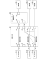
- FIG. 1 is a diagram illustrating an example of the configuration of a communication system according to a first embodiment.
- 4 is a diagram illustrating an example of the configuration of a light distribution unit connection table in the first embodiment.
- FIG. 5A and 5B are diagrams for explaining switching of connection relationships of light distribution units in the first embodiment.
- FIG. 2 is a sequence diagram showing a processing flow of the communication system according to the first embodiment.
- FIG. 11 is a diagram illustrating an example of the configuration of a communication system according to a modified example of the first embodiment.
- 13A and 13B are diagrams for explaining switching of the connection relationship of the light distribution unit in the second embodiment.
- FIG. 13 is a diagram illustrating an example of the configuration of a communication system according to a third embodiment.
- FIG. 13 is a diagram illustrating an example of the configuration of a light distribution unit connection table in the third embodiment.
- FIG. 13 is a diagram illustrating an example of a configuration of an insertion delay table in the third embodiment.
- 13 is a diagram for explaining switching of the connection relationship of the light distribution unit in the third embodiment.
- FIG. FIG. 1 illustrates an example of a conventional communication system. A diagram for explaining an overview of the processing performed by the fronthaul multiplexing device.
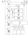
- FIG. 1 is a diagram showing a configuration example of a communication system 100 in the first embodiment.
- the communication system 100 includes one or more antenna stations 10, an optical distribution unit 20, a fronthaul multiplexing device 30, one or more aggregation stations 40, and a controller 50.
- Fig. 1 shows a case where the communication system 100 includes two antenna stations 10-1 to 10-2 and two aggregation stations 40-1 to 40-2, but the number of antenna stations 10 and aggregation stations 40 is not particularly limited.
- antenna stations 10-1 to 10-2 will be referred to as antenna station 10 unless otherwise specified, and aggregation stations 40-1 to 40-2 will be referred to as aggregation station 40 unless otherwise specified.
- the direction from antenna station 10 to aggregation station 40 will be referred to as the uplink direction.
- Optical transmission paths connect the antenna stations 10-1, 10-2 and the optical distribution unit 20, the optical distribution unit 20 and the fronthaul multiplexing device 30, the fronthaul multiplexing device 30 and the aggregation station 40-1, and the optical distribution unit 20 and the aggregation station 40-2.
- the optical transmission path is, for example, an optical fiber, and transmits optical signals.
- the controller 50 and the optical distribution unit 20, and the controller 50 and the aggregation stations 40-1, 40-2 are connected by electrical lines that transmit electrical signals.
- the antenna station 10-1 is accommodated in the aggregation station 40-1 via the optical distribution unit 20 and the fronthaul multiplexing device 30, and the antenna station 10-2 is accommodated in the aggregation station 40-2 via the optical distribution unit 20.
- the fronthaul multiplexing device 30 is accommodated in the aggregation station 40-1.
- the optical distribution unit 20 is an optical distribution device that has a plurality of first ports and a plurality of second ports, and outputs an optical signal input from one port from another port.
- a plurality of antenna stations 10 are connected to the plurality of first ports of the optical distribution unit 20, and a front-haul multiplexing device 30 and an aggregation station 40-2 are connected to the plurality of second ports of the optical distribution unit 20.
- the optical distribution unit 20 switches the connection so that each antenna station 10 is accommodated in the front-haul multiplexing device 30 according to the control of the controller 50.
- the optical distribution unit 20 switches the first port to which the antenna station 10-2 is connected from the second port to which the aggregation station 40-2 is connected to the second port to which the front-haul multiplexing device 30 is connected. In this way, the optical distribution unit 20 accommodates each antenna station 10 in the front-haul multiplexing device 30.
- the optical distribution unit 20 may be an optical switch, a multicast switch, or another switch.
- the fronthaul multiplexing device 30 behaves so that the multiple connected antenna stations 10 appear as a single antenna station 10 when viewed from the aggregation station 40.
- the fronthaul multiplexing device 30 receives uplink signals transmitted from each antenna station 10.
- the fronthaul multiplexing device 30 merges each received uplink signal by performing signal processing on signals that correspond to the same time. In this way, the fronthaul multiplexing device 30 generates a multiplexed signal.
- the fronthaul multiplexing device 30 outputs the generated multiplexed signal to the aggregation station 40-1.
- the aggregation station 40-1 processes the multiplexed signal output from the fronthaul multiplexer 30 or forwards it to a higher level. In this way, the aggregation station 40-1 is connected to a path that passes through the optical distribution unit 20 and the fronthaul multiplexer 30.
- the aggregation station 40-2 processes the upstream signal transferred from the optical distribution unit 20 or transfers it to a higher level. In this way, the aggregation station 40-2 is connected to a route that does not go through the fronthaul multiplexer 30 via the optical distribution unit 20. Furthermore, the aggregation station 40-2 goes into a sleep state in response to an instruction from the controller 50.
- the sleep state is a function that aims to save power by stopping some functions.
- the aggregation stations 40-1 and 40-2 are DUs in the mobile communication system.
- the aggregation station 40 is one aspect of a communication station.
- the controller 50 controls the entire communication system 100.
- the controller 50 acquires, from each of the multiple aggregation stations 40, judgment information used for sleep control of the aggregation stations 40.
- the judgment information is, for example, traffic volume, number of connected terminals, traffic flow, allocation amount, wireless quality information such as CQI (Channel Quality Indicator), priority information such as the communicated 5QI, and information on contracted services.
- CQI Channel Quality Indicator
- priority information such as the communicated 5QI
- information on contracted services information on contracted services.
- the judgment information is traffic volume.
- the controller 50 determines based on the judgment information that the aggregation station 40 to be put to sleep (hereinafter referred to as the "sleep target aggregation station") can be put into a sleep state, it instructs the optical distribution unit 20 to switch.
- the sleep target aggregation station is, for example, an aggregation station 40 (e.g., aggregation station 40-2) that is not connected to a route via the fronthaul multiplexing device 30.
- the controller 50 instructs the sleep target aggregation station to sleep before or after switching the optical distribution unit 20.
- the fronthaul multiplexing device 30 has a lower-order delay insertion unit 31 and a signal merging unit 32.
- the lower-side delay insertion unit 31 receives each upstream signal transferred from the optical distribution unit 20.
- the lower-side delay insertion unit 31 imparts a delay to at least some of the received upstream signals so that the signals are received at the same time.
- imparting a delay means inserting a delay into the signal to delay it.
- the lower-side delay insertion unit 31 imparts a delay to the upstream signal according to the distance difference, for example.
- the signal merging unit 32 multiplexes each upstream signal, including the upstream signal to which a delay has been applied by the lower-order delay insertion unit 31, to generate a multiplexed signal.
- the controller 50 includes an acquisition unit 51, a sleep control unit 52, a sleep detection unit 53, and a switching signal transmission unit 54.
- the acquisition unit 51 acquires the judgment information from each of the multiple aggregation stations 40.
- the acquisition unit 51 acquires the judgment information from each of the multiple aggregation stations 40, for example, at a predetermined timing or periodically.
- the acquisition unit 51 outputs the acquired judgment information of each aggregation station 40 to the sleep control unit 52.
- the sleep control unit 52 judges whether or not the aggregation station 40 can sleep based on the judgment information of each aggregation station 40 acquired by the acquisition unit 51.
- the sleep control unit 52 judges, for example, whether or not the aggregation station to be put to sleep can sleep.
- the sleep control unit 52 judges that the sleep target aggregate station can sleep if the period during which the traffic volume of the sleep target aggregate station remains below the first threshold continues for a predetermined period or more and other aggregate stations 40 can accommodate the traffic of the sleep target aggregate station.
- the sleep control unit 52 determines that the sleep target aggregate station cannot sleep when the traffic volume of the sleep target aggregate station is equal to or greater than the first threshold. Alternatively, the sleep control unit 52 may determine that the sleep target aggregate station cannot sleep when the period during which the traffic volume of the sleep target aggregate station is less than the first threshold does not continue for a predetermined period or more. Alternatively, the sleep control unit 52 may determine that the sleep target aggregate station cannot sleep when other aggregate stations 40 cannot accommodate the traffic of the sleep target aggregate station even if the period during which the traffic volume of the sleep target aggregate station is less than the first threshold continues for a predetermined period or more.
- the sleep control unit 52 judges that the sleep target aggregate station can sleep if the number of connected terminals of the sleep target aggregate station (e.g., the number of antenna stations 10) falls below a predetermined standard and other aggregate stations 40 can accommodate the connected terminals of the sleep target aggregate station.
- the sleep control unit 52 determines that the sleep target aggregate station cannot sleep if the number of connected terminals of the sleep target aggregate station is equal to or greater than a predetermined criterion. Alternatively, the sleep control unit 52 may determine that the sleep target aggregate station cannot sleep if other aggregate stations 40 cannot accommodate the connected terminals of the sleep target aggregate station even if the number of connected terminals of the sleep target aggregate station falls below a predetermined criterion.
- the sleep control unit 52 determines that sleep is possible, it notifies the sleep detection unit 53 that the sleep target aggregation station will be put to sleep. Furthermore, if the sleep control unit 52 determines that sleep is possible, it sends a sleep instruction to the sleep target aggregation station.
- the sleep instruction is an instruction to execute a transition to a sleep state.
- the sleep detection unit 53 detects the transition of the sleep target aggregation station to the sleep state in response to a notification from the sleep control unit 52.
- the sleep detection unit 53 detects the transition to the sleep state of, for example, aggregation station 40-2, which is connected via the optical distribution unit 20 to a route that does not go through the fronthaul multiplexing device 30.
- the switching signal sending unit 54 sends a switching signal including an instruction to switch the accommodation of the antenna station 10 to the optical distribution unit 20.
- the switching signal includes, for example, information indicating the port to which the switching destination aggregation station 40 is connected.
- the switching signal sending unit 54 obtains information to be included in the switching signal, for example, from the optical distribution unit connection table.
- the optical distribution unit connection table is a table in which information regarding the connection of the optical distribution unit 20 is registered. Details of the optical distribution unit connection table will be described later.
- the optical distribution unit connection table is stored in a memory not shown.
- the switching signal sending unit 54 detects that the sleep target aggregate station has transitioned to a sleep state, it sends a switching signal to the optical distribution unit 20 to instruct the switching so that the antenna station 10 accommodated in the sleep target aggregate station is accommodated in the aggregate station 40 that is connected to the path via the optical distribution unit 20 and the fronthaul multiplexing device 30.
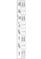
- FIG. 2 is a diagram showing an example of the configuration of the optical distribution unit connection table in the first embodiment.
- the optical distribution unit connection table has a plurality of records in which information related to the connection of the optical distribution unit 20 is registered. Each record has values for lower device, lower device connection port, upper device, upper device connection port, port used during sleep, central station used during sleep, port used during sleep wake-up, and central station compatible during sleep wake-up.
- the lower device represents a lower device connected to the optical distribution unit 20.
- the lower device connected to the optical distribution unit 20 is, for example, the antenna station 10.
- the lower device connection port represents the first port of the optical distribution unit 20 to which the lower device is connected.
- the higher-level device refers to a higher-level device connected to the optical distribution unit 20.
- the higher-level device connected to the optical distribution unit 20 is, for example, the aggregation station 40.
- the higher-level device connection port refers to the second port of the optical distribution unit 20 to which the higher-level device is connected.
- the port used during sleep refers to the second port of the optical distribution unit 20 used as the connection destination of the antenna station 10 when the aggregation station 40 is in sleep mode.
- the aggregation station used during sleep refers to the aggregation station 40 used as the connection destination of the antenna station 10 when the aggregation station 40 is in sleep mode.
- the port used during sleep release refers to the second port of the optical distribution unit 20 used as the connection destination of the antenna station 10 when the aggregation station 40 is released from sleep mode.
- the aggregation station compatible during sleep release refers to the aggregation station 40 used as the connection destination of the antenna station 10 when the aggregation station 40 is released from sleep mode.
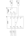
- FIG. 3 is a diagram for explaining switching of the connection relationship of the optical distribution unit 20 in the first embodiment.
- the optical distribution unit 20 has four first ports d1 to d4 and four second ports u1 to u4, and the fronthaul multiplexing device 30 has two first ports p1 to p2 and one second port q1.
- the number of ports provided in the optical distribution unit 20 and the fronthaul multiplexing device 30 is not limited to the example shown in FIG. 3.
- the antenna station 10-1 is connected to the first port d1 of the optical distribution unit 20
- the antenna station 10-2 is connected to the first port d2 of the optical distribution unit 20
- the fronthaul multiplexing device 30 is connected to the second ports u1 and u2 of the optical distribution unit 20
- the aggregation station 40-2 is connected to the second port u3 of the optical distribution unit 20.
- the optical distribution unit 20 is connected to the first ports p1 and p2 of the fronthaul multiplexing device 30, and the aggregation station 40-1 is connected to the second port q1 of the fronthaul multiplexing device 30.
- the first port d1 is connected to the second port u1
- the first port d2 is connected to the second port u3.
- the switching signal transmission unit 54 refers to the optical distribution unit connection table and determines that the aggregation station 40-2 is connected to the second port u3 of the optical distribution unit 20. Furthermore, the switching signal transmission unit 54 determines that the antenna station 10-2 accommodated in the aggregation station 40-2 is connected to the first port d2 of the optical distribution unit 20.
- the switching signal sending unit 54 refers to the items of the port used during sleep and the aggregation station used during sleep in the optical distribution unit connection table, and finds out that when the aggregation station 40-2 goes to sleep, the connection destination of the antenna station 10-2 is the aggregation station 40-1, and that the second port u2 of the optical distribution unit 20 toward the aggregation station 40-1 is used.
- the switching signal sending unit 54 generates a switching signal that instructs switching the connection from the first port d2 of the optical distribution unit 20 to the second port u3 of the optical distribution unit 20 to the connection from the first port d2 of the optical distribution unit 20 to the second port u2 of the optical distribution unit 20.
- the switching signal sending unit 54 sends the generated switching signal to the optical distribution unit 20.
- the optical distribution unit 20 switches the connection so that the first port d2 and the second port u2 are connected, as shown by the dotted line in FIG. 3.
- FIG. 4 is a sequence diagram showing the flow of processing in the communication system 100 in the first embodiment.
- the aggregation stations 40-1 and 40-2 are collectively referred to as an aggregation station group, but will be described as aggregation station 40-1 or 40-2 as necessary.
- the antenna station 10-1 is connected to the aggregation station 40-1 via the optical distribution unit 20 and the fronthaul multiplexer 30, and the antenna station 10-2 is directly connected to the aggregation station 40-2 via the optical distribution unit 20.
- the total traffic volume passing through the aggregation station 40-2 is 10% or more of the amount that the aggregation station 40-2 can process (for example, 1 Gbps).
- the acquisition unit 51 of the controller 50 acquires information on the traffic volume of each aggregation station 40 (step S101). It is assumed that the number of terminal devices connected to the aggregation station 40-2 via the antenna station 10-2 has increased to two before the acquisition unit 51 acquires the traffic volume information of each aggregation station 40. As a result, it is assumed that the average traffic flowing through the aggregation station 40-2 is 5% of the traffic that can be processed by the aggregation stations 40-1 and 40-2, or less than 50 Mbps.
- the acquisition unit 51 outputs the acquired traffic volume information of each aggregation station 40 to the sleep control unit 52.
- the sleep control unit 52 determines whether or not to put the aggregate station 40 to sleep based on the traffic volume information of each aggregate station 40 output from the acquisition unit 51 (step S102). For example, the sleep control unit 52 determines whether or not to put the aggregate station 40-2 to sleep based on the traffic volume information of the aggregate station 40-2. Here, it is assumed that the sleep control unit 52 determines that the aggregate station 40-2 can sleep. In this case, the sleep control unit 52 transmits a sleep instruction to the aggregate station 40-2 (step S203). This allows the aggregate station 40-2 to transition to a sleep state.
- the sleep control unit 52 may transmit a sleep instruction to the aggregation station 40-2 after the optical distribution unit 20 performs the switching.
- the sleep control unit 52 notifies the sleep detection unit 53 that the aggregation station 40-2 will be put to sleep.
- the sleep detection unit 53 detects the transition of the aggregation station 40-2 to the sleep state based on the notification from the sleep control unit 52.
- the sleep detection unit 53 determines that switching is necessary (step S104).
- the sleep detection unit 53 notifies that the connection of the optical distribution unit 20 needs to be switched and that the aggregation station 40-2 will transition to the sleep state.
- the switching signal sending unit 54 generates a switching signal in response to a notification from the sleep detection unit 53. Specifically, the switching signal sending unit 54 refers to the optical distribution unit connection table and generates a switching signal that instructs switching the connection from the first port d2 of the optical distribution unit 20 to the second port u3 of the optical distribution unit 20 to a connection from the first port d2 of the optical distribution unit 20 to the second port u2 of the optical distribution unit 20. The switching signal sending unit 54 transmits the generated switching signal to the optical distribution unit 20 (step S105).
- the optical distribution unit 20 receives the switching signal sent from the controller 50.
- the optical distribution unit 20 switches the connection between the ports based on the received switching signal (step S106). For example, the optical distribution unit 20 switches the connection so that the first port d2 and the second port u2 are connected. By switching the connection, the antenna stations 10-1 and 10-2 are accommodated in the aggregation station 40-1. After that, it is assumed that upstream signals are transmitted from each of the antenna stations 10-1 and 10-2.
- the optical distribution unit 20 inputs the upstream signals transmitted from the antenna stations 10-1 and 10-2 from a first port, and outputs the input upstream signals from a second port.
- the first ports of the optical distribution unit 20 to which the antenna stations 10-1 and 10-2 are connected are connected to a second port to which the fronthaul multiplexing device 30 is connected. As a result, each upstream signal input to the optical distribution unit 20 is forwarded to the fronthaul multiplexing device 30.
- the fronthaul multiplexing device 30 receives each upstream signal transferred from the optical distribution unit 20.
- the distance from the antenna station 10-1 to the fronthaul multiplexing device 30 is often different from the distance from the antenna station 10-2 to the fronthaul multiplexing device 30, and the antenna stations 10-1 and 10-2 also transmit upstream signals at different times. Therefore, the upstream signals transmitted from the antenna stations 10-1 and 10-2 are received at different times by the fronthaul multiplexing device 30.
- the lower-side delay insertion unit 31 of the fronthaul multiplexing device 30 inserts a delay into a portion of each received upstream signal (step S108).
- the delay insertion is the same as in the past.
- the lower-side delay insertion unit 31 outputs each upstream signal, including the upstream signal to which a delay has been applied, to the signal combining unit 32.
- the signal combining unit 32 multiplexes each upstream signal, including the upstream signal to which a delay has been applied by the lower-side delay insertion unit 31, to generate a multiplexed signal (step S109).
- the signal combining unit 32 outputs the generated multiplexed signal to the aggregation station 40-1 (step S110).
- the aggregation station 40-1 receives the multiplexed signal output from the optical distribution unit 20.
- the aggregation station 40-1 then processes the received multiplexed signal or transfers it to a higher level.
- the communication system 100 configured as described above includes a sleep detection unit 53 that detects the transition to a sleep state of the aggregate station 40-2, which is connected to the first route not via the fronthaul multiplexing device 30 via the optical distribution unit 20, among the multiple aggregate stations 40, and a switching signal transmission unit 54 that, when the sleep detection unit 53 detects the transition of the aggregate station 40-2 to the sleep state, transmits a switching signal to the optical distribution unit 20 instructing the optical distribution unit 20 to switch the antenna station 10-2 accommodated in the aggregate station 40-2 that has transitioned to the sleep state to be accommodated in the aggregate station 40 connected to the second route via the optical distribution unit 20 and the fronthaul multiplexing device 30.
- the connection is switched so that the antenna station 10 connected to the aggregation station 40 capable of sleep is accommodated in the aggregation station 40 connected to the fronthaul multiplexer 30.
- delay insertion and signal merging are performed through the fronthaul multiplexer 30, so that the signals of the antenna stations 10-1 and 10-2 are multiplexed and accommodated in one port of the aggregation station 40-1.
- the signal processing of the antenna station 10 can be aggregated in the aggregation station 40 connected to the fronthaul multiplexer 30, which multiplexes the signals of multiple antenna stations 10. This eliminates the need to prepare additional ports or other aggregation stations 40 on the aggregation station 40-1 side. Therefore, the aggregation station 40-2 can be put to sleep, which makes it possible to reduce the power consumption of the entire system compared to switching the aggregation station 40 connected one-to-one to the antenna station 10.
- the switchover is performed when the load on the aggregation station 40 is low enough that it can go to sleep, the impact on users due to bandwidth depletion can be reduced even after aggregation via the fronthaul multiplexing device 30.
- FIG. 5 is a diagram showing a configuration example of a communication system 100a in a modified example of the first embodiment.
- the communication system 100a includes one or more antenna stations 10, an optical distribution unit 20, a fronthaul multiplexing device 30, one or more aggregation stations 40, a wireless controller 60, and an optical distribution unit controller 65.
- FIG. 5 shows a case in which the communication system 100a includes two antenna stations 10-1 to 10-2 and two aggregation stations 40-1 to 40-2, but the number of antenna stations 10 and aggregation stations 40 is not particularly limited.
- the communication system 100a differs from the communication system 100 in that it includes a wireless controller 60 and an optical distribution unit controller 65 instead of the controller 50.
- the rest of the configuration of the communication system 100a is the same as that of the communication system 100. The following mainly describes the differences.
- the wireless controller 60 communicates wirelessly with the aggregation station 40 and with the optical distribution unit controller 65.
- the wireless controller 60 includes an acquisition unit 51 and a sleep control unit 52.
- the acquisition unit 51 included in the wireless controller 60 wirelessly acquires the judgment information from each of the multiple aggregate stations 40.
- the acquisition unit 51 wirelessly acquires the judgment information from each of the multiple aggregate stations 40, for example, at a predetermined timing or periodically.
- the acquisition unit 51 outputs the acquired judgment information of each aggregate station 40 to the sleep control unit 52.
- the sleep control unit 52 included in the wireless controller 60 judges whether the aggregate station 40 can sleep based on the judgment information of each aggregate station 40 acquired by the acquisition unit 51.
- the sleep control unit 52 determines that sleep is possible, it notifies the optical distribution unit controller 65 by radio that the sleep target aggregation station is to be put to sleep. Furthermore, if the sleep control unit 52 determines that sleep is possible, it transmits a sleep instruction by radio to the sleep target aggregation station.
- the optical distribution unit controller 65 controls the optical distribution unit 20.
- the optical distribution unit controller 65 includes a sleep detection unit 53 and a switching signal transmission unit 54.
- the sleep detection unit 53 included in the optical distribution unit controller 65 detects the transition of the sleep target aggregation station to a sleep state in response to a notification from the wireless controller 60.
- the switching signal transmission unit 54 included in the optical distribution unit controller 65 transmits a switching signal to the optical distribution unit 20 when the sleep detection unit 53 detects the transition of the sleep target aggregation station to a sleep state.
- the switching operation of the optical distribution unit 20 by the switching signal transmission unit 54 is the same as the method shown in the first embodiment.
- Second Embodiment a configuration in the case where a sleeping aggregate station is released from sleep will be described.
- the system configuration and device configuration in the second embodiment are similar to those in the first embodiment.
- the difference from the first embodiment is the operation of the controller 50.
- the sleep control unit 52 determines whether or not it is necessary to wake up the sleeping aggregate station 40 based on the determination information of each aggregate station 40 acquired by the acquisition unit 51.
- the aggregate station 40 that is the target for sleep wakeup is referred to as the sleep wakeup target aggregate station.
- the sleep control unit 52 determines that the sleep release target aggregate station needs to be released when the traffic volume of the aggregate station 40 that is not in the sleep state is equal to or greater than the second threshold value. On the other hand, when the traffic volume of the aggregate station 40 that is not in the sleep state is less than the second threshold value, the sleep control unit 52 determines that the sleep release target aggregate station does not need to be released.
- the sleep control unit 52 judges that it is necessary to wake up the target aggregate station for sleep release when the number of connected terminals (e.g., the number of antenna stations 10) of the aggregate station 40 that is not in a sleep state is equal to or greater than a predetermined criterion. On the other hand, when the number of connected terminals of the aggregate station 40 that is not in a sleep state is less than the predetermined criterion, the sleep control unit 52 judges that it is not necessary to wake up the target aggregate station for sleep release.
- the number of connected terminals e.g., the number of antenna stations
- the sleep control unit 52 determines that a sleep wakeup is necessary, it notifies the sleep detection unit 53 that it will start waking up the aggregation station to be woken up. Furthermore, when the sleep control unit 52 determines that a sleep wakeup is necessary, it transmits a sleep wakeup instruction to the aggregation station to be woken up.
- the sleep wakeup instruction is an instruction to wake up the sleep state.
- the sleep detection unit 53 detects the start of sleep wakeup of the target aggregation station in response to a notification from the sleep control unit 52. For example, the sleep detection unit 53 detects the start of sleep wakeup of the aggregation station 40-2 that is connected via a route that does not go through the fronthaul multiplexing device 30 via the optical distribution unit 20.
- the switching signal sending unit 54 sends a switching signal including an instruction to switch the accommodation of the antenna station 10 to the optical distribution unit 20.
- the switching signal sending unit 54 obtains information to be included in the switching signal, for example, from the optical distribution unit connection table.
- the switching signal sending unit 54 detects the start of sleep wakeup of the target aggregation station to be woken up, it sends a switching signal to the optical distribution unit 20 to instruct the switching so that the antenna station 10 accommodated in the aggregation station 40 that is not asleep is accommodated in the aggregation station 40 that is connected via the optical distribution unit 20 to a route that does not go through the fronthaul multiplexing device 30.
- FIG. 6 is a diagram for explaining the switching of the connection relationship of the light distribution unit 20 in the second embodiment. What differs from FIG. 3 in that inside the light distribution unit 20, the first port d1 is connected to the second port u1, and the first port d2 is connected to the second port u2.
- the switching signal sending unit 54 refers to the optical distribution unit connection table and determines that the aggregation station 40-2 is connected to the second port u3 of the optical distribution unit 20. Furthermore, the switching signal sending unit 54 determines that the antenna station 10-2 is connected to the first port d2 of the optical distribution unit 20.
- the switching signal sending unit 54 refers to the items of the port used at sleep release and the corresponding central station at sleep release in the optical distribution unit connection table, and finds out that when the central station 40-2 wakes up from sleep, the connection destination of the antenna station 10-2 is the central station 40-2, and that the second port u3 of the optical distribution unit 20 toward the central station 40-2 is to be used. As a result, the switching signal sending unit 54 generates a switching signal that instructs switching the connection from the first port d2 of the optical distribution unit 20 to the second port u2 of the optical distribution unit 20 to the connection from the first port d2 of the optical distribution unit 20 to the second port u3 of the optical distribution unit 20. The switching signal sending unit 54 sends the generated switching signal to the optical distribution unit 20. As a result, the optical distribution unit 20 switches the connection so that the first port d2 and the second port u3 are connected, as shown by the dotted line in FIG. 6.
- the antenna station 10-2 is reconnected to the aggregation station 40-2, and is then able to use the frequency resources of the aggregation station 40-2 that are not shared with the aggregation station 40-1. Therefore, even if the number of accommodated terminals increases, or terminals with high communication volumes or terminals requiring low latency are accommodated, service requests can be satisfied.
- the controller 50 judges whether or not sleep is to be cancelled and issues a switching command to the optical distribution unit 20.
- the judgement of whether or not sleep is to be cancelled and the switching command to the optical distribution unit 20 may be performed by different devices.
- the communication system 100 in the second embodiment includes a wireless controller 60 and an optical distribution unit controller 65 instead of the controller 50, similar to the modified example of the first embodiment.
- the wireless controller 60 wirelessly communicates with the aggregation station 40 and with the optical distribution unit controller 65.
- the wireless controller 60 includes an acquisition unit 51 and a sleep control unit 52.
- the acquisition unit 51 included in the wireless controller 60 wirelessly acquires the judgment information from each of the multiple aggregation stations 40.
- the acquisition unit 51 wirelessly acquires the judgment information from each of the multiple aggregation stations 40, for example, at a predetermined timing or periodically.
- the acquisition unit 51 outputs the acquired judgment information of each aggregation station 40 to the sleep control unit 52.
- the sleep control unit 52 included in the wireless controller 60 judges whether or not the sleep of the aggregation station to be released from sleep is required based on the judgment information of each aggregation station 40 acquired by the acquisition unit 51. If the sleep control unit 52 judges that a sleep release is required, it notifies the optical distribution unit controller 65 wirelessly to start releasing the sleep of the aggregation station to be released from sleep. Furthermore, if the sleep control unit 52 judges that a sleep release is required, it wirelessly transmits a sleep release instruction to the aggregation station to be released from sleep.
- the optical distribution unit controller 65 controls the optical distribution unit 20.
- the optical distribution unit controller 65 includes a sleep detection unit 53 and a switching signal transmission unit 54.
- the sleep detection unit 53 included in the optical distribution unit controller 65 detects the start of sleep wakeup of the aggregation station to be woken up in response to a notification from the wireless controller 60.
- the switching signal transmission unit 54 included in the optical distribution unit controller 65 transmits a switching signal to the optical distribution unit 20 when the sleep detection unit 53 detects the start of sleep wakeup of the aggregation station to be woken up.
- the switching operation of the optical distribution unit 20 by the switching signal transmission unit 54 is the same as the method shown in the second embodiment.
- FIG. 7 is a diagram showing an example of the configuration of a communication system 100b in the third embodiment.
- the communication system 100b includes one or more antenna stations 10, an optical distribution unit 20, a fronthaul multiplexing device 30b, one or more aggregation stations 40, and a controller 50b.
- FIG. 7 shows a case in which the communication system 100b includes three antenna stations 10-1 to 10-3 and two aggregation stations 40-1 to 40-2, but the number of antenna stations 10 and aggregation stations 40 is not particularly limited.
- Optical transmission paths connect the antenna stations 10-1, 10-2, 10-3 and the optical distribution unit 20, the optical distribution unit 20 and the fronthaul multiplexing device 30b, the fronthaul multiplexing device 30b and the aggregation station 40-1, and the optical distribution unit 20 and the aggregation stations 40-2, 40-3.
- Electric lines that transmit electrical signals connect the controller 50b and the optical distribution unit 20, the controller 50b and the fronthaul multiplexing device 30b, and the controller 50b and the aggregation stations 40-1, 40-2.
- the antenna station 10-1 is accommodated in the aggregation station 40-1 via the optical distribution unit 20 and the fronthaul multiplexing device 30b, and the antenna stations 10-2 and 10-3 are accommodated in the aggregation stations 40-2 and 40-3 via the optical distribution unit 20.
- the fronthaul multiplexing device 30b is accommodated in the aggregation station 40-1.
- Communication system 100b differs from communication system 100 in that it has a fronthaul multiplexing device 30b and a controller 50b instead of the fronthaul multiplexing device 30 and the controller 50, and in that it has three antenna stations 10 and three aggregation stations 40.
- the rest of the configuration of communication system 100b is the same as that of communication system 100. The following will focus on the differences.
- the controller 50b controls the entire communication system 100b.
- the controller 50b acquires judgment information used for sleep control of the aggregation station 40 from each of the multiple aggregation stations 40. Furthermore, the controller 50b acquires in advance the delay time (hereinafter referred to as "lower delay time") from the antenna station 10 to which the connection destination is switched to the fronthaul multiplexing device 30b in response to the switching of the connection relationship by the optical distribution unit 20.
- the antenna station 10 to which the new connection destination is connected to the aggregation station 40 via the optical distribution unit 20 and the fronthaul multiplexing device 30 is the target for acquiring the lower delay time by the controller 50b.
- the antenna station 10 for example, the antenna station 10-1 that connects to the aggregation station 40 via the optical distribution unit 20 and the fronthaul multiplexing device 30 before the connection switching by the optical distribution unit 20, communication is being performed between the antenna station 10-1 and the aggregation station 40-1, and therefore the lower delay time between the antenna station 10-1 and the fronthaul multiplexing device 30b is measured.
- the antenna stations 10-2 and 10-3 are connected to the aggregation station 40, which is connected via the optical distribution unit 20 to a route that does not go through the fronthaul multiplexing device 30. Therefore, the lower-level delay times between the antenna stations 10-2 and 10-3 and the fronthaul multiplexing device 30b are not measured. Therefore, the antenna stations 10-2 and 10-3 are targets from which the controller 50b acquires the lower-level delay times. The controller 50b notifies the fronthaul multiplexing device 30b of the acquired lower-level delay time information. As a result, the fronthaul multiplexing device 30b reuses the value of the lower-level delay time notified by the controller 50b, and does not need to remeasure the delay time between the newly connected antenna station 10.
- the fronthaul multiplexing device 30b behaves so that the multiple connected antenna stations 10 appear as a single antenna station 10 when viewed from the aggregation station 40.
- the fronthaul multiplexing device 30b receives uplink signals transmitted from each antenna station 10.
- the fronthaul multiplexing device 30b merges each received uplink signal by performing signal processing on signals that correspond to the same time. In this way, the fronthaul multiplexing device 30b generates a multiplexed signal.
- the fronthaul multiplexing device 30b outputs the generated multiplexed signal to the aggregation station 40-1.
- the fronthaul multiplexing device 30b When applying a delay to each upstream signal, the fronthaul multiplexing device 30b obtains information on the lower-order delay time from the controller 50b in advance. The fronthaul multiplexing device 30b then obtains the delay time to be applied to the upstream signal transmitted from each antenna station 10 based on the obtained information on the lower-order delay time. As described above, the lower-order delay time is the delay time between the antenna station 10 and the fronthaul multiplexing device 30b.
- the fronthaul multiplexing device 30b adds or selects signals that correspond to the same time, so it obtains the delay time to be applied to each upstream signal for each upstream signal, taking the lower-order delay time into account, so that the upstream signals have the same delay. The fronthaul multiplexing device 30b can then merge each upstream signal by applying the obtained delay time to each upstream signal.
- the fronthaul multiplexing device 30b has a lower-order delay insertion unit 31b, a signal merging unit 32, and a switching notification receiving unit 33.
- the switching notification receiver 33 receives information on the lower delay time corresponding to the antenna station 10 (hereinafter referred to as the "antenna station to be switched") newly connected to the fronthaul multiplexing device 30b from the controller 50b. Based on the received information on the lower delay time and the insertion delay table, the switching notification receiver 33 acquires the delay time to be added to the upstream signal transmitted from each antenna station 10 connected to the fronthaul multiplexing device 30b.
- the delay time to be added to the upstream signal will be referred to as the insertion delay time.
- the insertion delay table is a table in which information on the insertion delay time is registered. Details of the insertion delay table will be described later.
- the insertion delay table is stored in a memory (not shown).
- the switching notification receiver 33 notifies the lower side delay insertion unit 31b of the acquired information on the insertion delay time of each antenna station 10.
- the lower-side delay insertion unit 31b receives each upstream signal transferred from the optical distribution unit 20.
- the lower-side delay insertion unit 31b imparts a delay value indicated by the delay time information notified by the switching notification receiving unit 33 to at least some of the received upstream signals. This allows the lower-side delay insertion unit 31b to treat each upstream signal transmitted from a different antenna station 10 as a signal received at the same time.
- the controller 50b includes an acquisition unit 51, a sleep control unit 52, a sleep detection unit 53, a switching signal transmission unit 54, and a delay time management unit 55.
- the delay time management unit 55 acquires information on the lower-level delay time corresponding to the antenna station to be switched to.
- the delay time management unit 55 may calculate the lower-level delay time from a measurement value using AMCC (Auxiliary Management and Control Channel), or may hold a value previously measured by the fronthaul multiplexer 30b.
- AMCC Advanced Management and Control Channel
- the delay time management unit 55 sends a delay measurement signal to the antenna station to be switched to, measures the propagation delay between the optical distribution unit 20 and the antenna station to be switched to, and holds a value obtained by halving the round-trip delay time as the one-way delay.
- the delay time management unit 55 notifies the switching notification receiving unit 33 of the fronthaul multiplexing device 30 that the switching target antenna station will be connected and provides information on the delay time corresponding to the connected switching target antenna station.
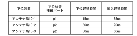
- FIG. 9 is a diagram showing an example of the configuration of an insertion delay table in the third embodiment.
- the insertion delay table has multiple records in which information related to the insertion delay time is registered. Each record has a lower device, a lower device connection port, a lower delay time, and an insertion delay time value.
- the lower device in the insertion delay table represents the lower device connected to the fronthaul multiplexing device 30b.
- the lower device connected to the fronthaul multiplexing device 30b is, for example, the antenna station 10.
- the lower device connection port represents the first port of the fronthaul multiplexing device 30b to which the lower device is connected.
- the lower delay time represents the delay time required for transmission between the antenna station 10 and the fronthaul multiplexing device 30b.
- the insertion delay time represents the delay time added to the upstream signal.
- the lower delay times from the antenna stations 10-1, 10-2, and 10-3 to the fronthaul multiplexing device 30b are 15 us, 30 us, and 50 us, respectively.
- the delay time management unit 55 obtains the insertion delay time based on the lower delay time so that the sum of the lower delay time and the insertion delay time is the same value (so that the delay is the same) for each of the antenna stations 10-1, 10-2, and 10-3.
- FIG. 9 shows an example in which the insertion delay time is obtained so that the total value is 100 us.
- FIG. 10 is a diagram for explaining switching of the connection relationship of the optical distribution unit 20 in the third embodiment.
- the optical distribution unit 20 has four first ports d1 to d4 and four second ports u1 to u4, and the fronthaul multiplexing device 30b has two first ports p1 to p2 and one second port q1.
- the number of ports provided in the optical distribution unit 20 and the fronthaul multiplexing device 30b is not limited to the example shown in FIG. 10.
- an antenna station 10-1 is connected to the first port d1 of the optical distribution unit 20
- an antenna station 10-2 is connected to the first port d3 of the optical distribution unit 20
- an antenna station 10-4 is connected to the first port d4 of the optical distribution unit 20.
- a fronthaul multiplexer 30b is connected to the second ports u1 and u2 of the optical distribution unit 20
- an aggregation station 40-2 is connected to the second port u3 of the optical distribution unit 20
- an aggregation station 40-3 is connected to the second port u4 of the optical distribution unit 20.
- the optical distribution unit 20 is connected to the first ports p1 and p2 of the fronthaul multiplexing device 30b, and the aggregation station 40-1 is connected to the second port q1 of the fronthaul multiplexing device 30b.
- the first port d1 is connected to the second port u1
- the first port d3 is connected to the second port u3
- the first port d4 is connected to the second port u4.
- the delay time management unit 55 refers to the insertion delay table and determines whether or not information on the lower-level delay time between the antenna station 10-3 accommodated in the aggregation station 40-3 and the fronthaul multiplexing device 30b is registered.
- the delay time management unit 55 obtains the insertion delay time using the registered information on the lower-level delay time.
- the delay time management unit 55 obtains an insertion delay time based on the lower-level delay time between the antenna station 10-1 and the fronthaul multiplexing device 30b and the lower-level delay time between the antenna station 10-3 accommodated in the aggregation station 40-3 and the fronthaul multiplexing device 30b, so that the delay is the same.
- the switching notification receiver 33 of the fronthaul multiplexer 30b identifies the antenna station 10 that will be connected based on the information sent from the controller 50b. Furthermore, the switching notification receiver 33 sets the insertion delay time information corresponding to each antenna obtained from the controller 50b in the lower delay insertion unit 31 at the timing when the optical distribution unit 20 is switched. For example, the switching notification receiver 33 sets the upstream signal transmitted from the antenna station 10-1 to be delayed by 85 us, and the upstream signal transmitted from the antenna station 10-3 to be delayed by 50 us.
- the switching signal transmission unit 54 refers to the optical distribution unit connection table and determines that the aggregation station 40-3 is connected to the second port u4 of the optical distribution unit 20. Furthermore, the switching signal transmission unit 54 determines that the antenna station 10-3 accommodated in the aggregation station 40-3 is connected to the first port d4 of the optical distribution unit 20.
- the switching signal sending unit 54 refers to the items of the port used during sleep and the aggregation station used during sleep in the optical distribution unit connection table, and finds out that when the aggregation station 40-3 goes to sleep, the connection destination of the antenna station 10-3 is the aggregation station 40-1, and that the second port u2 of the optical distribution unit 20 toward the aggregation station 40-1 is used.
- the switching signal sending unit 54 generates a switching signal that instructs switching the connection from the first port d4 of the optical distribution unit 20 to the second port u4 of the optical distribution unit 20 to the connection from the first port d4 of the optical distribution unit 20 to the second port u2 of the optical distribution unit 20.
- the switching signal sending unit 54 sends the generated switching signal to the optical distribution unit 20.
- the optical distribution unit 20 switches the connection so that the first port d4 and the second port u2 are connected, as shown by the dotted line in FIG. 10.
- the switching notification receiver 33 of the fronthaul multiplexer 30b sets the lower delay insertion unit 31 to impart a delay of 85 us to the upstream signal transmitted from the antenna station 10-1, and sets the lower delay insertion unit 31 to impart a delay of 50 us to the upstream signal transmitted from the antenna station 10-3.
- the upstream signals transmitted from the antenna stations 10-1 and 10-3 are imparted with the above delay in the fronthaul multiplexer 30b.
- the time is adjusted, and a multiplexed signal is generated in the signal combining unit 32.
- the fronthaul multiplexing device measures the propagation delay time between the newly connected antenna station and the new antenna station, and inserts a delay in the lower delay insertion unit so that the new antenna station is synchronized with the timing at which the uplink signal from the other antenna station is sent to the aggregation station.
- the fronthaul multiplexing device 30b acquires the delay time (insertion delay time) to be applied to the uplink signal of the newly connected antenna station 10 in the lower delay insertion unit 31 based on the information on the lower delay time received from the switching signal transmission unit 54.
- the fronthaul multiplexing device 30b can determine an appropriate insertion delay time without measuring the delay, and can apply the delay in the lower delay insertion unit 31. Therefore, the switching can be completed in a shorter time. As a result, the occurrence of packet loss can be suppressed or prevented.
- the controller 50b determines whether or not to sleep and issues a switching command to the optical distribution unit 20.
- the determination of whether or not to sleep and the switching command to the optical distribution unit 20 may be performed by different devices.
- the communication system 100b in the third embodiment includes a wireless controller 60 and an optical distribution unit controller 65 instead of the controller 50b, similar to the modified example of the first embodiment.
- the wireless controller 60 wirelessly communicates with the aggregation station 40 and with the optical distribution unit controller 65.
- the wireless controller 60 includes an acquisition unit 51 and a sleep control unit 52.
- the acquisition unit 51 included in the wireless controller 60 wirelessly acquires the judgment information from each of the multiple aggregate stations 40.
- the acquisition unit 51 wirelessly acquires the judgment information from each of the multiple aggregate stations 40, for example, at a predetermined timing or periodically.
- the acquisition unit 51 outputs the acquired judgment information of each aggregate station 40 to the sleep control unit 52.
- the sleep control unit 52 included in the wireless controller 60 judges whether the aggregate station 40 can sleep based on the judgment information of each aggregate station 40 acquired by the acquisition unit 51.
- the sleep control unit 52 determines that sleep is possible, it notifies the optical distribution unit controller 65 by radio that the sleep target aggregation station is to be put to sleep. Furthermore, if the sleep control unit 52 determines that sleep is possible, it transmits a sleep instruction by radio to the sleep target aggregation station.
- the optical distribution unit controller 65 controls the optical distribution unit 20.
- the optical distribution unit controller 65 includes a sleep detection unit 53, a switching signal transmission unit 54, and a delay time management unit 55.
- the sleep detection unit 53 included in the optical distribution unit controller 65 detects the transition of the sleep target aggregation station to a sleep state in response to a notification from the wireless controller 60.
- the switching signal transmission unit 54 included in the optical distribution unit controller 65 transmits a switching signal to the optical distribution unit 20 when the sleep detection unit 53 detects the transition of the sleep target aggregation station to a sleep state.
- the switching operation of the optical distribution unit 20 by the switching signal transmission unit 54 is the same as the method shown in the third embodiment.
- the delay time management unit 55 included in the optical distribution unit controller 65 acquires information on the lower delay time corresponding to the switching target antenna station when the sleep detection unit 53 detects that the sleep target aggregate station has transitioned to a sleep state.
- the processing performed by the delay time management unit 55 is the same as in the third embodiment.
- the communication system 100b may be configured to wake up a sleeping aggregate station, similarly to the second embodiment. Furthermore, when the communication system 100b is configured to wake up a sleeping aggregate station, it may be configured to have a different device determine whether or not to wake up the aggregate station and issue a switching instruction to the optical distribution unit 20, similarly to the modified example of the second embodiment.
- the aggregation station 40 may be a virtualized aggregation station 40. This makes it possible to use an information processing device having a virtualization function, and the above processing can be realized without a dedicated device.
- At least some or all of the functional units of the fronthaul multiplexing device 30, 30b and the controllers 50, 50b are realized as software by a processor such as a CPU (Central Processing Unit) executing a program stored in a storage device having a non-volatile recording medium (non-transient recording medium) and in the storage unit.
- the program may be recorded on a computer-readable non-transient recording medium.
- Examples of computer-readable non-transient recording media include portable media such as flexible disks, optical magnetic disks, ROMs (Read Only Memory), and CD-ROMs (Compact Disc Read Only Memory), and storage devices such as hard disks built into a computer system.
- At least some or all of the functional units of the fronthaul multiplexing devices 30, 30b, or some or all of the functional units of the controllers 50, 50b may be realized using hardware including electronic circuits (electronic circuits or circuitry) using, for example, an LSI (Large Scale Integrated circuit), an ASIC (Application Specific Integrated Circuit), a PLD (Programmable Logic Device), or an FPGA (Field Programmable Gate Array).
- the present invention can be applied to communication systems equipped with fronthaul multiplexing devices.
Landscapes
- Engineering & Computer Science (AREA)
- Computer Networks & Wireless Communication (AREA)
- Signal Processing (AREA)
- Mobile Radio Communication Systems (AREA)
Abstract
Ce dispositif de commande comprend : une unité de détection de sommeil qui détecte une transition, vers un état de sommeil, d'une station de communication connectée à un premier trajet parmi une pluralité de stations de communication recevant une ou plusieurs stations de réception de terminaux qui communiquent avec des terminaux, le premier trajet contournant un multiplexeur fronthaul qui multiplexe des signaux émis par la ou les stations de réception de terminaux et délivre le signal multiplexé par l'intermédiaire d'une unité de distribution optique qui délivre des signaux, délivrés par la ou les stations de réception de terminaux, à d'autres trajets; et une unité de transmission de signaux de commutation qui transmet un signal de commutation à l'unité de distribution optique lorsque la transition de la station de communication à l'état de sommeil est détectée par l'unité de détection de sommeil, le signal de commutation ordonnant que la station de réception de terminaux logée dans la station de communication qui a passé à l'état de sommeil soit reçue dans la station de communication connectée à un second trajet qui passe à travers l'unité de distribution optique et le multiplexeur fronthaul.
Priority Applications (2)
| Application Number | Priority Date | Filing Date | Title |
|---|---|---|---|
| JP2025525532A JPWO2024252566A1 (fr) | 2023-06-07 | 2023-06-07 | |
| PCT/JP2023/021182 WO2024252566A1 (fr) | 2023-06-07 | 2023-06-07 | Dispositif de commande, multiplexeur fronthaul, procédé de commutation de connexion et multiplexeur |
Applications Claiming Priority (1)
| Application Number | Priority Date | Filing Date | Title |
|---|---|---|---|
| PCT/JP2023/021182 WO2024252566A1 (fr) | 2023-06-07 | 2023-06-07 | Dispositif de commande, multiplexeur fronthaul, procédé de commutation de connexion et multiplexeur |
Publications (1)
| Publication Number | Publication Date |
|---|---|
| WO2024252566A1 true WO2024252566A1 (fr) | 2024-12-12 |
Family
ID=93795455
Family Applications (1)
| Application Number | Title | Priority Date | Filing Date |
|---|---|---|---|
| PCT/JP2023/021182 Ceased WO2024252566A1 (fr) | 2023-06-07 | 2023-06-07 | Dispositif de commande, multiplexeur fronthaul, procédé de commutation de connexion et multiplexeur |
Country Status (2)
| Country | Link |
|---|---|
| JP (1) | JPWO2024252566A1 (fr) |
| WO (1) | WO2024252566A1 (fr) |
Citations (3)
| Publication number | Priority date | Publication date | Assignee | Title |
|---|---|---|---|---|
| JP2019029842A (ja) * | 2017-07-31 | 2019-02-21 | 株式会社Nttドコモ | フロントホールマルチプレクサおよび無線通信システム |
| WO2020095460A1 (fr) * | 2018-11-09 | 2020-05-14 | 株式会社Nttドコモ | Dispositif de traitement de signal, dispositif radio, multiplexeur de transmission frontale, procédé de commande de faisceau et procédé de combinaison de signal |
| JP2023013944A (ja) * | 2021-07-16 | 2023-01-26 | ソリッド インコーポレイテッド | フロントホール多重化装置 |
-
2023
- 2023-06-07 JP JP2025525532A patent/JPWO2024252566A1/ja active Pending
- 2023-06-07 WO PCT/JP2023/021182 patent/WO2024252566A1/fr not_active Ceased
Patent Citations (3)
| Publication number | Priority date | Publication date | Assignee | Title |
|---|---|---|---|---|
| JP2019029842A (ja) * | 2017-07-31 | 2019-02-21 | 株式会社Nttドコモ | フロントホールマルチプレクサおよび無線通信システム |
| WO2020095460A1 (fr) * | 2018-11-09 | 2020-05-14 | 株式会社Nttドコモ | Dispositif de traitement de signal, dispositif radio, multiplexeur de transmission frontale, procédé de commande de faisceau et procédé de combinaison de signal |
| JP2023013944A (ja) * | 2021-07-16 | 2023-01-26 | ソリッド インコーポレイテッド | フロントホール多重化装置 |
Also Published As
| Publication number | Publication date |
|---|---|
| JPWO2024252566A1 (fr) | 2024-12-12 |
Similar Documents
| Publication | Publication Date | Title |
|---|---|---|
| US8565827B2 (en) | Method and apparatus for power saving in wireless communication node B | |
| CN101771591B (zh) | 一种rru与bbu环形组网下的业务传输方法及系统 | |
| US11622324B2 (en) | Network node power control | |
| US20120094706A1 (en) | Wireless communication system, wireless communication method, terminal apparatus, and communication apparatus | |
| US20200252875A1 (en) | Power consumption control method and apparatus | |
| US10057847B2 (en) | QOS-based cooperative scheduling for handling of data traffic | |
| EP2417802A1 (fr) | Programmation de communication de données | |
| CN109756989A (zh) | 数据传输的方法、用户设备及基站 | |
| WO2011094962A1 (fr) | Procédé et dispositif terminal sans fil pour réduire la puissance consommée du dispositif terminal sans fil | |
| JP2015500601A (ja) | プロセッサのパフォーマンスレベルを管理するための無線広域ネットワークプロトコル情報の使用 | |
| CN103200655A (zh) | 一种射频拉远系统的节能方法及装置 | |
| US20240370075A1 (en) | Methodology for vran power savings based on projected computation load | |
| CN102355714A (zh) | 基站及其节能方法、控制设备和系统 | |
| US20100248613A1 (en) | Wireless Communication Device and Transmission Method | |
| ES2610785T3 (es) | Método para reducir el consumo de energía en el terminal inalámbrico y terminal inalámbrico | |
| US20120155381A1 (en) | Method and apparatus for using a wireless device with multiple radios | |
| EP3657851B1 (fr) | Procédé et appareil de régulation de consommation d'énergie | |
| US20120060043A1 (en) | Apparatus and method for controlling power in a wireless communication system | |
| US20250024524A1 (en) | Automatic isochronous adaption layer mode switching | |
| CN1988706A (zh) | 多模通信系统及在多模通信系统内传输信息的方法 | |
| US7764601B2 (en) | Switching between layer 2 switches as destination of IP packets from cards | |
| WO2024252563A1 (fr) | Dispositif de commande, multiplexeur fronthaul, procédé de commutation de connexion et procédé de multiplexage | |
| CN112020099B (zh) | 一种上行数据的分流方法及装置 | |
| US11457421B2 (en) | Auxiliary bluetooth circuit of multi-member bluetooth device capable of reducing complexity of updating internal clock of bluetooth circuit | |
| WO2016054782A1 (fr) | Procédé, dispositif et système d'économie d'énergie sur réseau optique passif |
Legal Events
| Date | Code | Title | Description |
|---|---|---|---|
| 121 | Ep: the epo has been informed by wipo that ep was designated in this application |
Ref document number: 23940668 Country of ref document: EP Kind code of ref document: A1 |
|
| ENP | Entry into the national phase |
Ref document number: 2025525532 Country of ref document: JP Kind code of ref document: A |
|
| NENP | Non-entry into the national phase |
Ref country code: DE |
|
| 122 | Ep: pct application non-entry in european phase |
Ref document number: 23940668 Country of ref document: EP Kind code of ref document: A1 |