WO2024252572A1 - Abnormality determination device - Google Patents
Abnormality determination device Download PDFInfo
- Publication number
- WO2024252572A1 WO2024252572A1 PCT/JP2023/021202 JP2023021202W WO2024252572A1 WO 2024252572 A1 WO2024252572 A1 WO 2024252572A1 JP 2023021202 W JP2023021202 W JP 2023021202W WO 2024252572 A1 WO2024252572 A1 WO 2024252572A1
- Authority
- WO
- WIPO (PCT)
- Prior art keywords
- relay
- microcomputer
- abnormal state
- state
- abnormality
- Prior art date
- Legal status (The legal status is an assumption and is not a legal conclusion. Google has not performed a legal analysis and makes no representation as to the accuracy of the status listed.)
- Ceased
Links
Images
Classifications
-
- B—PERFORMING OPERATIONS; TRANSPORTING
- B60—VEHICLES IN GENERAL
- B60R—VEHICLES, VEHICLE FITTINGS, OR VEHICLE PARTS, NOT OTHERWISE PROVIDED FOR
- B60R16/00—Electric or fluid circuits specially adapted for vehicles and not otherwise provided for; Arrangement of elements of electric or fluid circuits specially adapted for vehicles and not otherwise provided for
- B60R16/02—Electric or fluid circuits specially adapted for vehicles and not otherwise provided for; Arrangement of elements of electric or fluid circuits specially adapted for vehicles and not otherwise provided for electric constitutive elements
Definitions
- This disclosure relates to an abnormality determination device.
- Patent Document 1 discloses an electronic control device for a vehicle that includes a microcomputer. Each time the start switch is turned off, the microcomputer compares the charge state of the vehicle battery with the power consumption required to start up the vehicle equipment. If the battery charge state is at an acceptable level, the microcomputer starts a timer measuring the amount of time the vehicle has been left unattended. In the vehicle electronic control device, the microcomputer starts up the vehicle equipment when a predetermined amount of time has elapsed since the timer indicates that the vehicle has been left unattended. After the start switch is turned off, the microcomputer uses the vehicle equipment to diagnose various abnormalities when the predetermined amount of time has elapsed since the vehicle was left unattended.
- the timing for abnormality diagnosis is limited to when the vehicle has been left unattended for a certain period of time.
- One possible method for detecting abnormalities early is, for example, to start up the microcomputer and on-board equipment at predetermined intervals and have abnormality diagnosis performed at each predetermined interval.
- the more quickly an abnormality is to be detected the shorter the predetermined period must be, which poses the problem of increased power consumption by the microcomputer.
- the purpose of this disclosure is to provide technology that enables efficient anomaly detection by a microcomputer while reducing power consumption when the vehicle is parked.
- the abnormality determination device of the present disclosure is An abnormality determination device mounted on a vehicle, an abnormality detection unit provided in the vehicle that detects that the determination target is in a first abnormal state and outputs a detection signal; a microcomputer that performs a determination process to determine whether the determination target is in a second abnormal state in a startup state, The microcomputer goes into a sleep state when the vehicle is parked, and switches to the wake-up state when the detection signal is input in the sleep state to perform the determination process.
- the technology disclosed herein can efficiently detect abnormalities using a microcomputer while reducing power consumption when the vehicle is parked.
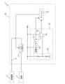
- FIG. 1 is a schematic diagram of a vehicle including an abnormality determination device according to a first embodiment.
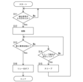
- FIG. 2 is a flowchart showing a flow of processing performed by the microcomputer of the first embodiment.
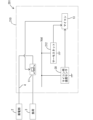
- FIG. 3 is a schematic diagram showing the configuration of a vehicle including an abnormality determination device according to the second embodiment.
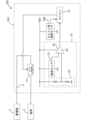
- FIG. 4 is a schematic diagram showing the configuration of a vehicle including an abnormality determination device according to the third embodiment.
- FIG. 5 is a schematic diagram showing the configuration of a vehicle including an abnormality determination device according to the fourth embodiment.
- FIG. 6 is a schematic diagram showing the configuration of a vehicle including an abnormality determination device according to the fifth embodiment.
- FIG. 7 is a schematic diagram showing the configuration of a vehicle including an abnormality determination device according to the sixth embodiment.
- FIG. 8 is a flowchart showing a flow of processing performed by the microcomputer according to the sixth embodiment.
- An abnormality determination device mounted on a vehicle, an abnormality detection unit provided in the vehicle that detects that the determination target is in a first abnormal state and outputs a detection signal; a microcomputer that performs a determination process to determine whether the determination target is in a second abnormal state in a startup state, The microcomputer goes into a sleep state when the vehicle is parked, and switches to the wake-up state and performs the determination process when the detection signal is input in the sleep state.
- the abnormality determination device can reduce power consumption by putting the microcomputer into a sleep state when the vehicle is in a parked state. Furthermore, when the abnormality detection unit detects that the object to be determined is in the first abnormal state, the abnormality determination device can switch the microcomputer into an active state and cause it to perform the determination process. Therefore, the abnormality determination device can efficiently perform abnormality detection by the microcomputer while reducing power consumption when the vehicle is in a parked state.
- the object to be judged is a relay
- the abnormality detection unit determines that the first abnormal state occurs when a temperature of the relay exceeds a first threshold value
- the abnormality determination device determines that the second abnormal state occurs when the temperature of the relay exceeds a second threshold value that is greater than the first threshold value.
- the abnormality determination device Even if the detection accuracy of the abnormality detection unit is low, the abnormality determination device is likely to detect the first abnormal state when the temperature of the relay exceeds a second threshold value that is higher than the first threshold value. Therefore, when the temperature of the relay exceeds the second threshold value, the abnormality determination device can more reliably start up the microcomputer and determine that the second abnormal state has occurred.
- the abnormality detection unit has a temperature sensor that detects a temperature of the relay, and detects that the first abnormal state is occurring based on a detection value of the temperature sensor;
- the abnormality determination device according to [2], wherein the microcomputer determines whether or not the second abnormal state occurs based on a detection value of the temperature sensor.
- the abnormality determination device can share the same temperature sensor for detecting the first abnormal state and determining the second abnormal state.
- the abnormality detection unit has a temperature sensor that detects a temperature of the relay, Further, a temperature sensor for a microcomputer different from the temperature sensor is provided, the microcomputer temperature sensor detects the temperature of the relay with a higher power consumption than the temperature sensor; the abnormality detection unit detects that the first abnormal state is occurring based on a detection value of the temperature sensor, The abnormality determination device according to [2], wherein the microcomputer determines whether or not the second abnormal state occurs based on a detection value of the microcomputer temperature sensor.
- the abnormality determination device can reduce the power consumption required for the abnormality detection unit to detect the first abnormal state.
- the abnormality determination device can easily use a high-precision sensor as the microcomputer temperature sensor.
- the object to be judged is a relay
- the abnormality detection unit determines that the first abnormal state occurs when a difference between a temperature of the relay and an environmental temperature at a position away from the relay exceeds a first threshold value
- the abnormality determination device according to [1], wherein the microcomputer determines that the second abnormal state occurs when the difference exceeds a second threshold value that is greater than the first threshold value.
- the abnormality determination device Even if the detection accuracy of the abnormality detection unit is low, the abnormality determination device is likely to detect the first abnormal state by the abnormality detection unit when the difference between the relay temperature and the environmental temperature exceeds a second threshold value that is greater than the first threshold value. Therefore, the abnormality determination device can more reliably start up the microcomputer and determine that the second abnormal state exists when the difference between the relay temperature and the environmental temperature exceeds the second threshold value.
- the object to be determined is a power path that supplies power from a power storage unit to a load
- the abnormality detection unit determines that the first abnormal state occurs when a current flowing through the power path exceeds a first threshold value
- the abnormality determination device according to claim 1, wherein the microcomputer determines that the second abnormal state occurs when the current flowing through the power path exceeds a second threshold value that is greater than the first threshold value.
- the abnormality determination device can easily detect the first abnormal state by the abnormality detection unit when the current flowing through the power path exceeds a second threshold value that is greater than the first threshold value. Therefore, the abnormality determination device can more reliably start up the microcomputer and determine that the second abnormal state has occurred when the current flowing through the power path exceeds the second threshold value.
- a relay is provided in a power path that supplies power from the storage unit to a load,
- the abnormality determination device according to claim 1, wherein the relay switches from an on state to an off state when the first abnormality state is detected by the abnormality detection unit, and returns from the off state to the on state when the microcomputer determines that the second abnormality state does not exist.
- the abnormality determination device can cut off the power supply from the power storage unit to the load when the first abnormality state is detected, and can then return the relay to the on state if it is determined that the second abnormality state does not exist.
- a relay is provided in a power path that supplies power from the power storage unit to a load, the relay is of a normally-on type,
- the abnormality determination device according to any one of [1] to [7], wherein the microcomputer controls the relay to an off state when it determines that the second abnormal state exists.
- the abnormality determination device can cut off the power supply from the power storage unit to the load by the relay when the microcomputer determines that the second abnormal state exists. Furthermore, because the relay in the abnormality determination device is of the normally-on type, the power consumption required to maintain the relay in the on state can be reduced when power is being supplied from the power storage unit to the load.
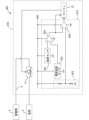
- First Embodiment 1 shows a vehicle 1 equipped with an abnormality determination device 10.
- the vehicle 1 includes a power storage unit 2, a load 3, and a power path 4.
- the power storage unit 2 is configured as, for example, a battery.
- the battery is, for example, a lead battery, a lithium ion battery, or the like.
- the load 3 is a load that can operate when the vehicle 1 is parked.
- the power path 4 is provided between the power storage unit 2 and the load 3.
- the power path 4 is a path that supplies power from the power storage unit 2 to the load 3.
- the vehicle 1 is in a started state when the start switch is on, and in a parked state when the start switch is off.
- the start switch may be an ignition switch, a power switch, or the like.
- the vehicle 1 When the vehicle 1 is in a parked state, it can supply dark current from the power storage unit 2 to the load 3 via the power path 4.
- the abnormality determination device 10 includes a relay 11, an abnormality detection unit 12, and a microcomputer 13 (hereinafter also referred to as MCU 13).
- the relay 11 corresponds to an example of an object to be judged.
- the relay 11 is provided in the power path 4.
- the relay 11 may be a mechanical relay having contacts, or may be a relay constituted by a semiconductor switching element.
- the relay 11 is of a normally-on type.
- the relay 11 is turned on when an on signal (in this embodiment, a low-level signal) is given, and is turned off when an off signal (in this embodiment, a high-level signal) is given.
- an on signal in this embodiment, a low-level signal
- an off signal in this embodiment, a high-level signal
- the abnormality detection unit 12 operates based on power from the power storage unit 2.
- the abnormality detection unit 12 detects that the relay 11 is in a first abnormal state and outputs a detection signal.
- the abnormality detection unit 12 determines that the relay 11 is in the first abnormal state when the temperature of the relay 11 exceeds a first threshold value.
- the abnormality detection unit 12 has a temperature sensor 21, a reference voltage generation circuit 22, and a comparison unit 23.
- the temperature sensor 21 is configured, for example, by a thermistor.
- the temperature sensor 21 detects the temperature of the relay 11 and outputs a signal indicating the detection value.
- the reference voltage generation circuit 22 generates and outputs a voltage corresponding to a first threshold value.
- the comparison unit 23 is configured, for example, as a comparator.
- the output value from the temperature sensor 21 is input to a non-inverting input terminal of the comparison unit 23.
- the output value from the reference voltage generation circuit 22 is input to an inverting input terminal of the comparison unit 23. If the output value from the temperature sensor 21 is greater than the output value from the reference voltage generation circuit 22, the comparison unit 23 outputs a detection signal (specifically, a high-level signal). If the output value from the temperature sensor 21 is smaller than the output value from the reference voltage generation circuit 22, the comparison unit 23 outputs a non-detection signal (specifically, a low-level signal).
- the abnormality detection unit 12 detects the first abnormal state based on the detection value of the temperature sensor 21. Specifically, the abnormality detection unit 12 determines whether or not the temperature of the relay 11 has exceeded a first threshold value. If the abnormality detection unit 12 determines that the temperature of the relay 11 has exceeded the first threshold value, it determines that the first abnormal state has occurred, and outputs a detection signal to the microcomputer 13. If the abnormality detection unit 12 determines that the temperature of the relay 11 has not exceeded the first threshold value, it determines that the first abnormal state has not occurred, and outputs a non-detection signal to the microcomputer 13.
- the microcomputer 13 includes a CPU, memory (e.g., ROM, RAM, flash memory, etc.), etc.
- the microcomputer 13 switches between an active state and a sleep state.
- the sleep state is a state in which power consumption is less than the active state.
- the microcomputer 13 goes into the sleep state when the vehicle 1 is in a parked state, and goes into the active state when the vehicle 1 is in a started state.
- the microcomputer 13 is configured to receive an on/off signal indicating the on/off state of the start switch, and determines whether the vehicle 1 is in a started state or a parked state based on the on/off signal.
- the microcomputer 13 In the activated state, the microcomputer 13 performs a determination process to determine whether the relay 11 is in the second abnormal state. When a detection signal is input in the sleep state, the microcomputer 13 switches to the activated state and performs the above determination process.
- the detection value of the temperature sensor 21 is input to the microcomputer 13.
- the microcomputer 13 determines whether or not the second abnormal state exists based on the detection value of the temperature sensor 21. Specifically, the microcomputer 13 determines that the second abnormal state exists when the temperature of the relay 11 exceeds a second threshold value.
- the second threshold value is a value greater than the first threshold value.
- the microcomputer 13 may immediately determine that the second abnormal state exists when the temperature of the relay 11 exceeds the second threshold value, or may determine that the second abnormal state exists when the state in which the temperature of the relay 11 exceeds the second threshold value continues for a predetermined time.
- the microcomputer 13 determines that the second abnormal state exists, it outputs an off signal (high level signal) to switch the relay 11 to the off state. This cuts off the power supply from the storage unit 2 to the load 3.
- step S11 the microcomputer 13 determines whether or not a detection signal has been input.
- the microcomputer 13 remains in a standby state until a detection signal is input.
- step S13 the microcomputer 13 determines whether or not a second abnormal state has occurred.
- the microcontroller 13 determines in step S14 whether or not the sleep condition is satisfied.
- the sleep condition includes, for example, the temperature of the relay 11 being lower than the third threshold value.
- the sleep condition is, for example, that the temperature of the relay 11 remains lower than the third threshold value for a predetermined period of time.
- the third threshold value may be the same value as the first threshold value, or may be a value lower than the first threshold value.
- the microcomputer 13 repeats the processing of steps S13 and S14 until it determines that the second abnormal state exists or that the sleep condition exists. If the microcomputer 13 determines that the sleep condition exists, it goes into a sleep state in step S15 and returns to step S11. If the microcomputer 13 determines that the second abnormal state exists, it switches the relay 11 to the off state in step S16. The microcomputer 13 then ends the processing shown in FIG. 2.
- the abnormality determination device 10 can reduce power consumption by putting the microcomputer 13 into a sleep state when the vehicle 1 is in a parked state. Furthermore, when the abnormality detection unit 12 detects that the relay 11 is in the first abnormal state, the abnormality determination device 10 can switch the microcomputer 13 into an active state and have it perform a determination process. Therefore, the abnormality determination device 10 can efficiently perform abnormality detection by the microcomputer 13 while reducing power consumption when the vehicle 1 is in a parked state.
- the abnormality determination device 10 can share the same temperature sensor 21 for detecting the first abnormal state and determining the second abnormal state.
- the abnormality determination device 10 can easily detect the first abnormal state by the abnormality detection unit 12 when the temperature of the relay 11 exceeds the second threshold value that is higher than the first threshold value. Therefore, when the temperature of the relay 11 exceeds the second threshold value, the abnormality determination device 10 can more reliably start up the microcomputer 13 and determine that the second abnormal state has occurred.
- the abnormality determination device 10 can cut off the power supply from the power storage unit 2 to the load 3 by the relay 11. Furthermore, because the relay 11 is of a normally-on type, the abnormality determination device 10 can reduce the power consumption required to maintain the relay 11 in the on state when power is being supplied from the power storage unit 2 to the load 3.
- the abnormality detection unit is a thermostat 212.
- the same components as those in the first embodiment are denoted by the same reference numerals, and detailed description thereof will be omitted.
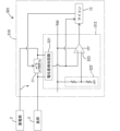
- FIG. 3 shows a vehicle 201 equipped with an abnormality determination device 210 according to the second embodiment.
- the vehicle 201 includes a power storage unit 2, a load 3, and a power line 4.
- the abnormality determination device 210 includes a relay 11, a thermostat 212, a microcontroller temperature sensor 30, and a microcontroller 13.
- the thermostat 212 corresponds to an example of an abnormality detection unit.
- the thermostat 212 detects that the relay 11 is in a first abnormal state and outputs a detection signal.
- the thermostat 212 determines that the relay 11 is in the first abnormal state and outputs a detection signal to the microcomputer 13.
- the microcomputer temperature sensor 30 is composed of, for example, a thermistor.
- the microcomputer temperature sensor 30 detects the temperature of the relay 11 and outputs a signal indicating the detected value to the microcomputer 13.
- the microcomputer 13 determines whether or not the second abnormal state exists based on the temperature detected by the microcomputer temperature sensor 30.
- the other operations of the microcomputer 13 are the same as those in the first embodiment.
- the abnormality detection unit is configured by the thermostat 212, so the configuration of the abnormality detection unit can be simplified.
- FIG. 4 shows a vehicle 301 equipped with an abnormality determination device 310 according to the third embodiment.
- the vehicle 301 includes a power storage unit 2, a load 3, and a power line 4.
- the abnormality determination device 310 includes a relay 11, an abnormality detection unit 12, a microcontroller temperature sensor 330, and a microcontroller 13.
- the microcomputer temperature sensor 330 is a sensor different from the temperature sensor 21 that the abnormality detection unit 12 has.
- the microcomputer temperature sensor 330 detects the temperature of the relay 11 with higher power consumption than the temperature sensor 21.
- the microcomputer temperature sensor 330 detects the temperature of the relay 11 with higher accuracy than the temperature sensor 21.
- the abnormality detection unit 12 detects that a first abnormal state exists based on the detection value of the temperature sensor 21.
- the operation of the abnormality detection unit 12 is the same as in the first embodiment.
- the microcomputer 13 determines whether or not the second abnormal state exists based on the detection value of the microcomputer temperature sensor 330.
- the other operations of the microcomputer 13 are the same as those in the first embodiment.
- the abnormality determination device 310 of the third embodiment can reduce the power consumption required for the abnormality detection unit 12 to detect the first abnormal state. Furthermore, the abnormality determination device 310 can determine the second abnormal state based on the detection value of the highly accurate microcomputer temperature sensor 330, and therefore can determine the second abnormal state with high accuracy.
- the first abnormal state and the second abnormal state are determined based on the difference between the temperature of the relay 11 and the environmental temperature at a position away from the relay 11.
- the same components as those in the first embodiment are denoted by the same reference numerals, and detailed description thereof will be omitted.
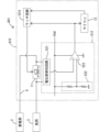
- FIG. 5 shows a vehicle 401 equipped with an abnormality determination device 410 according to the fourth embodiment.
- the vehicle 401 includes a power storage unit 2, a load 3, and a power line 4.
- the abnormality determination device 410 includes a relay 11, an abnormality detection unit 412, and a microcomputer 13.
- the abnormality detection unit 412 operates based on power from the power storage unit 2.
- the abnormality detection unit 412 detects that the relay 11 is in a first abnormal state and outputs a detection signal.
- the abnormality detection unit 412 has a temperature sensor 421, an environmental temperature sensor 422, a reference voltage generation circuit 423, a first comparison unit 424, and a second comparison unit 425. When the difference between the temperature of the relay 11 and the environmental temperature at a position away from the relay 11 exceeds a first threshold, the abnormality detection unit 412 determines that the first abnormal state has occurred and outputs a detection signal.
- the temperature sensor 421 is, for example, a thermistor.
- the temperature sensor 421 detects the temperature of the relay 11 and outputs a signal indicating the detected value.
- the environmental temperature sensor 422 is composed of, for example, a thermistor.
- the environmental temperature sensor 422 detects the environmental temperature at a position away from the relay 11 and outputs a signal indicating the detected value.
- the environmental temperature sensor 422 detects the environmental temperature at a position where the influence of heat generated by the relay 11 is small.
- the reference voltage generation circuit 423 generates and outputs a voltage equivalent to the first threshold value.
- the first comparison unit 424 is configured, for example, as a differential amplifier circuit.
- the output value from the temperature sensor 421 is input to the non-inverting input terminal of the first comparison unit 424.
- the output value from the environmental temperature sensor 422 is input to the inverting input terminal of the first comparison unit 424.
- the first comparison unit 424 outputs a voltage corresponding to the difference between the output value from the temperature sensor 421 and the output value from the reference voltage generation circuit 423. In other words, the first comparison unit 424 outputs the difference between the temperature of the relay 11 and the environmental temperature at a position away from the relay 11.
- the first comparison unit 424 outputs a value obtained by subtracting the environmental temperature from the temperature of the relay 11.
- the second comparison unit 425 is configured, for example, as a comparator.
- the output value from the first comparison unit 424 is input to a non-inverting input terminal of the second comparison unit 425.
- the output value from the reference voltage generation circuit 423 is input to an inverting input terminal of the second comparison unit 425. If the output value from the first comparison unit 424 is greater than the output value from the reference voltage generation circuit 423, the second comparison unit 425 outputs a detection signal (specifically, a high-level signal). If the output value from the first comparison unit 424 is less than the output value from the reference voltage generation circuit 423, the second comparison unit 425 outputs a non-detection signal (specifically, a low-level signal).
- the abnormality detection unit 412 determines whether the difference between the temperature of the relay 11 and the environmental temperature at a position away from the relay 11 exceeds a first threshold value. If the abnormality detection unit 412 determines that the difference between the temperature of the relay 11 and the environmental temperature exceeds the first threshold value, it determines that a first abnormal state exists, and outputs a detection signal to the microcontroller 13. If the abnormality detection unit 412 determines that the difference between the temperature of the relay 11 and the environmental temperature does not exceed the first threshold value, it determines that a first abnormal state does not exist, and outputs a non-detection signal to the microcontroller 13.
- the output value from the first comparison unit 424 (i.e., the difference between the temperature of the relay 11 and the environmental temperature) is input to the microcomputer 13.
- the microcomputer 13 determines whether or not the second abnormal state exists based on the difference between the temperature of the relay 11 and the environmental temperature. Specifically, the microcomputer 13 determines that the second abnormal state exists when the difference between the temperature of the relay 11 and the environmental temperature exceeds a second threshold value.
- the second threshold value is a value greater than the first threshold value.
- the microcomputer 13 may immediately determine that the second abnormal state exists when the difference between the temperature of the relay 11 and the environmental temperature exceeds the second threshold value, or may determine that the second abnormal state exists when the state in which the difference between the temperature of the relay 11 and the environmental temperature exceeds the second threshold value continues for a predetermined time.
- the microcomputer 13 determines that the second abnormal state exists, it outputs an off signal (high level signal) to switch the relay 11 to the off state. This cuts off the power supply from the power storage unit 2 to the load 3.
- the other operations of the microcomputer 13 are the same as those in the first embodiment.
- the abnormality determination device 410 of the fourth embodiment even if the detection accuracy by the abnormality detection unit 412 is low, when the difference between the temperature of the relay 11 and the ambient temperature exceeds the second threshold value that is greater than the first threshold value, the abnormality determination device 410 can more reliably start up the microcomputer 13 and determine that the second abnormality state exists when the difference between the temperature of the relay 11 and the ambient temperature exceeds the second threshold value.
- FIG. 6 shows a vehicle 501 equipped with an abnormality determination device 510 according to the fifth embodiment.
- the vehicle 501 includes a power storage unit 2, a load 3, and a power line 4.
- the abnormality determination device 510 includes a relay 11, an abnormality detection unit 512, and a microcomputer 13.
- the relay 11 is a mechanical relay having contacts.
- the abnormality detection unit 512 operates based on the power from the power storage unit 2.
- the power path 4 corresponds to an example of an object to be determined.
- the abnormality detection unit 512 determines that a first abnormal state exists when the current flowing through the power path 4 exceeds a first threshold value.
- the abnormality detection unit 512 has a potential difference detection circuit 521, a reference voltage generation circuit 522, and a comparison unit 523.
- the potential difference detection circuit 521 detects and outputs the potential difference between both ends of the relay 11. In other words, the potential difference detection circuit 521 detects the current flowing through the relay 11 and outputs a value indicating the current flowing through the relay 11.
- the potential difference detection circuit 521 is configured, for example, by a differential amplifier circuit.
- the reference voltage generation circuit 522 generates and outputs a voltage equivalent to the first threshold value.
- the comparison unit 523 is configured, for example, as a comparator.
- the output value from the potential difference detection circuit 521 is input to the non-inverting input terminal of the comparison unit 523.
- the output value from the reference voltage generation circuit 522 is input to the inverting input terminal of the comparison unit 523. If the output value from the potential difference detection circuit 521 is greater than the output value from the reference voltage generation circuit 522, the comparison unit 523 outputs a detection signal (specifically, a high-level signal). If the output value from the potential difference detection circuit 521 is less than the output value from the reference voltage generation circuit 522, the comparison unit 523 outputs a non-detection signal (specifically, a low-level signal).
- the abnormality detection unit 512 determines whether or not the current flowing through the relay 11 has exceeded the first threshold. If the abnormality detection unit 512 determines that the current flowing through the relay 11 has exceeded the first threshold, it determines that a first abnormal state has occurred, and outputs a detection signal to the microcontroller 13. If the abnormality detection unit 512 determines that the current flowing through the relay 11 has not exceeded the first threshold, it determines that a first abnormal state has not occurred, and outputs a non-detection signal to the microcontroller 13.
- the output value from the potential difference detection circuit 521 (i.e., a value indicating the current flowing through the relay 11) is input to the microcomputer 13.
- the microcomputer 13 determines that the second abnormal state exists when the current flowing through the relay 11 exceeds the second threshold.
- the second threshold is a value greater than the first threshold.
- the microcomputer 13 may immediately determine that the second abnormal state exists when the current flowing through the relay 11 exceeds the second threshold, or may determine that the second abnormal state exists when the state in which the current flowing through the relay 11 exceeds the second threshold continues for a predetermined time.
- the microcomputer 13 determines that the second abnormal state exists, it outputs an off signal (high level signal) to switch the relay 11 to the off state. This cuts off the power supply from the storage unit 2 to the load 3.
- the other operations of the microcomputer 13 are the same as those in the first embodiment.
- the abnormality determination device 510 can easily detect the first abnormal state by the abnormality detection unit 512 when the current flowing through the power path 4 exceeds the second threshold value that is greater than the first threshold value. Therefore, when the current flowing through the power path 4 exceeds the second threshold value, the abnormality determination device 510 can more reliably start up the microcomputer 13 and determine that the second abnormal state has occurred.
- the relay 11 is switched to the OFF state when the first abnormal state is detected, and the relay 11 is returned to the ON state when it is determined that the second abnormal state does not exist.
- the same components as those in the fifth embodiment are denoted by the same reference numerals, and detailed description thereof will be omitted.
- FIG. 7 shows a vehicle 601 equipped with an abnormality determination device 610 according to the sixth embodiment.
- the vehicle 601 includes a power storage unit 2, a load 3, and a power line 4.
- the abnormality determination device 610 includes a relay 11, an abnormality detection unit 512, a microcomputer 13, and a latch circuit 614.
- the latch circuit 614 selectively receives a detection signal and a non-detection signal output from the comparison unit 523 of the abnormality detection unit 512. When a detection signal is input, the latch circuit 614 switches the relay 11 to the off state. The latch circuit 614 maintains the relay 11 in the off state even after the detection signal is no longer input. The latch circuit 614 maintains the relay 11 in the off state until a release signal is input from the microcomputer 13. When a release signal is input, the latch circuit 614 returns the relay 11 to the on state.
- the microcomputer 13 determines whether or not the second abnormal state exists. In this embodiment, the microcomputer 13 determines that the second abnormal state exists when the number of times the device is started in response to the input of the detection signal reaches a predetermined upper limit, and determines that the second abnormal state does not exist when the upper limit has not been reached. When the microcomputer 13 determines that the second abnormal state does not exist, it outputs a release signal to the latch circuit 614, thereby returning the relay 11 to the on state.
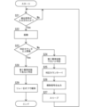
- step S21 the microcomputer 13 determines whether or not a detection signal has been input.
- the microcomputer 13 remains in a standby state until a detection signal is input.
- step S13 the microcomputer 13 determines whether or not the second abnormal state is occurring. Specifically, the microcomputer 13 determines whether or not the number in the determination counter is equal to or greater than the upper limit. The initial value of the determination counter is 0. Therefore, initially, the microcomputer 13 determines that the number in the determination counter is not equal to or greater than the upper limit. Then, in step S24, the microcomputer 13 determines that the second abnormal state is not occurring, and in step S25, the microcomputer 13 increments the determination counter by 1. The determination counter is incremented by 1 each time the microcomputer 13 is activated due to input of a detection signal and determines that the second abnormal state is not occurring.
- step S26 the microcomputer 13 outputs a release signal to the latch circuit 614, and in step S27, goes into a sleep state. After that, the microcomputer 13 returns to step S21.
- the microcomputer 13 repeats the process of steps S21 to S27, and when it determines in step S23 that the number in the determination counter is equal to or greater than the upper limit, it determines in step S28 that a second abnormal state exists.
- step S29 the microcomputer 13 maintains a state in which a release signal is not output, thereby maintaining the relay 11 in the off state. The microcomputer 13 then ends the process shown in FIG. 8.
- the microcomputer 13 may reset the number of judgment counters to 0 when a predetermined initialization condition is met. For example, when the number of judgment counters is 1 or more, the microcomputer 13 may be configured to wake up every time a predetermined time has elapsed after the sleep state even if a detection signal is not input, and may reset the number of judgment counters to 0 when the microcomputer 13 has been started a predetermined number of times without a detection signal being input. Alternatively, when the number of judgment counters is 1 or more, the microcomputer 13 may operate an RTC (Real Time Clock) in the sleep state, and may reset the number of judgment counters to 0 when a predetermined time has elapsed without a detection signal being input.
- RTC Real Time Clock
- the microcomputer 13 may be configured to wake up every time a predetermined time has elapsed after the sleep state even if a detection signal is not input, and may reset the number of judgment counters to 0 when the microcomputer 13 has been started in response to the passage of the predetermined time.
- the on-resistance of the relay 11 is used to detect the current flowing through the relay 11, but the current flowing through the relay 11 may be detected by another method.
- a shunt resistor may be provided in the power path 4, and the potential difference across the shunt resistor may be detected by the potential difference detection circuit 521.
- the current flowing through the relay 11 may be detected by a magnetic sensor such as a Hall element.
Landscapes
- Engineering & Computer Science (AREA)
- Mechanical Engineering (AREA)
- Protection Of Static Devices (AREA)
Abstract
Description
本開示は、異常判定装置に関する。 This disclosure relates to an abnormality determination device.
特許文献1には、マイクロコンピュータを備える車両用電子制御装置が開示されている。マイクロコンピュータは、始動スイッチのオフ切り替え時にその都度の車載バッテリの充電状態と車載機器の起動に伴い要する消費電力とを比較する。マイクロコンピュータは、バッテリ充電状態が許容レベルにあれば放置時間計測タイマを起動する。車両用電子制御装置においては、放置時間計測タイマによる所定の車両放置時間経過時にマイクロコンピュータにより車載機器が起動される。マイクロコンピュータは、始動スイッチのオフ後、所定の車両放置時間経過時に車載機器を用いて各種の異常診断を行う。 Patent Document 1 discloses an electronic control device for a vehicle that includes a microcomputer. Each time the start switch is turned off, the microcomputer compares the charge state of the vehicle battery with the power consumption required to start up the vehicle equipment. If the battery charge state is at an acceptable level, the microcomputer starts a timer measuring the amount of time the vehicle has been left unattended. In the vehicle electronic control device, the microcomputer starts up the vehicle equipment when a predetermined amount of time has elapsed since the timer indicates that the vehicle has been left unattended. After the start switch is turned off, the microcomputer uses the vehicle equipment to diagnose various abnormalities when the predetermined amount of time has elapsed since the vehicle was left unattended.
特許文献1の構成では、異常診断を行うタイミングが車両放置時間経過時に限られてしまう。異常を早めに検出する方法としては、例えば、マイクロコンピュータ及び車載機器を所定時間ごとに起動させ、所定時間ごとに異常診断を行わせることが考えられる。しかし、この構成では、異常を素早く検出しようとするほど、所定時間を短くする必要があり、マイクロコンピュータによる消費電力が大きくなるという問題がある。 In the configuration of Patent Document 1, the timing for abnormality diagnosis is limited to when the vehicle has been left unattended for a certain period of time. One possible method for detecting abnormalities early is, for example, to start up the microcomputer and on-board equipment at predetermined intervals and have abnormality diagnosis performed at each predetermined interval. However, with this configuration, the more quickly an abnormality is to be detected, the shorter the predetermined period must be, which poses the problem of increased power consumption by the microcomputer.
本開示は、車両の駐車状態において消費電力を抑えつつマイクロコンピュータによる異常検出を効率的に行うことが可能な技術を提供することを目的とする。 The purpose of this disclosure is to provide technology that enables efficient anomaly detection by a microcomputer while reducing power consumption when the vehicle is parked.
本開示の異常判定装置は、
車両に搭載される異常判定装置であって、
前記車両に設けられる判定対象が第1異常状態であることを検出して検出信号を出力する異常検出部と、
起動状態において前記判定対象が第2異常状態であるか否かを判定する判定処理を行うマイクロコンピュータと、を備え、
前記マイクロコンピュータは、前記車両が駐車状態となった場合にスリープ状態となり、前記スリープ状態において前記検出信号が入力された場合に前記起動状態に切り替わり前記判定処理を行う。
The abnormality determination device of the present disclosure is
An abnormality determination device mounted on a vehicle,
an abnormality detection unit provided in the vehicle that detects that the determination target is in a first abnormal state and outputs a detection signal;
a microcomputer that performs a determination process to determine whether the determination target is in a second abnormal state in a startup state,
The microcomputer goes into a sleep state when the vehicle is parked, and switches to the wake-up state when the detection signal is input in the sleep state to perform the determination process.
本開示に係る技術は、車両の駐車状態において消費電力を抑えつつマイクロコンピュータによる異常検出を効率的に行うことができる。 The technology disclosed herein can efficiently detect abnormalities using a microcomputer while reducing power consumption when the vehicle is parked.
[本開示の実施形態の説明]
以下では、本開示に係る実施形態が列記されて例示される。
[Description of the embodiments of the present disclosure]
Below, embodiments according to the present disclosure are listed and illustrated.
〔1〕車両に搭載される異常判定装置であって、
前記車両に設けられる判定対象が第1異常状態であることを検出して検出信号を出力する異常検出部と、
起動状態において前記判定対象が第2異常状態であるか否かを判定する判定処理を行うマイクロコンピュータと、を備え、
前記マイクロコンピュータは、前記車両が駐車状態となった場合にスリープ状態となり、前記スリープ状態において前記検出信号が入力された場合に前記起動状態に切り替わり前記判定処理を行う
異常判定装置。
[1] An abnormality determination device mounted on a vehicle,
an abnormality detection unit provided in the vehicle that detects that the determination target is in a first abnormal state and outputs a detection signal;
a microcomputer that performs a determination process to determine whether the determination target is in a second abnormal state in a startup state,
The microcomputer goes into a sleep state when the vehicle is parked, and switches to the wake-up state and performs the determination process when the detection signal is input in the sleep state.
上記異常判定装置は、車両が駐車状態となった場合にマイクロコンピュータをスリープ状態にして消費電力を抑えることができる。しかも、上記異常判定装置は、異常検出部によって判定対象が第1異常状態であることを検出した場合に、マイクロコンピュータを起動状態に切り替えて判定処理を行わせることができる。したがって、上記異常判定装置は、車両の駐車状態において消費電力を抑えつつマイクロコンピュータによる異常検出を効率的に行うことができる。 The abnormality determination device can reduce power consumption by putting the microcomputer into a sleep state when the vehicle is in a parked state. Furthermore, when the abnormality detection unit detects that the object to be determined is in the first abnormal state, the abnormality determination device can switch the microcomputer into an active state and cause it to perform the determination process. Therefore, the abnormality determination device can efficiently perform abnormality detection by the microcomputer while reducing power consumption when the vehicle is in a parked state.
〔2〕前記判定対象は、リレーであり、
前記異常検出部は、前記リレーの温度が第1閾値を超えた場合に前記第1異常状態であると判定し、
前記マイクロコンピュータは、前記リレーの温度が前記第1閾値よりも大きい第2閾値を超えた場合に前記第2異常状態であると判定する
〔1〕に記載の異常判定装置。
[2] The object to be judged is a relay,
The abnormality detection unit determines that the first abnormal state occurs when a temperature of the relay exceeds a first threshold value,
The abnormality determination device according to claim 1, wherein the microcomputer determines that the second abnormal state occurs when the temperature of the relay exceeds a second threshold value that is greater than the first threshold value.
上記異常判定装置は、異常検出部による検出精度が低くとも、リレーの温度が第1閾値よりも大きい第2閾値を超えた状態では、異常検出部によって第1異常状態を検出しやすい。このため、上記異常判定装置は、リレーの温度が第2閾値を超えた場合に、より確実にマイクロコンピュータを起動させ、第2異常状態であると判定することができる。 Even if the detection accuracy of the abnormality detection unit is low, the abnormality determination device is likely to detect the first abnormal state when the temperature of the relay exceeds a second threshold value that is higher than the first threshold value. Therefore, when the temperature of the relay exceeds the second threshold value, the abnormality determination device can more reliably start up the microcomputer and determine that the second abnormal state has occurred.
〔3〕前記異常検出部は、前記リレーの温度を検出する温度センサを有し、前記温度センサの検出値に基づいて前記第1異常状態であることを検出し、
前記マイクロコンピュータは、前記温度センサの検出値に基づいて前記第2異常状態であるか否かを判定する
〔2〕に記載の異常判定装置。
[3] the abnormality detection unit has a temperature sensor that detects a temperature of the relay, and detects that the first abnormal state is occurring based on a detection value of the temperature sensor;
The abnormality determination device according to [2], wherein the microcomputer determines whether or not the second abnormal state occurs based on a detection value of the temperature sensor.
上記異常判定装置は、第1異常状態の検出と第2異常状態の判定とで同じ温度センサを共用することができる。 The abnormality determination device can share the same temperature sensor for detecting the first abnormal state and determining the second abnormal state.
〔4〕前記異常検出部は、前記リレーの温度を検出する温度センサを有し、
さらに、前記温度センサとは異なるマイコン用温度センサを備え、
前記マイコン用温度センサは、前記温度センサよりも高い消費電力で前記リレーの温度を検出し、
前記異常検出部は、前記温度センサの検出値に基づいて前記第1異常状態であることを検出し、
前記マイクロコンピュータは、前記マイコン用温度センサの検出値に基づいて前記第2異常状態であるか否かを判定する
〔2〕に記載の異常判定装置。
[4] The abnormality detection unit has a temperature sensor that detects a temperature of the relay,
Further, a temperature sensor for a microcomputer different from the temperature sensor is provided,
the microcomputer temperature sensor detects the temperature of the relay with a higher power consumption than the temperature sensor;
the abnormality detection unit detects that the first abnormal state is occurring based on a detection value of the temperature sensor,
The abnormality determination device according to [2], wherein the microcomputer determines whether or not the second abnormal state occurs based on a detection value of the microcomputer temperature sensor.
上記異常判定装置は、異常検出部が第1異常状態を検出するために要する消費電力を抑えることができる。また、上記異常判定装置は、マイコン用温度センサとして高精度のセンサを採用しやすい。 The abnormality determination device can reduce the power consumption required for the abnormality detection unit to detect the first abnormal state. In addition, the abnormality determination device can easily use a high-precision sensor as the microcomputer temperature sensor.
〔5〕前記判定対象は、リレーであり、
前記異常検出部は、前記リレーの温度と前記リレーから離れた位置における環境温度との差が第1閾値を超えた場合に前記第1異常状態であると判定し、
前記マイクロコンピュータは、前記差が前記第1閾値よりも大きい第2閾値を超えた場合に前記第2異常状態であると判定する
〔1〕に記載の異常判定装置。
[5] The object to be judged is a relay,
the abnormality detection unit determines that the first abnormal state occurs when a difference between a temperature of the relay and an environmental temperature at a position away from the relay exceeds a first threshold value;
The abnormality determination device according to [1], wherein the microcomputer determines that the second abnormal state occurs when the difference exceeds a second threshold value that is greater than the first threshold value.
上記異常判定装置は、異常検出部による検出精度が低くとも、リレーの温度と環境温度との差が第1閾値よりも大きい第2閾値を超えた状態では、異常検出部によって第1異常状態を検出しやすい。このため、上記異常判定装置は、リレーの温度と環境温度との差が第2閾値を超えた場合に、より確実にマイクロコンピュータを起動させ、第2異常状態であると判定することができる。 Even if the detection accuracy of the abnormality detection unit is low, the abnormality determination device is likely to detect the first abnormal state by the abnormality detection unit when the difference between the relay temperature and the environmental temperature exceeds a second threshold value that is greater than the first threshold value. Therefore, the abnormality determination device can more reliably start up the microcomputer and determine that the second abnormal state exists when the difference between the relay temperature and the environmental temperature exceeds the second threshold value.
〔6〕前記判定対象は、蓄電部から負荷へ電力を供給する電力路であり、
前記異常検出部は、前記電力路を流れる電流が第1閾値を超えた場合に前記第1異常状態であると判定し、
前記マイクロコンピュータは、前記電力路を流れる電流が前記第1閾値よりも大きい第2閾値を超えた場合に前記第2異常状態であると判定する
〔1〕に記載の異常判定装置。
[6] The object to be determined is a power path that supplies power from a power storage unit to a load,
The abnormality detection unit determines that the first abnormal state occurs when a current flowing through the power path exceeds a first threshold value,
The abnormality determination device according to claim 1, wherein the microcomputer determines that the second abnormal state occurs when the current flowing through the power path exceeds a second threshold value that is greater than the first threshold value.
上記異常判定装置は、異常検出部による検出精度が低くとも、電力路を流れる電流が第1閾値よりも大きい第2閾値を超えた状態では、異常検出部によって第1異常状態を検出しやすい。このため、上記異常判定装置は、電力路を流れる電流が第2閾値を超えた場合に、より確実にマイクロコンピュータを起動させ、第2異常状態であると判定することができる。 Even if the detection accuracy of the abnormality detection unit is low, the abnormality determination device can easily detect the first abnormal state by the abnormality detection unit when the current flowing through the power path exceeds a second threshold value that is greater than the first threshold value. Therefore, the abnormality determination device can more reliably start up the microcomputer and determine that the second abnormal state has occurred when the current flowing through the power path exceeds the second threshold value.
〔7〕蓄電部から負荷へ電力を供給する電力路に設けられるリレーを備え、
前記リレーは、前記異常検出部によって前記第1異常状態が検出された場合に、オン状態からオフ状態に切り替わり、前記マイクロコンピュータによって前記第2異常状態でないと判定された場合に、オフ状態からオン状態に復帰する
〔1〕に記載の異常判定装置。
[7] A relay is provided in a power path that supplies power from the storage unit to a load,
The abnormality determination device according to claim 1, wherein the relay switches from an on state to an off state when the first abnormality state is detected by the abnormality detection unit, and returns from the off state to the on state when the microcomputer determines that the second abnormality state does not exist.
上記異常判定装置は、第1異常状態が検出された時点で蓄電部から負荷への電力供給を遮断することができ、その後、第2異常状態でないと判定された場合にはリレーをオン状態に復帰させることができる。 The abnormality determination device can cut off the power supply from the power storage unit to the load when the first abnormality state is detected, and can then return the relay to the on state if it is determined that the second abnormality state does not exist.
〔8〕蓄電部から負荷へ電力を供給する電力路に設けられるリレーを備え、
前記リレーは、ノーマリオン型であり、
前記マイクロコンピュータは、前記第2異常状態であると判定した場合に、前記リレーをオフ状態に制御する
〔1〕から〔7〕のいずれか一つに記載の異常判定装置。
[8] A relay is provided in a power path that supplies power from the power storage unit to a load,
the relay is of a normally-on type,
The abnormality determination device according to any one of [1] to [7], wherein the microcomputer controls the relay to an off state when it determines that the second abnormal state exists.
上記異常判定装置は、マイクロコンピュータによって第2異常状態であると判定された場合に、リレーによって蓄電部から負荷への電力供給を遮断することができる。しかも、上記異常判定装置は、リレーがノーマリオン型であるため、蓄電部から負荷へ電力を供給する状態において、リレーをオン状態に維持するための消費電力を抑えることができる。 The abnormality determination device can cut off the power supply from the power storage unit to the load by the relay when the microcomputer determines that the second abnormal state exists. Furthermore, because the relay in the abnormality determination device is of the normally-on type, the power consumption required to maintain the relay in the on state can be reduced when power is being supplied from the power storage unit to the load.
[本開示の実施形態の詳細]
<第1実施形態>
図1には、異常判定装置10を搭載する車両1が示されている。車両1は、蓄電部2と、負荷3と、電力路4と、を備える。蓄電部2は、例えばバッテリとして構成される。バッテリは、例えば鉛バッテリ、リチウムイオンバッテリなどである。負荷3は、車両1の駐車状態において動作し得る負荷である。電力路4は、蓄電部2と負荷3との間に設けられる。電力路4は、蓄電部2から負荷3へ電力を供給する経路である。
[Details of the embodiment of the present disclosure]
First Embodiment
1 shows a vehicle 1 equipped with an
車両1は、始動スイッチがオン状態のときに始動状態となり、オフ状態のときに駐車状態となる。始動スイッチは、イグニッションスイッチ、パワースイッチなどである。車両1は、駐車状態において電力路4を介して蓄電部2から負荷3に暗電流を供給し得る。
The vehicle 1 is in a started state when the start switch is on, and in a parked state when the start switch is off. The start switch may be an ignition switch, a power switch, or the like. When the vehicle 1 is in a parked state, it can supply dark current from the
異常判定装置10は、リレー11と、異常検出部12と、マイクロコンピュータ13(以下、マイコン13とも称する)と、を備える。
The
リレー11は、判定対象の一例に相当する。リレー11は、電力路4に設けられる。リレー11は、接点を有する機械式のリレーであってもよいし、半導体スイッチング素子によって構成されるリレーであってもよい。リレー11は、本実施形態では、ノーマリオン型である。リレー11は、オン信号(本実施形態では、ローレベル信号)が与えられるときにオン状態となり、オフ信号(本実施形態では、ハイレベル信号)が与えられるときにオフ状態となる。リレー11は、オン状態のときに蓄電部2から負荷3への電力供給を許容し、オフ状態のときに蓄電部2から負荷3への電力供給を遮断する。
The
異常検出部12は、蓄電部2からの電力に基づいて動作する。異常検出部12は、リレー11が第1異常状態であることを検出して検出信号を出力する。異常検出部12は、リレー11の温度が第1閾値を超えた場合に第1異常状態であると判定する。異常検出部12は、温度センサ21と、基準電圧生成回路22と、比較部23と、を有する。
The
温度センサ21は、例えばサーミスタによって構成される。温度センサ21は、リレー11の温度を検出し、検出値を示す信号を出力する。基準電圧生成回路22は、第1閾値に相当する電圧を生成して出力する。比較部23は、例えばコンパレータとして構成される。比較部23の非反転入力端子には、温度センサ21からの出力値が入力される。比較部23の反転入力端子には、基準電圧生成回路22からの出力値が入力される。比較部23は、温度センサ21からの出力値が基準電圧生成回路22からの出力値よりも大きい場合、検出信号(具体的には、ハイレベル信号)を出力する。比較部23は、温度センサ21からの出力値が基準電圧生成回路22からの出力値よりも小さい場合、非検出信号(具体的には、ローレベル信号)を出力する。
The
つまり、異常検出部12は、温度センサ21の検出値に基づいて第1異常状態であることを検出する。具体的には、異常検出部12は、リレー11の温度が第1閾値を超えたか否かを判定する。異常検出部12は、リレー11の温度が第1閾値を超えたと判定した場合に第1異常状態であると判定し、マイコン13に向けて検出信号を出力する。異常検出部12は、リレー11の温度が第1閾値を超えていないと判定した場合に第1異常状態でないと判定し、マイコン13に向けて非検出信号を出力する。
In other words, the
マイコン13は、CPU、メモリ(例えば、ROM、RAM、フラッシュメモリなど)などを含む。マイコン13は、起動状態とスリープ状態とに切り替わる。スリープ状態は、起動状態よりも消費電力が小さい状態である。マイコン13は、車両1が駐車状態となった場合にスリープ状態となり、車両1が始動状態となった場合に起動状態となる。マイコン13には、始動スイッチのオンオフ状態を示すオンオフ信号が入力される構成となっており、オンオフ信号に基づいて車両1が始動状態であるか駐車状態であるかを判定する。
The
マイコン13は、起動状態においてリレー11が第2異常状態であるか否かを判定する判定処理を行う。マイコン13は、スリープ状態において検出信号が入力された場合に起動状態に切り替わり、上記判定処理を行う。
In the activated state, the
マイコン13には、温度センサ21の検出値が入力される。マイコン13は、温度センサ21の検出値に基づいて第2異常状態であるか否かを判定する。具体的には、マイコン13は、リレー11の温度が第2閾値を超えた場合に第2異常状態であると判定する。第2閾値は、第1閾値よりも大きい値である。マイコン13は、リレー11の温度が第2閾値を超えた場合に、直ちに第2異常状態であると判定してもよいし、リレー11の温度が第2閾値を超える状態が所定時間継続した場合に第2異常状態であると判定してもよい。マイコン13は、第2異常状態であると判定した場合、オフ信号(ハイレベル信号)を出力して、リレー11をオフ状態に切り替える。これにより、蓄電部2から負荷3への電力供給が遮断される。
The detection value of the
マイコン13は、例えば車両1が駐車状態となったことに起因してスリープ状態に切り替わった場合、図2に示す処理を行う。マイコン13は、ステップS11にて、検出信号が入力されたか否かを判定する。マイコン13は、検出信号が入力されるまで待機状態となる。
When the
マイコン13は、検出信号が入力されたと判定した場合、ステップS12にて、起動状態となる。そして、マイコン13は、ステップS13にて、第2異常状態であるか否かを判定する。
If the
マイコン13は、第2異常状態でないと判定した場合、ステップS14にて、スリープ条件が成立したか否かを判定する。スリープ条件は、例えば、リレー11の温度が第3閾値よりも小さいことを含む。スリープ条件は、例えば、リレー11の温度が第3閾値よりも小さい状態が所定時間継続したことである。第3閾値は、第1閾値と同じ値であってもよいし、第1閾値よりも小さい値であってもよい。
If the
マイコン13は、第2異常状態であると判定するか、スリープ条件が成立したと判定するまで、ステップS13,S14の処理を繰り返す。マイコン13は、スリープ条件が成立したと判定した場合、ステップS15にて、スリープ状態となり、ステップS11に戻る。マイコン13は、第2異常状態であると判定した場合、ステップS16にて、リレー11をオフ状態に切り替える。その後、マイコン13は、図2に示す処理を終了する。
The
以上のように、異常判定装置10は、車両1が駐車状態となった場合にマイコン13をスリープ状態にして消費電力を抑えることができる。しかも、異常判定装置10は、異常検出部12によってリレー11が第1異常状態であることを検出した場合に、マイコン13を起動状態に切り替えて判定処理を行わせることができる。したがって、異常判定装置10は、車両1の駐車状態において消費電力を抑えつつマイコン13による異常検出を効率的に行うことができる。
As described above, the
異常判定装置10は、第1異常状態の検出と第2異常状態の判定とで同じ温度センサ21を共用することができる。
The
異常判定装置10は、異常検出部12による検出精度が低くとも、リレー11の温度が第1閾値よりも大きい第2閾値を超えた状態では、異常検出部12によって第1異常状態を検出しやすい。このため、異常判定装置10は、リレー11の温度が第2閾値を超えた場合に、より確実にマイコン13を起動させ、第2異常状態であると判定することができる。
Even if the detection accuracy of the
異常判定装置10は、マイコン13によって第2異常状態であると判定された場合に、リレー11によって蓄電部2から負荷3への電力供給を遮断することができる。しかも、異常判定装置10は、リレー11がノーマリオン型であるため、蓄電部2から負荷3へ電力を供給する状態において、リレー11をオン状態に維持するための消費電力を抑えることができる。
When the
<第2実施形態>
第2実施形態では、異常検出部がサーモスタット212である例について説明する。なお、第2実施形態では、第1実施形態と同じ構成については同じ符号を付し、詳しい説明を省略する。
Second Embodiment
In the second embodiment, an example will be described in which the abnormality detection unit is a
図3には、第2実施形態の異常判定装置210を搭載する車両201が示されている。車両201は、蓄電部2と、負荷3と、電力路4と、を備える。
FIG. 3 shows a
異常判定装置210は、リレー11と、サーモスタット212と、マイコン用温度センサ30と、マイコン13と、を備える。
The
サーモスタット212は、異常検出部の一例に相当する。サーモスタット212は、リレー11が第1異常状態であることを検出して検出信号を出力する。サーモスタット212は、リレー11の温度が第1閾値を超えた場合に第1異常状態であると判定し、マイコン13に向けて検出信号を出力する。
The
マイコン用温度センサ30は、例えばサーミスタによって構成される。マイコン用温度センサ30は、リレー11の温度を検出し、検出値を示す信号をマイコン13に向けて出力する。
The
マイコン13は、マイコン用温度センサ30によって検出された温度に基づいて、第2異常状態であるか否かを判定する。マイコン13のその他の動作は、第1実施形態と同じである。
The
第2実施形態の異常判定装置210は、異常検出部がサーモスタット212によって構成されるため、異常検出部の構成を簡素化することができる。
In the second embodiment of the
<第3実施形態>
第3実施形態では、温度センサ21の検出値に基づいて第1異常状態であることを検出し、マイコン用温度センサ30の検出値に基づいて第2異常状態であるか否かを判定する例について説明する。なお、第3実施形態では、第1実施形態と同じ構成については同じ符号を付し、詳しい説明を省略する。
Third Embodiment
In the third embodiment, an example will be described in which a first abnormal state is detected based on a detection value of the
図4には、第3実施形態の異常判定装置310を搭載する車両301が示されている。車両301は、蓄電部2と、負荷3と、電力路4と、を備える。
FIG. 4 shows a
異常判定装置310は、リレー11と、異常検出部12と、マイコン用温度センサ330と、マイコン13と、を備える。
The
マイコン用温度センサ330は、異常検出部12が有する温度センサ21とは異なるセンサである。マイコン用温度センサ330は、温度センサ21よりも高い消費電力でリレー11の温度を検出する。マイコン用温度センサ330は、温度センサ21よりも高い精度でリレー11の温度を検出する。
The
異常検出部12は、温度センサ21の検出値に基づいて第1異常状態であることを検出する。異常検出部12の動作は、第1実施形態と同じである。
The
マイコン13は、マイコン用温度センサ330の検出値に基づいて第2異常状態であるか否かを判定する。マイコン13のその他の動作は、第1実施形態と同じである。
The
以上のように、第3実施形態の異常判定装置310は、異常検出部12が第1異常状態を検出するために要する消費電力を抑えることができる。また、異常判定装置310は、高精度のマイコン用温度センサ330の検出値に基づいて第2異常状態を判定することができるため、第2異常状態を高精度で判定することができる。
As described above, the
<第4実施形態>
第4実施形態では、リレー11の温度とリレー11から離れた位置における環境温度との差に基づいて第1異常状態及び第2異常状態を判定する例について説明する。なお、第4実施形態では、第1実施形態と同じ構成については同じ符号を付し、詳しい説明を省略する。
Fourth Embodiment
In the fourth embodiment, an example will be described in which the first abnormal state and the second abnormal state are determined based on the difference between the temperature of the
図5には、第4実施形態の異常判定装置410を搭載する車両401が示されている。車両401は、蓄電部2と、負荷3と、電力路4と、を備える。
FIG. 5 shows a
異常判定装置410は、リレー11と、異常検出部412と、マイコン13と、を備える。
The
異常検出部412は、蓄電部2からの電力に基づいて動作する。異常検出部412は、リレー11が第1異常状態であることを検出して検出信号を出力する。異常検出部412は、温度センサ421と、環境温度センサ422と、基準電圧生成回路423と、第1比較部424と、第2比較部425と、を有する。異常検出部412は、リレー11の温度とリレー11から離れた位置における環境温度との差が第1閾値を超えた場合に第1異常状態であると判定して、検出信号を出力する。
The
温度センサ421は、例えばサーミスタによって構成される。温度センサ421は、リレー11の温度を検出し、検出値を示す信号を出力する。
The
環境温度センサ422は、例えばサーミスタによって構成される。環境温度センサ422は、リレー11から離れた位置における環境温度を検出し、検出値を示す信号を出力する。環境温度センサ422は、リレー11の発熱の影響が小さい位置における環境温度を検出する。
The
基準電圧生成回路423は、第1閾値に相当する電圧を生成して出力する。
The reference
第1比較部424は、例えば差動増幅回路として構成される。第1比較部424の非反転入力端子には、温度センサ421からの出力値が入力される。第1比較部424の反転入力端子には、環境温度センサ422からの出力値が入力される。第1比較部424は、温度センサ421からの出力値と基準電圧生成回路423からの出力値との差に応じた電圧を出力する。つまり、第1比較部424は、リレー11の温度とリレー11からの離れた位置における環境温度との差を出力する。第1比較部424は、リレー11の温度から環境温度を差し引いた値を出力する。
The
第2比較部425は、例えばコンパレータとして構成される。第2比較部425の非反転入力端子には、第1比較部424からの出力値が入力される。第2比較部425の反転入力端子には、基準電圧生成回路423からの出力値が入力される。第2比較部425は、第1比較部424からの出力値が基準電圧生成回路423からの出力値よりも大きい場合、検出信号(具体的には、ハイレベル信号)を出力する。第2比較部425は、第1比較部424からの出力値が基準電圧生成回路423からの出力値よりも小さい場合、非検出信号(具体的には、ローレベル信号)を出力する。
The
つまり、異常検出部412は、リレー11の温度とリレー11から離れた位置における環境温度との差が第1閾値を超えたか否かを判定する。異常検出部412は、リレー11の温度と環境温度との差が第1閾値を超えたと判定した場合に第1異常状態であると判定し、マイコン13に向けて検出信号を出力する。異常検出部412は、リレー11の温度と環境温度との差が第1閾値を超えていないと判定した場合に第1異常状態でないと判定し、マイコン13に向けて非検出信号を出力する。
In other words, the
マイコン13には、第1比較部424からの出力値(つまり、リレー11の温度と環境温度との差)が入力される。マイコン13は、リレー11の温度と環境温度との差に基づいて第2異常状態であるか否かを判定する。具体的には、マイコン13は、リレー11の温度と環境温度との差が第2閾値を超えた場合に第2異常状態であると判定する。第2閾値は、第1閾値よりも大きい値である。マイコン13は、リレー11の温度と環境温度との差が第2閾値を超えた場合に、直ちに第2異常状態であると判定してもよいし、リレー11の温度と環境温度との差が第2閾値を超える状態が所定時間継続した場合に第2異常状態であると判定してもよい。マイコン13は、第2異常状態であると判定した場合、オフ信号(ハイレベル信号)を出力して、リレー11をオフ状態に切り替える。これにより、蓄電部2から負荷3への電力供給が遮断される。マイコン13のその他の動作は、第1実施形態と同じである。
The output value from the first comparison unit 424 (i.e., the difference between the temperature of the
以上のように、第4実施形態の異常判定装置410は、異常検出部412による検出精度が低くとも、リレー11の温度と環境温度との差が第1閾値よりも大きい第2閾値を超えた状態では、異常検出部412によって第1異常状態を検出しやすい。このため、異常判定装置410は、リレー11の温度と環境温度との差が第2閾値を超えた場合に、より確実にマイコン13を起動させ、第2異常状態であると判定することができる。
As described above, in the
<第5実施形態>
第5実施形態では、電力路4を流れる電流に基づいて第1異常状態及び第2異常状態を判定する例について説明する。なお、第5実施形態では、第1実施形態と同じ構成については同じ符号を付し、詳しい説明を省略する。
Fifth Embodiment
In the fifth embodiment, an example will be described in which a first abnormal state and a second abnormal state are determined based on a current flowing through an
図6には、第5実施形態の異常判定装置510を搭載する車両501が示されている。車両501は、蓄電部2と、負荷3と、電力路4と、を備える。
FIG. 6 shows a
異常判定装置510は、リレー11と、異常検出部512と、マイコン13と、を備える。リレー11は、本実施形態では、接点を有する機械式のリレーである。
The
異常検出部512は、蓄電部2からの電力に基づいて動作する。本実施形態では、電力路4が判定対象の一例に相当する。異常検出部12は、電力路4を流れる電流が第1閾値を超えた場合に第1異常状態であると判定する。異常検出部512は、電位差検知回路521と、基準電圧生成回路522と、比較部523と、を有する。
The
電位差検知回路521は、リレー11の両端の電位差を検知して出力する。つまり、電位差検知回路521は、リレー11を流れる電流を検知し、リレー11を流れる電流を示す値を出力する。電位差検知回路521は、例えば差動増幅回路によって構成される。
The potential
基準電圧生成回路522は、第1閾値に相当する電圧を生成して出力する。
The reference
比較部523は、例えばコンパレータとして構成される。比較部523の非反転入力端子には、電位差検知回路521からの出力値が入力される。比較部523の反転入力端子には、基準電圧生成回路522からの出力値が入力される。比較部523は、電位差検知回路521からの出力値が基準電圧生成回路522からの出力値よりも大きい場合、検出信号(具体的には、ハイレベル信号)を出力する。比較部523は、電位差検知回路521からの出力値が基準電圧生成回路522からの出力値よりも小さい場合、非検出信号(具体的には、ローレベル信号)を出力する。
The
つまり、異常検出部512は、リレー11を流れる電流が第1閾値を超えたか否かを判定する。異常検出部512は、リレー11を流れる電流が第1閾値を超えたと判定した場合に第1異常状態であると判定し、マイコン13に向けて検出信号を出力する。異常検出部512は、リレー11を流れる電流が第1閾値を超えていないと判定した場合に第1異常状態でないと判定し、マイコン13に向けて非検出信号を出力する。
In other words, the
マイコン13には、電位差検知回路521からの出力値(つまり、リレー11を流れる電流を示す値)が入力される。マイコン13は、リレー11を流れる電流が第2閾値を超えた場合に第2異常状態であると判定する。第2閾値は、第1閾値よりも大きい値である。マイコン13は、リレー11を流れる電流が第2閾値を超えた場合に、直ちに第2異常状態であると判定してもよいし、リレー11を流れる電流が第2閾値を超える状態が所定時間継続した場合に第2異常状態であると判定してもよい。マイコン13は、第2異常状態であると判定した場合、オフ信号(ハイレベル信号)を出力して、リレー11をオフ状態に切り替える。これにより、蓄電部2から負荷3への電力供給が遮断される。マイコン13のその他の動作は、第1実施形態と同じである。
The output value from the potential difference detection circuit 521 (i.e., a value indicating the current flowing through the relay 11) is input to the
以上のように、異常判定装置510は、異常検出部512による検出精度が低くとも、電力路4を流れる電流が第1閾値よりも大きい第2閾値を超えた状態では、異常検出部512によって第1異常状態を検出しやすい。このため、異常判定装置510は、電力路4を流れる電流が第2閾値を超えた場合に、より確実にマイコン13を起動させ、第2異常状態であると判定することができる。
As described above, even if the detection accuracy of the
<第6実施形態>
第6実施形態では、第1異常状態が検出された時点でリレー11がオフ状態に切り替わり、第2異常状態でないと判定された場合にリレー11がオン状態に復帰する例について説明する。なお、第6実施形態では、第5実施形態と同じ構成については同じ符号を付し、詳しい説明を省略する。
Sixth Embodiment
In the sixth embodiment, an example will be described in which the
図7には、第6実施形態の異常判定装置610を搭載する車両601が示されている。車両601は、蓄電部2と、負荷3と、電力路4と、を備える。
FIG. 7 shows a
異常判定装置610は、リレー11と、異常検出部512と、マイコン13と、ラッチ回路614と、を備える。
The
ラッチ回路614には、異常検出部512の比較部523から出力される検出信号及び非検出信号が選択的に入力される。ラッチ回路614は、検出信号が入力された場合に、リレー11をオフ状態に切り替える。ラッチ回路614は、検出信号が入力されなくなった後も、リレー11をオフ状態で維持する。ラッチ回路614は、マイコン13から解除信号が入力されるまでリレー11をオフ状態で維持する。ラッチ回路614は、解除信号が入力された場合にリレー11をオン状態に復帰させる。
The
マイコン13は、検出信号が入力された場合に、第2異常状態であるか否かを判定する。本実施形態では、マイコン13は、検出信号の入力に応じて起動した回数が予め定められた上限値に到達した場合に第2異常状態であると判定し、上限値に到達していない場合に第2異常状態でないと判定する。マイコン13は、第2異常状態でないと判定した場合、ラッチ回路614に向けて解除信号を出力することで、リレー11をオン状態に復帰させる。
When a detection signal is input, the
マイコン13は、例えば車両1が駐車状態となったことに起因してスリープ状態に切り替わった場合、図8に示す処理を行う。マイコン13は、ステップS21にて、検出信号が入力されたか否かを判定する。マイコン13は、検出信号が入力されるまで待機状態となる。
When the
マイコン13は、検出信号が入力されたと判定した場合、ステップS22にて、起動状態となる。そして、マイコン13は、ステップS13にて、第2異常状態であるか否かを判定する。具体的には、マイコン13は、判定カウンタの数が上限値以上であるか否かを判定する。判定カウンタの初期値は0である。このため、最初は、マイコン13は、判定カウンタの数が上限値以上でないと判定する。そして、マイコン13は、ステップS24にて、第2異常状態でないと判定し、ステップS25にて、判定カウンタに1加算する。判定カウンタは、マイコン13が検出信号の入力に起因して起動し、第2異常状態でないと判定されるごとに1加算される。
If the
さらに、マイコン13は、ステップS26にて、ラッチ回路614に向けて解除信号を出力し、ステップS27にて、スリープ状態となる。その後、マイコン13は、ステップS21に戻る。
Furthermore, in step S26, the
マイコン13は、ステップS21~S27の処理を繰り返し、ステップS23にて、判定カウンタの数が上限値以上であると判定すると、ステップS28にて、第2異常状態であると判定する。マイコン13は、ステップS29にて、解除信号を出力しない状態を維持することで、リレー11をオフ状態で維持させる。その後、マイコン13は、図8に示す処理を終了する。
The
なお、マイコン13は、所定の初期化条件が成立した場合に、判定カウンタの数を0に戻してもよい。例えば、マイコン13は、判定カウンタの数が1以上の状態では、スリープ状態になった後、検出信号が入力されなくとも所定時間が経過するごとに起動する構成とされ、検出信号が入力されることなく所定回数起動した場合に判定カウンタの数を0に戻してもよい。あるいは、マイコン13は、判定カウンタの数が1以上の状態ではスリープ状態においてRTC(Real Time Clock)を作動させ、検出信号が入力されることなく所定時間経過した場合に判定カウンタの数を0に戻してもよい。あるいは、マイコン13は、判定カウンタの数が1以上の状態では、スリープ状態になった後、検出信号が入力されなくとも長めに設定した所定時間が経過した場合に起動する構成とされ、当該所定時間の経過に応じて起動した場合に判定カウンタの数を0に戻してもよい。
The
<他の実施形態>
本開示は、上記記述及び図面によって説明した実施形態に限定されるものではない。例えば、上述又は後述の実施形態の特徴は、矛盾しない範囲であらゆる組み合わせが可能である。また、上述又は後述の実施形態のいずれの特徴も、必須のものとして明示されていなければ省略することもできる。更に、上述した実施形態は、次のように変更されてもよい。
<Other embodiments>
The present disclosure is not limited to the embodiments described above and in the drawings. For example, the features of the above or later described embodiments can be combined in any combination within a range that does not contradict. In addition, any feature of the above or later described embodiments can be omitted unless it is clearly stated as essential. Furthermore, the above-mentioned embodiment may be modified as follows.
上記第5実施形態及び第6実施形態では、リレー11のオン抵抗を利用してリレー11を流れる電流を検出する構成であったが、別の方法によってリレー11を流れる電流を検出する構成であってもよい。例えば、電力路4にシャント抵抗を設け、シャント抵抗の両端の電位差を電位差検知回路521によって検知する構成であってもよい。あるいは、ホール素子等の磁気センサによってリレー11を流れる電流を検出する構成であってもよい。
In the fifth and sixth embodiments, the on-resistance of the
今回開示された実施の形態は全ての点で例示であって制限的なものではないと考えられるべきである。本発明の範囲は、今回開示された実施の形態に限定されるものではなく、請求の範囲によって示され、請求の範囲と均等の意味及び範囲内での全ての変更が含まれることが意図される。 The embodiments disclosed herein should be considered in all respects as illustrative and not restrictive. The scope of the present invention is not limited to the embodiments disclosed herein, but is indicated by the claims, and is intended to include all modifications within the meaning and scope of the claims.
1…車両
2…蓄電部
3…負荷
4…電力路
10…異常判定装置
11…リレー
12…異常検出部
13…マイクロコンピュータ
21…温度センサ
22…基準電圧生成回路
23…比較部
30…マイコン用温度センサ
201…車両
210…異常判定装置
212…サーモスタット(異常検出部)
301…車両
310…異常判定装置
330…マイコン用温度センサ
401…車両
410…異常判定装置
412…異常検出部
421…温度センサ
422…環境温度センサ
423…基準電圧生成回路
424…第1比較部
425…第2比較部
501…車両
510…異常判定装置
512…異常検出部
521…電位差検知回路
522…基準電圧生成回路
523…比較部
601…車両
610…異常判定装置
614…ラッチ回路
1...
301...
Claims (8)
前記車両に設けられる判定対象が第1異常状態であることを検出して検出信号を出力する異常検出部と、
起動状態において前記判定対象が第2異常状態であるか否かを判定する判定処理を行うマイクロコンピュータと、を備え、
前記マイクロコンピュータは、前記車両が駐車状態となった場合にスリープ状態となり、前記スリープ状態において前記検出信号が入力された場合に前記起動状態に切り替わり前記判定処理を行う
異常判定装置。 An abnormality determination device mounted on a vehicle,
an abnormality detection unit provided in the vehicle that detects that the determination target is in a first abnormal state and outputs a detection signal;
a microcomputer that performs a determination process to determine whether the determination target is in a second abnormal state in a startup state,
The microcomputer goes into a sleep state when the vehicle is parked, and switches to the wake-up state and performs the determination process when the detection signal is input in the sleep state.
前記異常検出部は、前記リレーの温度が第1閾値を超えた場合に前記第1異常状態であると判定し、
前記マイクロコンピュータは、前記リレーの温度が前記第1閾値よりも大きい第2閾値を超えた場合に前記第2異常状態であると判定する
請求項1に記載の異常判定装置。 the determination target is a relay,
The abnormality detection unit determines that the first abnormal state occurs when a temperature of the relay exceeds a first threshold value,
The abnormality determination device according to claim 1 , wherein the microcomputer determines that the second abnormal state occurs when the temperature of the relay exceeds a second threshold value that is higher than the first threshold value.
前記マイクロコンピュータは、前記温度センサの検出値に基づいて前記第2異常状態であるか否かを判定する
請求項2に記載の異常判定装置。 the abnormality detection unit has a temperature sensor for detecting a temperature of the relay, and detects that the first abnormal state is occurring based on a detection value of the temperature sensor;
The abnormality determination device according to claim 2 , wherein the microcomputer determines whether or not the second abnormal state occurs based on a detection value of the temperature sensor.
さらに、前記温度センサとは異なるマイコン用温度センサを備え、
前記マイコン用温度センサは、前記温度センサよりも高い消費電力で前記リレーの温度を検出し、
前記異常検出部は、前記温度センサの検出値に基づいて前記第1異常状態であることを検出し、
前記マイクロコンピュータは、前記マイコン用温度センサの検出値に基づいて前記第2異常状態であるか否かを判定する
請求項2に記載の異常判定装置。 the abnormality detection unit has a temperature sensor that detects a temperature of the relay,
Further, a temperature sensor for a microcomputer different from the temperature sensor is provided,
the microcomputer temperature sensor detects the temperature of the relay with a higher power consumption than the temperature sensor;
the abnormality detection unit detects that the first abnormal state is occurring based on a detection value of the temperature sensor,
The abnormality determination device according to claim 2 , wherein the microcomputer determines whether or not the second abnormal state occurs based on a detection value of the microcomputer temperature sensor.
前記異常検出部は、前記リレーの温度と前記リレーから離れた位置における環境温度との差が第1閾値を超えた場合に前記第1異常状態であると判定し、
前記マイクロコンピュータは、前記差が前記第1閾値よりも大きい第2閾値を超えた場合に前記第2異常状態であると判定する
請求項1に記載の異常判定装置。 the determination target is a relay,
the abnormality detection unit determines that the first abnormal state occurs when a difference between a temperature of the relay and an environmental temperature at a position away from the relay exceeds a first threshold value;
The abnormality determination device according to claim 1 , wherein the microcomputer determines that the second abnormal state occurs when the difference exceeds a second threshold value that is greater than the first threshold value.
前記異常検出部は、前記電力路を流れる電流が第1閾値を超えた場合に前記第1異常状態であると判定し、
前記マイクロコンピュータは、前記電力路を流れる電流が前記第1閾値よりも大きい第2閾値を超えた場合に前記第2異常状態であると判定する
請求項1に記載の異常判定装置。 the determination target is a power path that supplies power from a power storage unit to a load,
The abnormality detection unit determines that the first abnormal state occurs when a current flowing through the power path exceeds a first threshold value,
The abnormality determination device according to claim 1 , wherein the microcomputer determines that the second abnormal state occurs when the current flowing through the power path exceeds a second threshold value that is greater than the first threshold value.
前記リレーは、前記異常検出部によって前記第1異常状態が検出された場合に、オン状態からオフ状態に切り替わり、前記マイクロコンピュータによって前記第2異常状態でないと判定された場合に、オフ状態からオン状態に復帰する
請求項1に記載の異常判定装置。 a relay provided in a power path for supplying power from the power storage unit to a load,
2. The abnormality determination device according to claim 1, wherein the relay switches from an on state to an off state when the first abnormality state is detected by the abnormality detection unit, and returns from the off state to the on state when the microcomputer determines that the second abnormality state does not exist.
前記リレーは、ノーマリオン型であり、
前記マイクロコンピュータは、前記第2異常状態であると判定した場合に、前記リレーをオフ状態に制御する
請求項1から請求項7のいずれか一項に記載の異常判定装置。 a relay provided in a power path for supplying power from the power storage unit to a load,
the relay is of a normally-on type,
The abnormality determination device according to claim 1 , wherein the microcomputer controls the relay to an off state when it determines that the second abnormal state exists.
Priority Applications (1)
| Application Number | Priority Date | Filing Date | Title |
|---|---|---|---|
| PCT/JP2023/021202 WO2024252572A1 (en) | 2023-06-07 | 2023-06-07 | Abnormality determination device |
Applications Claiming Priority (1)
| Application Number | Priority Date | Filing Date | Title |
|---|---|---|---|
| PCT/JP2023/021202 WO2024252572A1 (en) | 2023-06-07 | 2023-06-07 | Abnormality determination device |
Publications (1)
| Publication Number | Publication Date |
|---|---|
| WO2024252572A1 true WO2024252572A1 (en) | 2024-12-12 |
Family
ID=93795379
Family Applications (1)
| Application Number | Title | Priority Date | Filing Date |
|---|---|---|---|
| PCT/JP2023/021202 Ceased WO2024252572A1 (en) | 2023-06-07 | 2023-06-07 | Abnormality determination device |
Country Status (1)
| Country | Link |
|---|---|
| WO (1) | WO2024252572A1 (en) |
Citations (3)
| Publication number | Priority date | Publication date | Assignee | Title |
|---|---|---|---|---|
| JP2010183822A (en) * | 2009-01-07 | 2010-08-19 | Autonetworks Technologies Ltd | Power supply control apparatus |
| JP2015042526A (en) * | 2013-08-26 | 2015-03-05 | 株式会社デンソー | Electronic control unit |
| JP2022063007A (en) * | 2020-10-09 | 2022-04-21 | 日立Astemo株式会社 | On-vehicle battery control device |
-
2023
- 2023-06-07 WO PCT/JP2023/021202 patent/WO2024252572A1/en not_active Ceased
Patent Citations (3)
| Publication number | Priority date | Publication date | Assignee | Title |
|---|---|---|---|---|
| JP2010183822A (en) * | 2009-01-07 | 2010-08-19 | Autonetworks Technologies Ltd | Power supply control apparatus |
| JP2015042526A (en) * | 2013-08-26 | 2015-03-05 | 株式会社デンソー | Electronic control unit |
| JP2022063007A (en) * | 2020-10-09 | 2022-04-21 | 日立Astemo株式会社 | On-vehicle battery control device |
Similar Documents
| Publication | Publication Date | Title |
|---|---|---|
| EP1950398B1 (en) | Electronic control apparatus | |
| JP4345845B2 (en) | Power supply | |
| JP4807058B2 (en) | Vehicle power supply | |
| US11662789B2 (en) | Power supply circuit with switch for connection of a DC power supply to a power supply unit based on sensed temperature | |
| JP2007230398A (en) | Device and method of monitoring battery | |
| US7305283B2 (en) | On-vehicle electronic control device | |
| JP6045984B2 (en) | Secondary battery status detector | |
| CN110962774B (en) | Power supply monitoring device, power supply control system and power supply monitoring method | |
| WO2024252572A1 (en) | Abnormality determination device | |
| JP4839711B2 (en) | Fault diagnosis device for current sensor | |
| JP2011077673A (en) | Reset circuit | |
| CN117856156A (en) | Device and method for safely shutting down electrical loads in a vehicle | |
| JP5566420B2 (en) | Gas alarm | |
| JP2008152322A (en) | Gas alarm | |
| JP2002014720A5 (en) | ||
| JP2013108426A (en) | Starting control device for internal combustion engine | |
| JP2007336657A (en) | Power supply control device | |
| JP2002014720A (en) | Electronic controller | |
| JP2009053891A (en) | Heat sensor | |
| JP2003199393A (en) | Motor drive controller | |
| KR20170068000A (en) | Apparatus for managing power of vehicle and method for controlling the same | |
| JP2007041824A (en) | Electronic control unit reset circuit | |
| JP5082368B2 (en) | Battery status detection system | |
| US12080112B2 (en) | Electronic control device and diagnosis method of electronic control device | |
| JP4518261B2 (en) | Vehicle battery current detection device |
Legal Events
| Date | Code | Title | Description |
|---|---|---|---|
| 121 | Ep: the epo has been informed by wipo that ep was designated in this application |
Ref document number: 23940674 Country of ref document: EP Kind code of ref document: A1 |
|
| NENP | Non-entry into the national phase |
Ref country code: DE |