WO2024252572A1 - Dispositif de détermination d'anomalie - Google Patents
Dispositif de détermination d'anomalie Download PDFInfo
- Publication number
- WO2024252572A1 WO2024252572A1 PCT/JP2023/021202 JP2023021202W WO2024252572A1 WO 2024252572 A1 WO2024252572 A1 WO 2024252572A1 JP 2023021202 W JP2023021202 W JP 2023021202W WO 2024252572 A1 WO2024252572 A1 WO 2024252572A1
- Authority
- WO
- WIPO (PCT)
- Prior art keywords
- relay
- microcomputer
- abnormal state
- state
- abnormality
- Prior art date
- Legal status (The legal status is an assumption and is not a legal conclusion. Google has not performed a legal analysis and makes no representation as to the accuracy of the status listed.)
- Ceased
Links
Images
Classifications
-
- B—PERFORMING OPERATIONS; TRANSPORTING
- B60—VEHICLES IN GENERAL
- B60R—VEHICLES, VEHICLE FITTINGS, OR VEHICLE PARTS, NOT OTHERWISE PROVIDED FOR
- B60R16/00—Electric or fluid circuits specially adapted for vehicles and not otherwise provided for; Arrangement of elements of electric or fluid circuits specially adapted for vehicles and not otherwise provided for
- B60R16/02—Electric or fluid circuits specially adapted for vehicles and not otherwise provided for; Arrangement of elements of electric or fluid circuits specially adapted for vehicles and not otherwise provided for electric constitutive elements
Definitions
- This disclosure relates to an abnormality determination device.
- Patent Document 1 discloses an electronic control device for a vehicle that includes a microcomputer. Each time the start switch is turned off, the microcomputer compares the charge state of the vehicle battery with the power consumption required to start up the vehicle equipment. If the battery charge state is at an acceptable level, the microcomputer starts a timer measuring the amount of time the vehicle has been left unattended. In the vehicle electronic control device, the microcomputer starts up the vehicle equipment when a predetermined amount of time has elapsed since the timer indicates that the vehicle has been left unattended. After the start switch is turned off, the microcomputer uses the vehicle equipment to diagnose various abnormalities when the predetermined amount of time has elapsed since the vehicle was left unattended.
- the timing for abnormality diagnosis is limited to when the vehicle has been left unattended for a certain period of time.
- One possible method for detecting abnormalities early is, for example, to start up the microcomputer and on-board equipment at predetermined intervals and have abnormality diagnosis performed at each predetermined interval.
- the more quickly an abnormality is to be detected the shorter the predetermined period must be, which poses the problem of increased power consumption by the microcomputer.
- the purpose of this disclosure is to provide technology that enables efficient anomaly detection by a microcomputer while reducing power consumption when the vehicle is parked.
- the abnormality determination device of the present disclosure is An abnormality determination device mounted on a vehicle, an abnormality detection unit provided in the vehicle that detects that the determination target is in a first abnormal state and outputs a detection signal; a microcomputer that performs a determination process to determine whether the determination target is in a second abnormal state in a startup state, The microcomputer goes into a sleep state when the vehicle is parked, and switches to the wake-up state when the detection signal is input in the sleep state to perform the determination process.
- the technology disclosed herein can efficiently detect abnormalities using a microcomputer while reducing power consumption when the vehicle is parked.
- FIG. 1 is a schematic diagram of a vehicle including an abnormality determination device according to a first embodiment.
- FIG. 2 is a flowchart showing a flow of processing performed by the microcomputer of the first embodiment.
- FIG. 3 is a schematic diagram showing the configuration of a vehicle including an abnormality determination device according to the second embodiment.
- FIG. 4 is a schematic diagram showing the configuration of a vehicle including an abnormality determination device according to the third embodiment.
- FIG. 5 is a schematic diagram showing the configuration of a vehicle including an abnormality determination device according to the fourth embodiment.
- FIG. 6 is a schematic diagram showing the configuration of a vehicle including an abnormality determination device according to the fifth embodiment.
- FIG. 7 is a schematic diagram showing the configuration of a vehicle including an abnormality determination device according to the sixth embodiment.
- FIG. 8 is a flowchart showing a flow of processing performed by the microcomputer according to the sixth embodiment.
- An abnormality determination device mounted on a vehicle, an abnormality detection unit provided in the vehicle that detects that the determination target is in a first abnormal state and outputs a detection signal; a microcomputer that performs a determination process to determine whether the determination target is in a second abnormal state in a startup state, The microcomputer goes into a sleep state when the vehicle is parked, and switches to the wake-up state and performs the determination process when the detection signal is input in the sleep state.
- the abnormality determination device can reduce power consumption by putting the microcomputer into a sleep state when the vehicle is in a parked state. Furthermore, when the abnormality detection unit detects that the object to be determined is in the first abnormal state, the abnormality determination device can switch the microcomputer into an active state and cause it to perform the determination process. Therefore, the abnormality determination device can efficiently perform abnormality detection by the microcomputer while reducing power consumption when the vehicle is in a parked state.
- the object to be judged is a relay
- the abnormality detection unit determines that the first abnormal state occurs when a temperature of the relay exceeds a first threshold value
- the abnormality determination device determines that the second abnormal state occurs when the temperature of the relay exceeds a second threshold value that is greater than the first threshold value.
- the abnormality determination device Even if the detection accuracy of the abnormality detection unit is low, the abnormality determination device is likely to detect the first abnormal state when the temperature of the relay exceeds a second threshold value that is higher than the first threshold value. Therefore, when the temperature of the relay exceeds the second threshold value, the abnormality determination device can more reliably start up the microcomputer and determine that the second abnormal state has occurred.
- the abnormality detection unit has a temperature sensor that detects a temperature of the relay, and detects that the first abnormal state is occurring based on a detection value of the temperature sensor;
- the abnormality determination device according to [2], wherein the microcomputer determines whether or not the second abnormal state occurs based on a detection value of the temperature sensor.
- the abnormality determination device can share the same temperature sensor for detecting the first abnormal state and determining the second abnormal state.
- the abnormality detection unit has a temperature sensor that detects a temperature of the relay, Further, a temperature sensor for a microcomputer different from the temperature sensor is provided, the microcomputer temperature sensor detects the temperature of the relay with a higher power consumption than the temperature sensor; the abnormality detection unit detects that the first abnormal state is occurring based on a detection value of the temperature sensor, The abnormality determination device according to [2], wherein the microcomputer determines whether or not the second abnormal state occurs based on a detection value of the microcomputer temperature sensor.
- the abnormality determination device can reduce the power consumption required for the abnormality detection unit to detect the first abnormal state.
- the abnormality determination device can easily use a high-precision sensor as the microcomputer temperature sensor.
- the object to be judged is a relay
- the abnormality detection unit determines that the first abnormal state occurs when a difference between a temperature of the relay and an environmental temperature at a position away from the relay exceeds a first threshold value
- the abnormality determination device according to [1], wherein the microcomputer determines that the second abnormal state occurs when the difference exceeds a second threshold value that is greater than the first threshold value.
- the abnormality determination device Even if the detection accuracy of the abnormality detection unit is low, the abnormality determination device is likely to detect the first abnormal state by the abnormality detection unit when the difference between the relay temperature and the environmental temperature exceeds a second threshold value that is greater than the first threshold value. Therefore, the abnormality determination device can more reliably start up the microcomputer and determine that the second abnormal state exists when the difference between the relay temperature and the environmental temperature exceeds the second threshold value.
- the object to be determined is a power path that supplies power from a power storage unit to a load
- the abnormality detection unit determines that the first abnormal state occurs when a current flowing through the power path exceeds a first threshold value
- the abnormality determination device according to claim 1, wherein the microcomputer determines that the second abnormal state occurs when the current flowing through the power path exceeds a second threshold value that is greater than the first threshold value.
- the abnormality determination device can easily detect the first abnormal state by the abnormality detection unit when the current flowing through the power path exceeds a second threshold value that is greater than the first threshold value. Therefore, the abnormality determination device can more reliably start up the microcomputer and determine that the second abnormal state has occurred when the current flowing through the power path exceeds the second threshold value.
- a relay is provided in a power path that supplies power from the storage unit to a load,
- the abnormality determination device according to claim 1, wherein the relay switches from an on state to an off state when the first abnormality state is detected by the abnormality detection unit, and returns from the off state to the on state when the microcomputer determines that the second abnormality state does not exist.
- the abnormality determination device can cut off the power supply from the power storage unit to the load when the first abnormality state is detected, and can then return the relay to the on state if it is determined that the second abnormality state does not exist.
- a relay is provided in a power path that supplies power from the power storage unit to a load, the relay is of a normally-on type,
- the abnormality determination device according to any one of [1] to [7], wherein the microcomputer controls the relay to an off state when it determines that the second abnormal state exists.
- the abnormality determination device can cut off the power supply from the power storage unit to the load by the relay when the microcomputer determines that the second abnormal state exists. Furthermore, because the relay in the abnormality determination device is of the normally-on type, the power consumption required to maintain the relay in the on state can be reduced when power is being supplied from the power storage unit to the load.
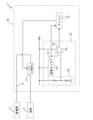
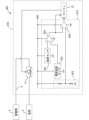
- First Embodiment 1 shows a vehicle 1 equipped with an abnormality determination device 10.
- the vehicle 1 includes a power storage unit 2, a load 3, and a power path 4.
- the power storage unit 2 is configured as, for example, a battery.
- the battery is, for example, a lead battery, a lithium ion battery, or the like.
- the load 3 is a load that can operate when the vehicle 1 is parked.
- the power path 4 is provided between the power storage unit 2 and the load 3.
- the power path 4 is a path that supplies power from the power storage unit 2 to the load 3.
- the vehicle 1 is in a started state when the start switch is on, and in a parked state when the start switch is off.
- the start switch may be an ignition switch, a power switch, or the like.
- the vehicle 1 When the vehicle 1 is in a parked state, it can supply dark current from the power storage unit 2 to the load 3 via the power path 4.
- the abnormality determination device 10 includes a relay 11, an abnormality detection unit 12, and a microcomputer 13 (hereinafter also referred to as MCU 13).
- the relay 11 corresponds to an example of an object to be judged.
- the relay 11 is provided in the power path 4.
- the relay 11 may be a mechanical relay having contacts, or may be a relay constituted by a semiconductor switching element.
- the relay 11 is of a normally-on type.
- the relay 11 is turned on when an on signal (in this embodiment, a low-level signal) is given, and is turned off when an off signal (in this embodiment, a high-level signal) is given.
- an on signal in this embodiment, a low-level signal
- an off signal in this embodiment, a high-level signal
- the abnormality detection unit 12 operates based on power from the power storage unit 2.
- the abnormality detection unit 12 detects that the relay 11 is in a first abnormal state and outputs a detection signal.
- the abnormality detection unit 12 determines that the relay 11 is in the first abnormal state when the temperature of the relay 11 exceeds a first threshold value.
- the abnormality detection unit 12 has a temperature sensor 21, a reference voltage generation circuit 22, and a comparison unit 23.
- the temperature sensor 21 is configured, for example, by a thermistor.
- the temperature sensor 21 detects the temperature of the relay 11 and outputs a signal indicating the detection value.
- the reference voltage generation circuit 22 generates and outputs a voltage corresponding to a first threshold value.
- the comparison unit 23 is configured, for example, as a comparator.
- the output value from the temperature sensor 21 is input to a non-inverting input terminal of the comparison unit 23.
- the output value from the reference voltage generation circuit 22 is input to an inverting input terminal of the comparison unit 23. If the output value from the temperature sensor 21 is greater than the output value from the reference voltage generation circuit 22, the comparison unit 23 outputs a detection signal (specifically, a high-level signal). If the output value from the temperature sensor 21 is smaller than the output value from the reference voltage generation circuit 22, the comparison unit 23 outputs a non-detection signal (specifically, a low-level signal).
- the abnormality detection unit 12 detects the first abnormal state based on the detection value of the temperature sensor 21. Specifically, the abnormality detection unit 12 determines whether or not the temperature of the relay 11 has exceeded a first threshold value. If the abnormality detection unit 12 determines that the temperature of the relay 11 has exceeded the first threshold value, it determines that the first abnormal state has occurred, and outputs a detection signal to the microcomputer 13. If the abnormality detection unit 12 determines that the temperature of the relay 11 has not exceeded the first threshold value, it determines that the first abnormal state has not occurred, and outputs a non-detection signal to the microcomputer 13.
- the microcomputer 13 includes a CPU, memory (e.g., ROM, RAM, flash memory, etc.), etc.
- the microcomputer 13 switches between an active state and a sleep state.
- the sleep state is a state in which power consumption is less than the active state.
- the microcomputer 13 goes into the sleep state when the vehicle 1 is in a parked state, and goes into the active state when the vehicle 1 is in a started state.
- the microcomputer 13 is configured to receive an on/off signal indicating the on/off state of the start switch, and determines whether the vehicle 1 is in a started state or a parked state based on the on/off signal.
- the microcomputer 13 In the activated state, the microcomputer 13 performs a determination process to determine whether the relay 11 is in the second abnormal state. When a detection signal is input in the sleep state, the microcomputer 13 switches to the activated state and performs the above determination process.
- the detection value of the temperature sensor 21 is input to the microcomputer 13.
- the microcomputer 13 determines whether or not the second abnormal state exists based on the detection value of the temperature sensor 21. Specifically, the microcomputer 13 determines that the second abnormal state exists when the temperature of the relay 11 exceeds a second threshold value.
- the second threshold value is a value greater than the first threshold value.
- the microcomputer 13 may immediately determine that the second abnormal state exists when the temperature of the relay 11 exceeds the second threshold value, or may determine that the second abnormal state exists when the state in which the temperature of the relay 11 exceeds the second threshold value continues for a predetermined time.
- the microcomputer 13 determines that the second abnormal state exists, it outputs an off signal (high level signal) to switch the relay 11 to the off state. This cuts off the power supply from the storage unit 2 to the load 3.
- step S11 the microcomputer 13 determines whether or not a detection signal has been input.
- the microcomputer 13 remains in a standby state until a detection signal is input.
- step S13 the microcomputer 13 determines whether or not a second abnormal state has occurred.
- the microcontroller 13 determines in step S14 whether or not the sleep condition is satisfied.
- the sleep condition includes, for example, the temperature of the relay 11 being lower than the third threshold value.
- the sleep condition is, for example, that the temperature of the relay 11 remains lower than the third threshold value for a predetermined period of time.
- the third threshold value may be the same value as the first threshold value, or may be a value lower than the first threshold value.
- the microcomputer 13 repeats the processing of steps S13 and S14 until it determines that the second abnormal state exists or that the sleep condition exists. If the microcomputer 13 determines that the sleep condition exists, it goes into a sleep state in step S15 and returns to step S11. If the microcomputer 13 determines that the second abnormal state exists, it switches the relay 11 to the off state in step S16. The microcomputer 13 then ends the processing shown in FIG. 2.
- the abnormality determination device 10 can reduce power consumption by putting the microcomputer 13 into a sleep state when the vehicle 1 is in a parked state. Furthermore, when the abnormality detection unit 12 detects that the relay 11 is in the first abnormal state, the abnormality determination device 10 can switch the microcomputer 13 into an active state and have it perform a determination process. Therefore, the abnormality determination device 10 can efficiently perform abnormality detection by the microcomputer 13 while reducing power consumption when the vehicle 1 is in a parked state.
- the abnormality determination device 10 can share the same temperature sensor 21 for detecting the first abnormal state and determining the second abnormal state.
- the abnormality determination device 10 can easily detect the first abnormal state by the abnormality detection unit 12 when the temperature of the relay 11 exceeds the second threshold value that is higher than the first threshold value. Therefore, when the temperature of the relay 11 exceeds the second threshold value, the abnormality determination device 10 can more reliably start up the microcomputer 13 and determine that the second abnormal state has occurred.
- the abnormality determination device 10 can cut off the power supply from the power storage unit 2 to the load 3 by the relay 11. Furthermore, because the relay 11 is of a normally-on type, the abnormality determination device 10 can reduce the power consumption required to maintain the relay 11 in the on state when power is being supplied from the power storage unit 2 to the load 3.
- the abnormality detection unit is a thermostat 212.
- the same components as those in the first embodiment are denoted by the same reference numerals, and detailed description thereof will be omitted.
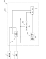
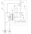
- FIG. 3 shows a vehicle 201 equipped with an abnormality determination device 210 according to the second embodiment.
- the vehicle 201 includes a power storage unit 2, a load 3, and a power line 4.
- the abnormality determination device 210 includes a relay 11, a thermostat 212, a microcontroller temperature sensor 30, and a microcontroller 13.
- the thermostat 212 corresponds to an example of an abnormality detection unit.
- the thermostat 212 detects that the relay 11 is in a first abnormal state and outputs a detection signal.
- the thermostat 212 determines that the relay 11 is in the first abnormal state and outputs a detection signal to the microcomputer 13.
- the microcomputer temperature sensor 30 is composed of, for example, a thermistor.
- the microcomputer temperature sensor 30 detects the temperature of the relay 11 and outputs a signal indicating the detected value to the microcomputer 13.
- the microcomputer 13 determines whether or not the second abnormal state exists based on the temperature detected by the microcomputer temperature sensor 30.
- the other operations of the microcomputer 13 are the same as those in the first embodiment.
- the abnormality detection unit is configured by the thermostat 212, so the configuration of the abnormality detection unit can be simplified.
- FIG. 4 shows a vehicle 301 equipped with an abnormality determination device 310 according to the third embodiment.
- the vehicle 301 includes a power storage unit 2, a load 3, and a power line 4.
- the abnormality determination device 310 includes a relay 11, an abnormality detection unit 12, a microcontroller temperature sensor 330, and a microcontroller 13.
- the microcomputer temperature sensor 330 is a sensor different from the temperature sensor 21 that the abnormality detection unit 12 has.
- the microcomputer temperature sensor 330 detects the temperature of the relay 11 with higher power consumption than the temperature sensor 21.
- the microcomputer temperature sensor 330 detects the temperature of the relay 11 with higher accuracy than the temperature sensor 21.
- the abnormality detection unit 12 detects that a first abnormal state exists based on the detection value of the temperature sensor 21.
- the operation of the abnormality detection unit 12 is the same as in the first embodiment.
- the microcomputer 13 determines whether or not the second abnormal state exists based on the detection value of the microcomputer temperature sensor 330.
- the other operations of the microcomputer 13 are the same as those in the first embodiment.
- the abnormality determination device 310 of the third embodiment can reduce the power consumption required for the abnormality detection unit 12 to detect the first abnormal state. Furthermore, the abnormality determination device 310 can determine the second abnormal state based on the detection value of the highly accurate microcomputer temperature sensor 330, and therefore can determine the second abnormal state with high accuracy.
- the first abnormal state and the second abnormal state are determined based on the difference between the temperature of the relay 11 and the environmental temperature at a position away from the relay 11.
- the same components as those in the first embodiment are denoted by the same reference numerals, and detailed description thereof will be omitted.
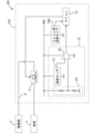
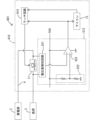
- FIG. 5 shows a vehicle 401 equipped with an abnormality determination device 410 according to the fourth embodiment.
- the vehicle 401 includes a power storage unit 2, a load 3, and a power line 4.
- the abnormality determination device 410 includes a relay 11, an abnormality detection unit 412, and a microcomputer 13.
- the abnormality detection unit 412 operates based on power from the power storage unit 2.
- the abnormality detection unit 412 detects that the relay 11 is in a first abnormal state and outputs a detection signal.
- the abnormality detection unit 412 has a temperature sensor 421, an environmental temperature sensor 422, a reference voltage generation circuit 423, a first comparison unit 424, and a second comparison unit 425. When the difference between the temperature of the relay 11 and the environmental temperature at a position away from the relay 11 exceeds a first threshold, the abnormality detection unit 412 determines that the first abnormal state has occurred and outputs a detection signal.
- the temperature sensor 421 is, for example, a thermistor.
- the temperature sensor 421 detects the temperature of the relay 11 and outputs a signal indicating the detected value.
- the environmental temperature sensor 422 is composed of, for example, a thermistor.
- the environmental temperature sensor 422 detects the environmental temperature at a position away from the relay 11 and outputs a signal indicating the detected value.
- the environmental temperature sensor 422 detects the environmental temperature at a position where the influence of heat generated by the relay 11 is small.
- the reference voltage generation circuit 423 generates and outputs a voltage equivalent to the first threshold value.
- the first comparison unit 424 is configured, for example, as a differential amplifier circuit.
- the output value from the temperature sensor 421 is input to the non-inverting input terminal of the first comparison unit 424.
- the output value from the environmental temperature sensor 422 is input to the inverting input terminal of the first comparison unit 424.
- the first comparison unit 424 outputs a voltage corresponding to the difference between the output value from the temperature sensor 421 and the output value from the reference voltage generation circuit 423. In other words, the first comparison unit 424 outputs the difference between the temperature of the relay 11 and the environmental temperature at a position away from the relay 11.
- the first comparison unit 424 outputs a value obtained by subtracting the environmental temperature from the temperature of the relay 11.
- the second comparison unit 425 is configured, for example, as a comparator.
- the output value from the first comparison unit 424 is input to a non-inverting input terminal of the second comparison unit 425.
- the output value from the reference voltage generation circuit 423 is input to an inverting input terminal of the second comparison unit 425. If the output value from the first comparison unit 424 is greater than the output value from the reference voltage generation circuit 423, the second comparison unit 425 outputs a detection signal (specifically, a high-level signal). If the output value from the first comparison unit 424 is less than the output value from the reference voltage generation circuit 423, the second comparison unit 425 outputs a non-detection signal (specifically, a low-level signal).
- the abnormality detection unit 412 determines whether the difference between the temperature of the relay 11 and the environmental temperature at a position away from the relay 11 exceeds a first threshold value. If the abnormality detection unit 412 determines that the difference between the temperature of the relay 11 and the environmental temperature exceeds the first threshold value, it determines that a first abnormal state exists, and outputs a detection signal to the microcontroller 13. If the abnormality detection unit 412 determines that the difference between the temperature of the relay 11 and the environmental temperature does not exceed the first threshold value, it determines that a first abnormal state does not exist, and outputs a non-detection signal to the microcontroller 13.
- the output value from the first comparison unit 424 (i.e., the difference between the temperature of the relay 11 and the environmental temperature) is input to the microcomputer 13.
- the microcomputer 13 determines whether or not the second abnormal state exists based on the difference between the temperature of the relay 11 and the environmental temperature. Specifically, the microcomputer 13 determines that the second abnormal state exists when the difference between the temperature of the relay 11 and the environmental temperature exceeds a second threshold value.
- the second threshold value is a value greater than the first threshold value.
- the microcomputer 13 may immediately determine that the second abnormal state exists when the difference between the temperature of the relay 11 and the environmental temperature exceeds the second threshold value, or may determine that the second abnormal state exists when the state in which the difference between the temperature of the relay 11 and the environmental temperature exceeds the second threshold value continues for a predetermined time.
- the microcomputer 13 determines that the second abnormal state exists, it outputs an off signal (high level signal) to switch the relay 11 to the off state. This cuts off the power supply from the power storage unit 2 to the load 3.
- the other operations of the microcomputer 13 are the same as those in the first embodiment.
- the abnormality determination device 410 of the fourth embodiment even if the detection accuracy by the abnormality detection unit 412 is low, when the difference between the temperature of the relay 11 and the ambient temperature exceeds the second threshold value that is greater than the first threshold value, the abnormality determination device 410 can more reliably start up the microcomputer 13 and determine that the second abnormality state exists when the difference between the temperature of the relay 11 and the ambient temperature exceeds the second threshold value.
- FIG. 6 shows a vehicle 501 equipped with an abnormality determination device 510 according to the fifth embodiment.
- the vehicle 501 includes a power storage unit 2, a load 3, and a power line 4.
- the abnormality determination device 510 includes a relay 11, an abnormality detection unit 512, and a microcomputer 13.
- the relay 11 is a mechanical relay having contacts.
- the abnormality detection unit 512 operates based on the power from the power storage unit 2.
- the power path 4 corresponds to an example of an object to be determined.
- the abnormality detection unit 512 determines that a first abnormal state exists when the current flowing through the power path 4 exceeds a first threshold value.
- the abnormality detection unit 512 has a potential difference detection circuit 521, a reference voltage generation circuit 522, and a comparison unit 523.
- the potential difference detection circuit 521 detects and outputs the potential difference between both ends of the relay 11. In other words, the potential difference detection circuit 521 detects the current flowing through the relay 11 and outputs a value indicating the current flowing through the relay 11.
- the potential difference detection circuit 521 is configured, for example, by a differential amplifier circuit.
- the reference voltage generation circuit 522 generates and outputs a voltage equivalent to the first threshold value.
- the comparison unit 523 is configured, for example, as a comparator.
- the output value from the potential difference detection circuit 521 is input to the non-inverting input terminal of the comparison unit 523.
- the output value from the reference voltage generation circuit 522 is input to the inverting input terminal of the comparison unit 523. If the output value from the potential difference detection circuit 521 is greater than the output value from the reference voltage generation circuit 522, the comparison unit 523 outputs a detection signal (specifically, a high-level signal). If the output value from the potential difference detection circuit 521 is less than the output value from the reference voltage generation circuit 522, the comparison unit 523 outputs a non-detection signal (specifically, a low-level signal).
- the abnormality detection unit 512 determines whether or not the current flowing through the relay 11 has exceeded the first threshold. If the abnormality detection unit 512 determines that the current flowing through the relay 11 has exceeded the first threshold, it determines that a first abnormal state has occurred, and outputs a detection signal to the microcontroller 13. If the abnormality detection unit 512 determines that the current flowing through the relay 11 has not exceeded the first threshold, it determines that a first abnormal state has not occurred, and outputs a non-detection signal to the microcontroller 13.
- the output value from the potential difference detection circuit 521 (i.e., a value indicating the current flowing through the relay 11) is input to the microcomputer 13.
- the microcomputer 13 determines that the second abnormal state exists when the current flowing through the relay 11 exceeds the second threshold.
- the second threshold is a value greater than the first threshold.
- the microcomputer 13 may immediately determine that the second abnormal state exists when the current flowing through the relay 11 exceeds the second threshold, or may determine that the second abnormal state exists when the state in which the current flowing through the relay 11 exceeds the second threshold continues for a predetermined time.
- the microcomputer 13 determines that the second abnormal state exists, it outputs an off signal (high level signal) to switch the relay 11 to the off state. This cuts off the power supply from the storage unit 2 to the load 3.
- the other operations of the microcomputer 13 are the same as those in the first embodiment.
- the abnormality determination device 510 can easily detect the first abnormal state by the abnormality detection unit 512 when the current flowing through the power path 4 exceeds the second threshold value that is greater than the first threshold value. Therefore, when the current flowing through the power path 4 exceeds the second threshold value, the abnormality determination device 510 can more reliably start up the microcomputer 13 and determine that the second abnormal state has occurred.
- the relay 11 is switched to the OFF state when the first abnormal state is detected, and the relay 11 is returned to the ON state when it is determined that the second abnormal state does not exist.
- the same components as those in the fifth embodiment are denoted by the same reference numerals, and detailed description thereof will be omitted.
- FIG. 7 shows a vehicle 601 equipped with an abnormality determination device 610 according to the sixth embodiment.
- the vehicle 601 includes a power storage unit 2, a load 3, and a power line 4.
- the abnormality determination device 610 includes a relay 11, an abnormality detection unit 512, a microcomputer 13, and a latch circuit 614.
- the latch circuit 614 selectively receives a detection signal and a non-detection signal output from the comparison unit 523 of the abnormality detection unit 512. When a detection signal is input, the latch circuit 614 switches the relay 11 to the off state. The latch circuit 614 maintains the relay 11 in the off state even after the detection signal is no longer input. The latch circuit 614 maintains the relay 11 in the off state until a release signal is input from the microcomputer 13. When a release signal is input, the latch circuit 614 returns the relay 11 to the on state.
- the microcomputer 13 determines whether or not the second abnormal state exists. In this embodiment, the microcomputer 13 determines that the second abnormal state exists when the number of times the device is started in response to the input of the detection signal reaches a predetermined upper limit, and determines that the second abnormal state does not exist when the upper limit has not been reached. When the microcomputer 13 determines that the second abnormal state does not exist, it outputs a release signal to the latch circuit 614, thereby returning the relay 11 to the on state.
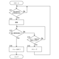
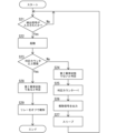
- step S21 the microcomputer 13 determines whether or not a detection signal has been input.
- the microcomputer 13 remains in a standby state until a detection signal is input.
- step S13 the microcomputer 13 determines whether or not the second abnormal state is occurring. Specifically, the microcomputer 13 determines whether or not the number in the determination counter is equal to or greater than the upper limit. The initial value of the determination counter is 0. Therefore, initially, the microcomputer 13 determines that the number in the determination counter is not equal to or greater than the upper limit. Then, in step S24, the microcomputer 13 determines that the second abnormal state is not occurring, and in step S25, the microcomputer 13 increments the determination counter by 1. The determination counter is incremented by 1 each time the microcomputer 13 is activated due to input of a detection signal and determines that the second abnormal state is not occurring.
- step S26 the microcomputer 13 outputs a release signal to the latch circuit 614, and in step S27, goes into a sleep state. After that, the microcomputer 13 returns to step S21.
- the microcomputer 13 repeats the process of steps S21 to S27, and when it determines in step S23 that the number in the determination counter is equal to or greater than the upper limit, it determines in step S28 that a second abnormal state exists.
- step S29 the microcomputer 13 maintains a state in which a release signal is not output, thereby maintaining the relay 11 in the off state. The microcomputer 13 then ends the process shown in FIG. 8.
- the microcomputer 13 may reset the number of judgment counters to 0 when a predetermined initialization condition is met. For example, when the number of judgment counters is 1 or more, the microcomputer 13 may be configured to wake up every time a predetermined time has elapsed after the sleep state even if a detection signal is not input, and may reset the number of judgment counters to 0 when the microcomputer 13 has been started a predetermined number of times without a detection signal being input. Alternatively, when the number of judgment counters is 1 or more, the microcomputer 13 may operate an RTC (Real Time Clock) in the sleep state, and may reset the number of judgment counters to 0 when a predetermined time has elapsed without a detection signal being input.
- RTC Real Time Clock
- the microcomputer 13 may be configured to wake up every time a predetermined time has elapsed after the sleep state even if a detection signal is not input, and may reset the number of judgment counters to 0 when the microcomputer 13 has been started in response to the passage of the predetermined time.
- the on-resistance of the relay 11 is used to detect the current flowing through the relay 11, but the current flowing through the relay 11 may be detected by another method.
- a shunt resistor may be provided in the power path 4, and the potential difference across the shunt resistor may be detected by the potential difference detection circuit 521.
- the current flowing through the relay 11 may be detected by a magnetic sensor such as a Hall element.
Landscapes
- Engineering & Computer Science (AREA)
- Mechanical Engineering (AREA)
- Protection Of Static Devices (AREA)
Abstract
L'invention concerne un dispositif de détermination d'anomalie (10) pourvu d'une unité de détection d'anomalie (12) et d'un micro-ordinateur (13). L'unité de détection d'anomalie (12) détecte qu'une cible de détermination (par exemple, un relais (11)) disposée dans un véhicule (1) est dans un premier état anormal, et délivre un signal de détection. Le micro-ordinateur (13) effectue, dans un état de démarrage, un traitement de détermination pour déterminer si la cible de détermination est dans un second état anormal ou non. Le micro-ordinateur (13) entre dans un état de veille lorsque le véhicule (1) est dans un état de stationnement, commute vers l'état de démarrage lorsque le signal de détection est entré dans l'état de veille, et effectue le traitement de détermination.
Priority Applications (1)
| Application Number | Priority Date | Filing Date | Title |
|---|---|---|---|
| PCT/JP2023/021202 WO2024252572A1 (fr) | 2023-06-07 | 2023-06-07 | Dispositif de détermination d'anomalie |
Applications Claiming Priority (1)
| Application Number | Priority Date | Filing Date | Title |
|---|---|---|---|
| PCT/JP2023/021202 WO2024252572A1 (fr) | 2023-06-07 | 2023-06-07 | Dispositif de détermination d'anomalie |
Publications (1)
| Publication Number | Publication Date |
|---|---|
| WO2024252572A1 true WO2024252572A1 (fr) | 2024-12-12 |
Family
ID=93795379
Family Applications (1)
| Application Number | Title | Priority Date | Filing Date |
|---|---|---|---|
| PCT/JP2023/021202 Ceased WO2024252572A1 (fr) | 2023-06-07 | 2023-06-07 | Dispositif de détermination d'anomalie |
Country Status (1)
| Country | Link |
|---|---|
| WO (1) | WO2024252572A1 (fr) |
Citations (3)
| Publication number | Priority date | Publication date | Assignee | Title |
|---|---|---|---|---|
| JP2010183822A (ja) * | 2009-01-07 | 2010-08-19 | Autonetworks Technologies Ltd | 電力供給制御装置 |
| JP2015042526A (ja) * | 2013-08-26 | 2015-03-05 | 株式会社デンソー | 電子制御装置 |
| JP2022063007A (ja) * | 2020-10-09 | 2022-04-21 | 日立Astemo株式会社 | 車載用電池制御装置 |
-
2023
- 2023-06-07 WO PCT/JP2023/021202 patent/WO2024252572A1/fr not_active Ceased
Patent Citations (3)
| Publication number | Priority date | Publication date | Assignee | Title |
|---|---|---|---|---|
| JP2010183822A (ja) * | 2009-01-07 | 2010-08-19 | Autonetworks Technologies Ltd | 電力供給制御装置 |
| JP2015042526A (ja) * | 2013-08-26 | 2015-03-05 | 株式会社デンソー | 電子制御装置 |
| JP2022063007A (ja) * | 2020-10-09 | 2022-04-21 | 日立Astemo株式会社 | 車載用電池制御装置 |
Similar Documents
| Publication | Publication Date | Title |
|---|---|---|
| EP1950398B1 (fr) | Dispositif de commande électronique | |
| JP4345845B2 (ja) | 電源装置 | |
| JP4807058B2 (ja) | 車両用電源装置 | |
| US11662789B2 (en) | Power supply circuit with switch for connection of a DC power supply to a power supply unit based on sensed temperature | |
| JP2007230398A (ja) | バッテリ監視装置及びバッテリ監視方法 | |
| US7305283B2 (en) | On-vehicle electronic control device | |
| JP6045984B2 (ja) | 二次電池状態検知装置 | |
| CN110962774B (zh) | 电源监测装置、电源控制系统以及电源监测方法 | |
| WO2024252572A1 (fr) | Dispositif de détermination d'anomalie | |
| JP4839711B2 (ja) | 電流センサの故障診断装置 | |
| JP2011077673A (ja) | リセット回路 | |
| CN117856156A (zh) | 用于安全关断车辆中的用电器的装置和方法 | |
| JP5566420B2 (ja) | ガス警報器 | |
| JP2008152322A (ja) | ガス警報器 | |
| JP2002014720A5 (fr) | ||
| JP2013108426A (ja) | 内燃機関の始動制御装置 | |
| JP2007336657A (ja) | 電源供給制御装置 | |
| JP2002014720A (ja) | 電子制御装置 | |
| JP2009053891A (ja) | 熱感知器 | |
| JP2003199393A (ja) | モータ駆動制御装置 | |
| KR20170068000A (ko) | 차량용 전원 관리 장치 및 그 제어방법 | |
| JP2007041824A (ja) | 電子制御ユニットのリセット回路 | |
| JP5082368B2 (ja) | 電池状態検知システム | |
| US12080112B2 (en) | Electronic control device and diagnosis method of electronic control device | |
| JP4518261B2 (ja) | 車両のバッテリ電流検出装置 |
Legal Events
| Date | Code | Title | Description |
|---|---|---|---|
| 121 | Ep: the epo has been informed by wipo that ep was designated in this application |
Ref document number: 23940674 Country of ref document: EP Kind code of ref document: A1 |
|
| NENP | Non-entry into the national phase |
Ref country code: DE |