WO2024252583A1 - Simulation device and computer-readable storage medium - Google Patents
Simulation device and computer-readable storage medium Download PDFInfo
- Publication number
- WO2024252583A1 WO2024252583A1 PCT/JP2023/021229 JP2023021229W WO2024252583A1 WO 2024252583 A1 WO2024252583 A1 WO 2024252583A1 JP 2023021229 W JP2023021229 W JP 2023021229W WO 2024252583 A1 WO2024252583 A1 WO 2024252583A1
- Authority
- WO
- WIPO (PCT)
- Prior art keywords
- point sequence
- sequence data
- data
- machining
- simulation
- Prior art date
- Legal status (The legal status is an assumption and is not a legal conclusion. Google has not performed a legal analysis and makes no representation as to the accuracy of the status listed.)
- Ceased
Links
Images


Classifications
-
- G—PHYSICS
- G05—CONTROLLING; REGULATING
- G05B—CONTROL OR REGULATING SYSTEMS IN GENERAL; FUNCTIONAL ELEMENTS OF SUCH SYSTEMS; MONITORING OR TESTING ARRANGEMENTS FOR SUCH SYSTEMS OR ELEMENTS
- G05B19/00—Program-control systems
- G05B19/02—Program-control systems electric
- G05B19/18—Numerical control [NC], i.e. automatically operating machines, in particular machine tools, e.g. in a manufacturing environment, so as to execute positioning, movement or co-ordinated operations by means of program data in numerical form
- G05B19/406—Numerical control [NC], i.e. automatically operating machines, in particular machine tools, e.g. in a manufacturing environment, so as to execute positioning, movement or co-ordinated operations by means of program data in numerical form characterised by monitoring or safety
- G05B19/4069—Simulating machining process on screen
Definitions
- the present disclosure relates to a simulation device and a computer-readable storage medium.
- simulation devices there are numerical control devices equipped with a simulation function.
- information processing devices such as PCs (personal computers) equipped with a configuration that simulates a numerical control device.
- simulation devices analyze machining programs, generate commands, and create simulation images based on the generated commands.
- the number of points where the required machining accuracy is low can be fewer than that of fine parts. In the field of creating simulation images of machine tools, it is desirable to reduce the amount of data used in the simulation.
- the simulation device includes a program analysis unit that analyzes a machining program, a point sequence data acquisition unit that acquires point sequence data in which tool positions are arranged in chronological order based on the analysis results of the machining program, a data selection unit that selects point sequence data to be used in creating a simulation image based on modal data at the time the point sequence data was acquired, and a simulation unit that uses the selected point sequence data to create a simulation image that visually represents the cutting process.
- FIG. 1 is a block diagram of a numerical control device according to an embodiment of the present invention
- 13 is an example of a display screen for registering the correspondence between a program number and a machining state.
- 11 is a table showing the correspondence between tool numbers and tool diameters.
- FIG. 13 is a schematic diagram showing a configuration of point sequence data to which a machining state has been added.
- FIG. 13 is a schematic diagram showing a configuration of point sequence data to which a tool radius has been added.
- FIG. 13 is an explanatory diagram of deviation of point sequence data.
- FIG. 11 is an explanatory diagram of data selection using deviations in point sequence data.
- FIG. 2 is a hardware configuration diagram of a numerical control device.
- the simulation device can also be applied to an information processing device that simulates the numerical control device 100.
- the simulation device has a function of analyzing a machining program and creating tool position data, similar to the numerical control device 100.
- 1 is a block diagram showing the configuration of a numerical control device 100.
- the numerical control device 100 includes a program analysis unit 11, an interpolation unit 12, a command unit 13, a motor control unit 14, a point sequence data acquisition unit 15, a data selection unit 16, a machining state addition unit 17, and a simulation unit 18.
- the program analysis unit 11 analyzes the machining program and calculates the tool path, tool speed, and the like.
- the interpolation unit 12 calculates a command value per command cycle. For example, in position control, the command value is a movement amount of a motor divided into minute time units.
- the command unit 13 outputs a control pulse corresponding to the command value calculated by the interpolation unit 12 to the motor control unit.
- the motor control unit 14 controls the servo motor and the spindle motor.
- the servo motor and the spindle motor are equipped with an encoder that detects the amount of rotation of the motor.
- the point sequence data acquisition unit 15 acquires point sequence data.
- Point sequence data is a time series of changes in the position and posture of the tool tip.
- Point sequence data that does not involve actual machining is data in which tool positions are arranged in time series based on control commands that perform servo control, calculated from the machining program.
- Point sequence data that involves actual machining is the changes in the actual position and posture of the tool tip that are fed back from the motor control unit 14.
- the machining state addition unit 17 acquires modal data at the time when the point sequence data is acquired.
- the modal data is data that represents the machining state of the machining program.
- the modal data is obtained directly as a result of program analysis.
- the machining state can be determined from the modal data.
- the modal data includes the program number, the tool number, and the enable/disable of the compensation function. In this embodiment, for convenience, the modal data includes comments on the machining program.
- the machining state adding unit 17 judges the machining state from the modal data, and adds the machining state (or modal data representing the machining state) to the point sequence data.
- the machining state is data representing machining accuracy. Machining states include "rough cutting", "semi-finishing", and "finishing".
- One example of a method for judging the machining state is a method using a program number.
- the correspondence between the program number and the machining state is registered in advance.
- the "subprogram number" is treated as modal data. Specifically, the subprogram number "1000" is associated with the machining state “rough cutting”, the subprogram number "1001” is associated with the machining state “rough cutting”, the subprogram number "1002” is associated with the machining state “semi-finishing”, and the subprogram number "1003" is associated with the machining state "finishing".
- modal data that indicates the machining state is the tool number.
- the tool number indicates the machining state.
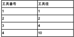
- the machining state adding unit 17 obtains a correspondence table between tool numbers and tool diameters. In the table of Fig. 3, tool number "1" corresponds to tool diameter "1", tool number "2” corresponds to tool diameter "2", tool number "3" corresponds to tool diameter "4", and tool number "4" corresponds to tool diameter "10".
- the correspondence between tool numbers and tool diameters can be obtained from a tool management system or the like.
- the tool management system is an existing technology.
- the tool management system manages information such as machining programs and tool lists.
- the machining state adding unit 17 adds the machining state (including modal data serving as a criterion for determining the machining state) to the point sequence data acquired by the point sequence data acquiring unit 15 .
- the point sequence data is time series data in which time and coordinates are associated.
- the "machining state" of the point sequence data is added to the "time” and "value” of the point sequence data.
- the point sequence data from time “0" to less than “50” corresponds to the machining state "fast forward”
- the point sequence data from time “50” to less than “60” corresponds to the machining state "rough cutting”
- the point sequence data from time “60” to less than "1000” corresponds to the machining state "fast forward”
- the point sequence data from time "1000” onwards corresponds to the machining state "finishing”.
- the tool diameter can be used as data to represent the machining state.
- the "tool diameter” is added to the "time” of the point sequence data and the "value" of the point sequence data.
- the tool diameter for rapid traverse is set to "-1.”
- a tool diameter of "-1" means that no cutting is performed.
- the data selection unit 16 selects point sequence data to be used in the simulation image.
- a tolerance value is used to select the data.
- the tolerance value will be explained with reference to FIG. 6.
- the tolerance value means the allowable deviation of three consecutive point sequence data. The deviation is calculated by selecting point P2 and three points (P1, P2, P3) before and after it, and connecting the previous and next points with lines from start point P1 to end point P3. Then, the distance between point P2 and the line segment connecting P1 and P3 is calculated. If this distance (called the deviation) is greater than the tolerance value, it is determined that the deviation of point P2 exceeds the allowable value.
- step 1 the starting point P1 of the point sequence data is determined.
- the black circle point is the starting point P1.
- three points (P1, P2, P3) starting from the black circle point P1 are selected, and the deviation of P2 is calculated.
- P2 is removed from the point sequence data.
- step 3 three points (P1, P3, P4) excluding P2 are selected.
- the data selection unit calculates the deviation of P3 based on the new three points (P1, P3, P4).
- the deviation of P3 among the new three points (P1, P3, P4) is equal to or greater than the tolerance value.
- the data selection unit 16 sets P3 as the new starting point.
- step S5 the data selection unit 16 selects three points (P3, P4, P5) starting from P3, and finds the deviation of P4. The deviation of P4 is equal to or greater than the tolerance value.
- step S6 the data selection unit 16 sets P4 as the new starting point.
- step 7 the data selection unit 16 selects three points (P4, P5, P6) starting from P4, and finds the deviation of P5. Since the deviation of P5 is smaller than the tolerance value, P5 is excluded from the point sequence data, and three new points (P4, P6, P7) starting from P4 are selected. The data selection unit 16 repeats this process to select point sequence data.
- FIG. 8 is a table showing the correspondence between the machining state and the tolerance value.
- the machining state “fast forward” is associated with the selection method "not selected”
- the machining state “finishing” with the tolerance value “T3 ( ⁇ m)” The relationship between the machining state and the tolerance value is T1>T2>T3.
- the tolerance value "T1" for "rough cutting” is smaller than the tolerance value "T2” for “semi-finishing", which is smaller than the tolerance value "T3” for “finishing”.
- the more importance is placed on precision in the machining, the smaller the tolerance value.
- the data selection unit 16 calculates the deviation of the three points, and if the deviation is smaller than the tolerance value "T1 ( ⁇ m)", it excludes the middle point from the point sequence data. On the other hand, if the deviation is equal to or larger than the tolerance value "T1 ( ⁇ m)", it selects the middle point as the point sequence data and sets it as a new starting point.
- the data selection unit 16 calculates the deviation of the three points, and if the deviation is smaller than the tolerance value "T2 ( ⁇ m)", it excludes the middle point from the point sequence data.
- the data selection unit 16 calculates the deviation of the three points, and if the deviation is smaller than the tolerance value "T3 ( ⁇ m)", it excludes the middle point from the point sequence data. On the other hand, if the deviation is equal to or larger than the tolerance value "T3 ( ⁇ m)", it selects the middle point as the point sequence data and sets it as a new starting point.
- the relationship between the machining state and the tolerance value is T1>T2>T3, so for the same point sequence data, the more emphasis is placed on precision in machining such as "finishing," the more point sequence data is used to create the selected simulation image, and the less emphasis is placed on precision in machining such as "rough cutting,” the more point sequence data is used to create the selected simulation image.
- tool diameter and tolerance value Generally, tools with small diameters are used for high-precision machining. Small tolerance values are associated with machining using tools with small diameters.
- the simulation unit 18 stores three-dimensional image data of the tool shape and the workpiece shape.
- the simulation unit 18 moves the three-dimensional image data of the tool along the point sequence data.
- the simulation unit 18 calculates the cutting area of the tool from the three-dimensional image data of the workpiece, removes the cutting area from the workpiece surface, and creates a simulation image that visually represents the cutting process.
- the number of point sequence data processed by the simulation unit 18 varies depending on the tolerance value.
- the tolerance value T3 in "rough cutting” is the highest. In “rough cutting”, it is not necessary to reflect small changes in the point sequence data in the simulation image. In “rough cutting”, small deviations are ignored, so the number of point sequence data to be selected is reduced.
- the tolerance value T2 of "semi-finishing” is smaller than the tolerance value T1 of "rough cutting.”
- Semi-finishing requires higher accuracy than "rough cutting,” but does not require the same high accuracy as “finishing.”
- the tolerance value T3 is the lowest. For “finishing,” which requires high accuracy, even if the change in the point sequence data is small, the point sequence data in which the change occurred is selected and reflected in the simulation image, so that a highly accurate simulation image can be created.
- step S10 is a flow chart for explaining the operation of the numerical control device 100 of this embodiment.
- the operation of the numerical control device 100 differs between (1) a case where actual machining is not performed and (2) a case where actual machining is performed.
- step S10 the program analysis unit 11 analyzes the machining program (step S11), the interpolation unit 12 calculates a command value per command cycle (step S12), and the command unit 13 outputs a control pulse corresponding to the command value calculated by the interpolation unit 12 to the motor control unit 14 (step S13).
- the motor control unit 14 controls the motor of the machine tool according to commands from the command unit 13.
- the motor is provided with a measuring device such as an encoder.
- the point sequence data acquisition unit 15 acquires the amount of motor rotation (corresponding to the amount of movement of the axis) from the motor.
- the point sequence data acquisition unit 15 acquires point sequence data, which is a set of coordinate positions of the tool (the movement path of the tool), based on the amount of motor rotation (step S14).
- step S10 If actual machining is not involved (step S10; No), the program analysis unit 11 generates point sequence data by analyzing the machining program (step S15).
- the point sequence data corresponds to a set of coordinate positions of the tool (the tool's movement path).
- the point sequence data acquisition unit 15 acquires the point sequence data generated by the program analysis unit 11 (step S16).
- the machining state addition unit 17 judges the machining state of the machine tool when the point sequence data was acquired based on the modal data (step S17).
- the machining state includes "rough cutting”, “semi-finishing", “finishing”, etc.
- the machining state is judged using the program number, tool number, tool diameter, machining program comment, etc.
- the machining state adding section 17 adds machining state information (which may be modal data) to the point sequence data acquired by the point sequence data acquiring section 15 (step S18).
- the data selection unit 16 calculates the deviation of the three points from the point sequence data acquired by the point sequence data acquisition unit 15 (step S19).
- the tolerance value which is the allowable deviation value, is determined by the machining state of the machine tool when the point sequence data is acquired.
- the tolerance value in the "rough cutting” machining state is "T1”
- the tolerance value in the "semi-finish” machining state is "T2”
- the tolerance value in the "finish” machining state is "T3”.
- the data selection unit 16 compares the deviation with the tolerance value, and selects points whose deviation is equal to or greater than the tolerance value as point sequence data for creating a simulation image (step S20).
- the change in the point sequence data is small, so the data is excluded from the point sequence data for creating a simulation image. If the deviation of the three points is equal to or greater than the tolerance value, the change in the point sequence data is large, so the middle point of the three points is selected.
- the data selection unit 16 checks whether the final data of the point sequence data has been processed, and if the final data of the point sequence data has not been processed (step S21; No), it proceeds to step S19, selects three points starting from the point selected in step S20, and calculates the deviation. If the final data of the point sequence data has been processed (step S21; Yes), the data selection unit 16 ends the selection of the point sequence data.
- the simulation unit 18 creates a simulation image of the machining using the point sequence data acquired from the data selection unit 16 (step S22).
- the number of point sequence data for creating the simulation image is adjusted according to the machining state and the deviation of the point sequence data. This reduces the memory load and calculation load required for the simulation.
- the types of simulation include a simulation of the surface quality of the cut surface of a workpiece, and a machine simulation that visualizes the movement of a machine when a program is executed using a three-dimensional model.
- Figure 10 is a hardware configuration diagram of the numerical control device 100.
- the numerical control device 100 is equipped with a CPU 111 that controls the numerical control device 100 as a whole, a ROM 112 that records programs and data, and a RAM 113 for temporarily expanding data.
- the CPU 111 reads out the system program recorded in the ROM 112 via the bus and executes the workaround according to the system program.
- the non-volatile memory 114 is backed up by, for example, a battery (not shown), and retains its stored state even when the power supply to the numerical control device 100 is turned off.
- the non-volatile memory 114 stores various data, such as programs read from the external device 120 via the interfaces 115, 118, and 119, and operation inputs input via the input unit 30.
- the non-volatile memory 114 may also store programs and data for executing the numerical control device 100 of this embodiment.
- the display unit 70 displays various data, measurement results, causes of invalid data, and the like.
- the interface 115 is an interface for connecting the numerical control device 100 to an external device 120 such as an adapter. Programs, various parameters, and the like are read from the external device 120.
- the interface 118 is an interface for connecting the numerical control device 100 to a display unit 70 such as a liquid crystal display. The display unit 70 displays various data loaded onto the memory, data obtained as a result of execution of a program, and the like.
- the interface 119 is an interface for connecting the numerical control device 100 to an input unit 30 such as a keyboard, a pointing device, etc. The input unit 30 passes instructions, data, etc. based on operations by an operator to the CPU 111 via the interface 119.
- the simulation device (100) comprises a program analysis unit (11) that analyzes a machining program, a point sequence data acquisition unit (15) that acquires point sequence data in which tool positions are arranged in chronological order based on the analysis results of the machining program, a data selection unit (16) that selects point sequence data to be used for creating a simulation image based on modal data at the time the point sequence data was acquired, and a simulation unit (18) that uses the selected point sequence data to create a simulation image that visually represents the machining process.
- a program analysis unit (11) that analyzes a machining program
- a point sequence data acquisition unit that acquires point sequence data in which tool positions are arranged in chronological order based on the analysis results of the machining program
- a data selection unit (16) that selects point sequence data to be used for creating a simulation image based on modal data at the time the point sequence data was acquired
- a simulation unit (18) that uses the selected point sequence data to create a simulation image that visually represents the machining process.
- the simulation device (100) includes a machining state adding unit (17) that judges the machining state based on the modal data and adds the machining state to the point sequence data, and the data selecting unit (16) selects the point sequence data based on the machining state.
- the machining state is associated with a tolerance value, and the data selection unit (16) calculates a deviation of a point included in the point sequence data from a line segment passing through adjacent points before and after the point, and selects the point sequence data using the tolerance value as a threshold value for the deviation.
- the machining state includes at least one of rough cutting, semi-finishing, and finishing.
- the data selection unit (16) does not select point sequence data in which the machining state is fast forward.
- the tolerance value is smaller as the machining state places greater importance on precision.
- the point sequence data acquisition unit (15) acquires point sequence data in actual machining.
- the point sequence data acquisition unit (15) acquires point sequence data obtained from a control command for controlling a servo motor based on the machining program.
- the modal data is a program number.
- the modal data is a tool number.
- the storage medium (112, 113, 114) stores instructions for causing one or more processors (111) to execute processing to analyze a machining program, acquire point sequence data in which tool positions are arranged in chronological order based on the analysis results of the machining program, select point sequence data to be used for creating a simulation image based on modal data at the time when the point sequence data was acquired, and create a simulation image that visually represents the machining process using the selected point sequence data.
Landscapes
- Engineering & Computer Science (AREA)
- Human Computer Interaction (AREA)
- Manufacturing & Machinery (AREA)
- Physics & Mathematics (AREA)
- General Physics & Mathematics (AREA)
- Automation & Control Theory (AREA)
- Numerical Control (AREA)
Abstract
Description
本開示は、シミュレーション装置、及びコンピュータが読み取り可能な記憶媒体に関する。 The present disclosure relates to a simulation device and a computer-readable storage medium.
従来、シミュレーション機能を備えた数値制御装置が存在する。また、数値制御装置を模擬した構成を備えたPC(パーソナルコンピュータ)などの情報処理装置が存在する。シミュレーション機能を備えたこれらの情報処理装置(以降、シミュレーション装置と呼ぶ)では、加工プログラムを解析し、指令を生成し、生成した指令を基にシミュレーション画像を作成する。 Conventionally, there are numerical control devices equipped with a simulation function. In addition, there are information processing devices such as PCs (personal computers) equipped with a configuration that simulates a numerical control device. These information processing devices equipped with a simulation function (hereafter referred to as simulation devices) analyze machining programs, generate commands, and create simulation images based on the generated commands.
シミュレーションの実行では、一般的に、データの増加が原因となり、計算時間及びメモリ使用量の増大、シミュレーション結果を表示するまでに要する時間の増加という問題が発生する。これらの問題を回避するため、シミュレーションに用いる点を選択する技術が存在する。例えば、特許文献1。
When running a simulation, problems generally occur due to an increase in data, such as increased calculation time, memory usage, and an increase in the time required to display the simulation results. To avoid these problems, there is a technique for selecting the points to be used in the simulation. For example, see
しかしながら、各点をシミュレーションに用いるかどうかを選別するための情報が工具点列しかない場合、十分に点数を減らすことができない。 However, if the only information available for selecting whether or not to use each point in the simulation is the sequence of tool points, it is not possible to reduce the number of points sufficiently.
例えば、ワーク形状の切削過程をシミュレーションする場合、工具がワークに当たらずに移動しているだけの部分はシミュレーションに用いる必要はない。また、要求される加工精度が粗い部分の点は、細かい部分と比較して少なくてよい。
工作機械のシミュレーション画像の作成分野では、シミュレーションに用いるデータを削減することが望まれている。
For example, when simulating the cutting process of a workpiece shape, there is no need to use the parts where the tool is just moving without hitting the workpiece in the simulation. Also, the number of points where the required machining accuracy is low can be fewer than that of fine parts.
In the field of creating simulation images of machine tools, it is desirable to reduce the amount of data used in the simulation.
本開示の一態様であるシミュレーション装置は、加工プログラムを解析するプログラム解析部と、加工プログラムの解析結果に基づき、工具の位置を時系列で並べた点列データを取得する点列データ取得部と、点列データを取得した時点のモーダルデータを基に、シミュレーション画像の作成に用いる点列データを選択するデータ選択部と、選択された点列データを用いて、切削の過程を視覚的に表現するシミュレーション画像を作成するシミュレーション部と、を備える。 The simulation device according to one aspect of the present disclosure includes a program analysis unit that analyzes a machining program, a point sequence data acquisition unit that acquires point sequence data in which tool positions are arranged in chronological order based on the analysis results of the machining program, a data selection unit that selects point sequence data to be used in creating a simulation image based on modal data at the time the point sequence data was acquired, and a simulation unit that uses the selected point sequence data to create a simulation image that visually represents the cutting process.
以下、図面を参照して本実施形態の数値制御装置100について説明する。以下の本実施形態では、シミュレーション装置を適用した数値制御装置100について説明する。シミュレーション装置は、数値制御装置100を模擬する情報処理装置にも適用することができる。シミュレーション装置は、数値制御装置100と同様に加工プログラムを解析して工具位置データを作成する機能を有する。
図1は、数値制御装置100の構成を示すブロック図である。数値制御装置100は、プログラム解析部11、補間部12、指令部13、モータ制御部14、点列データ取得部15、データ選択部16、加工状態付加部17、シミュレーション部18を備える。
Hereinafter, a
1 is a block diagram showing the configuration of a
プログラム解析部11は、加工プログラムを解析し、工具経路、工具速度などを算出する。
補間部12は、指令周期あたりの指令値を算出する。例えば、位置制御において、指令値は、微細な時間単位に分割されたモータの移動量である。
指令部13は、補間部12が算出した指令値に相当する制御パルスをモータ制御部に出力する。
The
The
The
モータ制御部14は、サーボモータ及びスピンドルモータを制御する。サーボモータ及びスピンドルモータには、モータの回転量を検出するエンコーダなどが設けられている。
The
点列データ取得部15は、点列データを取得する。点列データは、工具先端の位置及び姿勢の推移を時系列で並べたものである。点列データには、(1)実加工を伴わない点列データと、(2)実加工を伴う点列データとがある。(1)実加工を伴わない点列データとは、加工プログラムから算出した、サーボ制御を行う制御指令に基づき、工具位置を時系列に並べたデータである。(2)実加工を伴う点列データとは、モータ制御部14からフィードバックした実際の工具先端の位置及び姿勢の推移である。
The point sequence
加工状態付加部17は、点列データを取得した時点のモーダルデータを取得する。モーダルデータとは、加工プログラムの加工状態を表すデータである。モーダルデータは、プログラム解析の結果、直接得られる。加工状態は、モーダルデータから判断できる。モーダルデータには、プログラム番号、工具番号、補正機能の有効/無効などがある。なお、本実施形態では、便宜上、加工プログラムのコメントをモーダルデータに含む。
加工状態付加部17は、モーダルデータから加工状態を判定し、点列データに加工状態(又は加工状態を表すモーダルデータ)を付加する。加工状態は、加工精度を表すデータである。加工状態には、「荒削り」、「中仕上げ」、「仕上げ」などがある。加工状態の判定方法の一例としてプログラム番号を使った方法がある。この方法では、予めプログラム番号と加工状態との対応付けを登録する。図2の例では、「サブプログラム番号」をモーダルデータとして扱う。具体的には、サブプログラム番号「1000」と加工状態「荒削り」、サブプログラム番号「1001」と加工状態「荒削り」、サブプログラム番号「1002」と加工状態「中仕上げ」、サブプログラム番号「1003」と加工状態「仕上げ」が対応づけられている。
The machining
The machining
加工状態を表すモーダルデータの別の例として工具番号がある。工具番号と工具径は一対一対応している。加工精度と工具径には、関連がある。一般に、精度の高い加工では小さい径の工具が用いられる。工具番号は、加工状態を表す。
加工状態付加部17は、工具番号と工具径の対応表を取得する。図3の表では、工具番号「1」と工具径「1」、工具番号「2」と工具径「2」、工具番号「3」と工具径「4」、工具番号「4」と工具径「10」が対応づけられている。工具番号と工具径の対応付けは工具管理システムなどから取得できる。工具管理システムは、既存の技術である。工具管理システムは、加工プログラム、工具リストなどの情報を管理する。
Another example of modal data that indicates the machining state is the tool number. There is a one-to-one correspondence between the tool number and the tool diameter. There is a relationship between machining accuracy and the tool diameter. In general, a tool with a small diameter is used for high-precision machining. The tool number indicates the machining state.
The machining
加工状態付加部17は、点列データ取得部15で取得した点列データに加工状態(加工状態判定の基準となるモーダルデータも含む)を付加する。
点列データは、時刻と座標が関連付けられた時系列データである。図4の表では、点列データの「時刻」と点列データの「値」に、点列データの「加工状態」が付加されている。図4の表では、時刻「0」から「50」未満の点列データと加工状態「早送り」、時刻「50」から「60」未満の点列データと加工状態「荒削り」、時刻「60」から「1000」未満の点列データと加工状態「早送り」、時刻「1000」以降の点列データと加工状態「仕上げ」が対応づけられている。
The machining
The point sequence data is time series data in which time and coordinates are associated. In the table of Fig. 4, the "machining state" of the point sequence data is added to the "time" and "value" of the point sequence data. In the table of Fig. 4, the point sequence data from time "0" to less than "50" corresponds to the machining state "fast forward", the point sequence data from time "50" to less than "60" corresponds to the machining state "rough cutting", the point sequence data from time "60" to less than "1000" corresponds to the machining state "fast forward", and the point sequence data from time "1000" onwards corresponds to the machining state "finishing".
工具径は、加工状態を表現するデータとして使用可能である。図5の表では、点列データの「時刻」と点列データの「値」に、「工具径」が付加されている。なお、早送りの工具径は便宜上「-1」に設定する。工具径「-1」は、切削しないことを意味する。 The tool diameter can be used as data to represent the machining state. In the table in Figure 5, the "tool diameter" is added to the "time" of the point sequence data and the "value" of the point sequence data. For convenience, the tool diameter for rapid traverse is set to "-1." A tool diameter of "-1" means that no cutting is performed.
データ選択部16は、シミュレーション画像に用いる点列データの選択を行う。データの選択には、トレランス値を用いる。図6を参照してトレランス値について説明する。トレランス値とは、連続する3つの点列データのズレの許容値を意味する。ズレの算出方法は、点P2と、その前後の点の3点(P1、P2、P3)を選択し、前後の点を始点P1と終点P3を線で結ぶ。そして、P1とP3を結ぶ線分と点P2との距離を算出する。この距離(ズレとよぶ)がトレランス値よりも大きければ、点P2のズレは許容値を超えると判定する。
The
図7を参照してトレランス値を用いたデータ選択の方法について説明する。なお、図7の斜線部は線分を中心としたトレランス値の範囲を示す。
まず、ステップ1において点列データの始点P1を決める。図7では、黒丸の点が始点P1である。ステップ2では、黒丸の点P1を先頭とした3点(P1、P2、P3)を選択し、P2のズレを算出する。P2のズレとトレランス値とを比較すると、ズレがトレランス値よりも小さい。そのため、P2を点列データから外す。
ステップ3では、P2を除く3点(P1、P3、P4)を選択する。データ選択部は、新たな3点(P1、P3、P4)を基に、P3のズレを算出する。新たな3点(P1、P3、P4)のP3のズレがトレランス値以上である。データ選択部16は、ステップ4において、P3を新たな始点に設定する。
A method of selecting data using a tolerance value will be described with reference to Fig. 7. Note that the shaded area in Fig. 7 indicates the range of tolerance values centered on the line segment.
First, in
In step 3, three points (P1, P3, P4) excluding P2 are selected. The data selection unit calculates the deviation of P3 based on the new three points (P1, P3, P4). The deviation of P3 among the new three points (P1, P3, P4) is equal to or greater than the tolerance value. In
ステップ5において、データ選択部16は、P3を始点とした3点(P3、P4、P5)を選択し、P4のズレを求める。P4のズレはトレランス値以上である。データ選択部16は、ステップS6において、P4を新たな始点に設定する。
In step S5, the
ステップ7において、データ選択部16は、P4を始点とした3点(P4、P5、P6)を選択し、P5のズレを求める。P5のズレはトレランス値よりも小さいので、P5を点列データから除外し、P4を始点とした新たな3点(P4、P6、P7)を選択する。データ選択部16は、この処理を繰り返し、点列データの選択を行う。
In step 7, the
トレランス値は、加工状態に応じて変化する。図8は、加工状態とトレランス値との対応を示す表である。図8の表では、加工状態「早送り」と選択方法「選択しない」、加工状態「荒削り」とトレランス値「T1(μm)」、加工状態「中仕上げ」とトレランス値「T2(μm)」、加工状態「仕上げ」とトレランス値「T3(μm)」が関連づけられている。加工状態とトレランス値との関係は、T1>T2>T3である。すなわち、「荒削り」のトレランス値「T1」は、「中仕上げ」のトレランス値「T2」より小さく、「中仕上げ」のトレランス値「T2」は「仕上げ」のトレランス値「T3」よりも小さい。精度を重視する加工ほどトレランス値は小さくなる。 The tolerance value changes depending on the machining state. Figure 8 is a table showing the correspondence between the machining state and the tolerance value. In the table of Figure 8, the machining state "fast forward" is associated with the selection method "not selected", the machining state "rough cutting" with the tolerance value "T1 (μm)", the machining state "semi-finishing" with the tolerance value "T2 (μm)", and the machining state "finishing" with the tolerance value "T3 (μm)". The relationship between the machining state and the tolerance value is T1>T2>T3. In other words, the tolerance value "T1" for "rough cutting" is smaller than the tolerance value "T2" for "semi-finishing", which is smaller than the tolerance value "T3" for "finishing". The more importance is placed on precision in the machining, the smaller the tolerance value.
加工状態が「早送り」のときは、他の加工状態の場合と異なる。「早送り」では、点列データを選択しない。「早送り」では、加工をしないためである。加工状態が「早送り」のとき、シミュレーション画像の作成に使用される点列データの個数は「0」になる。点列データの個数が少なくなるため、シミュレーション画像の作成に要するメモリ及び演算装置への負荷が軽減される。 When the processing state is "fast forward," it is different from other processing states. In "fast forward," no point sequence data is selected. This is because no processing is performed in "fast forward." When the processing state is "fast forward," the number of point sequence data used to create the simulation image becomes "0." Because the number of point sequence data is reduced, the load on the memory and calculation device required to create the simulation image is reduced.
加工状態が「荒削り」のとき、データ選択部16は、3点のズレを算出し、ズレがトレランス値「T1(μm)」より小さければ、真ん中の点を点列データから除外する。一方、ズレがトレランス値「T1(μm)」以上であれば真ん中の点を点列データとして選択し、新たな始点に設定する。
加工状態が「中仕上げ」のとき、データ選択部16は、3点のズレを算出し、ズレがトレランス値「T2(μm)」より小さければ、真ん中の点を点列データから除外する。一方、ズレがトレランス値「T2(μm)」以上であれば真ん中の点を点列データとして選択し、新たな始点に設定する。
加工状態が「仕上げ」のとき、データ選択部16は、3点のズレを算出し、ズレがトレランス値「T3(μm)」より小さければ、真ん中の点を点列データから除外する。一方、ズレがトレランス値「T3(μm)」以上であれば真ん中の点を点列データとして選択し、新たな始点に設定する。
When the machining state is "rough cutting", the
When the machining state is "semi-finishing", the
When the machining state is "finishing", the
加工状態とトレランス値との関係は、T1>T2>T3であるため、同じ点列データであれば、「仕上げ」のような精度を重視する加工ほど選択するシミュレーション画像の作成に使用する点列データの数が増加し、「荒削り」のような比較的精度を重視しない加工では選択するシミュレーション画像の作成に使用する点列データの数が少なくなる。
また、工具径とトレランス値にも関連がある。一般に、精度の高い加工では小さい径の工具が用いられる。小さい径の工具を使用する加工には、小さいトレランス値を対応付ける。
The relationship between the machining state and the tolerance value is T1>T2>T3, so for the same point sequence data, the more emphasis is placed on precision in machining such as "finishing," the more point sequence data is used to create the selected simulation image, and the less emphasis is placed on precision in machining such as "rough cutting," the more point sequence data is used to create the selected simulation image.
There is also a relationship between tool diameter and tolerance value. Generally, tools with small diameters are used for high-precision machining. Small tolerance values are associated with machining using tools with small diameters.
シミュレーション部18は、工具形状、ワーク形状の3次元画像データなどを記憶する。シミュレーション部18は、工具の3次元画像データを点列データに沿って移動させる。シミュレーション部18は、ワークの3次元画像データから工具の切削領域を演算し、ワーク表面から切削領域を除去し、切削の過程を視覚的に表現するシミュレーション画像を作成する。
The
シミュレーション部18が処理する点列データの個数は、トレランス値によって変化する。本実施の形態では、「荒削り」におけるトレランス値T3が最も高い。「荒削り」では、点列データの小さな変化をシミュレーション画像に反映させる必要はない。「荒削り」では、小さなズレは無視するため、選択する点列データの個数が少なくなる。
「中仕上げ」のトレランス値T2は、「荒削り」のトレランス値T1よりも小さい。「中仕上げ」では、「荒削り」よりも高い精度が求められるが、「仕上げ」と同等の高い精度は求められない。
高い精度が要求される「仕上げ」は、トレランス値T3が最も低い。高い精度が要求される「仕上げ」では、点列データの小さな変化であっても、変化が生じた点列データを選択し、シミュレーション画像に反映させるため、精度の高いシミュレーション画像を作成することができる。
The number of point sequence data processed by the
The tolerance value T2 of "semi-finishing" is smaller than the tolerance value T1 of "rough cutting.""Semi-finishing" requires higher accuracy than "rough cutting," but does not require the same high accuracy as "finishing."
For "finishing," which requires high accuracy, the tolerance value T3 is the lowest. For "finishing," which requires high accuracy, even if the change in the point sequence data is small, the point sequence data in which the change occurred is selected and reflected in the simulation image, so that a highly accurate simulation image can be created.
図9は、本実施の形態の数値制御装置100の動作を説明するフローチャートである。数値制御装置100の動作は、(1)実加工を伴わない場合と、(2)実加工を伴う場合で異なる。実加工を伴う場合(ステップS10;Yes)、プログラム解析部11は加工プログラムを解析し(ステップS11)、補間部12が指令周期あたりの指令値を算出し(ステップS12)、指令部13は補間部12が算出した指令値に相当する制御パルスをモータ制御部14に出力する(ステップS13)。
モータ制御部14は、指令部13からの指令に従い工作機械のモータを制御する。モータには、エンコーダなどの測定器が設けられている。点列データ取得部15は、モータからモータの回転量(軸の移動量に相当)を取得する。点列データ取得部15は、モータの回転量を基に、工具の座標位置の集合(工具の移動経路)である点列データを取得する(ステップS14)。
9 is a flow chart for explaining the operation of the
The
実加工を伴わない場合(ステップS10;No)、プログラム解析部11は加工プログラムを解析することにより(ステップS15)、点列データを生成する。点列データは、工具の座標位置の集合(工具の移動経路)に相当する。点列データ取得部15は、プログラム解析部11が生成した点列データを取得する(ステップS16)。
If actual machining is not involved (step S10; No), the
加工状態付加部17は、モーダルデータを基に点列データを取得したときの工作機械の加工状態を判定する(ステップS17)。加工状態には、「荒削り」、「中仕上げ」、「仕上げ」などがある。加工状態の判定には、プログラム番号、工具番号、工具径、加工プログラムのコメントなどを用いる。
加工状態付加部17は、点列データ取得部15が取得した点列データに加工状態の情報(モーダルデータでもよい)を付加する(ステップS18)。
The machining
The machining
データ選択部16は、点列データ取得部15が取得した点列データから3点のズレを算出する(ステップS19)。ズレの許容値であるトレランス値は、点列データを取得したときの工作機械の加工状態によって決まる。加工状態「荒削り」のときのトレランス値は「T1」、加工状態「中仕上げ」のときのトレランス値は「T2」、加工状態「仕上げ」の時のトレランス値は「T3」である。データ選択部16は、ズレとトレランス値とを比較し、ズレがトレランス値以上である点をシミュレーション画像作成用の点列データとして選択する(ステップS20)。ズレがトレランス値より小さい場合には、点列データの変化が小さいので、シミュレーション画像作成用の点列データから除外する。3点のズレがトレランス値以上の場合には、点列データの変化が大きいので、3点の真ん中の点を選択する。
The
データ選択部16は、点列データの最終データまで終了したか否かを確認し、点列データの最終データまで終了していない場合(ステップS21;No)、ステップS19に移行し、ステップS20で選択した点を始点とする3点を選択し、ズレを算出する。点列データの最終データまで終了した場合(ステップS21;Yes)、データ選択部16は、点列データの選択を終了する。
The
シミュレーション部18は、データ選択部16から取得した点列データを用いて、加工のシミュレーション画像を作成する(ステップS22)。加工状態及び点列データのズレに応じて、シミュレーション画像作成用の点列データの個数を調整する。そのため、シミュレーションに要する記憶負荷及び演算負荷が軽減される。
なお、シミュレーションの種類としては、ワークの切削面の面品位のシミュレーションや、プログラム実行時の機械の動きを3次元モデルで可視化する機械シミュレーションなどがある。
The
The types of simulation include a simulation of the surface quality of the cut surface of a workpiece, and a machine simulation that visualizes the movement of a machine when a program is executed using a three-dimensional model.
以下、数値制御装置100のハードウェア構成について説明する。図10は、数値制御装置100のハードウェア構成図である。数値制御装置100は、図10に示すように、数値制御装置100を全体的に制御するCPU111、プログラムやデータを記録するROM112、一時的にデータを展開するためのRAM113を備え、CPU111はバスを介してROM112に記録されたシステムプログラムを読み出し、システムプログラムに従って回避を実行する。
The hardware configuration of the
不揮発性メモリ114は、例えば、図示しないバッテリでバックアップされるなどして、数値制御装置100の電源がオフされても記憶状態が保持される。不揮発性メモリ114には、インタフェース115、118、119を介して外部装置120から読み込まれたプログラムや入力部30を介して入力された操作入力などの各種データが記憶される。不揮発性メモリ114に、本実施形態の数値制御装置100を実行するためのプログラムおよびデータを記憶してもよい。また、表示部70には各種データ、測定結果、不正なデータの要因などが表示される。
The
インタフェース115は、数値制御装置100とアダプタ等の外部装置120と接続するためのインタフェースである。外部装置120側からはプログラムや各種パラメータ等が読み込まれる。
インタフェース118は、数値制御装置100と液晶ディスプレイ等の表示部70とを接続するためのインタフェースである。表示部70には、メモリ上に読み込まれた各データ、プログラム等が実行された結果として得られたデータ等が表示される。
インタフェース119は、数値制御装置100とキーボード、ポインティングデバイス等の入力部30とを接続するためのインタフェースである。入力部30は、オペレータによる操作に基づく指令、データ等を、インタフェース119を介してCPU111に渡す。
The
The
The
本開示について詳述したが、本開示は上述した個々の実施形態に限定されるものではない。これらの実施形態は、本開示の要旨を逸脱しない範囲で、又は、請求の範囲に記載された内容とその均等物から導き出される本開示の主旨を逸脱しない範囲で種々の追加、置き換え、変更、部分的削除等が可能である。また、これらの実施形態は、組合せて実施することもできる。例えば、上述した実施形態において、各動作の順序や各処理の順序は、一例として示したものであり、これらに限定されるものではない。 Although the present disclosure has been described in detail, the present disclosure is not limited to the individual embodiments described above. Various additions, substitutions, modifications, partial deletions, etc. are possible to these embodiments without departing from the gist of the present disclosure, or without departing from the gist of the present disclosure derived from the contents described in the claims and their equivalents. These embodiments can also be implemented in combination. For example, in the above-mentioned embodiments, the order of each operation and the order of each process are shown as examples, and are not limited to these.
上記実施形態及び変形例に関し、更に以下の付記を開示する。
(付記1)
シミュレーション装置(100)は、加工プログラムを解析するプログラム解析部(11)と、前記加工プログラムの解析結果に基づき、工具の位置を時系列で並べた点列データを取得する点列データ取得部(15)と、前記点列データを取得した時点のモーダルデータを基に、シミュレーション画像の作成に用いる点列データを選択するデータ選択部(16)と、選択された点列データを用いて、加工の過程を視覚的に表現するシミュレーション画像を作成するシミュレーション部(18)と、を備える。
(付記2)
シミュレーション装置(100)は、前記モーダルデータを基に加工状態を判定し、点列データに加工状態を付加する加工状態付加部(17)を備え、前記データ選択部(16)は、加工状態を基に点列データを選択する。
(付記3)
前記加工状態は、トレランス値と対応づけられており、前記データ選択部(16)は、前記点列データに含まれる点の隣接する前後の点を通る線分からのズレを算出し、前記トレランス値を前記ズレの閾値として点列データを選択する。
(付記4)
前記加工状態は、荒削り、中仕上げ、仕上げの少なくともいずれかを含む。
(付記5)
前記データ選択部(16)は、加工状態が早送りの点列データを選択しない。
(付記6)
前記トレランス値は、精度を重視する加工状態ほど小さくなる。
(付記7)
前記点列データ取得部(15)は、実加工における点列データを取得する。
(付記8)
前記点列データ取得部(15)は、前記加工プログラムに基づく、サーボモータの制御を行うための制御指令から求まる点列データを取得する。
(付記9)
前記モーダルデータは、プログラム番号である。
(付記10)
前記モーダルデータは、工具番号である。
(付記11)
記憶媒体(112、113、114)は、1つ又は複数のプロセッサ(111)に、加工プログラムを解析し、前記加工プログラムの解析結果に基づき、工具の位置を時系列で並べた点列データを取得し、前記点列データを取得した時点のモーダルデータを基に、シミュレーション画像の作成に用いる点列データを選択し、選択された前記点列データを用いて、加工の過程を視覚的に表現するシミュレーション画像を作成する、処理を実行させる命令を記憶する。
The following supplementary notes are further disclosed regarding the above embodiment and modified examples.
(Appendix 1)
The simulation device (100) comprises a program analysis unit (11) that analyzes a machining program, a point sequence data acquisition unit (15) that acquires point sequence data in which tool positions are arranged in chronological order based on the analysis results of the machining program, a data selection unit (16) that selects point sequence data to be used for creating a simulation image based on modal data at the time the point sequence data was acquired, and a simulation unit (18) that uses the selected point sequence data to create a simulation image that visually represents the machining process.
(Appendix 2)
The simulation device (100) includes a machining state adding unit (17) that judges the machining state based on the modal data and adds the machining state to the point sequence data, and the data selecting unit (16) selects the point sequence data based on the machining state.
(Appendix 3)
The machining state is associated with a tolerance value, and the data selection unit (16) calculates a deviation of a point included in the point sequence data from a line segment passing through adjacent points before and after the point, and selects the point sequence data using the tolerance value as a threshold value for the deviation.
(Appendix 4)
The machining state includes at least one of rough cutting, semi-finishing, and finishing.
(Appendix 5)
The data selection unit (16) does not select point sequence data in which the machining state is fast forward.
(Appendix 6)
The tolerance value is smaller as the machining state places greater importance on precision.
(Appendix 7)
The point sequence data acquisition unit (15) acquires point sequence data in actual machining.
(Appendix 8)
The point sequence data acquisition unit (15) acquires point sequence data obtained from a control command for controlling a servo motor based on the machining program.
(Appendix 9)
The modal data is a program number.
(Appendix 10)
The modal data is a tool number.
(Appendix 11)
The storage medium (112, 113, 114) stores instructions for causing one or more processors (111) to execute processing to analyze a machining program, acquire point sequence data in which tool positions are arranged in chronological order based on the analysis results of the machining program, select point sequence data to be used for creating a simulation image based on modal data at the time when the point sequence data was acquired, and create a simulation image that visually represents the machining process using the selected point sequence data.
100 数値制御装置
11 プログラム解析部
12 補間部
13 指令部
14 モータ制御部
15 点列データ取得部
16 データ選択部
17 加工状態付加部
18 シミュレーション部
111 CPU
112 ROM
113 RAM
114 不揮発性メモリ
REFERENCE SIGNS
112 ROM
113 RAM
114 Non-volatile memory
Claims (11)
前記加工プログラムの解析結果に基づき、工具の位置を時系列で並べた点列データを取得する点列データ取得部と、
前記点列データを取得した時点のモーダルデータを基に、シミュレーション画像の作成に用いる点列データを選択するデータ選択部と、
選択された点列データを用いて、加工の過程を視覚的に表現するシミュレーション画像を作成するシミュレーション部と、
を備えるシミュレーション装置。 A program analysis unit that analyzes a machining program;
a point sequence data acquisition unit that acquires point sequence data in which tool positions are arranged in time series based on an analysis result of the machining program;
a data selection unit that selects point sequence data to be used for creating a simulation image based on modal data at the time when the point sequence data is acquired;
a simulation unit that uses the selected point sequence data to create a simulation image that visually represents the machining process;
A simulation device comprising:
前記データ選択部は、加工状態を基に点列データを選択する、請求項1記載のシミュレーション装置。 a machining state adding unit that determines a machining state based on the modal data and adds the machining state to the point sequence data;
2. The simulation device according to claim 1, wherein the data selection unit selects the point sequence data based on a machining state.
前記データ選択部は、前記点列データに含まれる点の隣接する前後の点を通る線分からのズレを算出し、前記トレランス値を前記ズレの閾値として点列データを選択する、請求項2記載のシミュレーション装置。 The machining state is associated with a tolerance value,
3. The simulation device according to claim 2, wherein the data selection unit calculates a deviation of a point included in the point sequence data from a line segment passing through adjacent points before and after the point, and selects the point sequence data using the tolerance value as a threshold value for the deviation.
加工プログラムを解析し、
前記加工プログラムの解析結果に基づき、工具の位置を時系列で並べた点列データを取得し、
前記点列データを取得した時点のモーダルデータを基に、シミュレーション画像の作成に用いる点列データを選択し、
選択された前記点列データを用いて、加工の過程を視覚的に表現するシミュレーション画像を作成する、
処理を実行させる命令を記憶するコンピュータが読み取り可能な記憶媒体。 One or more processors,
Analyze the machining program,
Based on the analysis result of the machining program, point sequence data in which tool positions are arranged in chronological order is obtained;
Selecting point sequence data to be used for creating a simulation image based on modal data at the time point when the point sequence data was acquired;
creating a simulation image visually expressing the machining process using the selected point sequence data;
A computer-readable storage medium that stores instructions for executing a process.
Priority Applications (1)
| Application Number | Priority Date | Filing Date | Title |
|---|---|---|---|
| PCT/JP2023/021229 WO2024252583A1 (en) | 2023-06-07 | 2023-06-07 | Simulation device and computer-readable storage medium |
Applications Claiming Priority (1)
| Application Number | Priority Date | Filing Date | Title |
|---|---|---|---|
| PCT/JP2023/021229 WO2024252583A1 (en) | 2023-06-07 | 2023-06-07 | Simulation device and computer-readable storage medium |
Publications (1)
| Publication Number | Publication Date |
|---|---|
| WO2024252583A1 true WO2024252583A1 (en) | 2024-12-12 |
Family
ID=93795426
Family Applications (1)
| Application Number | Title | Priority Date | Filing Date |
|---|---|---|---|
| PCT/JP2023/021229 Ceased WO2024252583A1 (en) | 2023-06-07 | 2023-06-07 | Simulation device and computer-readable storage medium |
Country Status (1)
| Country | Link |
|---|---|
| WO (1) | WO2024252583A1 (en) |
Citations (7)
| Publication number | Priority date | Publication date | Assignee | Title |
|---|---|---|---|---|
| JPH0594207A (en) * | 1991-10-03 | 1993-04-16 | Nec Software Ltd | Generation system for cutter path for rough cutting |
| JPH05158518A (en) * | 1991-12-05 | 1993-06-25 | Okuma Mach Works Ltd | Halfway actuating method in numerical controller |
| JP2012014601A (en) * | 2010-07-05 | 2012-01-19 | Jtekt Corp | Machining simulation device and optimal process determination device |
| JP2020086759A (en) * | 2018-11-21 | 2020-06-04 | ファナック株式会社 | 3D model creation device, machining simulation device, automatic tool path generation device |
| WO2020179798A1 (en) * | 2019-03-05 | 2020-09-10 | 三菱電機株式会社 | Machining program conversion device, numerical control device, machining program conversion method, and machine-learning device |
| JP2021056835A (en) * | 2019-09-30 | 2021-04-08 | ファナック株式会社 | Simulation device |
| WO2023073835A1 (en) * | 2021-10-27 | 2023-05-04 | ファナック株式会社 | Selection device, simulation device, and communication control device |
-
2023
- 2023-06-07 WO PCT/JP2023/021229 patent/WO2024252583A1/en not_active Ceased
Patent Citations (7)
| Publication number | Priority date | Publication date | Assignee | Title |
|---|---|---|---|---|
| JPH0594207A (en) * | 1991-10-03 | 1993-04-16 | Nec Software Ltd | Generation system for cutter path for rough cutting |
| JPH05158518A (en) * | 1991-12-05 | 1993-06-25 | Okuma Mach Works Ltd | Halfway actuating method in numerical controller |
| JP2012014601A (en) * | 2010-07-05 | 2012-01-19 | Jtekt Corp | Machining simulation device and optimal process determination device |
| JP2020086759A (en) * | 2018-11-21 | 2020-06-04 | ファナック株式会社 | 3D model creation device, machining simulation device, automatic tool path generation device |
| WO2020179798A1 (en) * | 2019-03-05 | 2020-09-10 | 三菱電機株式会社 | Machining program conversion device, numerical control device, machining program conversion method, and machine-learning device |
| JP2021056835A (en) * | 2019-09-30 | 2021-04-08 | ファナック株式会社 | Simulation device |
| WO2023073835A1 (en) * | 2021-10-27 | 2023-05-04 | ファナック株式会社 | Selection device, simulation device, and communication control device |
Similar Documents
| Publication | Publication Date | Title |
|---|---|---|
| JP4920785B2 (en) | Numerical control method and apparatus | |
| JP6335925B2 (en) | Machine tool controller | |
| JP6646027B2 (en) | Post-processor device, machining program generation method, CNC machining system, and machining program generation program | |
| JP6740199B2 (en) | Numerical control device, CNC machine tool, numerical control method, and numerical control program | |
| US20210247734A1 (en) | Numerical control device and numerical control method | |
| TWI459167B (en) | Method for controlling a movable tool, system and computer readable media | |
| JP7473321B2 (en) | Simulation device, numerical control device, and simulation method | |
| JP2017204072A (en) | Process program processing device and multiple spindle processor having the same | |
| JP7011064B2 (en) | Toolpath Virtualization and Optimization Systems, Methods and Equipment | |
| JP2017151633A (en) | Numerical control device with taper angle correction function in taper machining in skiving | |
| CN111045391A (en) | Processed information recording device, processed information recording method, and computer-readable medium | |
| WO2021014749A1 (en) | Nc program generation system and nc program generation method | |
| JP6638979B2 (en) | Numerical control device with machining process management function and machining process management program | |
| US20230286169A1 (en) | Numerical control system and robot control method | |
| US10444721B2 (en) | Simulation apparatus, program generating device, controller, and display method for computer | |
| JP6034835B2 (en) | Numerical control device for presenting information for shortening cycle time | |
| JP2000235411A (en) | Numerical controller using machining information | |
| JP7654172B1 (en) | Machining program correction support device, machining program correction support method, and machining system | |
| WO2024252583A1 (en) | Simulation device and computer-readable storage medium | |
| JP2020181398A (en) | Waveform display device, and waveform display method | |
| JP7504687B2 (en) | Cutting support system | |
| WO2022138843A1 (en) | Numerical control device | |
| JP2024136846A (en) | Vibration characteristic database for use in cutting, cutting stability evaluation device, cutting program creation device, cutting stability evaluation method, and cutting program creation method | |
| JP6316919B2 (en) | Numerical control device for machine tools | |
| JP6935606B1 (en) | Information processing equipment and information processing programs |
Legal Events
| Date | Code | Title | Description |
|---|---|---|---|
| 121 | Ep: the epo has been informed by wipo that ep was designated in this application |
Ref document number: 23940684 Country of ref document: EP Kind code of ref document: A1 |
|
| NENP | Non-entry into the national phase |
Ref country code: DE |