WO2024252583A1 - Dispositif de simulation et support de stockage lisible par ordinateur - Google Patents
Dispositif de simulation et support de stockage lisible par ordinateur Download PDFInfo
- Publication number
- WO2024252583A1 WO2024252583A1 PCT/JP2023/021229 JP2023021229W WO2024252583A1 WO 2024252583 A1 WO2024252583 A1 WO 2024252583A1 JP 2023021229 W JP2023021229 W JP 2023021229W WO 2024252583 A1 WO2024252583 A1 WO 2024252583A1
- Authority
- WO
- WIPO (PCT)
- Prior art keywords
- point sequence
- sequence data
- data
- machining
- simulation
- Prior art date
- Legal status (The legal status is an assumption and is not a legal conclusion. Google has not performed a legal analysis and makes no representation as to the accuracy of the status listed.)
- Ceased
Links
Images


Classifications
-
- G—PHYSICS
- G05—CONTROLLING; REGULATING
- G05B—CONTROL OR REGULATING SYSTEMS IN GENERAL; FUNCTIONAL ELEMENTS OF SUCH SYSTEMS; MONITORING OR TESTING ARRANGEMENTS FOR SUCH SYSTEMS OR ELEMENTS
- G05B19/00—Program-control systems
- G05B19/02—Program-control systems electric
- G05B19/18—Numerical control [NC], i.e. automatically operating machines, in particular machine tools, e.g. in a manufacturing environment, so as to execute positioning, movement or co-ordinated operations by means of program data in numerical form
- G05B19/406—Numerical control [NC], i.e. automatically operating machines, in particular machine tools, e.g. in a manufacturing environment, so as to execute positioning, movement or co-ordinated operations by means of program data in numerical form characterised by monitoring or safety
- G05B19/4069—Simulating machining process on screen
Definitions
- the present disclosure relates to a simulation device and a computer-readable storage medium.
- simulation devices there are numerical control devices equipped with a simulation function.
- information processing devices such as PCs (personal computers) equipped with a configuration that simulates a numerical control device.
- simulation devices analyze machining programs, generate commands, and create simulation images based on the generated commands.
- the number of points where the required machining accuracy is low can be fewer than that of fine parts. In the field of creating simulation images of machine tools, it is desirable to reduce the amount of data used in the simulation.
- the simulation device includes a program analysis unit that analyzes a machining program, a point sequence data acquisition unit that acquires point sequence data in which tool positions are arranged in chronological order based on the analysis results of the machining program, a data selection unit that selects point sequence data to be used in creating a simulation image based on modal data at the time the point sequence data was acquired, and a simulation unit that uses the selected point sequence data to create a simulation image that visually represents the cutting process.
- FIG. 1 is a block diagram of a numerical control device according to an embodiment of the present invention
- 13 is an example of a display screen for registering the correspondence between a program number and a machining state.
- 11 is a table showing the correspondence between tool numbers and tool diameters.
- FIG. 13 is a schematic diagram showing a configuration of point sequence data to which a machining state has been added.
- FIG. 13 is a schematic diagram showing a configuration of point sequence data to which a tool radius has been added.
- FIG. 13 is an explanatory diagram of deviation of point sequence data.
- FIG. 11 is an explanatory diagram of data selection using deviations in point sequence data.
- FIG. 2 is a hardware configuration diagram of a numerical control device.
- the simulation device can also be applied to an information processing device that simulates the numerical control device 100.
- the simulation device has a function of analyzing a machining program and creating tool position data, similar to the numerical control device 100.
- 1 is a block diagram showing the configuration of a numerical control device 100.
- the numerical control device 100 includes a program analysis unit 11, an interpolation unit 12, a command unit 13, a motor control unit 14, a point sequence data acquisition unit 15, a data selection unit 16, a machining state addition unit 17, and a simulation unit 18.
- the program analysis unit 11 analyzes the machining program and calculates the tool path, tool speed, and the like.
- the interpolation unit 12 calculates a command value per command cycle. For example, in position control, the command value is a movement amount of a motor divided into minute time units.
- the command unit 13 outputs a control pulse corresponding to the command value calculated by the interpolation unit 12 to the motor control unit.
- the motor control unit 14 controls the servo motor and the spindle motor.
- the servo motor and the spindle motor are equipped with an encoder that detects the amount of rotation of the motor.
- the point sequence data acquisition unit 15 acquires point sequence data.
- Point sequence data is a time series of changes in the position and posture of the tool tip.
- Point sequence data that does not involve actual machining is data in which tool positions are arranged in time series based on control commands that perform servo control, calculated from the machining program.
- Point sequence data that involves actual machining is the changes in the actual position and posture of the tool tip that are fed back from the motor control unit 14.
- the machining state addition unit 17 acquires modal data at the time when the point sequence data is acquired.
- the modal data is data that represents the machining state of the machining program.
- the modal data is obtained directly as a result of program analysis.
- the machining state can be determined from the modal data.
- the modal data includes the program number, the tool number, and the enable/disable of the compensation function. In this embodiment, for convenience, the modal data includes comments on the machining program.
- the machining state adding unit 17 judges the machining state from the modal data, and adds the machining state (or modal data representing the machining state) to the point sequence data.
- the machining state is data representing machining accuracy. Machining states include "rough cutting", "semi-finishing", and "finishing".
- One example of a method for judging the machining state is a method using a program number.
- the correspondence between the program number and the machining state is registered in advance.
- the "subprogram number" is treated as modal data. Specifically, the subprogram number "1000" is associated with the machining state “rough cutting”, the subprogram number "1001” is associated with the machining state “rough cutting”, the subprogram number "1002” is associated with the machining state “semi-finishing”, and the subprogram number "1003" is associated with the machining state "finishing".
- modal data that indicates the machining state is the tool number.
- the tool number indicates the machining state.
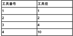
- the machining state adding unit 17 obtains a correspondence table between tool numbers and tool diameters. In the table of Fig. 3, tool number "1" corresponds to tool diameter "1", tool number "2” corresponds to tool diameter "2", tool number "3" corresponds to tool diameter "4", and tool number "4" corresponds to tool diameter "10".
- the correspondence between tool numbers and tool diameters can be obtained from a tool management system or the like.
- the tool management system is an existing technology.
- the tool management system manages information such as machining programs and tool lists.
- the machining state adding unit 17 adds the machining state (including modal data serving as a criterion for determining the machining state) to the point sequence data acquired by the point sequence data acquiring unit 15 .
- the point sequence data is time series data in which time and coordinates are associated.
- the "machining state" of the point sequence data is added to the "time” and "value” of the point sequence data.
- the point sequence data from time “0" to less than “50” corresponds to the machining state "fast forward”
- the point sequence data from time “50” to less than “60” corresponds to the machining state "rough cutting”
- the point sequence data from time “60” to less than "1000” corresponds to the machining state "fast forward”
- the point sequence data from time "1000” onwards corresponds to the machining state "finishing”.
- the tool diameter can be used as data to represent the machining state.
- the "tool diameter” is added to the "time” of the point sequence data and the "value" of the point sequence data.
- the tool diameter for rapid traverse is set to "-1.”
- a tool diameter of "-1" means that no cutting is performed.
- the data selection unit 16 selects point sequence data to be used in the simulation image.
- a tolerance value is used to select the data.
- the tolerance value will be explained with reference to FIG. 6.
- the tolerance value means the allowable deviation of three consecutive point sequence data. The deviation is calculated by selecting point P2 and three points (P1, P2, P3) before and after it, and connecting the previous and next points with lines from start point P1 to end point P3. Then, the distance between point P2 and the line segment connecting P1 and P3 is calculated. If this distance (called the deviation) is greater than the tolerance value, it is determined that the deviation of point P2 exceeds the allowable value.
- step 1 the starting point P1 of the point sequence data is determined.
- the black circle point is the starting point P1.
- three points (P1, P2, P3) starting from the black circle point P1 are selected, and the deviation of P2 is calculated.
- P2 is removed from the point sequence data.
- step 3 three points (P1, P3, P4) excluding P2 are selected.
- the data selection unit calculates the deviation of P3 based on the new three points (P1, P3, P4).
- the deviation of P3 among the new three points (P1, P3, P4) is equal to or greater than the tolerance value.
- the data selection unit 16 sets P3 as the new starting point.
- step S5 the data selection unit 16 selects three points (P3, P4, P5) starting from P3, and finds the deviation of P4. The deviation of P4 is equal to or greater than the tolerance value.
- step S6 the data selection unit 16 sets P4 as the new starting point.
- step 7 the data selection unit 16 selects three points (P4, P5, P6) starting from P4, and finds the deviation of P5. Since the deviation of P5 is smaller than the tolerance value, P5 is excluded from the point sequence data, and three new points (P4, P6, P7) starting from P4 are selected. The data selection unit 16 repeats this process to select point sequence data.
- FIG. 8 is a table showing the correspondence between the machining state and the tolerance value.
- the machining state “fast forward” is associated with the selection method "not selected”
- the machining state “finishing” with the tolerance value “T3 ( ⁇ m)” The relationship between the machining state and the tolerance value is T1>T2>T3.
- the tolerance value "T1" for "rough cutting” is smaller than the tolerance value "T2” for “semi-finishing", which is smaller than the tolerance value "T3” for “finishing”.
- the more importance is placed on precision in the machining, the smaller the tolerance value.
- the data selection unit 16 calculates the deviation of the three points, and if the deviation is smaller than the tolerance value "T1 ( ⁇ m)", it excludes the middle point from the point sequence data. On the other hand, if the deviation is equal to or larger than the tolerance value "T1 ( ⁇ m)", it selects the middle point as the point sequence data and sets it as a new starting point.
- the data selection unit 16 calculates the deviation of the three points, and if the deviation is smaller than the tolerance value "T2 ( ⁇ m)", it excludes the middle point from the point sequence data.
- the data selection unit 16 calculates the deviation of the three points, and if the deviation is smaller than the tolerance value "T3 ( ⁇ m)", it excludes the middle point from the point sequence data. On the other hand, if the deviation is equal to or larger than the tolerance value "T3 ( ⁇ m)", it selects the middle point as the point sequence data and sets it as a new starting point.
- the relationship between the machining state and the tolerance value is T1>T2>T3, so for the same point sequence data, the more emphasis is placed on precision in machining such as "finishing," the more point sequence data is used to create the selected simulation image, and the less emphasis is placed on precision in machining such as "rough cutting,” the more point sequence data is used to create the selected simulation image.
- tool diameter and tolerance value Generally, tools with small diameters are used for high-precision machining. Small tolerance values are associated with machining using tools with small diameters.
- the simulation unit 18 stores three-dimensional image data of the tool shape and the workpiece shape.
- the simulation unit 18 moves the three-dimensional image data of the tool along the point sequence data.
- the simulation unit 18 calculates the cutting area of the tool from the three-dimensional image data of the workpiece, removes the cutting area from the workpiece surface, and creates a simulation image that visually represents the cutting process.
- the number of point sequence data processed by the simulation unit 18 varies depending on the tolerance value.
- the tolerance value T3 in "rough cutting” is the highest. In “rough cutting”, it is not necessary to reflect small changes in the point sequence data in the simulation image. In “rough cutting”, small deviations are ignored, so the number of point sequence data to be selected is reduced.
- the tolerance value T2 of "semi-finishing” is smaller than the tolerance value T1 of "rough cutting.”
- Semi-finishing requires higher accuracy than "rough cutting,” but does not require the same high accuracy as “finishing.”
- the tolerance value T3 is the lowest. For “finishing,” which requires high accuracy, even if the change in the point sequence data is small, the point sequence data in which the change occurred is selected and reflected in the simulation image, so that a highly accurate simulation image can be created.
- step S10 is a flow chart for explaining the operation of the numerical control device 100 of this embodiment.
- the operation of the numerical control device 100 differs between (1) a case where actual machining is not performed and (2) a case where actual machining is performed.
- step S10 the program analysis unit 11 analyzes the machining program (step S11), the interpolation unit 12 calculates a command value per command cycle (step S12), and the command unit 13 outputs a control pulse corresponding to the command value calculated by the interpolation unit 12 to the motor control unit 14 (step S13).
- the motor control unit 14 controls the motor of the machine tool according to commands from the command unit 13.
- the motor is provided with a measuring device such as an encoder.
- the point sequence data acquisition unit 15 acquires the amount of motor rotation (corresponding to the amount of movement of the axis) from the motor.
- the point sequence data acquisition unit 15 acquires point sequence data, which is a set of coordinate positions of the tool (the movement path of the tool), based on the amount of motor rotation (step S14).
- step S10 If actual machining is not involved (step S10; No), the program analysis unit 11 generates point sequence data by analyzing the machining program (step S15).
- the point sequence data corresponds to a set of coordinate positions of the tool (the tool's movement path).
- the point sequence data acquisition unit 15 acquires the point sequence data generated by the program analysis unit 11 (step S16).
- the machining state addition unit 17 judges the machining state of the machine tool when the point sequence data was acquired based on the modal data (step S17).
- the machining state includes "rough cutting”, “semi-finishing", “finishing”, etc.
- the machining state is judged using the program number, tool number, tool diameter, machining program comment, etc.
- the machining state adding section 17 adds machining state information (which may be modal data) to the point sequence data acquired by the point sequence data acquiring section 15 (step S18).
- the data selection unit 16 calculates the deviation of the three points from the point sequence data acquired by the point sequence data acquisition unit 15 (step S19).
- the tolerance value which is the allowable deviation value, is determined by the machining state of the machine tool when the point sequence data is acquired.
- the tolerance value in the "rough cutting” machining state is "T1”
- the tolerance value in the "semi-finish” machining state is "T2”
- the tolerance value in the "finish” machining state is "T3”.
- the data selection unit 16 compares the deviation with the tolerance value, and selects points whose deviation is equal to or greater than the tolerance value as point sequence data for creating a simulation image (step S20).
- the change in the point sequence data is small, so the data is excluded from the point sequence data for creating a simulation image. If the deviation of the three points is equal to or greater than the tolerance value, the change in the point sequence data is large, so the middle point of the three points is selected.
- the data selection unit 16 checks whether the final data of the point sequence data has been processed, and if the final data of the point sequence data has not been processed (step S21; No), it proceeds to step S19, selects three points starting from the point selected in step S20, and calculates the deviation. If the final data of the point sequence data has been processed (step S21; Yes), the data selection unit 16 ends the selection of the point sequence data.
- the simulation unit 18 creates a simulation image of the machining using the point sequence data acquired from the data selection unit 16 (step S22).
- the number of point sequence data for creating the simulation image is adjusted according to the machining state and the deviation of the point sequence data. This reduces the memory load and calculation load required for the simulation.
- the types of simulation include a simulation of the surface quality of the cut surface of a workpiece, and a machine simulation that visualizes the movement of a machine when a program is executed using a three-dimensional model.
- Figure 10 is a hardware configuration diagram of the numerical control device 100.
- the numerical control device 100 is equipped with a CPU 111 that controls the numerical control device 100 as a whole, a ROM 112 that records programs and data, and a RAM 113 for temporarily expanding data.
- the CPU 111 reads out the system program recorded in the ROM 112 via the bus and executes the workaround according to the system program.
- the non-volatile memory 114 is backed up by, for example, a battery (not shown), and retains its stored state even when the power supply to the numerical control device 100 is turned off.
- the non-volatile memory 114 stores various data, such as programs read from the external device 120 via the interfaces 115, 118, and 119, and operation inputs input via the input unit 30.
- the non-volatile memory 114 may also store programs and data for executing the numerical control device 100 of this embodiment.
- the display unit 70 displays various data, measurement results, causes of invalid data, and the like.
- the interface 115 is an interface for connecting the numerical control device 100 to an external device 120 such as an adapter. Programs, various parameters, and the like are read from the external device 120.
- the interface 118 is an interface for connecting the numerical control device 100 to a display unit 70 such as a liquid crystal display. The display unit 70 displays various data loaded onto the memory, data obtained as a result of execution of a program, and the like.
- the interface 119 is an interface for connecting the numerical control device 100 to an input unit 30 such as a keyboard, a pointing device, etc. The input unit 30 passes instructions, data, etc. based on operations by an operator to the CPU 111 via the interface 119.
- the simulation device (100) comprises a program analysis unit (11) that analyzes a machining program, a point sequence data acquisition unit (15) that acquires point sequence data in which tool positions are arranged in chronological order based on the analysis results of the machining program, a data selection unit (16) that selects point sequence data to be used for creating a simulation image based on modal data at the time the point sequence data was acquired, and a simulation unit (18) that uses the selected point sequence data to create a simulation image that visually represents the machining process.
- a program analysis unit (11) that analyzes a machining program
- a point sequence data acquisition unit that acquires point sequence data in which tool positions are arranged in chronological order based on the analysis results of the machining program
- a data selection unit (16) that selects point sequence data to be used for creating a simulation image based on modal data at the time the point sequence data was acquired
- a simulation unit (18) that uses the selected point sequence data to create a simulation image that visually represents the machining process.
- the simulation device (100) includes a machining state adding unit (17) that judges the machining state based on the modal data and adds the machining state to the point sequence data, and the data selecting unit (16) selects the point sequence data based on the machining state.
- the machining state is associated with a tolerance value, and the data selection unit (16) calculates a deviation of a point included in the point sequence data from a line segment passing through adjacent points before and after the point, and selects the point sequence data using the tolerance value as a threshold value for the deviation.
- the machining state includes at least one of rough cutting, semi-finishing, and finishing.
- the data selection unit (16) does not select point sequence data in which the machining state is fast forward.
- the tolerance value is smaller as the machining state places greater importance on precision.
- the point sequence data acquisition unit (15) acquires point sequence data in actual machining.
- the point sequence data acquisition unit (15) acquires point sequence data obtained from a control command for controlling a servo motor based on the machining program.
- the modal data is a program number.
- the modal data is a tool number.
- the storage medium (112, 113, 114) stores instructions for causing one or more processors (111) to execute processing to analyze a machining program, acquire point sequence data in which tool positions are arranged in chronological order based on the analysis results of the machining program, select point sequence data to be used for creating a simulation image based on modal data at the time when the point sequence data was acquired, and create a simulation image that visually represents the machining process using the selected point sequence data.
Landscapes
- Engineering & Computer Science (AREA)
- Human Computer Interaction (AREA)
- Manufacturing & Machinery (AREA)
- Physics & Mathematics (AREA)
- General Physics & Mathematics (AREA)
- Automation & Control Theory (AREA)
- Numerical Control (AREA)
Abstract
L'invention concerne un dispositif de simulation qui analyse un programme d'usinage, acquiert des données de séquence de points dans lesquelles des positions d'un outil sont agencées dans une série chronologique sur la base du résultat d'analyse du programme d'usinage, sélectionne des données de séquence de points à utiliser pour créer une image de simulation sur la base de données modales au moment où les données de séquence de points ont été acquises, et utilise les données de séquence de points sélectionnées pour créer une image de simulation représentant visuellement un processus de découpe.
Priority Applications (1)
| Application Number | Priority Date | Filing Date | Title |
|---|---|---|---|
| PCT/JP2023/021229 WO2024252583A1 (fr) | 2023-06-07 | 2023-06-07 | Dispositif de simulation et support de stockage lisible par ordinateur |
Applications Claiming Priority (1)
| Application Number | Priority Date | Filing Date | Title |
|---|---|---|---|
| PCT/JP2023/021229 WO2024252583A1 (fr) | 2023-06-07 | 2023-06-07 | Dispositif de simulation et support de stockage lisible par ordinateur |
Publications (1)
| Publication Number | Publication Date |
|---|---|
| WO2024252583A1 true WO2024252583A1 (fr) | 2024-12-12 |
Family
ID=93795426
Family Applications (1)
| Application Number | Title | Priority Date | Filing Date |
|---|---|---|---|
| PCT/JP2023/021229 Ceased WO2024252583A1 (fr) | 2023-06-07 | 2023-06-07 | Dispositif de simulation et support de stockage lisible par ordinateur |
Country Status (1)
| Country | Link |
|---|---|
| WO (1) | WO2024252583A1 (fr) |
Citations (7)
| Publication number | Priority date | Publication date | Assignee | Title |
|---|---|---|---|---|
| JPH0594207A (ja) * | 1991-10-03 | 1993-04-16 | Nec Software Ltd | 荒取り用カツタパス生成システム |
| JPH05158518A (ja) * | 1991-12-05 | 1993-06-25 | Okuma Mach Works Ltd | 数値制御装置における途中起動方法 |
| JP2012014601A (ja) * | 2010-07-05 | 2012-01-19 | Jtekt Corp | 加工シミュレーション装置および最適工程決定装置 |
| JP2020086759A (ja) * | 2018-11-21 | 2020-06-04 | ファナック株式会社 | 3次元モデル作成装置、加工シミュレーション装置、工具経路自動生成装置 |
| WO2020179798A1 (fr) * | 2019-03-05 | 2020-09-10 | 三菱電機株式会社 | Dispositif de conversion de programme d'usinage, dispositif de commande numérique, procédé de conversion de programme d'usinage et dispositif d'apprentissage automatique |
| JP2021056835A (ja) * | 2019-09-30 | 2021-04-08 | ファナック株式会社 | シミュレーション装置 |
| WO2023073835A1 (fr) * | 2021-10-27 | 2023-05-04 | ファナック株式会社 | Dispositif de sélection, dispositif de simulation et dispositif de commande de communication |
-
2023
- 2023-06-07 WO PCT/JP2023/021229 patent/WO2024252583A1/fr not_active Ceased
Patent Citations (7)
| Publication number | Priority date | Publication date | Assignee | Title |
|---|---|---|---|---|
| JPH0594207A (ja) * | 1991-10-03 | 1993-04-16 | Nec Software Ltd | 荒取り用カツタパス生成システム |
| JPH05158518A (ja) * | 1991-12-05 | 1993-06-25 | Okuma Mach Works Ltd | 数値制御装置における途中起動方法 |
| JP2012014601A (ja) * | 2010-07-05 | 2012-01-19 | Jtekt Corp | 加工シミュレーション装置および最適工程決定装置 |
| JP2020086759A (ja) * | 2018-11-21 | 2020-06-04 | ファナック株式会社 | 3次元モデル作成装置、加工シミュレーション装置、工具経路自動生成装置 |
| WO2020179798A1 (fr) * | 2019-03-05 | 2020-09-10 | 三菱電機株式会社 | Dispositif de conversion de programme d'usinage, dispositif de commande numérique, procédé de conversion de programme d'usinage et dispositif d'apprentissage automatique |
| JP2021056835A (ja) * | 2019-09-30 | 2021-04-08 | ファナック株式会社 | シミュレーション装置 |
| WO2023073835A1 (fr) * | 2021-10-27 | 2023-05-04 | ファナック株式会社 | Dispositif de sélection, dispositif de simulation et dispositif de commande de communication |
Similar Documents
| Publication | Publication Date | Title |
|---|---|---|
| JP4920785B2 (ja) | 数値制御方法及びその装置 | |
| JP6335925B2 (ja) | 工作機械の制御装置 | |
| JP6646027B2 (ja) | ポストプロセッサ装置、加工プログラム生成方法、cnc加工システム及び加工プログラム生成用プログラム | |
| JP6740199B2 (ja) | 数値制御装置、cnc工作機械、数値制御方法及び数値制御用プログラム | |
| US20210247734A1 (en) | Numerical control device and numerical control method | |
| TWI459167B (zh) | 用於控制可動工具的方法,系統以及電腦可讀取媒體 | |
| JP7473321B2 (ja) | シミュレーション装置、数値制御装置、及びシミュレーション方法 | |
| JP2017204072A (ja) | 加工プログラム処理装置およびこれを備えた多軸加工機 | |
| JP7011064B2 (ja) | ツールパス仮想化および最適化システム、方法および装置 | |
| JP2017151633A (ja) | スカイビング加工におけるテーパ加工でのテーパ角補正機能を有する数値制御装置 | |
| CN111045391A (zh) | 加工信息记录装置、加工信息记录方法和计算机可读介质 | |
| WO2021014749A1 (fr) | Système de génération de programme à commande numérique et procédé de génération de programme à commande numérique | |
| JP6638979B2 (ja) | 加工工程管理機能付き数値制御装置および加工工程管理プログラム | |
| US20230286169A1 (en) | Numerical control system and robot control method | |
| US10444721B2 (en) | Simulation apparatus, program generating device, controller, and display method for computer | |
| JP6034835B2 (ja) | サイクルタイムを短縮するための情報を提示する数値制御装置 | |
| JP2000235411A (ja) | 加工情報を用いた数値制御装置 | |
| JP7654172B1 (ja) | 加工プログラム修正支援装置、加工プログラム修正支援方法および加工システム | |
| WO2024252583A1 (fr) | Dispositif de simulation et support de stockage lisible par ordinateur | |
| JP2020181398A (ja) | 波形表示装置、及び波形表示方法 | |
| JP7504687B2 (ja) | 切削加工支援システム | |
| WO2022138843A1 (fr) | Dispositif de commande numérique | |
| JP2024136846A (ja) | 切削加工に用いる振動特性データベース、切削加工の安定性評価装置、切削加工プログラム生成装置、切削加工の安定性評価方法、および切削加工プログラム生成方法 | |
| JP6316919B2 (ja) | 工作機械の数値制御装置 | |
| JP6935606B1 (ja) | 情報処理装置および情報処理プログラム |
Legal Events
| Date | Code | Title | Description |
|---|---|---|---|
| 121 | Ep: the epo has been informed by wipo that ep was designated in this application |
Ref document number: 23940684 Country of ref document: EP Kind code of ref document: A1 |
|
| NENP | Non-entry into the national phase |
Ref country code: DE |