WO2024252584A1 - Dispositif et procédé d'impression - Google Patents
Dispositif et procédé d'impression Download PDFInfo
- Publication number
- WO2024252584A1 WO2024252584A1 PCT/JP2023/021230 JP2023021230W WO2024252584A1 WO 2024252584 A1 WO2024252584 A1 WO 2024252584A1 JP 2023021230 W JP2023021230 W JP 2023021230W WO 2024252584 A1 WO2024252584 A1 WO 2024252584A1
- Authority
- WO
- WIPO (PCT)
- Prior art keywords
- mask
- unit
- stopper
- screen mask
- printing
- Prior art date
- Legal status (The legal status is an assumption and is not a legal conclusion. Google has not performed a legal analysis and makes no representation as to the accuracy of the status listed.)
- Ceased
Links
Images



Classifications
-
- B—PERFORMING OPERATIONS; TRANSPORTING
- B41—PRINTING; LINING MACHINES; TYPEWRITERS; STAMPS
- B41F—PRINTING MACHINES OR PRESSES
- B41F15/00—Screen printers
- B41F15/08—Machines
- B41F15/0881—Machines for printing on polyhedral articles
-
- B—PERFORMING OPERATIONS; TRANSPORTING
- B41—PRINTING; LINING MACHINES; TYPEWRITERS; STAMPS
- B41F—PRINTING MACHINES OR PRESSES
- B41F15/00—Screen printers
- B41F15/14—Details
- B41F15/16—Printing tables
- B41F15/18—Supports for workpieces
- B41F15/26—Supports for workpieces for articles with flat surfaces
-
- B—PERFORMING OPERATIONS; TRANSPORTING
- B41—PRINTING; LINING MACHINES; TYPEWRITERS; STAMPS
- B41F—PRINTING MACHINES OR PRESSES
- B41F15/00—Screen printers
- B41F15/14—Details
- B41F15/34—Screens, Frames; Holders therefor
- B41F15/36—Screens, Frames; Holders therefor flat
-
- B—PERFORMING OPERATIONS; TRANSPORTING
- B41—PRINTING; LINING MACHINES; TYPEWRITERS; STAMPS
- B41F—PRINTING MACHINES OR PRESSES
- B41F33/00—Indicating, counting, warning, control or safety devices
- B41F33/02—Arrangements of indicating devices, e.g. counters
-
- H—ELECTRICITY
- H05—ELECTRIC TECHNIQUES NOT OTHERWISE PROVIDED FOR
- H05K—PRINTED CIRCUITS; CASINGS OR CONSTRUCTIONAL DETAILS OF ELECTRIC APPARATUS; MANUFACTURE OF ASSEMBLAGES OF ELECTRICAL COMPONENTS
- H05K3/00—Apparatus or processes for manufacturing printed circuits
- H05K3/10—Apparatus or processes for manufacturing printed circuits in which conductive material is applied to the insulating support in such a manner as to form the desired conductive pattern
- H05K3/12—Apparatus or processes for manufacturing printed circuits in which conductive material is applied to the insulating support in such a manner as to form the desired conductive pattern using thick film techniques, e.g. printing techniques to apply the conductive material or similar techniques for applying conductive paste or ink patterns
- H05K3/1216—Apparatus or processes for manufacturing printed circuits in which conductive material is applied to the insulating support in such a manner as to form the desired conductive pattern using thick film techniques, e.g. printing techniques to apply the conductive material or similar techniques for applying conductive paste or ink patterns by screen printing or stencil printing
-
- H—ELECTRICITY
- H05—ELECTRIC TECHNIQUES NOT OTHERWISE PROVIDED FOR
- H05K—PRINTED CIRCUITS; CASINGS OR CONSTRUCTIONAL DETAILS OF ELECTRIC APPARATUS; MANUFACTURE OF ASSEMBLAGES OF ELECTRICAL COMPONENTS
- H05K3/00—Apparatus or processes for manufacturing printed circuits
- H05K3/10—Apparatus or processes for manufacturing printed circuits in which conductive material is applied to the insulating support in such a manner as to form the desired conductive pattern
- H05K3/12—Apparatus or processes for manufacturing printed circuits in which conductive material is applied to the insulating support in such a manner as to form the desired conductive pattern using thick film techniques, e.g. printing techniques to apply the conductive material or similar techniques for applying conductive paste or ink patterns
- H05K3/1216—Apparatus or processes for manufacturing printed circuits in which conductive material is applied to the insulating support in such a manner as to form the desired conductive pattern using thick film techniques, e.g. printing techniques to apply the conductive material or similar techniques for applying conductive paste or ink patterns by screen printing or stencil printing
- H05K3/1233—Methods or means for supplying the conductive material and for forcing it through the screen or stencil
-
- H—ELECTRICITY
- H05—ELECTRIC TECHNIQUES NOT OTHERWISE PROVIDED FOR
- H05K—PRINTED CIRCUITS; CASINGS OR CONSTRUCTIONAL DETAILS OF ELECTRIC APPARATUS; MANUFACTURE OF ASSEMBLAGES OF ELECTRICAL COMPONENTS
- H05K3/00—Apparatus or processes for manufacturing printed circuits
- H05K3/30—Assembling printed circuits with electric components, e.g. with resistors
- H05K3/32—Assembling printed circuits with electric components, e.g. with resistors electrically connecting electric components or wires to printed circuits
- H05K3/34—Assembling printed circuits with electric components, e.g. with resistors electrically connecting electric components or wires to printed circuits by soldering
- H05K3/3465—Application of solder
- H05K3/3485—Application of solder paste, slurry or powder
-
- B—PERFORMING OPERATIONS; TRANSPORTING
- B41—PRINTING; LINING MACHINES; TYPEWRITERS; STAMPS
- B41P—INDEXING SCHEME RELATING TO PRINTING, LINING MACHINES, TYPEWRITERS, AND TO STAMPS
- B41P2215/00—Screen printing machines
- B41P2215/50—Screen printing machines for particular purposes
-
- H—ELECTRICITY
- H05—ELECTRIC TECHNIQUES NOT OTHERWISE PROVIDED FOR
- H05K—PRINTED CIRCUITS; CASINGS OR CONSTRUCTIONAL DETAILS OF ELECTRIC APPARATUS; MANUFACTURE OF ASSEMBLAGES OF ELECTRICAL COMPONENTS
- H05K2203/00—Indexing scheme relating to apparatus or processes for manufacturing printed circuits covered by H05K3/00
- H05K2203/01—Tools for processing; Objects used during processing
- H05K2203/0104—Tools for processing; Objects used during processing for patterning or coating
- H05K2203/0139—Blade or squeegee, e.g. for screen printing or filling of holes
Definitions
- This specification discloses a printing device and a printing method.
- a system in which an operator inputs information such as the size and opening position of the screen mask, and a stopper that positions the screen mask in a position according to the input information (see, for example, Patent Document 1).
- the stopper is disposed on the print head and is movable, so it is said to be easily adaptable even if the size of the screen mask is changed.
- This disclosure has been made in consideration of these problems, and its main objective is to provide a printing device and printing method that can execute printing processes more efficiently.
- the printing device and printing method disclosed in this specification employ the following measures to achieve the above-mentioned main objective.
- the mask stopper is positioned based on that position information, eliminating the need for repositioning, and allowing for more efficient printing.
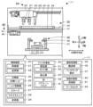
- FIG. 1 is a schematic explanatory diagram showing an example of a mounting system 10.
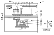
- 3 is an explanatory diagram showing an example of a printing unit 24, a mask working unit 30, and a substrate processing unit 35.
- FIG. 4 is a flowchart showing an example of a print processing routine.
- FIG. 4 is an explanatory diagram showing an example of position confirmation by the mark camera 42 in the printing process.
- 5A to 5C are explanatory diagrams showing an example of a printing operation by a squeegee 27 in a printing process.
- FIG. 13 is an explanatory diagram showing an example of standby at the arrangement position of the mask stopper 28.
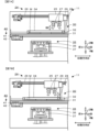
- 11A to 11C are explanatory diagrams showing an example of a position adjustment process when the screen mask M is excessively pressed.
- 11A and 11B are explanatory diagrams showing an example of a position adjustment process when the screen mask M has not yet arrived.
- FIG. 1 is a schematic diagram showing an example of a mounting system 10 and a printing device 11 of the present disclosure.
- FIG. 2 is a diagram showing an example of a printing unit 24, a masking unit 30, and a board processing unit 35.
- the mounting system 10 includes a printing device 11, a print inspection device 12, a storage device 13, a mounting device 15, a mounting inspection device 16, a loader 18, a reflow device (not shown), and a management computer (PC) 19.
- the mounting system 10 is configured as a production line in which, for example, downstream of the printing device 11, mounting devices 15 that mount components P on a board S as a processing target are arranged in the transport direction of the board S.
- the left-right direction (X-axis), front-back direction (Y-axis), and up-down direction (Z-axis) are as shown in FIGS. 1, 4 to 8.
- the print inspection device 12 is a device that inspects the state of a viscous fluid such as solder paste printed on the board S by the printing device 11.
- the storage device 13 is a temporary storage location for feeders that hold components.
- the mounting device 15 is a device that executes a mounting process that places components on the board S.
- the mounting inspection device 16 is a device that inspects the state of the components mounted on the board S.
- the loader 18 is a device that moves left and right along the X-axis rail 17 on the front side of the mounting device 15, and automatically attaches and detaches, collects and replenishes mounting-related members such as feeders used in the mounting device 15.
- the reflow device is a device that reflows a board on which solder has been printed and components P have been mounted.
- the management PC 19 is a device that manages information about each device in the mounting system 10. This management PC 19 manages the progress of each device on the production line that performs the mounting process.
- the printing device 11 is a device that prints solder, which is a viscous fluid placed on the upper surface of a screen mask M, through pattern holes formed in the screen mask M by using a squeegee 27 to push the solder into the pattern holes formed in the screen mask M onto a substrate S, which is an object to be processed below.
- the "object to be processed” include a substrate S on which components are mounted and a three-dimensional base material.
- the "viscous fluid” include solder paste, conductive paste, and adhesive.
- the substrate S and solder paste will be described as examples.
- the screen mask M is fixed inside a frame 34.
- the printing device 11 includes a control device 20, a printing unit 24, a mask working unit 30, a substrate processing unit 35, and a mobile working unit 40.
- the control device 20 is configured as a microprocessor centered on the control unit 21 having a CPU, and controls the entire printing device 11.
- the control device 20 includes the control unit 21 and a memory unit 22.
- the memory unit 22 stores information and is a large-capacity storage medium such as an HDD or flash memory.
- the memory unit 22 stores print jobs including information on the substrate S to be printed and information on the screen mask M, and a print processing program for printing the substrate S.
- the control device 20 outputs signals to the printing unit 24, the mask work unit 30, the substrate processing unit 35, the mobile work unit 40, and the management PC 19 as an external device.
- the control device 20 also inputs signals from the printing unit 24, the mask work unit 30, the substrate processing unit 35, the mobile work unit 40, and the management PC 19 as an external device.
- the control unit 21 which will be described in detail later, executes a positioning process to acquire position information for aligning the screen mask M fixed to the mask work unit 30 and the substrate S fixed to the substrate processing unit 35 at a predetermined printing position.
- the control unit 21 also stores the acquired position information in the storage unit 22, and executes a process of placing the mask stopper 28 at a placement position where the screen mask M stops at the aligned position based on the stored position information.
- the printing unit 24 is disposed on the upper stage of the printing device 11, and is a unit that uses a screen mask M to print a viscous fluid onto a substrate S.
- the printing unit 24 includes a print head 25, a head moving unit 26, a squeegee lifting unit (not shown), and a squeegee 27.
- the print head 25 is a unit that allows the squeegee 27 to move up and down.
- the head moving unit 26 moves the print head 25 in a predetermined printing direction B (in this case, the front-to-back direction) to print the viscous fluid placed on the upper surface of the screen mask M onto the substrate S using the squeegee 27.
- This head moving unit 26 includes a guide formed in the front-to-back direction, a slider that moves along the guide, and a motor that drives the slider.
- the head moving unit 26 has a linear encoder (not shown) and can control the position of the print head 25 with high precision.
- the squeegee 27 is disposed on the underside of the print head 25 and is raised and lowered by the squeegee lifting unit.
- the printing unit 24 has two squeegees 27 that are used in the front and back directions.
- the lifting unit 29 raises and lowers the mask stopper 28 between a positioning position where the tip of the mask stopper 28 abuts against the screen mask M, a retreat position where the screen mask M is passed, and a frame moving position where the mask stopper 28 is hooked onto the outer edge of the frame 34.
- the mask working section 30 is a unit that positions the screen mask M so that it can be inserted and removed, and places and fixes it in a horizontal position.
- the mask working section 30 is disposed between the printing section 24 and the substrate processing section 35 in the vertical direction, and is a unit that fixes and holds the screen mask M.
- the mask working section 30 has a fixing section 31 and a detection section 33.
- the fixing section 31 supports the screen mask M so that it can be moved in the front-rear direction, and fixes the screen mask M at a predetermined printing position.
- the fixing section 31 has an opening in the center, and the substrate S fixed to the substrate processing section 35 is inserted into this opening.
- the fixing section 31 has a guide section 32 that guides the screen mask M along a predetermined insertion/removal direction, here the front-rear direction.
- the guide 32 is a member that contacts both sides of the screen mask M, and one side of the member can be moved and fixed, and when guiding a screen mask M of a different size, the width of this movable member is changed.
- the detection section 33 is a sensor that detects the rough position of the screen mask M.
- the detection unit 33 may be, for example, a non-contact sensor that is arranged along the guide 32 and detects the position of an object by irradiating and detecting light, or a contact sensor that directly detects contact with an object.
- the control unit 21 can detect whether the screen mask M has reached the printing position based on the detection signal from the detection unit 33.
- the mark camera 42 is an imaging unit that reads the reference mark formed on the underside of the screen mask M and the reference mark formed on the substrate S, and obtains the positional relationship between them.
- the mark camera 42 is configured to be able to simultaneously capture images of the upper and lower sides.
- FIG. 3 is a flow chart showing an example of a printing process routine executed by the control unit 21 of the control device 20.
- This routine is executed by the control unit 21 in response to input from the operator W after the printer 11 is started.
- the operator W fixes the screen mask M to be used in this printing process to the frame 34, adjusts the width of the guide portion 32 to the frame 34, and inserts the frame 34 into the mask working portion 30.
- the operator W also places solder paste on the screen mask M.
- the control unit 21 When this printing process routine is started, the control unit 21 first reads out and acquires a print job including information on the substrate S to be manufactured this time from the storage unit 22 (S100). Next, the control unit 21 causes the substrate processing unit 35 to transport the substrate S and fix it at the printing position (S110). After fixing the substrate S, the control unit 21 determines the current processing status (S120). If the current processing status is the start of printing, the control unit 21 executes a process of aligning and contacting the substrate S with the screen mask M by the substrate processing unit 35 (S130), and performs a positioning process of storing the aligned coordinates as position information in the storage unit 22 (S140).
- FIG. 4 is an explanatory diagram showing an example of position confirmation by the mark camera 42 in the printing process.
- the control unit 21 can obtain the positional relationship between the screen mask M and the substrate S by the mark camera 42 capturing images between the mask work unit 30 and the substrate processing unit 35. If there is a positional misalignment between the screen mask M and the substrate S in S150, the control unit 21 executes the processes from S130 onward. That is, the control unit 21 repeatedly executes the alignment process until no positional misalignment is detected by the mark camera 42. Then, when the alignment is completed, the control unit 21 finally stores the coordinates in the memory unit 22. For example, the control unit 21 stores the coordinates of the rear end position, which is the right end side of the frame 34 in FIG. 2, in the memory unit 22.
- FIG. 5 is an explanatory diagram showing an example of a printing operation by the squeegee 27 in the printing process.
- the control unit 21 brings the substrate S into close contact with the screen mask M at the aligned position, scans the squeegee 27 in the printing direction B, and prints the solder R on the screen mask M onto the substrate S.
- the control unit 21 performs a plate release by separating the substrate S from the screen mask M by the substrate processing unit 35, and causes the substrate S to be transported out (S180).
- control unit 21 determines whether or not all of the substrates S currently being printed have completed printing (S190), and if not all of the current substrates S have completed printing, the control unit 21 executes the process from S110 onward. On the other hand, when all of the current substrates S have completed printing, the control unit 21 ends this routine.
- the control unit 21 checks the positional relationship between the substrate S and the screen mask M brought in in S110 using the mark camera 42 in S150, and if there is a positional misalignment, executes the processing from S130 onwards. That is, the control unit 21 executes a positioning process for the screen mask M to eliminate the positional misalignment. On the other hand, if there is no positional misalignment in S160, the control unit 21 executes a printing process in S170, and executes the processing from S180 onwards.
- the control unit 21 makes the mask stopper 28 wait at the arrangement position where the screen mask M is arranged at the same position as in the positioning process based on the coordinates stored in S140 (S200).
- the printing process may be interrupted and the screen mask M may be pulled out by the operator W to supply solder paste onto the screen mask M or to clean the screen mask M.
- This printing resume time may be, for example, when the printing process is resumed after being interrupted by the operator W's work.
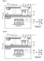
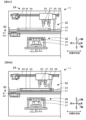
- FIG. 6 is an explanatory diagram showing an example of waiting at the arrangement position of the mask stopper 28, where FIG. 6A shows the screen mask M pulled out and FIG.
- FIG. 6B shows the screen mask M pushed in until it abuts against the mask stopper 28.
- the mask stopper 28 is made to wait at the arrangement position of the screen mask M so that the screen mask M is returned to its original position (FIG. 6A).
- the control unit 21 may place the mask stopper 28 in the placement position when the same screen mask M is inserted or removed.
- the worker W pushes the frame 34 into the mask work unit 30 until it is pressed against the mask stopper 28 after the work is completed (FIG. 6B), and inputs the resumption of the printing process on an operation panel (not shown).
- control unit 21 uses the mark camera 42 to capture the image of the screen mask M and the substrate S, checks their positional relationship (S210, see FIG. 4), and determines whether or not there is misalignment (S220). If there is no misalignment of the screen mask M, the control unit 21 omits the positioning process of the screen mask M and executes the process from S170 onwards, i.e., the printing process. At this time, even if the fixation of the screen mask M is released in the mask working unit 30, the control unit 21 may omit re-executing the positioning process if there is no change in the printing process content.
- the control unit 21 checks the state of misalignment (S230) and executes a position adjustment process in which the mask stopper 28 adjusts the position of the screen mask M to the aligned position (S240 to S250).
- the control unit 21 can determine the state of misalignment based on the detection value of the detection unit 33. For example, if the screen mask M is pushed in and the mask stopper 28 is displaced, a position adjustment process is performed to push the mask stopper back based on the position information stored in the storage unit 22 (S240).
- FIG. 7 is an explanatory diagram showing an example of the position adjustment process when the screen mask M is pushed in excessively, where FIG.
- FIG. 7A shows the excessively pushed state and FIG. 7B shows the mask stopper 28 pushing back the frame 34.
- the control unit 21 performs a process of pushing it back to the placement position by the mask stopper 28 (FIG. 7B).
- This position adjustment process makes the position of the screen mask M appropriate, so that the operator W does not need to perform the work again, and the control unit 21 can execute the printing process as it is without performing the positioning process.
- the mask work unit 30 of this embodiment corresponds to an example of the mask work unit of this disclosure
- the substrate processing unit 35 corresponds to an example of the object processing unit
- the mask stopper 28 corresponds to an example of the mask stopper
- the memory unit 22 corresponds to an example of the memory unit
- the control unit 21 corresponds to an example of the control unit 21.
- the printing device 11 corresponds to the printing device
- the print head 25 corresponds to the print head
- the squeegee 27 corresponds to the squeegee
- the head moving unit 26 corresponds to the stopper moving unit
- the screen mask M corresponds to the screen mask
- the solder R corresponds to the viscous fluid
- the substrate S corresponds to the object to be processed. Note that in this embodiment, an example of the printing method of this disclosure is also clarified by explaining the operation of the printing device 11.
- the printing device 11 of the present embodiment described above is a device that uses a squeegee 27 to print solder R, which is a viscous fluid placed on the top surface of a screen mask M, onto a substrate S, which is an object to be processed.
- the mask stopper 28 is positioned in a location based on that position information, so it is possible to omit repositioning the screen mask M and perform the printing process more efficiently.
- the printing device 11 also includes a head moving unit 26 as a stopper moving unit that moves the mask stopper 28 on the mask work unit 35, and the control unit 21 executes a position adjustment process to control the head moving unit 26 so that the mask stopper 28 adjusts the position of the screen mask M to the aligned position when the screen mask M is misaligned from the aligned position.
- the mask stopper 28 automatically adjusts the screen mask M to the appropriate position, so that the printing process can be performed more efficiently without the need for work by the operator W.
- the control unit 21 controls the head moving unit 26 to push back the mask stopper 28 based on the stored position information.
- the mask stopper 28 automatically adjusts the screen mask M to the appropriate position by pushing back the screen mask M, so that the printing process can be performed more efficiently without the need for work by the operator W.
- the control unit 21 controls the head movement unit 26 to hook the mask stopper 28 onto a part of the screen mask M and pull it in based on the stored position information.
- the screen mask M is pulled in by the mask stopper 28, automatically adjusting the screen mask M to the appropriate position, so that the printing process can be performed more efficiently without the need for work by the operator W.
- the control unit 21 places the mask stopper 28 in the arrangement position when the same screen mask M is inserted or removed.
- the mask stopper in the arrangement places the screen mask in the appropriate position, and thus the printing process can be performed more efficiently.
- the control unit 21 may omit re-execution of the positioning process if there is no change in the printing process content.
- the screen mask is placed in the alignment position by the mask stopper, so that the positioning process can be omitted and the printing process can be performed more efficiently.
- the mask working unit 30 has a guide unit 32 that guides the screen mask along a predetermined insertion/removal direction.
- the movement direction of the mask stopper may be set to be along the insertion/removal direction, so the device configuration can be further simplified.
- the mask stopper 28 is arranged on the print head 25 that is movable in the predetermined printing direction B and has the squeegee 27 arranged thereon. With this printing device 11, the mechanism for moving the mask stopper 28 can be omitted, further simplifying the device configuration.
- the control unit 21 adjusts the position of the screen mask M to the aligned position using the mask stopper 28, but this is not particularly limited, and this position adjustment process may be omitted.
- the control unit 21 pushes the mask stopper 28 back, but this may be omitted.
- the control unit 21 hooks the mask stopper 28 onto a part of the screen mask M and pulls it in, but this may be omitted.
- the mask stopper 28 is also positioned at the arrangement position, so that the printing process can be executed more efficiently.
- control unit 21 positions the mask stopper 28 in the arrangement position when the same screen mask M is inserted or removed, but this is not particularly limited to this. Also, the control unit 21 omits re-execution of the positioning process when the screen mask M is released from its fixed position in the mask working unit 30 and there is no change in the printing process content, but this is not particularly limited to this.
- the mask stopper 28 is disposed on the print head 25 that can move in the printing direction B, and is moved by the head moving unit 26, but this is not particularly limited, and the mask stopper 28 may be disposed on a member other than the print head 25, or may be moved by a stopper moving unit other than the head moving unit 26. Note that, from the viewpoint of simplifying the device configuration, it is more preferable in the printing device 11 that the mask stopper 28 is disposed on the print head 25 that can perform position control with high precision.
- the printing device 11 is described as having a mask stopper 28, but the present invention is not limited to this. It may be configured with only the control device 20 that controls the mask stopper 28, or it may be a control method for the printing device 11, or it may be a printing method. In the control device 20, the control method for the printing device, and the printing method, the printing process can be executed more efficiently by having the mask stopper 28 wait at the placement position.
- the printing method of the present disclosure may be configured as follows:
- the printing method of the present disclosure is a printing method performed by a printing device that includes a mask working unit on which a screen mask is placed and fixed so as to be removable, an object processing unit on which a processing object is transported and fixed, a mask stopper that is movable on the mask working unit and comes into contact with the screen mask to stop the screen mask at a predetermined position, and a storage unit for storing information, and that prints a viscous fluid placed on an upper surface of the screen mask onto the processing object using a squeegee, (a) performing a positioning process to acquire position information obtained by aligning the screen mask fixed to the mask working unit and the processing object fixed to the object processing unit at a predetermined printing position; (b) storing the position information acquired in the step (a) in the storage unit; (c) placing the mask stopper at a placement position where the screen mask stops at the aligned position based on the position information stored in step (b); It includes.
- the mask stopper is positioned based on position information obtained by aligning the screen mask and the object to be processed, so that repositioning processing can be omitted and the printing process can be executed more efficiently.
- this printing method may employ any aspect of the printing device described above, or may include a step that realizes any function of the printing device described above.
- This disclosure can be used in the technical field of devices that process component mounting.
Landscapes
- Engineering & Computer Science (AREA)
- Manufacturing & Machinery (AREA)
- Microelectronics & Electronic Packaging (AREA)
- Mechanical Engineering (AREA)
- Screen Printers (AREA)
- Electric Connection Of Electric Components To Printed Circuits (AREA)
Abstract
La présente invention concerne un dispositif d'impression comprenant : une unité de travail de masque destinée à placer et fixer un masque d'écran de sorte que le masque d'écran peut être amovible ; une unité de traitement d'objet destinée à transporter et fixer un objet à traiter ; une butée de masque qui est mobile sur l'unité de travail de masque, vient en butée sur le masque d'écran, et arrête le masque d'écran à une position prédéterminée ; une unité de stockage qui stocke des informations ; et une unité de commande qui amène le masque d'écran fixé à l'unité de travail de masque et l'objet à traiter fixé à l'unité de traitement d'objet à exécuter un traitement de positionnement pour acquérir des informations de position dans lesquelles le masque d'écran fixé à l'unité de travail de masque et l'objet à traiter fixé à l'unité de traitement d'objet sont alignés à une position d'impression prédéterminée, amène l'unité de stockage à stocker les informations de position acquises, et amène la butée de masque à être disposée, sur la base des informations de position stockées, à la position de disposition à laquelle le masque d'écran est arrêté à la position alignée.
Priority Applications (4)
| Application Number | Priority Date | Filing Date | Title |
|---|---|---|---|
| PCT/JP2023/021230 WO2024252584A1 (fr) | 2023-06-07 | 2023-06-07 | Dispositif et procédé d'impression |
| DE112023006466.0T DE112023006466T5 (de) | 2023-06-07 | 2023-06-07 | Druckvorrichtung und Druckverfahren |
| JP2025525548A JPWO2024252584A1 (fr) | 2023-06-07 | 2023-06-07 | |
| CN202380098758.0A CN121219135A (zh) | 2023-06-07 | 2023-06-07 | 印刷装置及印刷方法 |
Applications Claiming Priority (1)
| Application Number | Priority Date | Filing Date | Title |
|---|---|---|---|
| PCT/JP2023/021230 WO2024252584A1 (fr) | 2023-06-07 | 2023-06-07 | Dispositif et procédé d'impression |
Publications (1)
| Publication Number | Publication Date |
|---|---|
| WO2024252584A1 true WO2024252584A1 (fr) | 2024-12-12 |
Family
ID=93795611
Family Applications (1)
| Application Number | Title | Priority Date | Filing Date |
|---|---|---|---|
| PCT/JP2023/021230 Ceased WO2024252584A1 (fr) | 2023-06-07 | 2023-06-07 | Dispositif et procédé d'impression |
Country Status (4)
| Country | Link |
|---|---|
| JP (1) | JPWO2024252584A1 (fr) |
| CN (1) | CN121219135A (fr) |
| DE (1) | DE112023006466T5 (fr) |
| WO (1) | WO2024252584A1 (fr) |
Citations (7)
| Publication number | Priority date | Publication date | Assignee | Title |
|---|---|---|---|---|
| JP2003211627A (ja) * | 2002-01-21 | 2003-07-29 | Sankyo Seiki Mfg Co Ltd | はんだ印刷機 |
| JP2006289815A (ja) * | 2005-04-12 | 2006-10-26 | Yamaha Motor Co Ltd | 印刷装置およびステンシルの位置決め方法 |
| JP2007237647A (ja) * | 2006-03-10 | 2007-09-20 | Matsushita Electric Ind Co Ltd | スクリーン印刷装置およびスクリーン印刷方法 |
| JP2012236294A (ja) * | 2011-05-10 | 2012-12-06 | Tomoo Matsushita | スクリーンマスクのプリセット装置およびスクリーン印刷方法 |
| US9630393B1 (en) * | 2013-09-25 | 2017-04-25 | Gary Paul Jurman | Screen printing press and method of use |
| JP2018122436A (ja) * | 2017-01-30 | 2018-08-09 | パナソニックIpマネジメント株式会社 | スクリーン印刷装置及びスクリーン印刷方法 |
| JP2020179676A (ja) * | 2020-07-30 | 2020-11-05 | 株式会社Fuji | 印刷システム |
-
2023
- 2023-06-07 DE DE112023006466.0T patent/DE112023006466T5/de active Pending
- 2023-06-07 JP JP2025525548A patent/JPWO2024252584A1/ja active Pending
- 2023-06-07 CN CN202380098758.0A patent/CN121219135A/zh active Pending
- 2023-06-07 WO PCT/JP2023/021230 patent/WO2024252584A1/fr not_active Ceased
Patent Citations (7)
| Publication number | Priority date | Publication date | Assignee | Title |
|---|---|---|---|---|
| JP2003211627A (ja) * | 2002-01-21 | 2003-07-29 | Sankyo Seiki Mfg Co Ltd | はんだ印刷機 |
| JP2006289815A (ja) * | 2005-04-12 | 2006-10-26 | Yamaha Motor Co Ltd | 印刷装置およびステンシルの位置決め方法 |
| JP2007237647A (ja) * | 2006-03-10 | 2007-09-20 | Matsushita Electric Ind Co Ltd | スクリーン印刷装置およびスクリーン印刷方法 |
| JP2012236294A (ja) * | 2011-05-10 | 2012-12-06 | Tomoo Matsushita | スクリーンマスクのプリセット装置およびスクリーン印刷方法 |
| US9630393B1 (en) * | 2013-09-25 | 2017-04-25 | Gary Paul Jurman | Screen printing press and method of use |
| JP2018122436A (ja) * | 2017-01-30 | 2018-08-09 | パナソニックIpマネジメント株式会社 | スクリーン印刷装置及びスクリーン印刷方法 |
| JP2020179676A (ja) * | 2020-07-30 | 2020-11-05 | 株式会社Fuji | 印刷システム |
Also Published As
| Publication number | Publication date |
|---|---|
| CN121219135A (zh) | 2025-12-26 |
| DE112023006466T5 (de) | 2026-03-19 |
| JPWO2024252584A1 (fr) | 2024-12-12 |
Similar Documents
| Publication | Publication Date | Title |
|---|---|---|
| CN109982854B (zh) | 印刷装置 | |
| CN109982852B (zh) | 印刷装置及印刷系统 | |
| JP6293866B2 (ja) | 実装ずれ修正装置および部品実装システム | |
| EP3764763B1 (fr) | Système de montage de composant | |
| JP5957703B2 (ja) | 部品実装システム | |
| JP6850882B2 (ja) | 測定位置決定装置 | |
| CN117083179B (zh) | 更换单元、印刷装置、安装系统以及更换单元的控制方法 | |
| JP6694778B2 (ja) | スクリーン印刷装置 | |
| JP2024014297A (ja) | 部品実装装置 | |
| CN202986305U (zh) | 丝网印刷装置 | |
| WO2022101992A1 (fr) | Dispositif de gestion, procédé de gestion et dispositif de travail | |
| CN121219135A (zh) | 印刷装置及印刷方法 | |
| WO2018055697A1 (fr) | Dispositif de montage de composants | |
| JP7771206B2 (ja) | 基板のクランプ方法、作業装置及び作業システム | |
| CN114128415B (zh) | 安装装置及安装装置的控制方法 | |
| JP7861116B2 (ja) | 対基板作業装置 | |
| JP4340957B2 (ja) | 部品装着方法 | |
| JP7733134B2 (ja) | 枠受けユニット及び印刷装置 | |
| WO2024009506A1 (fr) | Appareil de travail de substrat | |
| JP6043965B2 (ja) | ヘッドメンテナンス装置及び部品実装機 | |
| JP6043966B2 (ja) | ヘッドメンテナンス方法 | |
| JP7642831B2 (ja) | 搬送装置、実装システム及び搬送方法 | |
| JP2024025014A (ja) | 部品搭載装置 | |
| WO2021014505A1 (fr) | Dispositif de montage, système de montage, et procédé de montage et d'inspection | |
| JP2016115754A (ja) | 部品実装装置、表面実装機、及び部品厚み検出方法 |
Legal Events
| Date | Code | Title | Description |
|---|---|---|---|
| 121 | Ep: the epo has been informed by wipo that ep was designated in this application |
Ref document number: 23940685 Country of ref document: EP Kind code of ref document: A1 |
|
| ENP | Entry into the national phase |
Ref document number: 2025525548 Country of ref document: JP Kind code of ref document: A |
|
| WWE | Wipo information: entry into national phase |
Ref document number: 112023006466 Country of ref document: DE |
|
| WWP | Wipo information: published in national office |
Ref document number: 112023006466 Country of ref document: DE |