WO2024252584A1 - 印刷装置及び印刷方法 - Google Patents
印刷装置及び印刷方法 Download PDFInfo
- Publication number
- WO2024252584A1 WO2024252584A1 PCT/JP2023/021230 JP2023021230W WO2024252584A1 WO 2024252584 A1 WO2024252584 A1 WO 2024252584A1 JP 2023021230 W JP2023021230 W JP 2023021230W WO 2024252584 A1 WO2024252584 A1 WO 2024252584A1
- Authority
- WO
- WIPO (PCT)
- Prior art keywords
- mask
- unit
- stopper
- screen mask
- printing
- Prior art date
- Legal status (The legal status is an assumption and is not a legal conclusion. Google has not performed a legal analysis and makes no representation as to the accuracy of the status listed.)
- Ceased
Links
Images


Classifications
-
- B—PERFORMING OPERATIONS; TRANSPORTING
- B41—PRINTING; LINING MACHINES; TYPEWRITERS; STAMPS
- B41F—PRINTING MACHINES OR PRESSES
- B41F15/00—Screen printers
- B41F15/08—Machines
- B41F15/0881—Machines for printing on polyhedral articles
-
- B—PERFORMING OPERATIONS; TRANSPORTING
- B41—PRINTING; LINING MACHINES; TYPEWRITERS; STAMPS
- B41F—PRINTING MACHINES OR PRESSES
- B41F15/00—Screen printers
- B41F15/14—Details
- B41F15/16—Printing tables
- B41F15/18—Supports for workpieces
- B41F15/26—Supports for workpieces for articles with flat surfaces
-
- B—PERFORMING OPERATIONS; TRANSPORTING
- B41—PRINTING; LINING MACHINES; TYPEWRITERS; STAMPS
- B41F—PRINTING MACHINES OR PRESSES
- B41F15/00—Screen printers
- B41F15/14—Details
- B41F15/34—Screens, Frames; Holders therefor
- B41F15/36—Screens, Frames; Holders therefor flat
-
- B—PERFORMING OPERATIONS; TRANSPORTING
- B41—PRINTING; LINING MACHINES; TYPEWRITERS; STAMPS
- B41F—PRINTING MACHINES OR PRESSES
- B41F33/00—Indicating, counting, warning, control or safety devices
- B41F33/02—Arrangements of indicating devices, e.g. counters
-
- H—ELECTRICITY
- H05—ELECTRIC TECHNIQUES NOT OTHERWISE PROVIDED FOR
- H05K—PRINTED CIRCUITS; CASINGS OR CONSTRUCTIONAL DETAILS OF ELECTRIC APPARATUS; MANUFACTURE OF ASSEMBLAGES OF ELECTRICAL COMPONENTS
- H05K3/00—Apparatus or processes for manufacturing printed circuits
- H05K3/10—Apparatus or processes for manufacturing printed circuits in which conductive material is applied to the insulating support in such a manner as to form the desired conductive pattern
- H05K3/12—Apparatus or processes for manufacturing printed circuits in which conductive material is applied to the insulating support in such a manner as to form the desired conductive pattern using thick film techniques, e.g. printing techniques to apply the conductive material or similar techniques for applying conductive paste or ink patterns
- H05K3/1216—Apparatus or processes for manufacturing printed circuits in which conductive material is applied to the insulating support in such a manner as to form the desired conductive pattern using thick film techniques, e.g. printing techniques to apply the conductive material or similar techniques for applying conductive paste or ink patterns by screen printing or stencil printing
- H05K3/1233—Methods or means for supplying the conductive material and for forcing it through the screen or stencil
-
- H—ELECTRICITY
- H05—ELECTRIC TECHNIQUES NOT OTHERWISE PROVIDED FOR
- H05K—PRINTED CIRCUITS; CASINGS OR CONSTRUCTIONAL DETAILS OF ELECTRIC APPARATUS; MANUFACTURE OF ASSEMBLAGES OF ELECTRICAL COMPONENTS
- H05K3/00—Apparatus or processes for manufacturing printed circuits
- H05K3/30—Assembling printed circuits with electric components, e.g. with resistors
- H05K3/32—Assembling printed circuits with electric components, e.g. with resistors electrically connecting electric components or wires to printed circuits
- H05K3/34—Assembling printed circuits with electric components, e.g. with resistors electrically connecting electric components or wires to printed circuits by soldering
- H05K3/3465—Application of solder
- H05K3/3485—Application of solder paste, slurry or powder
-
- B—PERFORMING OPERATIONS; TRANSPORTING
- B41—PRINTING; LINING MACHINES; TYPEWRITERS; STAMPS
- B41P—INDEXING SCHEME RELATING TO PRINTING, LINING MACHINES, TYPEWRITERS, AND TO STAMPS
- B41P2215/00—Screen printing machines
- B41P2215/50—Screen printing machines for particular purposes
-
- H—ELECTRICITY
- H05—ELECTRIC TECHNIQUES NOT OTHERWISE PROVIDED FOR
- H05K—PRINTED CIRCUITS; CASINGS OR CONSTRUCTIONAL DETAILS OF ELECTRIC APPARATUS; MANUFACTURE OF ASSEMBLAGES OF ELECTRICAL COMPONENTS
- H05K2203/00—Indexing scheme relating to apparatus or processes for manufacturing printed circuits covered by H05K3/00
- H05K2203/01—Tools for processing; Objects used during processing
- H05K2203/0104—Tools for processing; Objects used during processing for patterning or coating
- H05K2203/0139—Blade or squeegee, e.g. for screen printing or filling of holes
Definitions
- This specification discloses a printing device and a printing method.
- a system in which an operator inputs information such as the size and opening position of the screen mask, and a stopper that positions the screen mask in a position according to the input information (see, for example, Patent Document 1).
- the stopper is disposed on the print head and is movable, so it is said to be easily adaptable even if the size of the screen mask is changed.
- This disclosure has been made in consideration of these problems, and its main objective is to provide a printing device and printing method that can execute printing processes more efficiently.
- the printing device and printing method disclosed in this specification employ the following measures to achieve the above-mentioned main objective.
- the mask stopper is positioned based on that position information, eliminating the need for repositioning, and allowing for more efficient printing.
- FIG. 1 is a schematic explanatory diagram showing an example of a mounting system 10.
- 3 is an explanatory diagram showing an example of a printing unit 24, a mask working unit 30, and a substrate processing unit 35.
- FIG. 4 is a flowchart showing an example of a print processing routine.
- FIG. 4 is an explanatory diagram showing an example of position confirmation by the mark camera 42 in the printing process.
- 5A to 5C are explanatory diagrams showing an example of a printing operation by a squeegee 27 in a printing process.
- FIG. 13 is an explanatory diagram showing an example of standby at the arrangement position of the mask stopper 28.
- 11A to 11C are explanatory diagrams showing an example of a position adjustment process when the screen mask M is excessively pressed.
- 11A and 11B are explanatory diagrams showing an example of a position adjustment process when the screen mask M has not yet arrived.
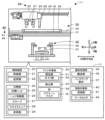
- FIG. 1 is a schematic diagram showing an example of a mounting system 10 and a printing device 11 of the present disclosure.
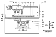
- FIG. 2 is a diagram showing an example of a printing unit 24, a masking unit 30, and a board processing unit 35.
- the mounting system 10 includes a printing device 11, a print inspection device 12, a storage device 13, a mounting device 15, a mounting inspection device 16, a loader 18, a reflow device (not shown), and a management computer (PC) 19.
- the mounting system 10 is configured as a production line in which, for example, downstream of the printing device 11, mounting devices 15 that mount components P on a board S as a processing target are arranged in the transport direction of the board S.
- the left-right direction (X-axis), front-back direction (Y-axis), and up-down direction (Z-axis) are as shown in FIGS. 1, 4 to 8.
- the print inspection device 12 is a device that inspects the state of a viscous fluid such as solder paste printed on the board S by the printing device 11.
- the storage device 13 is a temporary storage location for feeders that hold components.
- the mounting device 15 is a device that executes a mounting process that places components on the board S.
- the mounting inspection device 16 is a device that inspects the state of the components mounted on the board S.
- the loader 18 is a device that moves left and right along the X-axis rail 17 on the front side of the mounting device 15, and automatically attaches and detaches, collects and replenishes mounting-related members such as feeders used in the mounting device 15.
- the reflow device is a device that reflows a board on which solder has been printed and components P have been mounted.
- the management PC 19 is a device that manages information about each device in the mounting system 10. This management PC 19 manages the progress of each device on the production line that performs the mounting process.
- the printing device 11 is a device that prints solder, which is a viscous fluid placed on the upper surface of a screen mask M, through pattern holes formed in the screen mask M by using a squeegee 27 to push the solder into the pattern holes formed in the screen mask M onto a substrate S, which is an object to be processed below.
- the "object to be processed” include a substrate S on which components are mounted and a three-dimensional base material.
- the "viscous fluid” include solder paste, conductive paste, and adhesive.
- the substrate S and solder paste will be described as examples.
- the screen mask M is fixed inside a frame 34.
- the printing device 11 includes a control device 20, a printing unit 24, a mask working unit 30, a substrate processing unit 35, and a mobile working unit 40.
- the control device 20 is configured as a microprocessor centered on the control unit 21 having a CPU, and controls the entire printing device 11.
- the control device 20 includes the control unit 21 and a memory unit 22.
- the memory unit 22 stores information and is a large-capacity storage medium such as an HDD or flash memory.
- the memory unit 22 stores print jobs including information on the substrate S to be printed and information on the screen mask M, and a print processing program for printing the substrate S.
- the control device 20 outputs signals to the printing unit 24, the mask work unit 30, the substrate processing unit 35, the mobile work unit 40, and the management PC 19 as an external device.
- the control device 20 also inputs signals from the printing unit 24, the mask work unit 30, the substrate processing unit 35, the mobile work unit 40, and the management PC 19 as an external device.
- the control unit 21 which will be described in detail later, executes a positioning process to acquire position information for aligning the screen mask M fixed to the mask work unit 30 and the substrate S fixed to the substrate processing unit 35 at a predetermined printing position.
- the control unit 21 also stores the acquired position information in the storage unit 22, and executes a process of placing the mask stopper 28 at a placement position where the screen mask M stops at the aligned position based on the stored position information.
- the printing unit 24 is disposed on the upper stage of the printing device 11, and is a unit that uses a screen mask M to print a viscous fluid onto a substrate S.
- the printing unit 24 includes a print head 25, a head moving unit 26, a squeegee lifting unit (not shown), and a squeegee 27.
- the print head 25 is a unit that allows the squeegee 27 to move up and down.
- the head moving unit 26 moves the print head 25 in a predetermined printing direction B (in this case, the front-to-back direction) to print the viscous fluid placed on the upper surface of the screen mask M onto the substrate S using the squeegee 27.
- This head moving unit 26 includes a guide formed in the front-to-back direction, a slider that moves along the guide, and a motor that drives the slider.
- the head moving unit 26 has a linear encoder (not shown) and can control the position of the print head 25 with high precision.
- the squeegee 27 is disposed on the underside of the print head 25 and is raised and lowered by the squeegee lifting unit.
- the printing unit 24 has two squeegees 27 that are used in the front and back directions.
- the lifting unit 29 raises and lowers the mask stopper 28 between a positioning position where the tip of the mask stopper 28 abuts against the screen mask M, a retreat position where the screen mask M is passed, and a frame moving position where the mask stopper 28 is hooked onto the outer edge of the frame 34.
- the mask working section 30 is a unit that positions the screen mask M so that it can be inserted and removed, and places and fixes it in a horizontal position.
- the mask working section 30 is disposed between the printing section 24 and the substrate processing section 35 in the vertical direction, and is a unit that fixes and holds the screen mask M.
- the mask working section 30 has a fixing section 31 and a detection section 33.
- the fixing section 31 supports the screen mask M so that it can be moved in the front-rear direction, and fixes the screen mask M at a predetermined printing position.
- the fixing section 31 has an opening in the center, and the substrate S fixed to the substrate processing section 35 is inserted into this opening.
- the fixing section 31 has a guide section 32 that guides the screen mask M along a predetermined insertion/removal direction, here the front-rear direction.
- the guide 32 is a member that contacts both sides of the screen mask M, and one side of the member can be moved and fixed, and when guiding a screen mask M of a different size, the width of this movable member is changed.
- the detection section 33 is a sensor that detects the rough position of the screen mask M.
- the detection unit 33 may be, for example, a non-contact sensor that is arranged along the guide 32 and detects the position of an object by irradiating and detecting light, or a contact sensor that directly detects contact with an object.
- the control unit 21 can detect whether the screen mask M has reached the printing position based on the detection signal from the detection unit 33.
- the mark camera 42 is an imaging unit that reads the reference mark formed on the underside of the screen mask M and the reference mark formed on the substrate S, and obtains the positional relationship between them.
- the mark camera 42 is configured to be able to simultaneously capture images of the upper and lower sides.
- FIG. 3 is a flow chart showing an example of a printing process routine executed by the control unit 21 of the control device 20.
- This routine is executed by the control unit 21 in response to input from the operator W after the printer 11 is started.
- the operator W fixes the screen mask M to be used in this printing process to the frame 34, adjusts the width of the guide portion 32 to the frame 34, and inserts the frame 34 into the mask working portion 30.
- the operator W also places solder paste on the screen mask M.
- the control unit 21 When this printing process routine is started, the control unit 21 first reads out and acquires a print job including information on the substrate S to be manufactured this time from the storage unit 22 (S100). Next, the control unit 21 causes the substrate processing unit 35 to transport the substrate S and fix it at the printing position (S110). After fixing the substrate S, the control unit 21 determines the current processing status (S120). If the current processing status is the start of printing, the control unit 21 executes a process of aligning and contacting the substrate S with the screen mask M by the substrate processing unit 35 (S130), and performs a positioning process of storing the aligned coordinates as position information in the storage unit 22 (S140).
- FIG. 4 is an explanatory diagram showing an example of position confirmation by the mark camera 42 in the printing process.
- the control unit 21 can obtain the positional relationship between the screen mask M and the substrate S by the mark camera 42 capturing images between the mask work unit 30 and the substrate processing unit 35. If there is a positional misalignment between the screen mask M and the substrate S in S150, the control unit 21 executes the processes from S130 onward. That is, the control unit 21 repeatedly executes the alignment process until no positional misalignment is detected by the mark camera 42. Then, when the alignment is completed, the control unit 21 finally stores the coordinates in the memory unit 22. For example, the control unit 21 stores the coordinates of the rear end position, which is the right end side of the frame 34 in FIG. 2, in the memory unit 22.
- FIG. 5 is an explanatory diagram showing an example of a printing operation by the squeegee 27 in the printing process.
- the control unit 21 brings the substrate S into close contact with the screen mask M at the aligned position, scans the squeegee 27 in the printing direction B, and prints the solder R on the screen mask M onto the substrate S.
- the control unit 21 performs a plate release by separating the substrate S from the screen mask M by the substrate processing unit 35, and causes the substrate S to be transported out (S180).
- control unit 21 determines whether or not all of the substrates S currently being printed have completed printing (S190), and if not all of the current substrates S have completed printing, the control unit 21 executes the process from S110 onward. On the other hand, when all of the current substrates S have completed printing, the control unit 21 ends this routine.
- the control unit 21 checks the positional relationship between the substrate S and the screen mask M brought in in S110 using the mark camera 42 in S150, and if there is a positional misalignment, executes the processing from S130 onwards. That is, the control unit 21 executes a positioning process for the screen mask M to eliminate the positional misalignment. On the other hand, if there is no positional misalignment in S160, the control unit 21 executes a printing process in S170, and executes the processing from S180 onwards.
- the control unit 21 makes the mask stopper 28 wait at the arrangement position where the screen mask M is arranged at the same position as in the positioning process based on the coordinates stored in S140 (S200).
- the printing process may be interrupted and the screen mask M may be pulled out by the operator W to supply solder paste onto the screen mask M or to clean the screen mask M.
- This printing resume time may be, for example, when the printing process is resumed after being interrupted by the operator W's work.
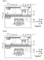
- FIG. 6 is an explanatory diagram showing an example of waiting at the arrangement position of the mask stopper 28, where FIG. 6A shows the screen mask M pulled out and FIG.
- FIG. 6B shows the screen mask M pushed in until it abuts against the mask stopper 28.
- the mask stopper 28 is made to wait at the arrangement position of the screen mask M so that the screen mask M is returned to its original position (FIG. 6A).
- the control unit 21 may place the mask stopper 28 in the placement position when the same screen mask M is inserted or removed.
- the worker W pushes the frame 34 into the mask work unit 30 until it is pressed against the mask stopper 28 after the work is completed (FIG. 6B), and inputs the resumption of the printing process on an operation panel (not shown).
- control unit 21 uses the mark camera 42 to capture the image of the screen mask M and the substrate S, checks their positional relationship (S210, see FIG. 4), and determines whether or not there is misalignment (S220). If there is no misalignment of the screen mask M, the control unit 21 omits the positioning process of the screen mask M and executes the process from S170 onwards, i.e., the printing process. At this time, even if the fixation of the screen mask M is released in the mask working unit 30, the control unit 21 may omit re-executing the positioning process if there is no change in the printing process content.
- the control unit 21 checks the state of misalignment (S230) and executes a position adjustment process in which the mask stopper 28 adjusts the position of the screen mask M to the aligned position (S240 to S250).
- the control unit 21 can determine the state of misalignment based on the detection value of the detection unit 33. For example, if the screen mask M is pushed in and the mask stopper 28 is displaced, a position adjustment process is performed to push the mask stopper back based on the position information stored in the storage unit 22 (S240).
- FIG. 7 is an explanatory diagram showing an example of the position adjustment process when the screen mask M is pushed in excessively, where FIG.
- FIG. 7A shows the excessively pushed state and FIG. 7B shows the mask stopper 28 pushing back the frame 34.
- the control unit 21 performs a process of pushing it back to the placement position by the mask stopper 28 (FIG. 7B).
- This position adjustment process makes the position of the screen mask M appropriate, so that the operator W does not need to perform the work again, and the control unit 21 can execute the printing process as it is without performing the positioning process.
- the mask work unit 30 of this embodiment corresponds to an example of the mask work unit of this disclosure
- the substrate processing unit 35 corresponds to an example of the object processing unit
- the mask stopper 28 corresponds to an example of the mask stopper
- the memory unit 22 corresponds to an example of the memory unit
- the control unit 21 corresponds to an example of the control unit 21.
- the printing device 11 corresponds to the printing device
- the print head 25 corresponds to the print head
- the squeegee 27 corresponds to the squeegee
- the head moving unit 26 corresponds to the stopper moving unit
- the screen mask M corresponds to the screen mask
- the solder R corresponds to the viscous fluid
- the substrate S corresponds to the object to be processed. Note that in this embodiment, an example of the printing method of this disclosure is also clarified by explaining the operation of the printing device 11.
- the printing device 11 of the present embodiment described above is a device that uses a squeegee 27 to print solder R, which is a viscous fluid placed on the top surface of a screen mask M, onto a substrate S, which is an object to be processed.
- the mask stopper 28 is positioned in a location based on that position information, so it is possible to omit repositioning the screen mask M and perform the printing process more efficiently.
- the printing device 11 also includes a head moving unit 26 as a stopper moving unit that moves the mask stopper 28 on the mask work unit 35, and the control unit 21 executes a position adjustment process to control the head moving unit 26 so that the mask stopper 28 adjusts the position of the screen mask M to the aligned position when the screen mask M is misaligned from the aligned position.
- the mask stopper 28 automatically adjusts the screen mask M to the appropriate position, so that the printing process can be performed more efficiently without the need for work by the operator W.
- the control unit 21 controls the head moving unit 26 to push back the mask stopper 28 based on the stored position information.
- the mask stopper 28 automatically adjusts the screen mask M to the appropriate position by pushing back the screen mask M, so that the printing process can be performed more efficiently without the need for work by the operator W.
- the control unit 21 controls the head movement unit 26 to hook the mask stopper 28 onto a part of the screen mask M and pull it in based on the stored position information.
- the screen mask M is pulled in by the mask stopper 28, automatically adjusting the screen mask M to the appropriate position, so that the printing process can be performed more efficiently without the need for work by the operator W.
- the control unit 21 places the mask stopper 28 in the arrangement position when the same screen mask M is inserted or removed.
- the mask stopper in the arrangement places the screen mask in the appropriate position, and thus the printing process can be performed more efficiently.
- the control unit 21 may omit re-execution of the positioning process if there is no change in the printing process content.
- the screen mask is placed in the alignment position by the mask stopper, so that the positioning process can be omitted and the printing process can be performed more efficiently.
- the mask working unit 30 has a guide unit 32 that guides the screen mask along a predetermined insertion/removal direction.
- the movement direction of the mask stopper may be set to be along the insertion/removal direction, so the device configuration can be further simplified.
- the mask stopper 28 is arranged on the print head 25 that is movable in the predetermined printing direction B and has the squeegee 27 arranged thereon. With this printing device 11, the mechanism for moving the mask stopper 28 can be omitted, further simplifying the device configuration.
- the control unit 21 adjusts the position of the screen mask M to the aligned position using the mask stopper 28, but this is not particularly limited, and this position adjustment process may be omitted.
- the control unit 21 pushes the mask stopper 28 back, but this may be omitted.
- the control unit 21 hooks the mask stopper 28 onto a part of the screen mask M and pulls it in, but this may be omitted.
- the mask stopper 28 is also positioned at the arrangement position, so that the printing process can be executed more efficiently.
- control unit 21 positions the mask stopper 28 in the arrangement position when the same screen mask M is inserted or removed, but this is not particularly limited to this. Also, the control unit 21 omits re-execution of the positioning process when the screen mask M is released from its fixed position in the mask working unit 30 and there is no change in the printing process content, but this is not particularly limited to this.
- the mask stopper 28 is disposed on the print head 25 that can move in the printing direction B, and is moved by the head moving unit 26, but this is not particularly limited, and the mask stopper 28 may be disposed on a member other than the print head 25, or may be moved by a stopper moving unit other than the head moving unit 26. Note that, from the viewpoint of simplifying the device configuration, it is more preferable in the printing device 11 that the mask stopper 28 is disposed on the print head 25 that can perform position control with high precision.
- the printing device 11 is described as having a mask stopper 28, but the present invention is not limited to this. It may be configured with only the control device 20 that controls the mask stopper 28, or it may be a control method for the printing device 11, or it may be a printing method. In the control device 20, the control method for the printing device, and the printing method, the printing process can be executed more efficiently by having the mask stopper 28 wait at the placement position.
- the printing method of the present disclosure may be configured as follows:
- the printing method of the present disclosure is a printing method performed by a printing device that includes a mask working unit on which a screen mask is placed and fixed so as to be removable, an object processing unit on which a processing object is transported and fixed, a mask stopper that is movable on the mask working unit and comes into contact with the screen mask to stop the screen mask at a predetermined position, and a storage unit for storing information, and that prints a viscous fluid placed on an upper surface of the screen mask onto the processing object using a squeegee, (a) performing a positioning process to acquire position information obtained by aligning the screen mask fixed to the mask working unit and the processing object fixed to the object processing unit at a predetermined printing position; (b) storing the position information acquired in the step (a) in the storage unit; (c) placing the mask stopper at a placement position where the screen mask stops at the aligned position based on the position information stored in step (b); It includes.
- the mask stopper is positioned based on position information obtained by aligning the screen mask and the object to be processed, so that repositioning processing can be omitted and the printing process can be executed more efficiently.
- this printing method may employ any aspect of the printing device described above, or may include a step that realizes any function of the printing device described above.
- This disclosure can be used in the technical field of devices that process component mounting.
Landscapes
- Engineering & Computer Science (AREA)
- Manufacturing & Machinery (AREA)
- Microelectronics & Electronic Packaging (AREA)
- Mechanical Engineering (AREA)
- Screen Printers (AREA)
- Electric Connection Of Electric Components To Printed Circuits (AREA)
Abstract
本開示の印刷装置は、スクリーンマスクを出し入れ可能に載置、固定するマスク作業部と、処理対象物を搬送、固定する対象物処理部と、マスク作業部上で移動可能でありスクリーンマスクに当接し所定位置でスクリーンマスクを停止させるマスクストッパと、情報を記憶する記憶部と、マスク作業部に固定されたスクリーンマスクと対象物処理部に固定された処理対象物とを所定の印刷位置で位置合わせした位置情報を取得する位置決め処理を実行させ、取得したこの位置情報を記憶部に記憶させ、位置合わせした位置にスクリーンマスクが停止する配置位置へ記憶させた位置情報に基づいてマスクストッパを配置させる制御部と、を備える。
Description
本明細書では、印刷装置及び印刷方法を開示する。
従来、例えば、基板などの処理対象物に対してスクリーンマスクを用いて粘性流体の印刷処理を行う印刷装置において、スクリーンマスクのサイズや開口位置をなどの情報を作業者が入力し、その入力した情報に応じた位置に、スクリーンマスクを位置決めするストッパを配置させるものが提案されている(例えば、特許文献1など参照)。この印刷装置では、ストッパが印刷ヘッドに配設されて移動可能であるため、スクリーンマスクのサイズなどが変更されても、容易に対応できるとしている。
しかしながら、上述した特許文献1の印刷装置では、スクリーンマスクの種別値を入力するものであるので、個々のスクリーンマスクの状態に合うものではなく、ストッパでスクリーンマスクを止めたのちに高精度な印刷処理を実行するには、より高精度である、スクリーンマスクと基板との位置決め処理を行う必要があった。また、特許文献1の印刷装置では、位置決め処理を行ったのちに、例えば清掃やはんだの追加、基板の差し込みなどでスクリーンマスクが移動された場合、更に位置決め処理を行わなければならなかった。位置決め処理の実行には、時間を消費するため、特許文献1の印刷装置では、効率よい印刷処理を実行することができないことがあった。
本開示は、このような課題に鑑みなされたものであり、より効率よく印刷処理を実行することができる印刷装置及び印刷方法を提供することを主目的とする。
本明細書で開示する印刷装置及び印刷方法は、上述の主目的を達成するために以下の手段を採った。
本明細書で開示する印刷装置は、
スクリーンマスクの上面に載せられた粘性流体を、スキージを使って処理対象物上に印刷する印刷装置であって、
前記スクリーンマスクを出し入れ可能に載置、固定するマスク作業部と、
前記処理対象物を搬送、固定する対象物処理部と、
前記マスク作業部上で移動可能であり前記スクリーンマスクに当接し所定位置で前記スクリーンマスクを停止させるマスクストッパと、
情報を記憶する記憶部と、
前記マスク作業部に固定された前記スクリーンマスクと、前記対象物処理部に固定された前記処理対象物と、を所定の印刷位置で位置合わせした位置情報を取得する位置決め処理を実行させ、取得した該位置情報を前記記憶部に記憶させ、前記位置合わせした位置に前記スクリーンマスクが停止する配置位置へ、記憶させた前記位置情報に基づいて前記マスクストッパを配置させる制御部と、
を備えたものである。
この印刷装置では、スクリーンマスクと処理対象物とを位置合わせした位置情報を一度取得すると、その位置情報に基づく配置位置にマスクストッパを配置させるから、再度の位置決め処理を省略することができ、より効率よく印刷処理を実行することができる。
本実施形態を、図面を参照しながら以下に説明する。図1は、本開示の実装システム10及び印刷装置11の一例を示す概略説明図である。図2は、印刷部24、マスク作業部30及び基板処理部35の一例を示す説明図である。実装システム10は、印刷装置11と、印刷検査装置12と、保管装置13と、実装装置15と、実装検査装置16と、ローダ18と、図示しないリフロー装置と、管理コンピュータ(PC)19と、を備えている。実装システム10は、例えば、印刷装置11の下流側に処理対象物としての基板Sに部品Pを実装処理する実装装置15が基板Sの搬送方向に配列された生産ラインとして構成されている。なお、本実施形態において、左右方向(X軸)、前後方向(Y軸)及び上下方向(Z軸)は、図1、4~8に示した通りとする。
印刷検査装置12は、印刷装置11により基板Sに印刷されたはんだペーストなどの粘性流体の状態を検査する装置である。保管装置13は、部品を保持したフィーダの一時保管場所である。実装装置15は、基板Sに部品を配置する実装処理を実行する装置である。実装検査装置16は、基板Sに実装された部品の状態などを検査する装置である。ローダ18は、実装装置15の前面側でX軸レール17に沿って左右方向に移動し、フィーダなど実装装置15に用いられる実装関連部材を自動着脱し、回収及び補給する装置である。リフロー装置は、はんだが印刷され部品Pが実装された基板をリフローする装置である。管理PC19は、実装システム10の各装置の情報を管理する装置である。この管理PC19は、実装処理を行う生産ラインの各装置の進捗状況などを管理する。
印刷装置11は、図2に示すように、スクリーンマスクMの上面に載せられた粘性流体としてのはんだを、スキージ27を使ってスクリーンマスクMに形成されたパターン孔に押し込むことによりそのパターン孔を介して下方の処理対象物としての基板S上に印刷する装置である。ここで「処理対象物」としては、例えば、部品を実装する基板Sや立体物である基材などが挙げられる。「粘性流体」としては、はんだペーストや導電性ペースト、接着剤などが挙げられる。ここでは、基板Sとはんだペーストとを一例として以下説明する。スクリーンマスクMは、枠34の内側に固定されている。印刷装置11は、図2に示すように、制御装置20と、印刷部24と、マスク作業部30と、基板処理部35と、移動作業部40とを備えている。
制御装置20は、CPUを有する制御部21を中心とするマイクロプロセッサとして構成されており、印刷装置11の全体を制御する。制御装置20は、制御部21と、記憶部22とを備えている。記憶部22は、情報を記憶するものであり、HDDやフラッシュメモリなどの大容量記憶媒体である。記憶部22には、印刷処理する基板Sの情報やスクリーンマスクMの情報を含む印刷ジョブや、基板Sへ印刷処理を行う印刷処理プログラムなどが記憶されている。制御装置20は、印刷部24、マスク作業部30、基板処理部35、移動作業部40のほか、外部装置としての管理PC19へ信号を出力する。また、制御装置20は、印刷部24、マスク作業部30、基板処理部35、移動作業部40のほか、外部装置としての管理PC19から信号を入力する。制御部21は、詳しくは後述するが、マスク作業部30に固定されたスクリーンマスクMと、基板処理部35に固定された基板Sと、を所定の印刷位置で位置合わせした位置情報を取得する位置決め処理を実行させる。また、制御部21は、取得した位置情報を記憶部22に記憶させ、位置合わせした位置にスクリーンマスクMが停止する配置位置へ、記憶させた位置情報に基づいてマスクストッパ28を配置させる処理を実行する。
印刷部24は、印刷装置11の上段に配設されており、スクリーンマスクMを用いて粘性流体を基板S上に印刷処理するユニットである。印刷部24は、図2に示すように、印刷ヘッド25と、ヘッド移動部26と、図示しないスキージ昇降部と、スキージ27とを備えている。印刷ヘッド25は、スキージ27を上下動可能に配設したユニットである。ヘッド移動部26は、印刷ヘッド25を所定の印刷方向B(ここでは前後方向)に移動してスクリーンマスクMの上面に載せられた粘性流体を、スキージ27を使って基板S上に印刷する。このヘッド移動部26は、前後方向に形成されたガイドとガイドに沿って移動するスライダとスライダを駆動するモータとを備えている。ヘッド移動部26は、図示しないリニアエンコーダを有しており、高精度で印刷ヘッド25の位置制御を行うことができる。スキージ27は、印刷ヘッド25の下面側に配設され、スキージ昇降部により昇降される。印刷部24は前後方向にそれぞれ用いられる2つのスキージ27を有している。
印刷ヘッド25には、マスクストッパ28及び昇降部29が配設されている。マスクストッパ28は、マスク作業部30上で移動可能であり、スクリーンマスクMに当接し、所定位置でスクリーンマスクMを停止させる位置決め部材である。マスクストッパ28は、柱状の部材であり、印刷ヘッド25の後端部に上下動可能に配設されている。このマスクストッパ28は、ヘッド移動部26によって、マスク作業部30上で移動される。ヘッド移動部26は、マスクストッパ28を移動するストッパ移動部の機能を兼ねている。昇降部29は、印刷ヘッド25に配設されており、マスクストッパ28を上下方向へ昇降する駆動部である。昇降部29は、マスクストッパ28の先端がスクリーンマスクMに当接する位置決め位置と、スクリーンマスクMを通過させる待避位置と、枠34の外縁に引っ掛ける枠移動位置との間でマスクストッパ28を昇降させる。
マスク作業部30は、スクリーンマスクMを出し入れ可能に位置決めして水平な姿勢で載置、固定するユニットである。マスク作業部30は、上下方向において印刷部24と基板処理部35との間に配設されており、スクリーンマスクMを固定保持するユニットである。マスク作業部30は、固定部31と、検出部33とを備えている。固定部31は、スクリーンマスクMを前後方向に移動可能に支持すると共に、所定の印刷位置でスクリーンマスクMを固定するものである。固定部31は、中央が開口しており、基板処理部35に固定された基板Sがこの開口に挿入される。固定部31は、スクリーンマスクMを所定の出入方向、ここでは前後方向に沿って導くガイド部32を有している。ガイド32は、スクリーンマスクMの両側に接触する部材のうち、片側の部材が移動、固定可能になっており、サイズの異なるスクリーンマスクMを導く際には、この移動可能な部材の幅が変更される。検出部33は、スクリーンマスクMの大まかな位置を検出するセンサである。検出部33は、例えば、ガイド32に沿って配設され、光を照射、検出することにより物体の存在する位置を検出する非接触式のセンサとしてもよいし、物体への接触を直接検出する接触式のセンサとしてもよい。制御部21は、検出部33の検出信号に基づいて、スクリーンマスクMが印刷位置へ至っているか否かを検出可能である。
基板処理部35は、マスク作業部30の下方に配設され、処理対象物としての基板Sを搬送し、搬送した基板Sを固定し、マスク作業部30に固定されたスクリーンマスクMへ接触,離間させるユニットである。基板処理部35は、搬送部36と、バックアップ部材37と、図示しない昇降部とを備える。搬送部36は、基板Sを所定の搬送方向(図2では左右方向)に沿って搬送し、あるいは固定する。バックアップ部材37は、基板Sを下方から支持する部材である。このバックアップ部材37は、平板状の部材であるバックアッププレートや、バックアッププレートに配設されるバックアップピンなどを含む。昇降部は、基板処理部35の全体やバックアップ部材37を昇降させる。
移動作業部40は、マスク作業部30と基板処理部35との間に配設され、装置の前後方向に移動して作業するユニットである。移動作業部40の筐体は、例えばY軸スライダにより、Y軸に沿って前後方向へ移動する。この移動作業部40は、清掃部41と、マークカメラ42とを備えている。清掃部41は、スクリーンマスクMの下面に当接しこの下面に付着したものを拭き取るユニットである。この清掃部41は、拭取紙を送り出すローラと、巻き取るローラと、上昇してスクリーンマスクMの下面に当接する当接部とを備えている。マークカメラ42は、スクリーンマスクMの下面に形成された基準マークと、基板Sに形成された基準マークとを読み取り、その位置関係を取得する撮像部である。マークカメラ42は、上方と下方とを同時に撮像可能に構成されている。
次に、こうして構成された印刷装置11の印刷処理の概要について説明する。図3は、制御装置20の制御部21によって実行される印刷処理ルーチンの一例を示すフローチャートである。このルーチンは、印刷装置11が起動されたあと作業者Wの入力に応じて制御部21によって実行される。印刷処理の実行前に、作業者Wは、今回の印刷処理に用いるスクリーンマスクMを枠34に固定し、ガイド部32の幅を枠34に合わせると共に、マスク作業部30へこの枠34を入れ込む。このとき、作業者Wは、スクリーンマスクM上にはんだペーストを載せる作業も行う。
この印刷処理ルーチンを開始すると、制御部21は、まず、今回製造する基板Sの情報を含む印刷ジョブを記憶部22から読み出して取得する(S100)。次に、制御部21は、基板処理部35によって、基板Sを搬送し、印刷位置で固定させる(S110)。基板Sを固定すると、制御部21は、現在の処理状況を判定する(S120)。現在の処理状況が印刷開始時であるときには、制御部21は、基板処理部35によって基板SをスクリーンマスクMに位置合わせして接触させる処理を実行し(S130)、位置合わせした座標を位置情報として記憶部22に記憶させる位置決め処理を行う(S140)。また、制御部21は、マークカメラ42によってスクリーンマスクMと基板Sとを撮像し、その位置関係を確認する(S150)。図4は、印刷処理でのマークカメラ42による位置確認の一例を示す説明図である。図4に示すように、マークカメラ42がマスク作業部30と基板処理部35との間で画像を撮像することによって、制御部21は、スクリーンマスクMと基板Sとの位置関係を取得することができる。制御部21は、S150でスクリーンマスクMと基板Sとの間に位置ずれがある場合は、S130以降の処理を実行する。即ち、制御部21は、マークカメラ42により位置ずれが確認されなくなるまで位置合わせ処理を繰り返し実行する。そして、位置合わせが完了すると、制御部21は、その座標を最終的に記憶部22に記憶させる。制御部21は、例えば、図2における枠34の右端側である後端位置の座標を記憶部22に記憶させる。
位置決め処理が完了し、S160で位置ずれがないときには、制御部21は、印刷ヘッド25によって基板S上にはんだを塗布する印刷処理を実行させる(S170)。図5は、印刷処理でのスキージ27による印刷動作の一例を示す説明図である。図5に示すように、制御部21は、位置合わせした位置で基板SをスクリーンマスクMへ密着させ、スキージ27を印刷方向Bに走査し、スクリーンマスクM上のはんだRを基板S上へ印刷する。続いて、制御部21は、基板処理部35によってスクリーンマスクMから基板Sを離間させる版離れを行い、基板Sを搬出させる(S180)。そして、制御部21は、現在印刷処理を行っている基板Sのすべてが印刷処理を完了したか否かを判定し(S190)、現在の基板Sのすべてが完了していないときには、S110以降の処理を実行する。一方、制御部21は、現在の基板Sの印刷処理のすべてが完了したときには、このルーチンを終了する。
一方、S120で、現在の処理状況が印刷継続時であるときには、制御部21は、S110で搬入された基板SとスクリーンマスクMとの位置関係を、マークカメラ42を用いてS150で確認し、位置ずれがあるときにはS130以降の処理を実行する。即ち、制御部21は、スクリーンマスクMの位置決め処理を実行し、位置ずれを解消させる。一方、S160で位置ずれがないときには、制御部21は、S170で印刷処理を実行し、S180以降の処理を実行する。
一方、S120で、現在の処理状況が印刷再開時であるときには、制御部21は、S140で記憶した座標に基づいて、スクリーンマスクMが位置決め処理と同じ位置に配置される配置位置にマスクストッパ28を待機させる(S200)。印刷装置11では、例えば、作業者WがスクリーンマスクM上にはんだペーストを供給することや、スクリーンマスクMの清掃など、印刷処理を中断し、スクリーンマスクMを引き出すことがある。この印刷再開時は、例えば、このような作業者Wの作業による中断から印刷処理を復帰する場合などが挙げられる。図6は、マスクストッパ28の配置位置での待機の一例を示す説明図であり、図6AがスクリーンマスクMを引き出した図、図6BがスクリーンマスクMをマスクストッパ28に当接するまで押し込んだ図である。印刷装置11では、作業者WによるスクリーンマスクMが引き出された場合は、スクリーンマスクMが元の位置に戻されるよう、マスクストッパ28をスクリーンマスクMの配置位置に待機させる(図6A)。制御部21は、同一のスクリーンマスクMが出し入れされる際に、マスクストッパ28を配置位置へ配置させるものとしてもよい。作業者Wは、スクリーンマスクMを引き出したあと、作業終了後にマスクストッパ28に押し当てるまで、枠34をマスク作業部30の奥へ押し込み(図6B)、図示しない操作パネルで印刷処理の再開を入力する。
次に、制御部21は、マークカメラ42によってスクリーンマスクMと基板Sとを撮像し、その位置関係を確認し(S210,図4参照)、位置ずれがあるか否かを判定する(S220)。スクリーンマスクMに位置ずれがないときには、制御部21は、スクリーンマスクMの位置決め処理を省略し、S170以降の処理、即ち、印刷処理を実行する。このとき、制御部21は、マスク作業部30においてスクリーンマスクMの固定が解除された場合でも、印刷処理内容に変更ないときには、位置決め処理の再度の実行を省略するものとしてもよい。一方、スクリーンマスクMが位置合わせした位置からずれているときには、制御部21は、位置ずれの状態を確認し(S230)、位置合わせした位置へマスクストッパ28がスクリーンマスクMの位置を調整する、位置調整処理を実行する(S240~S250)。制御部21は、位置ずれの状態を検出部33の検出値に基づいて判断することができる。例えば、スクリーンマスクMが押し込まれてマスクストッパ28の配置位置がずれた場合は、記憶部22に記憶した位置情報に基づいて、マスクストッパを押し戻させる位置調整処理を実行する(S240)。図7は、スクリーンマスクMの過度押し込み時の位置調整処理の一例を示す説明図であり、図7Aが過度押し込み状態の図、図7Bがマスクストッパ28によって枠34を押し戻す図である。図7Aに示すように、マスクストッパ28が配置位置からずれるほど枠34が押し込まれたときは、制御部21は、マスクストッパ28によって配置位置まで押し戻す処理を行う(図7B)。この位置調整処理によって、スクリーンマスクMの位置が適正になるため、作業者Wの再度の作業を要せず、制御部21は、位置決め処理を行わずに、印刷処理をそのまま実行することができる。
一方、S230で、スクリーンマスクMの押し込みが足りず、このスクリーンマスクMがマスクストッパ28に至っていない場合は、制御部21は、マスクストッパ28によって枠34を配置位置側へ引き入れる作業を実行する(S250)。ここでは、制御部21は、位置決め処理で記憶した位置情報に基づいて、マスクストッパ28をスクリーンマスクMの一部に引っ掛けて引き入れるようヘッド移動部26を制御する。図8は、スクリーンマスクMがマスクストッパ28へ未到達時の位置調整処理の一例を示す説明図であり、図8Aが枠34の未到達状態の図、図8Bがマスクストッパ28による枠34の引き入れの図である。制御部21は、検出部33の検出値に基づいて、おおよその枠34の位置を把握可能である(図8A)。制御部21は、枠34の内縁にマスクストッパ28の先端が掛かるようにマスクストッパ28を下降させ、印刷ヘッド25を後部側へ移動させて枠34を引き入れる(図8B)。制御部21は、枠34を位置合わせした位置よりも引き入れたのち、図7Bのようにマスクストッパ28で押し戻して配置位置へ移動させるものとしてもよい。この位置調整処理によって、スクリーンマスクMの位置が適正になるため、作業者Wの再度の作業を要せず、制御部21は、位置決め処理を行わずに、印刷処理をそのまま実行可能になる。S240あるいはS250のあと、制御部21は、S220で位置ずれがあるか否かを判定し、位置ずれがないときには、S170以降の処理を実行する。
ここで、本実施形態の構成要素と本開示の構成要素との対応関係を明らかにする。本実施形態のマスク作業部30が本開示のマスク作業部の一例に相当し、基板処理部35が対象物処理部の一例に相当し、マスクストッパ28がマスクストッパの一例に相当し、記憶部22が記憶部の一例に相当し、制御部21が制御部21の一例に相当する。また、印刷装置11が印刷装置に相当し、印刷ヘッド25が印刷ヘッドに相当し、スキージ27がスキージに相当し、ヘッド移動部26がストッパ移動部に相当し、スクリーンマスクMがスクリーンマスクに相当し、はんだRが粘性流体に相当し、基板Sが処理対象物に相当する。なお、本実施形態では、印刷装置11の動作を説明することにより、本開示の印刷方法の一例も明らかにしている。
以上説明した本実施形態の印刷装置11は、スクリーンマスクMの上面に載せられた粘性流体としてのはんだRを、スキージ27を使って処理対象物としての基板S上に印刷する装置である。印刷装置11は、スクリーンマスクMを出し入れ可能に載置、固定するマスク作業部30と、処理対象物としての基板Sを搬送、固定する対象物処理部としての基板処理部35と、マスク作業部30上で移動可能でありスクリーンマスクMに当接し所定位置でスクリーンマスクMを停止させるマスクストッパ28と、情報を記憶する記憶部22と、マスク作業部30に固定されたスクリーンマスクMと基板処理部35に固定された基板Sとを所定の印刷位置で位置合わせした位置情報を取得する位置決め処理を実行させ、取得したこの位置情報を記憶部22に記憶させ、位置合わせした位置にスクリーンマスクMが停止する配置位置へ記憶させた位置情報に基づいてマスクストッパ28を配置させる制御部21と、を備える。この印刷装置11では、スクリーンマスクMと基板Sとを位置合わせした位置情報を一度取得すると、その位置情報に基づく配置位置にマスクストッパ28を配置させるから、再度のスクリーンマスクMの位置決め処理を省略することができ、より効率よく印刷処理を実行することができる。
また、印刷装置11は、マスクストッパ28をマスク作業部35上で移動させるストッパ移動部としてのヘッド移動部26を備え、制御部21は、スクリーンマスクMが位置合わせした位置からずれているときには、位置合わせした位置へマスクストッパ28がスクリーンマスクMの位置を調整するようヘッド移動部26を制御する位置調整処理を実行する。この印刷装置11では、例えば、スクリーンマスクMをずれた位置に出し入れしてしまっても、マスクストッパ28により、自動的にスクリーンマスクMを適正な位置に調整するため、作業者Wの作業を要することなく、より効率よく印刷処理を実行することができる。また、制御部21は、スクリーンマスクMが押し込まれてマスクストッパ28の配置位置がずれた場合は、記憶した位置情報に基づいてマスクストッパ28を押し戻させるようヘッド移動部26を制御する。この印刷装置11では、マスクストッパ28により、スクリーンマスクMを押し戻すことによって、自動的にスクリーンマスクMを適正な位置に調整するため、作業者Wの作業を要することなく、より効率よく印刷処理を実行することができる。更に、制御部21は、スクリーンマスクMの押し込みが足りず、このスクリーンマスクMがマスクストッパ28に至っていない場合は、記憶した位置情報に基づいてマスクストッパ28をスクリーンマスクMの一部に引っ掛けて引き入れるようヘッド移動部26を制御する。この印刷装置11では、マスクストッパ28により、スクリーンマスクMを引き入れることによって、自動的にスクリーンマスクMを適正な位置に調整するため、作業者Wの作業を要することなく、より効率よく印刷処理を実行することができる。
また、印刷装置11において、制御部21は、同一のスクリーンマスクMが出し入れされる際に、マスクストッパ28を配置位置へ配置させる。この印刷装置11では、スクリーンマスクMの固定が解除される出し入れ時に、配置中のマスクストッパによってスクリーンマスクが適正な位置に配置され、ひいてはより効率よく印刷処理を実行することができる。更に、制御部21は、マスク作業部30においてスクリーンマスクMの固定が解除された場合でも、印刷処理内容に変更ないときには、位置決め処理の再度の実行を省略するものとしてもよい。この印刷装置では、マスクストッパによって位置合わせ位置にスクリーンマスクが配置されるから、位置決め処理の再度の実行を省略でき、より効率よく印刷処理を実行することができる。更にまた、マスク作業部30は、スクリーンマスクを所定の出入方向に沿って導くガイド部32を有する。この印刷装置11では、マスクストッパの移動方向を出入方向に沿うものとすればよいため、装置構成をより簡素化することができる。更にまた、マスクストッパ28は、スキージ27を配設し所定の印刷方向Bへ移動可能な印刷ヘッド25に配設されている。この印刷装置11では、マスクストッパ28を移動する機構を省略することができ、装置構成をより簡素化することができる。
なお、本開示の印刷装置及び印刷方法は、上述した実施形態に何ら限定されることはなく、本開示の技術的範囲に属する限り種々の態様で実施し得ることはいうまでもない。
例えば、上述した実施形態では、制御部21は、スクリーンマスクMが位置合わせした位置からずれているときには、位置合わせした位置へマスクストッパ28がスクリーンマスクMの位置を調整するものとしたが、特にこれに限定されず、この位置調整処理を省略してもよい。例えば、制御部21は、スクリーンマスクMが押し込まれてマスクストッパ28の配置位置がずれた場合は、マスクストッパ28を押し戻させるものとしたが、これを省略してもよい。あるいは、制御部21は、スクリーンマスクMの押し込みが足りずスクリーンマスクMがマスクストッパ28に至っていない場合は、マスクストッパ28をスクリーンマスクMの一部に引っ掛けて引き入れるものとしたが、これを省略してもよい。この印刷装置11でも、配置位置へマスクストッパ28を配置させるため、より効率よく印刷処理を実行することができる。
上述した実施形態では、制御部21は、同一のスクリーンマスクMが出し入れされる際に、マスクストッパ28を配置位置へ配置させるものとしたが、特にこれに限定されない。また、制御部21は、マスク作業部30においてスクリーンマスクMの固定が解除された場合でも印刷処理内容に変更ないときには、位置決め処理の再度の実行を省略するものとしたが、特にこれに限定されない。
上述した実施形態では、マスクストッパ28は、印刷方向Bへ移動可能な印刷ヘッド25に配設されているものとし、ヘッド移動部26によって移動するものとしたが、特にこれに限定されず、マスクストッパ28が印刷ヘッド25以外の部材に配設されているものとしてもよいし、ヘッド移動部26以外のストッパ移動部によって移動するものとしてもよい。なお、印刷装置11において、位置制御を高精度で実行可能な印刷ヘッド25にマスクストッパ28が配設されている方が、装置構成の簡略化の観点からより好ましい。
上述した実施形態では、マスクストッパ28を備えた印刷装置11として説明したが、特にこれに限定されず。マスクストッパ28を制御する制御装置20のみの構成としてもよいし、印刷装置11の制御方法としてもよいし、印刷方法としてもよい。制御装置20や印刷装置の制御方法、印刷方法においても、マスクストッパ28を配置位置へ待機させることによって、より効率よく印刷処理を実行することができる。
ここで、本開示の印刷方法は、以下のように構成してもよい。例えば、本開示の印刷方法は、スクリーンマスクを出し入れ可能に載置、固定するマスク作業部と、処理対象物を搬送、固定する対象物処理部と、前記マスク作業部上で移動可能であり前記スクリーンマスクに当接し所定位置で前記スクリーンマスクを停止させるマスクストッパと、情報を記憶する記憶部と、を備え、前記スクリーンマスクの上面に載せられた粘性流体を、スキージを使って前記処理対象物上に印刷する印刷装置が実行する印刷方法であって、
(a)前記マスク作業部に固定された前記スクリーンマスクと、前記対象物処理部に固定された前記処理対象物と、を所定の印刷位置で位置合わせした位置情報を取得する位置決め処理を実行するステップと、
(b)前記ステップ(a)で取得した前記位置情報を前記記憶部に記憶させるステップと、
(c)前記位置合わせした位置に前記スクリーンマスクが停止する配置位置へ、前記ステップ(b)で記憶させた前記位置情報に基づいて前記マスクストッパを配置させるステップと、
を含むものである。
(a)前記マスク作業部に固定された前記スクリーンマスクと、前記対象物処理部に固定された前記処理対象物と、を所定の印刷位置で位置合わせした位置情報を取得する位置決め処理を実行するステップと、
(b)前記ステップ(a)で取得した前記位置情報を前記記憶部に記憶させるステップと、
(c)前記位置合わせした位置に前記スクリーンマスクが停止する配置位置へ、前記ステップ(b)で記憶させた前記位置情報に基づいて前記マスクストッパを配置させるステップと、
を含むものである。
この印刷方法では、上述した印刷装置と同様に、スクリーンマスクと処理対象物とを位置合わせした位置情報に基づく配置位置にマスクストッパを配置させるから、再度の位置決め処理を省略することができ、より効率よく印刷処理を実行することができる。なお、この印刷方法において、上述した印刷装置のいずれかの態様を採用してもよいし、上述した印刷装置のいずれかの機能を発現するステップを含むものとしてもよい。
本明細書では、出願当初の請求項5において「請求項1又は2に記載の印刷装置」を「請求項1~4のいずれか1項に記載の印刷装置」に変更した技術思想や、出願当初の請求項6において「請求項1又は2に記載の印刷装置」を「請求項1~5のいずれか1項に記載の印刷装置」に変更した技術思想や、出願当初の請求項7において「請求項1又は2に記載の印刷装置」を「請求項1~6のいずれか1項に記載の印刷装置」に変更した技術思想や、出願当初の請求項8において「請求項1又は2に記載の印刷装置」を「請求項1~7のいずれか1項に記載の印刷装置」に変更した技術思想も開示されている。
本開示は、部品を実装処理する装置の技術分野に利用可能である。
、10 実装システム、11 印刷装置、12 印刷検査装置、13 保管装置、14 自動搬送車、15 実装装置、16 実装検査装置、17 X軸レール、18 ローダ、19 管理PC、20 制御装置、21 制御部、22 記憶部、24 印刷部、25 印刷ヘッド、26 ヘッド移動部、27 スキージ、28 マスクストッパ、29 昇降部、30 マスク作業部、31 固定部、32 ガイド、33 検出部、34 枠、35 基板処理部、36 搬送部、37 バックアップ部材、B 印刷方向、M スクリーンマスク、R はんだ、S 基板、W 作業者。
Claims (9)
- スクリーンマスクの上面に載せられた粘性流体を、スキージを使って処理対象物上に印刷する印刷装置であって、
前記スクリーンマスクを出し入れ可能に載置、固定するマスク作業部と、
前記処理対象物を搬送、固定する対象物処理部と、
前記マスク作業部上で移動可能であり前記スクリーンマスクに当接し所定位置で前記スクリーンマスクを停止させるマスクストッパと、
情報を記憶する記憶部と、
前記マスク作業部に固定された前記スクリーンマスクと、前記対象物処理部に固定された前記処理対象物と、を所定の印刷位置で位置合わせした位置情報を取得する位置決め処理を実行させ、取得した該位置情報を前記記憶部に記憶させ、前記位置合わせした位置に前記スクリーンマスクが停止する配置位置へ、記憶させた前記位置情報に基づいて前記マスクストッパを配置させる制御部と、
を備えた印刷装置。 - 請求項1に記載の印刷装置であって、
前記マスクストッパを前記マスク作業部上で移動させるストッパ移動部、を備え、
前記制御部は、前記スクリーンマスクが前記位置合わせした位置からずれているときには、前記位置合わせした位置へ前記マスクストッパが前記スクリーンマスクの位置を調整するよう前記ストッパ移動部を制御する、印刷装置。 - 前記制御部は、前記スクリーンマスクが押し込まれて前記マスクストッパの配置位置がずれた場合は、記憶した前記位置情報に基づいて前記マスクストッパを押し戻させるよう前記ストッパ移動部を制御する、請求項2に記載の印刷装置。
- 前記制御部は、前記スクリーンマスクの押し込みが足りず該スクリーンマスクが前記マスクストッパに至っていない場合は、記憶した前記位置情報に基づいて前記マスクストッパを前記スクリーンマスクの一部に引っ掛けて引き入れるよう前記ストッパ移動部を制御する、請求項2又は3に記載の印刷装置。
- 前記制御部は、同一の前記スクリーンマスクが出し入れされる際に、前記マスクストッパを前記配置位置へ配置させる、請求項1又は2に記載の印刷装置。
- 前記制御部は、前記マスク作業部において前記スクリーンマスクの固定が解除された場合でも印刷処理内容に変更ないときには、前記位置決め処理の再度の実行を省略する、請求項1又は2に記載の印刷装置。
- 前記マスク作業部は、前記スクリーンマスクを所定の出入方向に沿って導くガイド部を有する、請求項1又は2に記載の印刷装置。
- 前記マスクストッパは、前記スキージを配設し所定の印刷方向へ移動可能な印刷ヘッドに配設されている、請求項1又は2に記載の印刷装置。
- スクリーンマスクを出し入れ可能に載置、固定するマスク作業部と、処理対象物を搬送、固定する対象物処理部と、前記マスク作業部上で移動可能であり前記スクリーンマスクに当接し所定位置で前記スクリーンマスクを停止させるマスクストッパと、情報を記憶する記憶部と、を備え、前記スクリーンマスクの上面に載せられた粘性流体を、スキージを使って前記処理対象物上に印刷する印刷装置が実行する印刷方法であって、
(a)前記マスク作業部に固定された前記スクリーンマスクと、前記対象物処理部に固定された前記処理対象物と、を所定の印刷位置で位置合わせした位置情報を取得する位置決め処理を実行するステップと、
(b)前記ステップ(a)で取得した前記位置情報を前記記憶部に記憶させるステップと、
(c)前記位置合わせした位置に前記スクリーンマスクが停止する配置位置へ、前記ステップ(b)で記憶させた前記位置情報に基づいて前記マスクストッパを配置させるステップと、
を含む印刷方法。
Priority Applications (4)
| Application Number | Priority Date | Filing Date | Title |
|---|---|---|---|
| DE112023006466.0T DE112023006466T5 (de) | 2023-06-07 | 2023-06-07 | Druckvorrichtung und Druckverfahren |
| PCT/JP2023/021230 WO2024252584A1 (ja) | 2023-06-07 | 2023-06-07 | 印刷装置及び印刷方法 |
| CN202380098758.0A CN121219135A (zh) | 2023-06-07 | 2023-06-07 | 印刷装置及印刷方法 |
| JP2025525548A JPWO2024252584A1 (ja) | 2023-06-07 | 2023-06-07 |
Applications Claiming Priority (1)
| Application Number | Priority Date | Filing Date | Title |
|---|---|---|---|
| PCT/JP2023/021230 WO2024252584A1 (ja) | 2023-06-07 | 2023-06-07 | 印刷装置及び印刷方法 |
Publications (1)
| Publication Number | Publication Date |
|---|---|
| WO2024252584A1 true WO2024252584A1 (ja) | 2024-12-12 |
Family
ID=93795611
Family Applications (1)
| Application Number | Title | Priority Date | Filing Date |
|---|---|---|---|
| PCT/JP2023/021230 Ceased WO2024252584A1 (ja) | 2023-06-07 | 2023-06-07 | 印刷装置及び印刷方法 |
Country Status (4)
| Country | Link |
|---|---|
| JP (1) | JPWO2024252584A1 (ja) |
| CN (1) | CN121219135A (ja) |
| DE (1) | DE112023006466T5 (ja) |
| WO (1) | WO2024252584A1 (ja) |
Citations (7)
| Publication number | Priority date | Publication date | Assignee | Title |
|---|---|---|---|---|
| JP2003211627A (ja) * | 2002-01-21 | 2003-07-29 | Sankyo Seiki Mfg Co Ltd | はんだ印刷機 |
| JP2006289815A (ja) * | 2005-04-12 | 2006-10-26 | Yamaha Motor Co Ltd | 印刷装置およびステンシルの位置決め方法 |
| JP2007237647A (ja) * | 2006-03-10 | 2007-09-20 | Matsushita Electric Ind Co Ltd | スクリーン印刷装置およびスクリーン印刷方法 |
| JP2012236294A (ja) * | 2011-05-10 | 2012-12-06 | Tomoo Matsushita | スクリーンマスクのプリセット装置およびスクリーン印刷方法 |
| US9630393B1 (en) * | 2013-09-25 | 2017-04-25 | Gary Paul Jurman | Screen printing press and method of use |
| JP2018122436A (ja) * | 2017-01-30 | 2018-08-09 | パナソニックIpマネジメント株式会社 | スクリーン印刷装置及びスクリーン印刷方法 |
| JP2020179676A (ja) * | 2020-07-30 | 2020-11-05 | 株式会社Fuji | 印刷システム |
-
2023
- 2023-06-07 DE DE112023006466.0T patent/DE112023006466T5/de active Pending
- 2023-06-07 CN CN202380098758.0A patent/CN121219135A/zh active Pending
- 2023-06-07 WO PCT/JP2023/021230 patent/WO2024252584A1/ja not_active Ceased
- 2023-06-07 JP JP2025525548A patent/JPWO2024252584A1/ja active Pending
Patent Citations (7)
| Publication number | Priority date | Publication date | Assignee | Title |
|---|---|---|---|---|
| JP2003211627A (ja) * | 2002-01-21 | 2003-07-29 | Sankyo Seiki Mfg Co Ltd | はんだ印刷機 |
| JP2006289815A (ja) * | 2005-04-12 | 2006-10-26 | Yamaha Motor Co Ltd | 印刷装置およびステンシルの位置決め方法 |
| JP2007237647A (ja) * | 2006-03-10 | 2007-09-20 | Matsushita Electric Ind Co Ltd | スクリーン印刷装置およびスクリーン印刷方法 |
| JP2012236294A (ja) * | 2011-05-10 | 2012-12-06 | Tomoo Matsushita | スクリーンマスクのプリセット装置およびスクリーン印刷方法 |
| US9630393B1 (en) * | 2013-09-25 | 2017-04-25 | Gary Paul Jurman | Screen printing press and method of use |
| JP2018122436A (ja) * | 2017-01-30 | 2018-08-09 | パナソニックIpマネジメント株式会社 | スクリーン印刷装置及びスクリーン印刷方法 |
| JP2020179676A (ja) * | 2020-07-30 | 2020-11-05 | 株式会社Fuji | 印刷システム |
Also Published As
| Publication number | Publication date |
|---|---|
| CN121219135A (zh) | 2025-12-26 |
| DE112023006466T5 (de) | 2026-03-19 |
| JPWO2024252584A1 (ja) | 2024-12-12 |
Similar Documents
| Publication | Publication Date | Title |
|---|---|---|
| CN109982854B (zh) | 印刷装置 | |
| CN109982852B (zh) | 印刷装置及印刷系统 | |
| JP6293866B2 (ja) | 実装ずれ修正装置および部品実装システム | |
| EP3764763B1 (en) | Component mounting system | |
| JP5957703B2 (ja) | 部品実装システム | |
| JP6850882B2 (ja) | 測定位置決定装置 | |
| CN117083179B (zh) | 更换单元、印刷装置、安装系统以及更换单元的控制方法 | |
| JP6694778B2 (ja) | スクリーン印刷装置 | |
| JP2024014297A (ja) | 部品実装装置 | |
| CN202986305U (zh) | 丝网印刷装置 | |
| WO2024252584A1 (ja) | 印刷装置及び印刷方法 | |
| JP2001196799A (ja) | 基板支持状態検査方法 | |
| WO2018055697A1 (ja) | 部品実装機 | |
| JP7771206B2 (ja) | 基板のクランプ方法、作業装置及び作業システム | |
| CN114128415B (zh) | 安装装置及安装装置的控制方法 | |
| JP4340957B2 (ja) | 部品装着方法 | |
| JP7733134B2 (ja) | 枠受けユニット及び印刷装置 | |
| JP7787036B2 (ja) | 部品搭載装置 | |
| WO2024009506A1 (ja) | 対基板作業装置 | |
| JP6043965B2 (ja) | ヘッドメンテナンス装置及び部品実装機 | |
| JP6043966B2 (ja) | ヘッドメンテナンス方法 | |
| JP7642831B2 (ja) | 搬送装置、実装システム及び搬送方法 | |
| WO2021014505A1 (ja) | 実装装置、実装システム及び検査実装方法 | |
| JP3835908B2 (ja) | 基板位置決め保持装置、及び部品装着装置 | |
| WO2024150410A1 (ja) | 対基板作業機 |
Legal Events
| Date | Code | Title | Description |
|---|---|---|---|
| 121 | Ep: the epo has been informed by wipo that ep was designated in this application |
Ref document number: 23940685 Country of ref document: EP Kind code of ref document: A1 |
|
| ENP | Entry into the national phase |
Ref document number: 2025525548 Country of ref document: JP Kind code of ref document: A |
|
| WWE | Wipo information: entry into national phase |
Ref document number: 112023006466 Country of ref document: DE |
|
| WWP | Wipo information: published in national office |
Ref document number: 112023006466 Country of ref document: DE |