WO2024252585A1 - Information processing system and information processing method - Google Patents
Information processing system and information processing method Download PDFInfo
- Publication number
- WO2024252585A1 WO2024252585A1 PCT/JP2023/021232 JP2023021232W WO2024252585A1 WO 2024252585 A1 WO2024252585 A1 WO 2024252585A1 JP 2023021232 W JP2023021232 W JP 2023021232W WO 2024252585 A1 WO2024252585 A1 WO 2024252585A1
- Authority
- WO
- WIPO (PCT)
- Prior art keywords
- image data
- virtual
- information
- photographed
- shooting
- Prior art date
- Legal status (The legal status is an assumption and is not a legal conclusion. Google has not performed a legal analysis and makes no representation as to the accuracy of the status listed.)
- Ceased
Links
Images


Classifications
-
- G—PHYSICS
- G06—COMPUTING OR CALCULATING; COUNTING
- G06T—IMAGE DATA PROCESSING OR GENERATION, IN GENERAL
- G06T19/00—Manipulating three-dimensional [3D] models or images for computer graphics
-
- G—PHYSICS
- G06—COMPUTING OR CALCULATING; COUNTING
- G06T—IMAGE DATA PROCESSING OR GENERATION, IN GENERAL
- G06T7/00—Image analysis
-
- H—ELECTRICITY
- H04—ELECTRIC COMMUNICATION TECHNIQUE
- H04N—PICTORIAL COMMUNICATION, e.g. TELEVISION
- H04N23/00—Cameras or camera modules comprising electronic image sensors; Control thereof
- H04N23/60—Control of cameras or camera modules
-
- H—ELECTRICITY
- H04—ELECTRIC COMMUNICATION TECHNIQUE
- H04N—PICTORIAL COMMUNICATION, e.g. TELEVISION
- H04N5/00—Details of television systems
- H04N5/76—Television signal recording
- H04N5/91—Television signal processing therefor
- H04N5/92—Transformation of the television signal for recording, e.g. modulation, frequency changing; Inverse transformation for playback
Definitions
- the present invention relates to an information processing system and an information processing method.
- flying objects such as drones and unmanned aerial vehicles (UAVs) and mobile objects such as unmanned ground vehicles (UGVs)
- UAVs unmanned aerial vehicles
- UUVs unmanned ground vehicles
- Patent Document 1 discloses a system that inspects indoors using mobile objects and manages the images.
- Patent Document 1 it is unclear which position on a building the image captured by the moving body was captured from and from which direction, and it is also difficult to know from the image the actual size of the object being photographed at the site. As a result, it is difficult to manage images captured by a moving body in association with the position of the object being photographed.
- the present invention was made in consideration of this background, and aims to provide an information processing system etc. that can easily manage images captured by a moving object by associating them with the position and size of the object being captured.
- the main invention of the present invention for solving the above problem is an information processing system that includes an actual shooting position information acquisition unit that acquires actual shooting position information indicating an actual shooting position in real space linked to the acquired captured image data, a virtual distance generation unit that generates virtual distance information indicating a virtual distance from a virtual shooting position corresponding to the actual shooting position to a shooting target position in a virtual space, and a size determination unit that determines the size of the image data at the shooting target position based on the angle of view information, focal length information, and virtual distance information when the captured image data was captured.
- the present invention can provide an information processing system that can easily manage images captured by a moving object by associating them with the location and size of the object being captured.
- FIG. 1 is a diagram showing a configuration of an information processing system according to an embodiment of the present invention
- FIG. 2 is a block diagram showing a hardware configuration of the management server of FIG. 1
- FIG. 2 is a block diagram showing a hardware configuration of the user terminal of FIG. 1
- FIG. 2 is a block diagram showing a hardware configuration of the moving body of FIG. 1
- FIG. 2 is a block diagram showing the functions of the management server of FIG. 1
- 11 is a diagram for explaining an example of a process in which a size specifying unit specifies the size of image data at a shooting target position
- FIG. 1 is a flowchart illustrating an information processing method according to the present embodiment.
- An information processing system has the following configuration.
- An information processing system comprising: [Item 2] An image projection unit projects the image data of the specified size onto a shooting target model present at the shooting target position in the virtual space.
- Item 2. An information processing system according to item 1. [Item 3] Further comprising a difference detection unit that detects a difference in shape between the object to be photographed shown in the projected image data and the object to be photographed model. 3. The information processing system according to item 2. [Item 4] and a shooting target specifying unit that specifies at least one of a shooting target model present at the shooting target position in the virtual space and a shooting target space based on a center position of the angle of view when the captured image data is captured. Item 2. An information processing system according to item 1. [Item 5] An image linking unit that links the image data to at least one of the shooting target model or the shooting target space identified by the shooting target identification unit and stores the image data. 5. An information processing system according to item 4.
- [Item 6] acquiring real photographing position information indicating a real photographing position in a real space associated with the acquired photographed image data; generating virtual distance information indicating a virtual distance from a virtual shooting position corresponding to the real shooting position to a shooting target position in a virtual space; specifying a size of the image data at the position of the subject to be photographed based on information on an angle of view and focal length when the photographed image data was photographed and on the virtual distance information; 2.
- An information processing method implemented by a computer comprising: [Item 7] acquiring real photographing position information indicating a real photographing position in a real space associated with the acquired photographed image data; generating virtual distance information indicating a virtual distance from a virtual shooting position corresponding to the real shooting position to a shooting target position in a virtual space; specifying a size of the image data at the position of the subject to be photographed based on information on an angle of view and focal length when the photographed image data was photographed and on the virtual distance information; A program that causes a computer to execute the above.
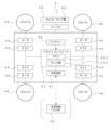
- the information processing system in this embodiment has a management server 1, one or more user terminals 2, one or more moving bodies 4 (e.g., flying bodies, running bodies, etc.), and one or more moving body storage devices 5.
- the management server 1, the user terminals 2, the moving bodies 4, and the moving body storage devices 5 are communicatively connected to each other via a network.
- the illustrated configuration is an example, and is not limited thereto.
- the configuration may be one in which the moving body storage device 5 is not included and the moving body is carried by the user.
- ⁇ Management Server 1> 2 is a diagram showing a hardware configuration of the management server 1. Note that the illustrated configuration is an example, and the management server 1 may have other configurations.
- the management server 1 is connected to a user terminal 2, a mobile object 4, and a mobile object storage device 5, and constitutes part of the system.
- the management server 1 may be a general-purpose computer such as a workstation or a personal computer, or may be logically realized by cloud computing.
- the management server 1 includes at least a processor 10, a memory 11, a storage 12, a transmission/reception unit 13, an input/output unit 14, etc., which are electrically connected to each other via a bus 15.
- the processor 10 is a computing device that controls the operation of the entire management server 1, controls the transmission and reception of data between each element, and performs information processing necessary for application execution and authentication processing.
- the processor 10 is a CPU (Central Processing Unit) and/or a GPU (Graphics Processing Unit), and executes programs for this system stored in the storage 12 and deployed in the memory 11 to perform various information processing operations.
- CPU Central Processing Unit
- GPU Graphics Processing Unit
- Memory 11 includes a main memory consisting of a volatile storage device such as DRAM (Dynamic Random Access Memory) and an auxiliary memory consisting of a non-volatile storage device such as a flash memory or HDD (Hard Disc Drive). Memory 11 is used as a work area for processor 10, and also stores the BIOS (Basic Input/Output System) that is executed when management server 1 is started, various setting information, etc.
- BIOS Basic Input/Output System
- Storage 12 stores various programs such as application programs.
- a database that stores data used for each process may be constructed in storage 12.
- the transmission/reception unit 13 connects the management server 1 to the network.
- the transmission/reception unit 13 may be equipped with a short-range communication interface for Bluetooth (registered trademark) and BLE (Bluetooth Low Energy).
- the input/output unit 14 includes information input devices such as a keyboard and mouse, and output devices such as a display.
- the bus 15 is commonly connected to each of the above elements and transmits, for example, address signals, data signals, and various control signals.
- ⁇ User Terminal 2> 3 also includes a processor 20, a memory 21, a storage 22, a transmission/reception unit 23, an input/output unit 24, etc., which are electrically connected to each other via a bus 25.
- the functions of each element can be configured in the same way as the management server 1 described above, so detailed explanations of each element will be omitted.
- the moving body 4 is a known moving body including an air vehicle such as a drone or an unmanned aerial vehicle, a running body such as an unmanned ground vehicle, etc., and is particularly a moving body that can be autonomously controlled. As a specific example of such a moving body, the moving body 4 will be described below.
- FIG. 4 is a block diagram showing a hardware configuration of the moving body 4.
- the flight controller 41 can have one or more processors such as a programmable processor (e.g., a central processing unit (CPU)).
- a programmable processor e.g., a central processing unit (CPU)
- Flight controller 41 also has and can access memory 411.
- Memory 411 stores logic, code, and/or program instructions that the flight controller can execute to perform one or more steps.
- Flight controller 41 may also include sensors 412, such as inertial sensors (accelerometers, gyro sensors), GPS sensors, proximity sensors (e.g., lidar), etc.
- the memory 411 may include, for example, a separable medium such as an SD card or random access memory (RAM) or an external storage device. Data acquired from the camera/sensors 42 may be directly transmitted to and stored in the memory 411. For example, still image/video data captured by a camera or the like may be recorded in an internal memory or an external memory, but is not limited to this, and may be recorded in at least one of the management server 1, the user terminal 2, or the mobile body storage device 5 from the camera/sensors 42 or the internal memory via the network NW.
- the camera 42 is installed on the mobile body 4 via a gimbal 43.
- the flight controller 41 includes a control module (not shown) configured to control the state of the moving object.
- the control module controls the propulsion mechanism (motor 45, etc.) of the moving object via an ESC 44 (Electric Speed Controller) in order to adjust the spatial arrangement, speed, and/or acceleration of the moving object having six degrees of freedom (translational motion x, y, and z , and rotational motion ⁇ x , ⁇ y , and ⁇ z ).
- the propeller 46 rotates by the motor 45 powered by a battery 48, thereby generating lift for the moving object.
- the control module can control one or more of the states of the mounted parts and sensors.
- the flight controller 41 can communicate with a transceiver 47 configured to transmit and/or receive data from one or more external devices (e.g., a transceiver 49, a terminal, a display device, or other remote control).
- a transceiver 49 can use any suitable communication means, such as wired or wireless communication.
- the transceiver unit 47 can utilize one or more of a local area network (LAN), a wide area network (WAN), infrared, wireless, WiFi, a point-to-point (P2P) network, a telecommunications network, cloud communications, etc.
- LAN local area network
- WAN wide area network
- P2P point-to-point
- the transmitter/receiver 47 can transmit and/or receive one or more of the following: data acquired by the sensors 42, processing results generated by the flight controller 41, specific control data, user commands from a terminal or a remote controller, etc.
- the sensors 42 may include an inertial sensor (acceleration sensor, gyro sensor), a GPS sensor, a proximity sensor (e.g., LiDAR (Light Detection And Ranging), etc.), or a vision/image sensor (e.g., a camera).
- the sensors 42 may also be referred to as "camera 42".
- the sensors 42 are configured to acquire, when an image is captured by the camera 42 as a vision/image sensor, information on the actual capturing position of the camera 42 in real space at the time the image was captured, the actual capturing direction which is the direction in real space to which the optical center axis of the camera 42 faces, the focal length and angle of view of the camera 42, and other capturing condition information in association with the image. Therefore, the image data of an image captured by the camera 42 according to this embodiment includes not only the image data, but also the above-mentioned capturing condition information linked thereto.
- ⁇ Management server functions> 5 is a block diagram illustrating functions implemented in the management server 1.
- the management server 1 has various functional units for executing a process of arranging a captured image in a corresponding three-dimensional model based on an image captured by a camera included in the sensors 42 of the mobile object 4 and image capture condition information associated therewith, and three-dimensional model data indicating the arrangement of components (e.g., walls, columns, stairs, equipment, etc.) within a structure (e.g., a building such as a building).
- the management server 1 includes a processor 10, a transmission/reception unit 13, and a storage unit 200.
- the processor 10 includes an actual shooting position information acquisition unit 110, a virtual distance generation unit 120, a size identification unit 130, an image projection unit 140, a difference detection unit 150, a shooting target identification unit 160, an image linking unit 170, and a movement execution unit 180.
- the storage unit 200 includes various databases, such as a three-dimensional data storage unit 210, a shooting image data storage unit 220, and a movement information storage unit 230.
- the three-dimensional data storage unit 210 stores three-dimensional model data showing the components inside and outside the structure and their positions.
- the three-dimensional model data may be any data as long as it is three-dimensional model data (more preferably three-dimensional model data having dimensional information) showing the arrangement of the components inside the structure, which is created based on data created with CAD (Computer-Aided Design) design software.
- CAD Computer-Aided Design
- it may be three-dimensional model data reconstructed from BIM (Building Information Modeling) data, CIM (Construction Information Modeling) data, CAD data, BIM data, etc., or it may be three-dimensional model data obtained by generating a component having a predetermined height based on two-dimensional design drawing data.
- the generation of the three-dimensional model data such as reconstruction may be executed by the processor 10 of the management server 1, or the management server 1 may acquire the three-dimensional model data generated by executing the process on an external device different from the management server 1.
- the three-dimensional model data showing the structure may be linked with information showing the type, size, scale, etc. of the structure.
- information on the three-dimensional model data for example, information showing a predetermined spatial area based on the three-dimensional model data (for example, a spatial area based on a structure such as the spatial area between pillar A and pillar B, or a spatial area defined by a three-dimensional coordinate system in which the three-dimensional model data is placed (particularly, a spatial area based on coordinates specified by a user operation)) may be stored in the three-dimensional data storage unit 210.
- the processor 10 of the management server 1 generates a virtual space represented by the three-dimensional model data in a three-dimensional coordinate system based on the three-dimensional model data stored in the three-dimensional data storage unit 210.
- the placement information of each three-dimensional model in the virtual space thus generated such as its placement position and orientation, is already known.
- the photographed image data storage unit 220 stores photographed image data captured by the sensors 42 of the moving object 4 and transmitted from the moving object 4 to the management server 1.
- the image data captured and acquired by the sensors 42 of the moving object 4 includes not only the image data, but also photographing condition information related to the actual photographing position in real space of the camera 42 at the time the image was captured, the actual photographing direction which is the direction in real space in which the optical center axis of the camera 42 faces, and the focal length of the camera 42, which are associated (linked) with the image. Therefore, the photographed image data stored in the photographed image data storage unit 220 includes image data and photographing condition information linked thereto.
- the photographing condition information may be metadata associated with the image data.
- the photographed image data stored in the photographed image data storage unit 220 may further include information on at least one of the photographed subject model present at the photographed subject position in the virtual space, identified by the photographed subject identification unit 160 of the processor 10 described below and linked to the image linking unit 170, or the photographed subject space. Details of the above-mentioned identification process and linking process by the photographed subject identification unit 160 and the image linking unit 170 will be described later. Furthermore, the photographed image data stored in the photographed image data storage unit 220 may be associated with information on the size of the image data at the photographed subject position, which is the position of the photographed subject in the virtual space, identified by the size identification unit 130 as described below.
- the movement information storage unit 230 stores movement information used for movement for the purpose of taking actual images of various objects inside and outside buildings, for example.
- the movement information includes, for example, movement route information (including waypoint information), movement speed, flight altitude, imaging conditions (imaging direction, imaging angle of view, imaging focal length, overlap rate of captured images, etc.), information acquired during movement (for example, image data and imaging condition information associated therewith, etc.), etc.
- the movement information can be generated, for example, by setting the parameters of various information included in the movement information on the management server 1 or the user terminal 2.
- the movement route may be generated by, for example, setting the position of the mobile body storage device 5 as the movement start position and the movement end position, and passing through each waypoint. Conversely, it may be configured such that, without the mobile body storage device 5, the position where the user carries the mobile body 4 is set as the movement start position (so-called home point), and the user retrieves the mobile body 4 at the movement end position (which may be back to the home point).
- it may be configured to generate a movement route including the position of the mobile body storage device 5 selected as the movement start position or movement end position based on the information of the mobile body storage device 5 managed by the management server 1 (for example, position information, storage state information, storage machine information, etc.).
- the actual shooting position information acquisition unit 110 acquires, as shooting condition information linked to the captured image data captured by the camera 42 of the moving body 4 and transmitted from the moving body 4 to the management server 1, in particular, actual shooting position information indicating the actual shooting position of the camera 42 in real space at the time the image was captured.
- the actual shooting position information acquisition unit 110 may further acquire information regarding the actual shooting direction, which is the direction in real space in which the optical center axis of the camera 42 faces, and the focal length and angle of view of the camera 42, from the above-mentioned shooting condition information linked to the acquired image data.
- the actual photographing position of the camera (sensors) 42 in real space is a position expressed in a three-dimensional coordinate system of real space. If the camera 42 of the moving body 4 includes a GNSS sensor (GPS sensor, etc.) and latitude and longitude information can be acquired by the GNSS sensor as position information of the sensors 42, the actual photographing position of the camera (sensors) 42 in real space may be expressed in latitude and longitude.
- GNSS sensor GPS sensor, etc.
- the actual photographing position of the camera (sensors) 42 in real space may be expressed as a position in a three-dimensional coordinate system with the origin being a reference position in real space (for example, the flight start position (home point) of the moving body 4).
- the processor 10 of the management server 1 When the processor 10 of the management server 1 generates a virtual space represented by the three-dimensional model data in a three-dimensional coordinate system based on the three-dimensional model data stored in the three-dimensional data storage unit 210, the processor 10 performs a process of constructing a correlation between the three-dimensional coordinate system of the real space and the three-dimensional coordinate system of the virtual space, for example by associating the three-dimensional coordinate system of the real space with the three-dimensional coordinate system of the virtual space.
- the processor 10 aligns and associates a reference position in the three-dimensional coordinate system of the real space (for example, the flight start position of the moving body 4) with a reference position in the three-dimensional coordinate system of the virtual space corresponding to that position, thereby constructing a correlation between the three-dimensional coordinate system of the real space and the three-dimensional coordinate system of the virtual space.
- This allows the processor 10 to convert and express the position in the three-dimensional coordinate system of the real space of the moving body 4 flying in the real space into the position in the three-dimensional coordinate system of the virtual moving body (a virtual object corresponding to the moving body 4 in the real space) in the virtual space. If the scale of the three-dimensional model data in the virtual space differs from the scale of the corresponding structure (composition) in the real space, the scale of the three-dimensional model data may be adjusted during alignment.
- the virtual distance generation unit 120 performs processing to generate virtual distance information indicating the virtual distance from a virtual shooting position corresponding to the real shooting position of the camera 42 in the real space to a shooting target position, which is the position of the shooting target in the virtual space, in the virtual space generated by the processor 10.
- the shooting target position in the virtual space may be, for example, coordinate information in the virtual space, the position of a three-dimensional model of the shooting target in the virtual space (virtual components such as walls, pillars, stairs, and equipment in a building in the virtual space), or any spatial region position in the virtual space.
- the virtual distance generation unit 120 performs a process of calculating a virtual distance, which is the distance from the virtual shooting position to the shooting target position, based on a virtual shooting position in the virtual space in the three-dimensional coordinate system of the virtual space and the shooting target position (the position of the three-dimensional model corresponding to the component of the shooting target), and generating virtual distance information.
- the virtual distance which is the distance from the virtual shooting position to the shooting target position
- the virtual distance can be obtained by determining the length of a line segment connecting the virtual shooting position and the shooting target position in the three-dimensional coordinate system of the virtual space along the shooting direction (particularly the optical axis direction).
- the size determination unit 130 performs processing to determine the size of the image data at the position of the subject to be photographed, which is the position of the subject to be photographed in the virtual space, based on the angle of view information and focal length information of the camera 42, which is the photographing condition information included in the photographed image data acquired when the camera 42 photographs an image, and the virtual distance information generated by the virtual distance generation unit 120.
- the size determination unit 130 determines the size of the image data at the position of the subject to be photographed.
- the size determination unit 130 uses the angle of view information and focal length information of the camera 42 linked to the captured image data to calculate the size of a first plane (the "near plane" of the viewing frustum shown in FIG. 6) that is a focal length n away from the virtual capture position C in the virtual space that corresponds to the actual capture position of the camera 42.
- the size of the first plane corresponds to the size of the captured image data of the subject captured by the camera 42.
- the size determination unit 130 uses the size of the first plane calculated as described above, the focal length information, and the virtual distance information generated by the virtual distance generation unit 120 to calculate the size of the image data in a second plane (the "far plane" of the viewing frustum shown in FIG. 6) that is a virtual distance f away from the virtual shooting position C.
- the size of the second plane is the size of the first plane enlarged according to the ratio of the focal length n and the virtual distance f, and is the size of the image data at the shooting target position.
- the size determination unit 130 calculates the size of the image data at the shooting target position as described above, making it possible to obtain the actual size of the component in real space corresponding to the three-dimensional model at the shooting target position from the size of that image data.
- the image projection unit 140 performs a process of projecting image data of the size specified by the size specification unit 130 onto the subject model, which is a three-dimensional model of the subject that exists at the subject position in the virtual space.
- the subject model which is a three-dimensional model of the subject that exists at the subject position in the virtual space.
- the difference detection unit 150 performs processing to detect the difference in shape between the subject shown in the image data projected by the image projection unit 140 into the virtual space and the subject model corresponding to that subject.
- the difference detection unit 150 extracts characteristic parts of the object to be photographed that appear in the projected image data (e.g., the outline of the cupboard that is the object to be photographed and the corners where the outlines intersect) and characteristic parts of the object to be photographed that appear in the object to be photographed onto which the image data is projected that correspond to the characteristic parts of the object to be photographed (e.g., the ridges of the object to be photographed that is a three-dimensional model of the cupboard and the corners where the ridges intersect), and detects the difference in shape or position between the object to be photographed that appears in the projected image data and the object to be photographed model based on the positional relationship between these characteristic parts.
- characteristic parts of the object to be photographed that appear in the projected image data e.g., the outline of the cupboard that is the object to be photographed and the corners where the outlines intersect
- characteristic parts of the object to be photographed that appear in the object to be photographed onto which the image data is projected that correspond to the characteristic parts of the object to be photographed (e.g., the ridges of
- the difference information obtained as a result of the detection process by the difference detection unit 150 can be used, for example, to correct the position, shape, size, etc. of the image data that the image projection unit 140 projects in the virtual space, and to position the image data so that it is appropriately superimposed on the object to be photographed model.
- the subject identification unit 160 performs processing to identify at least either the subject model present at the subject position in the virtual space or the subject space based on the center position of the angle of view of the camera 42 when the camera 42 captured the captured image data.
- the shooting target identification unit 160 first obtains a virtual shooting direction in the virtual space corresponding to the actual shooting direction of the camera 42 based on information on the actual shooting direction, which is the direction in real space to which the optical center axis of the camera 42 faces at the time the shooting image data was captured, among the shooting condition information acquired when the camera 42 captured the shooting image data and linked to the shooting image data.
- the virtual shooting direction in the virtual space can be expressed as a virtual straight line extending from a virtual shooting position in the virtual space corresponding to the actual shooting position of the camera 42 to the virtual shooting direction corresponding to the actual shooting direction of the camera 42.
- the center position of the angle of view of the camera 42 can correspond to the virtual shooting position in the virtual space.
- the shooting target identification unit 160 then identifies a shooting target model or shooting target space that exists at a shooting target position in the virtual space, where a virtual straight line extending in the virtual shooting direction from a virtual shooting position in the virtual space corresponding to the actual shooting position of the camera 42 intersects.
- the photographing subject identification unit 160 identifies at least one of the photographing subject model or the photographing subject space that exists at the photographing subject position in the virtual space, based on the center position of the angle of view of the camera 42 when the camera 42 captured the photographed image data.
- the image linking unit 170 links the image data to at least one of the subject model or the subject space identified by the subject identification unit 160 and stores the image data in the storage unit 200. More specifically, based on the identification information acquired as a result of the identification process by the subject identification unit 160, the image linking unit 170 associates the photographed image data captured by the camera 42 with the subject model or the subject space in the virtual space that corresponds to the subject in real space reflected in the photographed image data, and stores the photographed image data linked to the corresponding subject model or subject space in the virtual space in the photographed image data storage unit 220 of the storage unit 200.
- the movement execution unit 180 executes the movement of the moving body 4 for the purpose of taking real images of various shooting subjects inside and outside the building, etc., based on various movement information stored in the movement information storage unit 230.
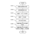
- Fig. 7 is a flowchart illustrating the information processing method according to this embodiment.
- the actual shooting position information acquisition unit 110 in the information processing system of this embodiment acquires shooting condition information linked to the captured image data from the captured image data captured by the camera 42 of the mobile body 4 and transmitted from the mobile body 4 to the management server 1 (step S101).
- the shooting condition information is acquired when the camera (sensors) 42 serving as a vision/image sensor captures an image, and includes information about the actual shooting position of the camera 42 in real space at the time the image was captured, the actual shooting direction which is the direction in real space to which the optical center axis of the camera 42 faces, the focal length and angle of view of the camera 42, etc., and is associated with the captured image data which is the data of the captured image.
- the actual shooting position information acquisition unit 110 particularly acquires information about the actual shooting position of the camera 42 in real space at the time the image was captured from the captured image data.
- the virtual distance generation unit 120 in the information processing system generates virtual distance information indicating the virtual distance from the virtual shooting position corresponding to the real shooting position of the camera 42 in the real space to the shooting target position, which is the position of the shooting target in the virtual space, in the virtual space generated by the processor 10 (step S102).
- the virtual distance generation unit 120 can obtain the virtual distance to the shooting target position, which is the position of the shooting target in the virtual space, by calculating the length of the line segment connecting the virtual shooting position in the virtual space and the shooting target position (the position of the three-dimensional model corresponding to the component of the shooting target) in the three-dimensional coordinate system of the virtual space.
- the size determination unit 130 in the information processing system determines the size of the image data at the position of the subject to be photographed in the virtual space based on the angle of view information and focal length information of the camera 42, which are included in the photographing condition information contained in the photographed image data acquired when the camera 42 photographed the image, and the virtual distance information generated by the virtual distance generation unit 120 (step S103).
- the size determination unit 130 calculates the size of a first plane (the "near plane" of the viewing frustum shown in FIG. 6) that is a focal distance away from the virtual shooting position in the virtual space corresponding to the actual shooting position of the camera 42, and then uses the size of the first plane, the focal distance, and the virtual distance to calculate the size of a second plane that is a virtual distance away from the virtual shooting position, thereby determining the size of the image data at the shooting target position in the virtual space.
- a first plane the "near plane" of the viewing frustum shown in FIG. 6
- the image data by determining the size of the image data at the position of the subject in the virtual space, when the captured image data is projected at the position of the subject in later processing (the position of the three-dimensional model corresponding to the component of the subject), it is possible to make the image data a size appropriate for the position of the subject. Furthermore, if the three-dimensional model data includes dimensional information and scale information, it is possible to obtain the actual size of the component in real space corresponding to the three-dimensional model at the position of the subject from the size of the image data.
- the image projection unit 140 in the information processing system projects image data of the size specified by the size specification unit 130 onto the subject model, which is a three-dimensional model of the subject that exists at the subject position in the virtual space (step S104).
- the subject model which is a three-dimensional model of the subject that exists at the subject position in the virtual space.
- the difference detection unit 150 in the information processing system detects the difference in shape between the subject shown in the image data projected by the image projection unit 140 into the virtual space and the subject model corresponding to that subject (step S105).
- the difference detection unit 150 extracts characteristic parts of the object to be photographed that are reflected in the projected image data and corresponding characteristic parts of the object to be photographed that are projected onto the image data, and detects the difference in shape or position between the object to be photographed that are reflected in the projected image data and the object to be photographed model based on the positional relationship between these characteristic parts.
- the difference information thus obtained for example, it becomes possible to correct the position, shape, size, etc. of the image data that the image projection unit 140 projects in the virtual space, and to arrange the image data so that it is appropriately superimposed on the object to be photographed model.
- the imaging subject identification unit 160 in the information processing system identifies at least one of the imaging subject model present at the imaging subject position in the virtual space or the imaging subject space based on the center position of the angle of view of the camera 42 when the camera 42 captured the captured image data (step S106).
- the shooting subject identification unit 160 first determines a virtual shooting direction in the virtual space corresponding to the actual shooting direction of the camera 42 based on information about the actual shooting direction, which is the direction in real space in which the optical center axis of the camera 42 faces at the time the captured image data was captured, and then identifies the shooting subject model or shooting subject space that exists at the shooting subject position in the virtual space, where a virtual straight line extending from the virtual shooting position in the virtual space corresponding to the actual shooting position of the camera 42 in the virtual space intersects with the virtual shooting direction.
- the image linking unit 170 in the information processing system links the image data to at least one of the subject model or subject space identified by the subject identification unit 160 and stores the image data in the storage unit 200 (step S107).
- This makes it possible, for example, to search for the subject model or subject space corresponding to the image data stored in the photographed image data storage unit 220, or to search for image data corresponding to the subject model or subject space stored in the three-dimensional data storage unit 210, and enables the image projection unit 140 to automatically identify the image data to be projected at the subject position in step S104.
- an information processing system or the like that can easily manage images captured by a moving body 4 in association with the position and size of the subject to be captured.
- the information processing method according to this embodiment includes identifying the size of image data at the position of the subject to be captured in virtual space, so that when the captured image data is projected onto the position of the subject to be captured (the position of the three-dimensional model corresponding to the constituent feature of the subject to be captured), the image data can be sized to suit the position of the subject to be captured, and further, if the three-dimensional model data includes dimensional information and scale information, it is possible to obtain the actual size of the constituent feature in real space corresponding to the three-dimensional model at the position of the subject to be captured from the size of the image data.
- the mobile object 4 may further include devices, equipment, etc. that are used to inspect the interior and/or exterior walls of the structure for the presence or absence of specific events. More specifically, any device necessary to know the state of the structure being inspected may be employed, such as an imaging device (visible light camera, infrared camera, metal detector, ultrasonic measuring device, etc.), a keystroke device, etc., a detection device (metal detector), a sound collection device, an odor measuring device, a gas detector, an air pollution measuring device, a detection device (a device for detecting cosmic rays, radiation, electromagnetic waves, etc.), etc.
- an imaging device visible light camera, infrared camera, metal detector, ultrasonic measuring device, etc.
- a keystroke device etc.
- a detection device metal detector
- a sound collection device such as an odor measuring device, a gas detector, an air pollution measuring device, a detection device (a device for detecting cosmic rays, radiation, electromagnetic waves, etc.), etc.
- the information processing method according to this embodiment may be executed, for example, during security or surveillance within a structure, and may further include devices, equipment, etc. used for security or surveillance. More specifically, any device necessary for capturing images and detecting abnormalities or intruders in the structure to be guarded or monitored, such as an imaging device (visible light camera, infrared camera, night vision camera, metal detector, ultrasonic measuring device, etc.) or a sensor device (motion sensor, infrared sensor, etc.), may be employed.
- an imaging device visible light camera, infrared camera, night vision camera, metal detector, ultrasonic measuring device, etc.
- a sensor device motion sensor, infrared sensor, etc.
- the mobile object 4 can be suitably used as a mobile object for photography equipped with a camera or the like, and can also be used in various industries such as security, infrastructure monitoring, surveying, inspection of buildings and structures such as sports venues, factories, and warehouses, and disaster response.
Landscapes
- Engineering & Computer Science (AREA)
- Theoretical Computer Science (AREA)
- Multimedia (AREA)
- Signal Processing (AREA)
- Physics & Mathematics (AREA)
- General Physics & Mathematics (AREA)
- Computer Vision & Pattern Recognition (AREA)
- Computer Graphics (AREA)
- Computer Hardware Design (AREA)
- General Engineering & Computer Science (AREA)
- Software Systems (AREA)
- Processing Or Creating Images (AREA)
- Studio Devices (AREA)
- Image Analysis (AREA)
Abstract
Description
本発明は、情報処理システム及び情報処理方法に関する。 The present invention relates to an information processing system and an information processing method.
従来、(Drone)や無人航空機(UAV:Unmanned Aerial Vehicle)などの飛行体(以下、「飛行体」と総称する)や無人地上車両(UGV:Unmanned Ground Vehicle)などの走行体などの自律制御可能な移動体が産業に利用され始めており、とりわけ、そのような移動体により建物の屋内外を点検することが行われている。特許文献1には、移動体により屋内を点検してその画像を管理するシステムが開示されている。
Traditionally, autonomously controllable mobile objects, such as flying objects (hereinafter collectively referred to as "flying objects") such as drones and unmanned aerial vehicles (UAVs) and mobile objects such as unmanned ground vehicles (UGVs), have begun to be used in industry, and in particular, such mobile objects are used to inspect the interior and exterior of buildings.
しかしながら、特許文献1の開示技術においては、移動体により撮影された画像が、建物のどの位置をどの方向から撮影した画像であるか不明であり、さらには、撮影対象の物体の実際の現場におけるサイズを画像から知ることも難しい。そのため、移動体により撮影された画像を撮影対象位置と関連付けて管理することが困難である。
However, with the technology disclosed in
また、撮影された画像を3次元モデルに貼り付けることで実際の現場を模した仮想空間を生成することが可能であるが、上記のように撮影対象の物体の実際の現場におけるサイズが不明であると、撮影された画像を3次元モデル上にどの程度のサイズで貼り付けるかが不明である。そのため、作業者が画像編集システム等を用いて撮影された画像のサイズや3次元モデル上の貼り付け位置を手作業で調節して貼り付け作業を行う必要があり、特に多数の画像を3次元モデルに貼り付ける場合に作業者の負担が大きくなる。 It is also possible to generate a virtual space that mimics an actual site by pasting a captured image onto a three-dimensional model, but if the size of the object being photographed at the actual site is unknown as described above, it is unclear at what size the captured image should be pasted onto the three-dimensional model. This requires the worker to manually adjust the size of the captured image and the pasting position on the three-dimensional model using an image editing system or the like, which places a heavy burden on the worker, especially when pasting a large number of images onto a three-dimensional model.
本発明はこのような背景を鑑みてなされたものであり、移動体により撮影された画像を撮影対象位置及びそのサイズと関連付けて容易に管理することが可能な情報処理システム等を提供することを目的とする。 The present invention was made in consideration of this background, and aims to provide an information processing system etc. that can easily manage images captured by a moving object by associating them with the position and size of the object being captured.
上記課題を解決するための本発明の主たる発明は、取得した撮影画像データに紐づく実空間内の実撮影位置を示す実撮影位置情報を取得する実撮影位置情報取得部と、仮想空間内において、実撮影位置に対応する仮想撮影位置から撮影対象位置までの仮想距離を示す仮想距離情報を生成する仮想距離生成部と、撮影画像データを撮影した際の画角情報及び焦点距離情報と仮想距離情報に基づき、撮影対象位置における画像データのサイズを特定するサイズ特定部と、を備える情報処理システムである。 The main invention of the present invention for solving the above problem is an information processing system that includes an actual shooting position information acquisition unit that acquires actual shooting position information indicating an actual shooting position in real space linked to the acquired captured image data, a virtual distance generation unit that generates virtual distance information indicating a virtual distance from a virtual shooting position corresponding to the actual shooting position to a shooting target position in a virtual space, and a size determination unit that determines the size of the image data at the shooting target position based on the angle of view information, focal length information, and virtual distance information when the captured image data was captured.
本発明によれば、特に、移動体により撮影された画像を撮影対象位置及びそのサイズと関連付けて容易に管理することが可能な情報処理システム等を提供することができる。 The present invention can provide an information processing system that can easily manage images captured by a moving object by associating them with the location and size of the object being captured.
本発明の実施形態の内容を列記して説明する。本発明の実施の形態による情報処理システム等は、以下のような構成を備える。
[項目1]
取得した撮影画像データに紐づく実空間内の実撮影位置を示す実撮影位置情報を取得する実撮影位置情報取得部と、
仮想空間内において、前記実撮影位置に対応する仮想撮影位置から撮影対象位置までの仮想距離を示す仮想距離情報を生成する仮想距離生成部と、
前記撮影画像データを撮影した際の画角情報及び焦点距離情報と前記仮想距離情報に基づき、前記撮影対象位置における前記画像データのサイズを特定するサイズ特定部と、
を備える情報処理システム。
[項目2]
前記仮想空間内の前記撮影対象位置に存在する撮影対象モデル上に、特定した前記サイズの前記画像データを投影する画像投影部をさらに備える、
項目1に記載の情報処理システム。
[項目3]
投影した前記画像データに映る撮影対象物と、前記撮影対象モデルとの形状の差分を検出する差分検出部をさらに備える、
項目2に記載の情報処理システム。
[項目4]
前記撮影画像データを撮影した際の前記画角の中心位置に基づき、前記仮想空間内の前記撮影対象位置に存在する撮影対象モデル、または、撮影対象空間の少なくともいずれかを特定する撮影対象特定部をさらに備える、
項目1に記載の情報処理システム。
[項目5]
前記撮影対象特定部により特定された前記撮影対象モデルまたは撮影対象空間の少なくともいずれかに紐付けて、前記画像データを記憶させる画像紐付部をさらに備える、
項目4に記載の情報処理システム。
[項目6]
取得した撮影画像データに紐づく実空間内の実撮影位置を示す実撮影位置情報を取得するステップと、
仮想空間内において、前記実撮影位置に対応する仮想撮影位置から撮影対象位置までの仮想距離を示す仮想距離情報を生成するステップと、
前記撮影画像データを撮影した際の画角情報及び焦点距離情報と前記仮想距離情報に基づき、前記撮影対象位置における前記画像データのサイズを特定するステップと、
を含む、コンピュータにより実行される情報処理方法。
[項目7]
取得した撮影画像データに紐づく実空間内の実撮影位置を示す実撮影位置情報を取得するステップと、
仮想空間内において、前記実撮影位置に対応する仮想撮影位置から撮影対象位置までの仮想距離を示す仮想距離情報を生成するステップと、
前記撮影画像データを撮影した際の画角情報及び焦点距離情報と前記仮想距離情報に基づき、前記撮影対象位置における前記画像データのサイズを特定するステップと、
をコンピュータにより実行させるプログラム。
The contents of the embodiment of the present invention will be listed and described below. An information processing system according to the embodiment of the present invention has the following configuration.
[Item 1]
an actual photography position information acquisition unit that acquires actual photography position information indicating an actual photography position in a real space associated with the acquired photographed image data;
a virtual distance generating unit that generates virtual distance information indicating a virtual distance from a virtual shooting position corresponding to the actual shooting position to a shooting target position in a virtual space;
a size determination unit that determines a size of the image data at the position of the subject to be photographed based on information on an angle of view and focal length when the photographed image data was photographed and on the virtual distance information;
An information processing system comprising:
[Item 2]
An image projection unit projects the image data of the specified size onto a shooting target model present at the shooting target position in the virtual space.
[Item 3]
Further comprising a difference detection unit that detects a difference in shape between the object to be photographed shown in the projected image data and the object to be photographed model.
3. The information processing system according to
[Item 4]
and a shooting target specifying unit that specifies at least one of a shooting target model present at the shooting target position in the virtual space and a shooting target space based on a center position of the angle of view when the captured image data is captured.
[Item 5]
An image linking unit that links the image data to at least one of the shooting target model or the shooting target space identified by the shooting target identification unit and stores the image data.
5. An information processing system according to
[Item 6]
acquiring real photographing position information indicating a real photographing position in a real space associated with the acquired photographed image data;
generating virtual distance information indicating a virtual distance from a virtual shooting position corresponding to the real shooting position to a shooting target position in a virtual space;
specifying a size of the image data at the position of the subject to be photographed based on information on an angle of view and focal length when the photographed image data was photographed and on the virtual distance information;
2. An information processing method implemented by a computer, comprising:
[Item 7]
acquiring real photographing position information indicating a real photographing position in a real space associated with the acquired photographed image data;
generating virtual distance information indicating a virtual distance from a virtual shooting position corresponding to the real shooting position to a shooting target position in a virtual space;
specifying a size of the image data at the position of the subject to be photographed based on information on an angle of view and focal length when the photographed image data was photographed and on the virtual distance information;
A program that causes a computer to execute the above.
<実施の形態の詳細>
以下、本発明の実施の形態による情報処理システム等について説明する。添付図面において、同一または類似の要素には同一または類似の参照符号及び名称が付され、各実施形態の説明において同一または類似の要素に関する重複する説明は省略することがある。また、各実施形態で示される特徴は、互いに矛盾しない限り他の実施形態にも適用可能である。
<Details of the embodiment>
Hereinafter, an information processing system according to an embodiment of the present invention will be described. In the accompanying drawings, identical or similar elements are given identical or similar reference symbols and names, and duplicated descriptions of identical or similar elements may be omitted in the description of each embodiment. Furthermore, features shown in each embodiment can be applied to other embodiments as long as they are not mutually inconsistent.
<構成>
図1に示されるように、本実施の形態における情報処理システムは、管理サーバ1と、一以上のユーザ端末2と、一以上の移動体4(例えば、飛行体や走行体など)と、一以上の移動体格納装置5とを有している。管理サーバ1と、ユーザ端末2と、移動体4と、移動体格納装置5は、ネットワークを介して互いに通信可能に接続されている。なお、図示された構成は一例であり、これに限らず、例えば、移動体格納装置5を有さずに、ユーザにより持ち運びされる構成などでもよい。
<Configuration>
As shown in Fig. 1, the information processing system in this embodiment has a
<管理サーバ1>
図2は、管理サーバ1のハードウェア構成を示す図である。なお、図示された構成は一例であり、これ以外の構成を有していてもよい。
<
2 is a diagram showing a hardware configuration of the
図示されるように、管理サーバ1は、ユーザ端末2と、移動体4、移動体格納装置5と接続され本システムの一部を構成する。管理サーバ1は、例えばワークステーションやパーソナルコンピュータのような汎用コンピュータとしてもよいし、或いはクラウド・コンピューティングによって論理的に実現されてもよい。
As shown in the figure, the
管理サーバ1は、少なくとも、プロセッサ10、メモリ11、ストレージ12、送受信部13、入出力部14等を備え、これらはバス15を通じて相互に電気的に接続される。
The
プロセッサ10は、管理サーバ1全体の動作を制御し、各要素間におけるデータの送受信の制御、及びアプリケーションの実行及び認証処理に必要な情報処理等を行う演算装置である。例えばプロセッサ10はCPU(Central Processing Unit)および/またはGPU(Graphics Processing Unit)であり、ストレージ12に格納されメモリ11に展開された本システムのためのプログラム等を実行して各情報処理を実施する。
The processor 10 is a computing device that controls the operation of the
メモリ11は、DRAM(Dynamic Random Access Memory)等の揮発性記憶装置で構成される主記憶と、フラッシュメモリやHDD(Hard Disc Drive)等の不揮発性記憶装置で構成される補助記憶と、を含む。メモリ11は、プロセッサ10のワークエリア等として使用され、また、管理サーバ1の起動時に実行されるBIOS(Basic Input / Output System)、及び各種設定情報等を格納する。
Memory 11 includes a main memory consisting of a volatile storage device such as DRAM (Dynamic Random Access Memory) and an auxiliary memory consisting of a non-volatile storage device such as a flash memory or HDD (Hard Disc Drive). Memory 11 is used as a work area for processor 10, and also stores the BIOS (Basic Input/Output System) that is executed when
ストレージ12は、アプリケーション・プログラム等の各種プログラムを格納する。各処理に用いられるデータを格納したデータベースがストレージ12に構築されていてもよい。 Storage 12 stores various programs such as application programs. A database that stores data used for each process may be constructed in storage 12.
送受信部13は、管理サーバ1をネットワークに接続する。なお、送受信部13は、Bluetooth(登録商標)及びBLE(Bluetooth Low Energy)の近距離通信インターフェースを備えていてもよい。
The transmission/reception unit 13 connects the
入出力部14は、キーボード・マウス類等の情報入力機器、及びディスプレイ等の出力機器である。 The input/output unit 14 includes information input devices such as a keyboard and mouse, and output devices such as a display.
バス15は、上記各要素に共通に接続され、例えば、アドレス信号、データ信号及び各種制御信号を伝達する。 The bus 15 is commonly connected to each of the above elements and transmits, for example, address signals, data signals, and various control signals.
<ユーザ端末2>
図3に示されるユーザ端末2もまた、プロセッサ20、メモリ21、ストレージ22、送受信部23、入出力部24等を備え、これらはバス25を通じて相互に電気的に接続される。各要素の機能は、上述した管理サーバ1と同様に構成することが可能であることから、各要素の詳細な説明は省略する。
<
3 also includes a processor 20, a memory 21, a storage 22, a transmission/reception unit 23, an input/output unit 24, etc., which are electrically connected to each other via a bus 25. The functions of each element can be configured in the same way as the
<移動体4>
移動体4は、ドローンや無人航空機などの飛行体や無人地上車両などの走行体などを含む既知の移動体であって、特に自律制御可能な移動体である。このような移動体の具体的な例として、移動体4を例示して以下で説明する。図4は、移動体4のハードウェア構成を示すブロック図である。フライトコントローラ41は、プログラマブルプロセッサ(例えば、中央演算処理装置(CPU))などの1つ以上のプロセッサを有することができる。
<
The moving
また、フライトコントローラ41は、メモリ411を有しており、当該メモリにアクセス可能である。メモリ411は、1つ以上のステップを行うためにフライトコントローラが実行可能であるロジック、コード、および/またはプログラム命令を記憶している。また、フライトコントローラ41は、慣性センサ(加速度センサ、ジャイロセンサ)、GPSセンサ、近接センサ(例えば、ライダー)等のセンサ412を含みうる。 Flight controller 41 also has and can access memory 411. Memory 411 stores logic, code, and/or program instructions that the flight controller can execute to perform one or more steps. Flight controller 41 may also include sensors 412, such as inertial sensors (accelerometers, gyro sensors), GPS sensors, proximity sensors (e.g., lidar), etc.
メモリ411は、例えば、SDカードやランダムアクセスメモリ(RAM)などの分離可能な媒体または外部の記憶装置を含んでいてもよい。カメラ/センサ類42から取得したデータは、メモリ411に直接に伝達されかつ記憶されてもよい。例えば、カメラ等で撮影した静止画・動画データが内蔵メモリ又は外部メモリに記録されてもよいが、これに限らず、カメラ/センサ類42または内蔵メモリからネットワークNWを介して、少なくとも管理サーバ1やユーザ端末2、移動体格納装置5のいずれかに1つに記録されてもよい。カメラ42は移動体4にジンバル43を介して設置される。
The memory 411 may include, for example, a separable medium such as an SD card or random access memory (RAM) or an external storage device. Data acquired from the camera/sensors 42 may be directly transmitted to and stored in the memory 411. For example, still image/video data captured by a camera or the like may be recorded in an internal memory or an external memory, but is not limited to this, and may be recorded in at least one of the
フライトコントローラ41は、移動体の状態を制御するように構成された図示しない制御モジュールを含んでいる。例えば、制御モジュールは、6自由度(並進運動x、y及びz、並びに回転運動θx、θy及びθz)を有する移動体の空間的配置、速度、および/または加速度を調整するために、ESC44(Electric Speed Controller)を経由して移動体の推進機構(モータ45等)を制御する。バッテリー48から給電されるモータ45によりプロペラ46が回転することで移動体の揚力を生じさせる。制御モジュールは、搭載部、センサ類の状態のうちの1つ以上を制御することができる。
The flight controller 41 includes a control module (not shown) configured to control the state of the moving object. For example, the control module controls the propulsion mechanism (
フライトコントローラ41は、1つ以上の外部のデバイス(例えば、送受信機(プロポ)49、端末、表示装置、または他の遠隔の制御器)からのデータを送信および/または受け取るように構成された送受信部47と通信可能である。送受信機49は、有線通信または無線通信などの任意の適当な通信手段を使用することができる。
The flight controller 41 can communicate with a
例えば、送受信部47は、ローカルエリアネットワーク(LAN)、ワイドエリアネットワーク(WAN)、赤外線、無線、WiFi、ポイントツーポイント(P2P)ネットワーク、電気通信ネットワーク、クラウド通信などのうちの1つ以上を利用することができる。
For example, the
送受信部47は、センサ類42で取得したデータ、フライトコントローラ41が生成した処理結果、所定の制御データ、端末または遠隔の制御器からのユーザコマンドなどのうちの1つ以上を送信および/または受け取ることができる。
The transmitter/
本実施の形態によるセンサ類42は、慣性センサ(加速度センサ、ジャイロセンサ)、GPSセンサ、近接センサ(例えば、LiDAR(Light Detection And Ranging)等)、またはビジョン/イメージセンサ(例えば、カメラ)を含み得る。以下、センサ類42を「カメラ42」と称することもある。本実施の形態によるセンサ類42は、ビジョン/イメージセンサしてのカメラ42で画像を撮影する際に、その画像を撮影した時点におけるカメラ42の実空間における実撮影位置、カメラ42の光学中心軸が向く実空間における方向である実撮影方向、カメラ42の焦点距離及び画角等に関する撮影条件情報を当該画像に関連付けて取得するように構成されている。したがって、本実施の形態によるカメラ42によって撮影された画像の画像データには、当該画像のデータのみならず、上記のような撮影条件情報が紐づけられて含まれる。 The sensors 42 according to this embodiment may include an inertial sensor (acceleration sensor, gyro sensor), a GPS sensor, a proximity sensor (e.g., LiDAR (Light Detection And Ranging), etc.), or a vision/image sensor (e.g., a camera). Hereinafter, the sensors 42 may also be referred to as "camera 42". The sensors 42 according to this embodiment are configured to acquire, when an image is captured by the camera 42 as a vision/image sensor, information on the actual capturing position of the camera 42 in real space at the time the image was captured, the actual capturing direction which is the direction in real space to which the optical center axis of the camera 42 faces, the focal length and angle of view of the camera 42, and other capturing condition information in association with the image. Therefore, the image data of an image captured by the camera 42 according to this embodiment includes not only the image data, but also the above-mentioned capturing condition information linked thereto.
<管理サーバの機能>
図5は、管理サーバ1に実装される機能を例示したブロック図である。本発明の実施の形態においては、管理サーバ1は、移動体4のセンサ類42に含まれるカメラで撮影された画像及びこれに関連付けられた撮影条件情報と、構造物(例えばビルなどの建物)内の構成物(例えば、壁、柱、階段、設備など)の配置を示す三次元モデルデータとに基づき、撮影された画像を対応する三次元モデルに配置する処理を実行するための各種機能部を有している。
<Management server functions>
5 is a block diagram illustrating functions implemented in the
本実施の形態においては、管理サーバ1は、プロセッサ10、送受信部13、記憶部200を備えている。プロセッサ10は、実撮影位置情報取得部110、仮想距離生成部120、サイズ特定部130、画像投影部140、差分検出部150、撮影対象特定部160、画像紐付部170及び移動実行部180を備えている。また、記憶部200は、三次元データ記憶部210、撮影画像データ記憶部220、移動情報記憶部230の各種データベースを含む。
In this embodiment, the
最初に記憶部200の各種データベースについて説明すると、三次元データ記憶部210には、構造物内外の構成物及びその配置位置を示す三次元モデルデータが記憶されている。三次元モデルデータは、CAD(Computer―Aided Design)設計ソフトウェアで作成されたデータを基にして作成された、構造物内の構成物の配置を示す三次元モデルデータ(より好ましくは寸法情報を有する三次元モデルデータ)であればどのようなデータであってもよく、例えば、BIM(Building Information Modeling)データ、CIM(Construction Information Modeling)データ、CADデータ、BIMデータ等から再構築された三次元モデルデータなどであってもよいし、二次元の設計図データに基づき所定の高さを有する構成物を生成することで得られた三次元モデルデータであってもよい。再構築等の三次元モデルデータの生成は管理サーバ1のプロセッサ10により実行されてもよいし、あるいは、管理サーバ1とは異なる外部装置で実行されて生成された三次元モデルデータを管理サーバ1が取得してもよい。また、構成物を示す三次元モデルデータについては、構成物の種別やサイズ、縮尺などを示す情報を紐づけられていてもよい。その他、三次元モデルデータに関する情報として、例えば三次元モデルデータを基準とした所定の空間領域(例えば、柱Aと柱Bの間の空間領域というような構成物を基準とした空間領域や、三次元モデルデータが配置される三次元座標系で規定される空間領域(特に、ユーザ操作により指定された座標を基準とした空間領域))を示す情報を三次元データ記憶部210に記憶してもよい。
First, the various databases of the storage unit 200 are described. The three-dimensional
管理サーバ1のプロセッサ10は、三次元データ記憶部210に記憶された三次元モデルデータに基づいて、三次元モデルデータが三次元座標系で表現する仮想空間を生成する。このように生成された仮想空間内における各々の三次元モデルの配置位置及び配置向き等の配置情報は既知である。
The processor 10 of the
撮影画像データ記憶部220は、移動体4のセンサ類42によって撮影され、移動体4から管理サーバ1に送信された撮影画像データを記憶する。上述したように、移動体4のセンサ類42によって撮影されて取得された画像データには、当該画像のデータだけでなく、画像を撮影した時点におけるカメラ42の実空間における実撮影位置、カメラ42の光学中心軸が向く実空間における方向である実撮影方向及びカメラ42の焦点距離等に関する撮影条件情報が当該画像に関連付けて(紐づけられて)含まれている。したがって、撮影画像データ記憶部220に記憶される撮影画像データは、画像データとそれに紐づけられた撮影条件情報とを含む。撮影画像データにおいて、撮影条件情報は画像データに関連付けられたメタデータであってもよい。
The photographed image
撮影画像データ記憶部220に記憶される撮影画像データはさらに、後述するプロセッサ10の撮影対象特定部160によって特定されて画像紐付部170に紐付けられた、仮想空間内の撮影対象位置に存在する撮影対象モデル、または、撮影対象空間の少なくともいずれかに関する情報を含んでいてもよい。撮影対象特定部160及び画像紐付部170による上記の特定処理及び紐付け処理の詳細については後述する。さらには、撮影画像データ記憶部220に記憶される撮影画像データは、後述するようにサイズ特定部130によって特定された、仮想空間内における撮影対象の位置である撮影対象位置における画像データのサイズに関する情報が関連付けられてもよい。
The photographed image data stored in the photographed image
移動情報記憶部230は、例えば建造物の内外の各種撮影対象物の実画像の撮影等を目的とする移動において用いられる移動情報を記憶している。移動情報は、例えば、移動経路情報(ウェイポイント情報を含む)、移動速度、飛行高度、撮像条件(撮影方向、撮像画角、撮像焦点距離、撮像画像のオーバーラップ率など)、移動時取得情報(例えば、画像データ及びこれに関連付けられた撮影条件情報等)などを含む。
The movement
移動情報は、例えば、移動情報に含まれる各種情報のパラメータを管理サーバ1又はユーザ端末2上で設定することにより生成することができる。なお、移動経路としては、例えば、移動体格納装置5の位置を移動開始位置及び移動終了位置として、各ウェイポイントを通過する移動経路を生成するようにしてもよいし、逆に移動体格納装置5を有さずに、ユーザにより移動体4を持ち運びされた位置を移動開始位置(いわゆるホームポイント)としたり、移動終了位置(ホームポイントに戻ってもよい)においてユーザが移動体4を回収したりする構成などでもよいし、管理サーバ1により管理された移動体格納装置5の情報(例えば、位置情報や格納状態情報、格納機情報など)を基に、移動開始位置または移動終了位置として選択された移動体格納装置5の位置も含めた移動経路として生成される構成でもよい。
The movement information can be generated, for example, by setting the parameters of various information included in the movement information on the
次にプロセッサ10の各機能部について説明すると、実撮影位置情報取得部110は、移動体4のカメラ42によって撮影され移動体4から管理サーバ1に送信された撮影画像データに紐づけられている撮影条件情報として、特に、画像を撮影した時点におけるカメラ42の実空間における実撮影位置を示す実撮影位置情報を取得する。実撮影位置情報取得部110はさらに、取得した画像データに紐づけられている上記の撮影条件情報から、カメラ42の光学中心軸が向く実空間における方向である実撮影方向とカメラ42の焦点距離及び画角とに関する情報を取得してもよい。
Next, the functional units of the processor 10 will be described. The actual shooting position information acquisition unit 110 acquires, as shooting condition information linked to the captured image data captured by the camera 42 of the moving
カメラ(センサ類)42の実空間における実撮影位置は、実空間の三次元座標系で表現される位置である。移動体4のカメラ42がGNSSセンサ(GPSセンサ等)を含み、センサ類42の位置情報としてGNSSセンサで緯度・経度情報を取得可能な場合は、カメラ(センサ類)42の実空間における実撮影位置は緯度・経度で表現されてもよい。あるいは、センサ類42の位置情報を慣性センサ(加速度センサ、ジャイロセンサ)等の非GNSSセンサで取得する場合は、カメラ(センサ類)42の実空間における実撮影位置は、実空間における基準位置(例えば、移動体4の飛行開始位置(ホームポイント))を原点とする三次元座標系における位置で表現されてもよい。
The actual photographing position of the camera (sensors) 42 in real space is a position expressed in a three-dimensional coordinate system of real space. If the camera 42 of the moving
管理サーバ1のプロセッサ10は、三次元データ記憶部210に記憶された三次元モデルデータに基づいて、三次元モデルデータが三次元座標系で表現する仮想空間を生成する際に、例えば実空間の三次元座標系と仮想空間の三次元座標系とを対応付けることにより、実空間の三次元座標系と仮想空間の三次元座標系との相関関係を構築する処理を行う。一例として、プロセッサ10は、実空間の三次元座標系における基準位置(例えば、移動体4の飛行開始位置)と、その位置に対応する仮想空間の三次元座標系における基準位置とを位置合わせして対応付けることにより、実空間の三次元座標系と仮想空間の三次元座標系との相関関係を構築する。これにより、プロセッサ10は、実空間内で飛行する移動体4の実空間の三次元座標系における位置を、仮想空間内の仮想移動体(実空間の移動体4に対応する仮想物体)の三次元座標系における位置に変換して表現することが可能である。なお、仮想空間における三次元モデルデータの縮尺が実空間における対応する構造物(構成物)の縮尺と異なる場合は、位置合わせに伴って三次元モデルデータの縮尺を調整してもよい。
When the processor 10 of the
このように、実空間の三次元座標系と仮想空間の三次元座標系との相関関係を構築することにより、例えばユーザ端末2上に表示される仮想空間の三次元座標系をベースにウェイポイントを設定した場合においても、実空間の移動体4の三次元座標系に基づく移動経路生成などの位置指定が可能となる。三次元モデルデータが寸法情報を備える場合には、仮想空間の三次元座標系を基準として、例えば10m真っすぐ飛んで右に曲がる、といったような現実の縮尺を用いた移動経路生成が可能となる。
In this way, by constructing a correlation between the three-dimensional coordinate system of the real space and the three-dimensional coordinate system of the virtual space, it becomes possible to specify positions such as generating a movement path based on the three-dimensional coordinate system of the moving
仮想距離生成部120は、プロセッサ10が生成した仮想空間内において、カメラ42の実空間における実撮影位置に対応する仮想撮影位置から、仮想空間内における撮影対象の位置である撮影対象位置までの仮想距離を示す仮想距離情報を生成する処理を行う。仮想空間内における撮影対象位置は、例えば、仮想空間内の座標情報、仮想空間内の撮影対象の三次元モデル(仮想空間内の建物内の壁、柱、階段、設備などの仮想構成物)の位置や、仮想空間内の任意の空間領域位置であってもよい。 The virtual distance generation unit 120 performs processing to generate virtual distance information indicating the virtual distance from a virtual shooting position corresponding to the real shooting position of the camera 42 in the real space to a shooting target position, which is the position of the shooting target in the virtual space, in the virtual space generated by the processor 10. The shooting target position in the virtual space may be, for example, coordinate information in the virtual space, the position of a three-dimensional model of the shooting target in the virtual space (virtual components such as walls, pillars, stairs, and equipment in a building in the virtual space), or any spatial region position in the virtual space.
仮想距離生成部120は、仮想空間の三次元座標系における仮想空間内の仮想撮影位置と、撮影対象位置(撮影対象の構成物に対応する三次元モデルの位置)とに基づいて、仮想撮影位置から撮影対象位置までの距離である仮想距離を算出して、仮想距離情報を生成する処理を行う。仮想撮影位置から撮影対象位置までの距離である仮想距離は、一例として、仮想空間の三次元座標系における仮想撮影位置と撮影対象位置とを撮影方向(特に光軸方向)に沿って結ぶ線分の長さを求めることで取得することが可能である。 The virtual distance generation unit 120 performs a process of calculating a virtual distance, which is the distance from the virtual shooting position to the shooting target position, based on a virtual shooting position in the virtual space in the three-dimensional coordinate system of the virtual space and the shooting target position (the position of the three-dimensional model corresponding to the component of the shooting target), and generating virtual distance information. As an example, the virtual distance, which is the distance from the virtual shooting position to the shooting target position, can be obtained by determining the length of a line segment connecting the virtual shooting position and the shooting target position in the three-dimensional coordinate system of the virtual space along the shooting direction (particularly the optical axis direction).
サイズ特定部130は、カメラ42が画像を撮影したときに取得した撮影画像データに含まれる撮影条件情報であるカメラ42の画角情報及び焦点距離情報と、仮想距離生成部120が生成した仮想距離情報とに基づき、仮想空間内における撮影対象の位置である撮影対象位置における画像データのサイズを特定する処理を行う。 The size determination unit 130 performs processing to determine the size of the image data at the position of the subject to be photographed, which is the position of the subject to be photographed in the virtual space, based on the angle of view information and focal length information of the camera 42, which is the photographing condition information included in the photographed image data acquired when the camera 42 photographs an image, and the virtual distance information generated by the virtual distance generation unit 120.
ここで、図6を参照して、サイズ特定部130が撮影対象位置における画像データのサイズを特定する処理の一例について説明する。 Now, with reference to FIG. 6, an example of the process in which the size determination unit 130 determines the size of the image data at the position of the subject to be photographed will be described.
サイズ特定部130はまず、撮影画像データに紐づけられたカメラ42の画角情報及び焦点距離情報を用いて、カメラ42の実撮影位置に対応する仮想空間における仮想撮影位置Cから焦点距離nだけ離れた第1の平面(図6に示す視錐台の「near plane」)のサイズを算出する。第1の平面のサイズは、カメラ42が取得した撮影対象の撮影画像データのサイズに対応する。 First, the size determination unit 130 uses the angle of view information and focal length information of the camera 42 linked to the captured image data to calculate the size of a first plane (the "near plane" of the viewing frustum shown in FIG. 6) that is a focal length n away from the virtual capture position C in the virtual space that corresponds to the actual capture position of the camera 42. The size of the first plane corresponds to the size of the captured image data of the subject captured by the camera 42.
サイズ特定部130は次に、上記のように算出した第1の平面のサイズと、焦点距離情報及び仮想距離生成部120が生成した仮想距離情報とを用いて、仮想撮影位置Cから仮想距離fだけ離れた第2の平面(図6に示す視錐台の「far plane」)における画像データのサイズを算出する。第2の平面のサイズは、第1の平面のサイズを焦点距離nと仮想距離fとの比に応じて拡大した大きさであり、撮影対象位置における画像データのサイズである。三次元モデルデータが寸法情報及び縮尺情報を備える場合には、サイズ特定部130によって上記のように撮影対象位置における画像データのサイズを算出することで、撮影対象位置における三次元モデルに対応する実空間の構成物の実寸サイズをその画像データのサイズから取得することが可能となる。 The size determination unit 130 then uses the size of the first plane calculated as described above, the focal length information, and the virtual distance information generated by the virtual distance generation unit 120 to calculate the size of the image data in a second plane (the "far plane" of the viewing frustum shown in FIG. 6) that is a virtual distance f away from the virtual shooting position C. The size of the second plane is the size of the first plane enlarged according to the ratio of the focal length n and the virtual distance f, and is the size of the image data at the shooting target position. When the three-dimensional model data includes dimensional information and scale information, the size determination unit 130 calculates the size of the image data at the shooting target position as described above, making it possible to obtain the actual size of the component in real space corresponding to the three-dimensional model at the shooting target position from the size of that image data.
画像投影部140は、仮想空間内の撮影対象位置に存在する撮影対象の三次元モデルである撮影対象モデル上に、サイズ特定部130が特定したサイズの画像データを投影する処理を行う。この処理により、撮影対象位置に存在する撮影対象の三次元モデルである撮影対象モデル上の対応する位置に、その撮影対象モデルに対応する実空間の構成物の画像が撮影対象モデルの大きさに合致するサイズで貼り付けられ、撮影対象モデルの表面に実空間の構成物(撮影対象物)のテクスチャが付与される。 The image projection unit 140 performs a process of projecting image data of the size specified by the size specification unit 130 onto the subject model, which is a three-dimensional model of the subject that exists at the subject position in the virtual space. Through this process, an image of a real-space component that corresponds to the subject model is pasted at a size that matches the size of the subject model at the corresponding position on the subject model, which is a three-dimensional model of the subject that exists at the subject position, and the texture of the real-space component (subject) is added to the surface of the subject model.
差分検出部150は、画像投影部140が仮想空間内において投影した画像データに映る撮影対象物と、その撮影対象物に対応する撮影対象モデルとの形状の差分を検出する処理を行う。 The difference detection unit 150 performs processing to detect the difference in shape between the subject shown in the image data projected by the image projection unit 140 into the virtual space and the subject model corresponding to that subject.
差分検出処理の一例として撮影対象物が略直方体形状の戸棚である例を挙げて説明すると、差分検出部150は、投影した画像データに映る撮影対象物における特徴部位(例えば、撮影対象物である戸棚の外形線や外形線同士が交差する隅の部分など)と、画像データが投影された撮影対象モデルにおける、撮影対象物の特徴部位に対応する特徴部位(例えば、戸棚の三次元モデルである撮影対象モデルの稜線や稜線同士が交差する隅の部分など)とを抽出し、それらの特徴部位同士の位置関係に基づいて、投影した画像データに映る撮影対象物と撮影対象モデルとの形状あるいは配置位置の差分を検出する。差分検出部150による検出処理の結果取得された差分情報は、例えば、画像投影部140が仮想空間内で投影する画像データの位置、形状、大きさ等を補正して、画像データを撮影対象モデル上に適切に重なるように配置することに用いることができる。 As an example of the difference detection process, let us take an example in which the object to be photographed is a cupboard having a substantially rectangular parallelepiped shape. The difference detection unit 150 extracts characteristic parts of the object to be photographed that appear in the projected image data (e.g., the outline of the cupboard that is the object to be photographed and the corners where the outlines intersect) and characteristic parts of the object to be photographed that appear in the object to be photographed onto which the image data is projected that correspond to the characteristic parts of the object to be photographed (e.g., the ridges of the object to be photographed that is a three-dimensional model of the cupboard and the corners where the ridges intersect), and detects the difference in shape or position between the object to be photographed that appears in the projected image data and the object to be photographed model based on the positional relationship between these characteristic parts. The difference information obtained as a result of the detection process by the difference detection unit 150 can be used, for example, to correct the position, shape, size, etc. of the image data that the image projection unit 140 projects in the virtual space, and to position the image data so that it is appropriately superimposed on the object to be photographed model.
撮影対象特定部160は、カメラ42が撮影画像データを撮影した際のカメラ42の画角の中心位置に基づき、仮想空間内の撮影対象位置に存在する撮影対象モデル、または、撮影対象空間の少なくともいずれかを特定する処理を行う。 The subject identification unit 160 performs processing to identify at least either the subject model present at the subject position in the virtual space or the subject space based on the center position of the angle of view of the camera 42 when the camera 42 captured the captured image data.
より具体的には、撮影対象特定部160はまず、カメラ42が撮影画像データを撮影した際に取得され、その撮影画像データに紐づけられた撮影条件情報のうち、その撮影画像データを撮影した時点におけるカメラ42の光学中心軸が向く実空間における方向である実撮影方向に関する情報に基づき、カメラ42の実撮影方向に対応する仮想空間における仮想撮影方向を求める。仮想空間における仮想撮影方向は、カメラ42の実撮影位置に対応する仮想空間における仮想撮影位置から、カメラ42の実撮影方向に対応する仮想撮影方向に延びる仮想的な直線で表現され得る。カメラ42の画角の中心位置は、仮想空間における仮想撮影位置に対応しうる。撮影対象特定部160は次に、カメラ42の実撮影位置に対応する仮想空間における仮想撮影位置から仮想撮影方向に延びる仮想的な直線が交差する、仮想空間内の撮影対象位置に存在する撮影対象モデルまたは撮影対象空間を特定する。 More specifically, the shooting target identification unit 160 first obtains a virtual shooting direction in the virtual space corresponding to the actual shooting direction of the camera 42 based on information on the actual shooting direction, which is the direction in real space to which the optical center axis of the camera 42 faces at the time the shooting image data was captured, among the shooting condition information acquired when the camera 42 captured the shooting image data and linked to the shooting image data. The virtual shooting direction in the virtual space can be expressed as a virtual straight line extending from a virtual shooting position in the virtual space corresponding to the actual shooting position of the camera 42 to the virtual shooting direction corresponding to the actual shooting direction of the camera 42. The center position of the angle of view of the camera 42 can correspond to the virtual shooting position in the virtual space. The shooting target identification unit 160 then identifies a shooting target model or shooting target space that exists at a shooting target position in the virtual space, where a virtual straight line extending in the virtual shooting direction from a virtual shooting position in the virtual space corresponding to the actual shooting position of the camera 42 intersects.
撮影対象特定部160はこのような処理により、カメラ42が撮影画像データを撮影した際のカメラ42の画角の中心位置に基づき、仮想空間内の撮影対象位置に存在する撮影対象モデルまたは撮影対象空間の少なくともいずれかを特定する。 By performing this type of processing, the photographing subject identification unit 160 identifies at least one of the photographing subject model or the photographing subject space that exists at the photographing subject position in the virtual space, based on the center position of the angle of view of the camera 42 when the camera 42 captured the photographed image data.
画像紐付部170は、撮影対象特定部160により特定された撮影対象モデルまたは撮影対象空間の少なくともいずれかに紐付けて、画像データを記憶部200に記憶させる処理を行う。より具体的には、画像紐付部170は、撮影対象特定部160による特定処理の結果取得された特定情報に基づき、カメラ42が撮影した撮影画像データに、その撮影画像データに映る実空間の撮影対象物に対応する仮想空間内の撮影対象モデルまたは撮影対象空間を関連付けて、対応する仮想空間内の撮影対象モデルまたは撮影対象空間が紐づけられた撮影画像データを記憶部200の撮影画像データ記憶部220に記憶させる。
The image linking unit 170 links the image data to at least one of the subject model or the subject space identified by the subject identification unit 160 and stores the image data in the storage unit 200. More specifically, based on the identification information acquired as a result of the identification process by the subject identification unit 160, the image linking unit 170 associates the photographed image data captured by the camera 42 with the subject model or the subject space in the virtual space that corresponds to the subject in real space reflected in the photographed image data, and stores the photographed image data linked to the corresponding subject model or subject space in the virtual space in the photographed image
移動実行部180は、移動情報記憶部230に記憶された各種移動情報に基づき、建造物の内外の各種撮影対象物の実画像の撮影等を目的とする移動体4の移動を実行する。
The movement execution unit 180 executes the movement of the moving
<本実施形態にかかる情報処理方法の一例>
次に、図7を参照して、本実施形態にかかる情報処理方法(特に、三次元モデル上における画像データサイズの特定方法)について説明する。図7は、本実施形態にかかる情報処理方法を例示するフローチャートである。
<An example of an information processing method according to this embodiment>
Next, an information processing method according to this embodiment (particularly, a method for specifying the size of image data on a three-dimensional model) will be described with reference to Fig. 7. Fig. 7 is a flowchart illustrating the information processing method according to this embodiment.
最初に、本実施形態の情報処理システムにおける実撮影位置情報取得部110は、移動体4のカメラ42によって撮影され移動体4から管理サーバ1に送信された撮影画像データから、その撮影画像データに紐づけられている撮影条件情報を取得する(ステップS101)。
First, the actual shooting position information acquisition unit 110 in the information processing system of this embodiment acquires shooting condition information linked to the captured image data from the captured image data captured by the camera 42 of the
撮影条件情報は、ビジョン/イメージセンサしてのカメラ(センサ類)42が画像を撮影する際に併せて取得される、その画像を撮影した時点におけるカメラ42の実空間における実撮影位置、カメラ42の光学中心軸が向く実空間における方向である実撮影方向、カメラ42の焦点距離及び画角等に関する情報を含み、撮影した画像のデータである撮影画像データに関連付けられている。ステップS101の処理において、実撮影位置情報取得部110は特に、画像を撮影した時点におけるカメラ42の実空間における実撮影位置に関する情報をその撮影画像データから取得する。 The shooting condition information is acquired when the camera (sensors) 42 serving as a vision/image sensor captures an image, and includes information about the actual shooting position of the camera 42 in real space at the time the image was captured, the actual shooting direction which is the direction in real space to which the optical center axis of the camera 42 faces, the focal length and angle of view of the camera 42, etc., and is associated with the captured image data which is the data of the captured image. In the processing of step S101, the actual shooting position information acquisition unit 110 particularly acquires information about the actual shooting position of the camera 42 in real space at the time the image was captured from the captured image data.
次に、情報処理システムにおける仮想距離生成部120は、プロセッサ10が生成した仮想空間内において、カメラ42の実空間における実撮影位置に対応する仮想撮影位置から、仮想空間内における撮影対象の位置である撮影対象位置までの仮想距離を示す仮想距離情報を生成する(ステップS102)。一例として、仮想距離生成部120は、仮想空間の三次元座標系における仮想空間内の仮想撮影位置と撮影対象位置(撮影対象の構成物に対応する三次元モデルの位置)とを結ぶ線分の長さを求めることで、仮想空間内における撮影対象の位置である撮影対象位置までの仮想距離を取得することが可能である。 Next, the virtual distance generation unit 120 in the information processing system generates virtual distance information indicating the virtual distance from the virtual shooting position corresponding to the real shooting position of the camera 42 in the real space to the shooting target position, which is the position of the shooting target in the virtual space, in the virtual space generated by the processor 10 (step S102). As an example, the virtual distance generation unit 120 can obtain the virtual distance to the shooting target position, which is the position of the shooting target in the virtual space, by calculating the length of the line segment connecting the virtual shooting position in the virtual space and the shooting target position (the position of the three-dimensional model corresponding to the component of the shooting target) in the three-dimensional coordinate system of the virtual space.
次に、情報処理システムにおけるサイズ特定部130は、カメラ42が画像を撮影したときに取得した撮影画像データに含まれる撮影条件情報のうちのカメラ42の画角情報及び焦点距離情報と、仮想距離生成部120が生成した仮想距離情報とに基づき、仮想空間内の撮影対象位置における画像データのサイズを特定する(ステップS103)。 Next, the size determination unit 130 in the information processing system determines the size of the image data at the position of the subject to be photographed in the virtual space based on the angle of view information and focal length information of the camera 42, which are included in the photographing condition information contained in the photographed image data acquired when the camera 42 photographed the image, and the virtual distance information generated by the virtual distance generation unit 120 (step S103).
サイズ特定部130は、一例として図6を参照して説明したように、カメラ42の実撮影位置に対応する仮想空間における仮想撮影位置から焦点距離だけ離れた第1の平面(図6に示す視錐台の「near plane」)のサイズを算出し、次に第1の平面のサイズと焦点距離及び仮想距離とを用いて仮想撮影位置から仮想距離だけ離れた第2の平面のサイズを算出することによって、仮想空間内における撮影対象位置における画像データのサイズを特定する。 As explained with reference to FIG. 6 as an example, the size determination unit 130 calculates the size of a first plane (the "near plane" of the viewing frustum shown in FIG. 6) that is a focal distance away from the virtual shooting position in the virtual space corresponding to the actual shooting position of the camera 42, and then uses the size of the first plane, the focal distance, and the virtual distance to calculate the size of a second plane that is a virtual distance away from the virtual shooting position, thereby determining the size of the image data at the shooting target position in the virtual space.
このように、仮想空間の撮影対象位置における画像データのサイズを特定することにより、後の処理において撮影画像データを撮影対象位置(撮影対象の構成物に対応する三次元モデルの位置)に投影するときに、画像データを撮影対象位置に適応したサイズとすることが可能となる。さらには、三次元モデルデータが寸法情報及び縮尺情報を備える場合には、撮影対象位置における三次元モデルに対応する実空間の構成物の実寸サイズをその画像データのサイズから取得することが可能となる。 In this way, by determining the size of the image data at the position of the subject in the virtual space, when the captured image data is projected at the position of the subject in later processing (the position of the three-dimensional model corresponding to the component of the subject), it is possible to make the image data a size appropriate for the position of the subject. Furthermore, if the three-dimensional model data includes dimensional information and scale information, it is possible to obtain the actual size of the component in real space corresponding to the three-dimensional model at the position of the subject from the size of the image data.
次に、情報処理システムにおける画像投影部140は、仮想空間内の撮影対象位置に存在する撮影対象の三次元モデルである撮影対象モデル上に、サイズ特定部130が特定したサイズの画像データを投影する(ステップS104)。これにより、撮影対象位置に存在する撮影対象の撮影対象モデル上に、その撮影対象モデルに対応する実空間の構成物の画像が撮影対象モデルの大きさに合致するサイズで貼り付けられ、撮影対象モデルの表面に実空間の構成物(撮影対象物)のテクスチャが付与される。 Next, the image projection unit 140 in the information processing system projects image data of the size specified by the size specification unit 130 onto the subject model, which is a three-dimensional model of the subject that exists at the subject position in the virtual space (step S104). As a result, an image of the real-space component that corresponds to the subject model of the subject that exists at the subject position is pasted onto the subject model of the subject that exists at the subject position at a size that matches the size of the subject model, and the texture of the real-space component (subject) is added to the surface of the subject model.
次に、情報処理システムにおける差分検出部150は、画像投影部140が仮想空間内において投影した画像データに映る撮影対象物と、その撮影対象物に対応する撮影対象モデルとの形状の差分を検出する(ステップS105)。
差分検出部150は、一例として、投影した画像データに映る撮影対象物における特徴部位と、画像データが投影された撮影対象モデルにおける対応する特徴部位とを抽出し、それらの特徴部位同士の位置関係に基づいて、投影した画像データに映る撮影対象物と撮影対象モデルとの形状あるいは配置位置の差分を検出する。このように取得された差分情報を用いることにより、例えば、画像投影部140が仮想空間内で投影する画像データの位置、形状、大きさ等を補正して、画像データを撮影対象モデル上に適切に重なるように配置することが可能となる。
Next, the difference detection unit 150 in the information processing system detects the difference in shape between the subject shown in the image data projected by the image projection unit 140 into the virtual space and the subject model corresponding to that subject (step S105).
As an example, the difference detection unit 150 extracts characteristic parts of the object to be photographed that are reflected in the projected image data and corresponding characteristic parts of the object to be photographed that are projected onto the image data, and detects the difference in shape or position between the object to be photographed that are reflected in the projected image data and the object to be photographed model based on the positional relationship between these characteristic parts. By using the difference information thus obtained, for example, it becomes possible to correct the position, shape, size, etc. of the image data that the image projection unit 140 projects in the virtual space, and to arrange the image data so that it is appropriately superimposed on the object to be photographed model.
次に、情報処理システムにおける撮影対象特定部160は、カメラ42が撮影画像データを撮影した際のカメラ42の画角の中心位置に基づき、仮想空間内の撮影対象位置に存在する撮影対象モデル、または、撮影対象空間の少なくともいずれかを特定する(ステップS106)。 Next, the imaging subject identification unit 160 in the information processing system identifies at least one of the imaging subject model present at the imaging subject position in the virtual space or the imaging subject space based on the center position of the angle of view of the camera 42 when the camera 42 captured the captured image data (step S106).
ステップS106の処理において、撮影対象特定部160はまず、撮影画像データを撮影した時点におけるカメラ42の光学中心軸が向く実空間における方向である実撮影方向に関する情報に基づき、カメラ42の実撮影方向に対応する仮想空間における仮想撮影方向を求め、次に、カメラ42の実撮影位置に対応する仮想空間における仮想撮影位置から仮想撮影方向に延びる仮想的な直線が交差する、仮想空間内の撮影対象位置に存在する撮影対象モデルまたは撮影対象空間を特定する。 In the processing of step S106, the shooting subject identification unit 160 first determines a virtual shooting direction in the virtual space corresponding to the actual shooting direction of the camera 42 based on information about the actual shooting direction, which is the direction in real space in which the optical center axis of the camera 42 faces at the time the captured image data was captured, and then identifies the shooting subject model or shooting subject space that exists at the shooting subject position in the virtual space, where a virtual straight line extending from the virtual shooting position in the virtual space corresponding to the actual shooting position of the camera 42 in the virtual space intersects with the virtual shooting direction.
最後に、情報処理システムにおける画像紐付部170は、撮影対象特定部160により特定された撮影対象モデルまたは撮影対象空間の少なくともいずれかに紐付けて、画像データを記憶部200に記憶させる(ステップS107)。これにより、例えば、撮影画像データ記憶部220に記憶されている画像データに対応する撮影対象モデルまたは撮影対象空間を検索したり、あるいは、三次元データ記憶部210に記憶されている撮影対象モデルまたは撮影対象空間に対応する画像データを検索することが可能となり、ステップS104において画像投影部140が撮影対象位置に投影すべき画像データを自動的に特定することが可能となる。
Finally, the image linking unit 170 in the information processing system links the image data to at least one of the subject model or subject space identified by the subject identification unit 160 and stores the image data in the storage unit 200 (step S107). This makes it possible, for example, to search for the subject model or subject space corresponding to the image data stored in the photographed image
このように、本実施形態によれば、移動体4により撮影された画像を撮影対象位置及びそのサイズと関連付けて容易に管理することが可能な情報処理システム等が提供される。特に、本実施形態にかかる情報処理方法は、仮想空間の撮影対象位置における画像データのサイズを特定することを含むことにより、撮影画像データを撮影対象位置(撮影対象の構成物に対応する三次元モデルの位置)に投影するときに、画像データを撮影対象位置に適応したサイズとすることが可能となり、さらには、三次元モデルデータが寸法情報及び縮尺情報を備える場合には、撮影対象位置における三次元モデルに対応する実空間の構成物の実寸サイズをその画像データのサイズから取得することが可能となる。
In this way, according to this embodiment, an information processing system or the like is provided that can easily manage images captured by a moving
移動体4は、構造物の内壁および/または外壁の所定の事象の有無を点検するために利用される装置、機器等をさらに備えていてもよい。より具体的には、撮像装置(可視光カメラ、赤外線カメラ、金属探知機、超音波測定器等)や、打鍵装置等、探知装置(金属探知機)、集音装置、臭気測定器、ガス検知器、空気汚染測定器、検出装置(宇宙線、放射線、電磁波等を検出するための装置)等の点検対象構造物の状態を知るために必要な装置は全て採用され得る。
The
また、本実施形態にかかる情報処理方法は例えば構造物内の警備や監視の際に実行されてもよく、警備や監視のために利用される装置、機器等をさらに備えていてもよい。より具体的には、撮像装置(可視光カメラ、赤外線カメラ、暗視カメラ、金属探知機、超音波測定器等)や、センサ装置(モーションセンサ、赤外線センサ等)等、警備・監視対象構造物の異常や侵入者等を撮像・検知するために必要な装置は全て採用され得る。 The information processing method according to this embodiment may be executed, for example, during security or surveillance within a structure, and may further include devices, equipment, etc. used for security or surveillance. More specifically, any device necessary for capturing images and detecting abnormalities or intruders in the structure to be guarded or monitored, such as an imaging device (visible light camera, infrared camera, night vision camera, metal detector, ultrasonic measuring device, etc.) or a sensor device (motion sensor, infrared sensor, etc.), may be employed.
さらに、移動体4は、カメラ等を搭載した撮影用の移動体としても好適に使用することができる他、セキュリティ分野、インフラ監視、測量、スポーツ会場・工場・倉庫等の建物や構造物内の点検、災害対応等の様々な産業にも利用することができる。
Furthermore, the
上述した実施の形態は、本発明の理解を容易にするための例示に過ぎず、本発明を限定して解釈するためのものではない。本発明は、その趣旨を逸脱することなく、変更、改良することができると共に、本発明にはその均等物が含まれることは言うまでもない。 The above-described embodiment is merely an example to facilitate understanding of the present invention, and is not intended to limit the interpretation of the present invention. The present invention can be modified and improved without departing from the spirit of the invention, and it goes without saying that the present invention includes equivalents.
1 管理サーバ
2 ユーザ端末
4 移動体
5 移動体格納装置
Claims (7)
仮想空間内において、前記実撮影位置に対応する仮想撮影位置から撮影対象位置までの仮想距離を示す仮想距離情報を生成する仮想距離生成部と、
前記撮影画像データを撮影した際の画角情報及び焦点距離情報と前記仮想距離情報に基づき、前記撮影対象位置における前記画像データのサイズを特定するサイズ特定部と、
を備える情報処理システム。 an actual photography position information acquisition unit that acquires actual photography position information indicating an actual photography position in a real space associated with the acquired photographed image data;
a virtual distance generating unit that generates virtual distance information indicating a virtual distance from a virtual shooting position corresponding to the actual shooting position to a shooting target position in a virtual space;
a size determination unit that determines a size of the image data at the position of the subject to be photographed based on information on an angle of view and focal length when the photographed image data was photographed and on the virtual distance information;
An information processing system comprising:
請求項1に記載の情報処理システム。 An image projection unit projects the image data of the specified size onto a shooting target model present at the shooting target position in the virtual space.
The information processing system according to claim 1 .
請求項2に記載の情報処理システム。 Further comprising a difference detection unit that detects a difference in shape between the object to be photographed shown in the projected image data and the object to be photographed model.
The information processing system according to claim 2 .
請求項1に記載の情報処理システム。 and a shooting target specifying unit that specifies at least one of a shooting target model present at the shooting target position in the virtual space and a shooting target space based on a center position of the angle of view when the captured image data is captured.
The information processing system according to claim 1 .
請求項4に記載の情報処理システム。 An image linking unit that links the image data to at least one of the shooting target model or the shooting target space identified by the shooting target identification unit and stores the image data.
5. The information processing system according to claim 4.
仮想空間内において、前記実撮影位置に対応する仮想撮影位置から撮影対象位置までの仮想距離を示す仮想距離情報を生成するステップと、
前記撮影画像データを撮影した際の画角情報及び焦点距離情報と前記仮想距離情報に基づき、前記撮影対象位置における前記画像データのサイズを特定するステップと、
を含む、コンピュータにより実行される情報処理方法。 acquiring real photographing position information indicating a real photographing position in a real space associated with the acquired photographed image data;
generating virtual distance information indicating a virtual distance from a virtual shooting position corresponding to the real shooting position to a shooting target position in a virtual space;
specifying a size of the image data at the position of the subject to be photographed based on information on an angle of view and focal length when the photographed image data was photographed and on the virtual distance information;
2. An information processing method implemented by a computer, comprising:
仮想空間内において、前記実撮影位置に対応する仮想撮影位置から撮影対象位置までの仮想距離を示す仮想距離情報を生成するステップと、
前記撮影画像データを撮影した際の画角情報及び焦点距離情報と前記仮想距離情報に基づき、前記撮影対象位置における前記画像データのサイズを特定するステップと、
をコンピュータにより実行させるプログラム。
acquiring real photographing position information indicating a real photographing position in a real space associated with the acquired photographed image data;
generating virtual distance information indicating a virtual distance from a virtual shooting position corresponding to the real shooting position to a shooting target position in a virtual space;
specifying a size of the image data at the position of the subject to be photographed based on information on an angle of view and focal length when the photographed image data was photographed and on the virtual distance information;
A program that causes a computer to execute the above.
Priority Applications (3)
| Application Number | Priority Date | Filing Date | Title |
|---|---|---|---|
| PCT/JP2023/021232 WO2024252585A1 (en) | 2023-06-07 | 2023-06-07 | Information processing system and information processing method |
| JP2023571627A JP7441579B1 (en) | 2023-06-07 | 2023-06-07 | Information processing system and information processing method |
| JP2024018628A JP2024177053A (en) | 2023-06-07 | 2024-02-09 | Information processing system and information processing method |
Applications Claiming Priority (1)
| Application Number | Priority Date | Filing Date | Title |
|---|---|---|---|
| PCT/JP2023/021232 WO2024252585A1 (en) | 2023-06-07 | 2023-06-07 | Information processing system and information processing method |
Publications (1)
| Publication Number | Publication Date |
|---|---|
| WO2024252585A1 true WO2024252585A1 (en) | 2024-12-12 |
Family
ID=90038501
Family Applications (1)
| Application Number | Title | Priority Date | Filing Date |
|---|---|---|---|
| PCT/JP2023/021232 Ceased WO2024252585A1 (en) | 2023-06-07 | 2023-06-07 | Information processing system and information processing method |
Country Status (2)
| Country | Link |
|---|---|
| JP (2) | JP7441579B1 (en) |
| WO (1) | WO2024252585A1 (en) |
Families Citing this family (1)
| Publication number | Priority date | Publication date | Assignee | Title |
|---|---|---|---|---|
| JP7696129B1 (en) * | 2024-11-05 | 2025-06-20 | 株式会社センシンロボティクス | Information processing system, information processing method, and program |
Citations (5)
| Publication number | Priority date | Publication date | Assignee | Title |
|---|---|---|---|---|
| JP2003006680A (en) * | 2001-06-20 | 2003-01-10 | Zenrin Co Ltd | Method of generating 3D electronic map data |
| JP2005339127A (en) * | 2004-05-26 | 2005-12-08 | Olympus Corp | Apparatus and method for displaying image information |
| JP2021103410A (en) * | 2019-12-25 | 2021-07-15 | セコム株式会社 | Mobile body and imaging system |
| JP2022507502A (en) * | 2018-11-15 | 2022-01-18 | イーディーエックス テクノロジーズ インコーポレイテッド | Augmented Reality (AR) Imprint Method and System |
| KR20220031975A (en) * | 2020-09-06 | 2022-03-15 | 주식회사 태울코리아 | Spatial analysis method using cctv image range in 3d space |
-
2023
- 2023-06-07 JP JP2023571627A patent/JP7441579B1/en active Active
- 2023-06-07 WO PCT/JP2023/021232 patent/WO2024252585A1/en not_active Ceased
-
2024
- 2024-02-09 JP JP2024018628A patent/JP2024177053A/en active Pending
Patent Citations (5)
| Publication number | Priority date | Publication date | Assignee | Title |
|---|---|---|---|---|
| JP2003006680A (en) * | 2001-06-20 | 2003-01-10 | Zenrin Co Ltd | Method of generating 3D electronic map data |
| JP2005339127A (en) * | 2004-05-26 | 2005-12-08 | Olympus Corp | Apparatus and method for displaying image information |
| JP2022507502A (en) * | 2018-11-15 | 2022-01-18 | イーディーエックス テクノロジーズ インコーポレイテッド | Augmented Reality (AR) Imprint Method and System |
| JP2021103410A (en) * | 2019-12-25 | 2021-07-15 | セコム株式会社 | Mobile body and imaging system |
| KR20220031975A (en) * | 2020-09-06 | 2022-03-15 | 주식회사 태울코리아 | Spatial analysis method using cctv image range in 3d space |
Also Published As
| Publication number | Publication date |
|---|---|
| JP7441579B1 (en) | 2024-03-01 |
| JPWO2024252585A1 (en) | 2024-12-12 |
| JP2024177053A (en) | 2024-12-19 |
Similar Documents
| Publication | Publication Date | Title |
|---|---|---|
| JP7004374B1 (en) | Movement route generation method and program of moving object, management server, management system | |
| JP7118490B1 (en) | Information processing system, information processing method, program, mobile object, management server | |
| JP2025016555A (en) | Position calculation method and information processing system | |
| JP2023100642A (en) | inspection system | |
| JP2024008901A (en) | 3D data generation system, 3D data generation method, and marker measure | |
| JP2025003621A (en) | Method for displaying flight path of flying object and information processing device | |
| JP2026012840A (en) | Method and program for generating a moving path for a moving object, management server, and management system | |
| JP2024177053A (en) | Information processing system and information processing method | |
| JP2023157826A (en) | Information processing system, mobile object, information processing method, program | |
| JP6730763B1 (en) | Flight body flight path creation method and management server | |
| JP6681102B2 (en) | Inspection system | |
| JP2024169573A (en) | Crane photography system and program | |
| JP2024113101A (en) | Flight path creation method and management server for aircraft | |
| JP7228298B1 (en) | Information processing system, information processing method, program, mobile object, management server | |
| WO2021124579A1 (en) | Image capturing method of flight vehicle and information processing device | |
| JP7696129B1 (en) | Information processing system, information processing method, and program | |
| JP7698364B2 (en) | Information processing system, mobile body, information processing method, and program | |
| JP7573826B1 (en) | Information processing system, information processing method, and program | |
| JP7818277B2 (en) | Information processing device, method and program | |
| JP7370045B2 (en) | Dimension display system and method | |
| Kreinberg et al. | Lidar-VIO Based Mapping of Elevator Shaft with UAV for Verification of Spatial Dimensions | |
| WO2021049508A1 (en) | Dimension display system, and dimension display method | |
| WO2026069667A1 (en) | Information processing method, information processing device, and program | |
| WO2024202553A1 (en) | Information processing method, information processing device, computer program, and information processing system | |
| JP2023083072A (en) | Method, system and program |
Legal Events
| Date | Code | Title | Description |
|---|---|---|---|
| WWE | Wipo information: entry into national phase |
Ref document number: 2023571627 Country of ref document: JP |
|
| 121 | Ep: the epo has been informed by wipo that ep was designated in this application |
Ref document number: 23940686 Country of ref document: EP Kind code of ref document: A1 |
|
| NENP | Non-entry into the national phase |
Ref country code: DE |