WO2024252585A1 - Système de traitement d'informations et procédé de traitement d'informations - Google Patents
Système de traitement d'informations et procédé de traitement d'informations Download PDFInfo
- Publication number
- WO2024252585A1 WO2024252585A1 PCT/JP2023/021232 JP2023021232W WO2024252585A1 WO 2024252585 A1 WO2024252585 A1 WO 2024252585A1 JP 2023021232 W JP2023021232 W JP 2023021232W WO 2024252585 A1 WO2024252585 A1 WO 2024252585A1
- Authority
- WO
- WIPO (PCT)
- Prior art keywords
- image data
- virtual
- information
- photographed
- shooting
- Prior art date
- Legal status (The legal status is an assumption and is not a legal conclusion. Google has not performed a legal analysis and makes no representation as to the accuracy of the status listed.)
- Ceased
Links
Images


Classifications
-
- G—PHYSICS
- G06—COMPUTING OR CALCULATING; COUNTING
- G06T—IMAGE DATA PROCESSING OR GENERATION, IN GENERAL
- G06T19/00—Manipulating three-dimensional [3D] models or images for computer graphics
-
- G—PHYSICS
- G06—COMPUTING OR CALCULATING; COUNTING
- G06T—IMAGE DATA PROCESSING OR GENERATION, IN GENERAL
- G06T7/00—Image analysis
-
- H—ELECTRICITY
- H04—ELECTRIC COMMUNICATION TECHNIQUE
- H04N—PICTORIAL COMMUNICATION, e.g. TELEVISION
- H04N23/00—Cameras or camera modules comprising electronic image sensors; Control thereof
- H04N23/60—Control of cameras or camera modules
-
- H—ELECTRICITY
- H04—ELECTRIC COMMUNICATION TECHNIQUE
- H04N—PICTORIAL COMMUNICATION, e.g. TELEVISION
- H04N5/00—Details of television systems
- H04N5/76—Television signal recording
- H04N5/91—Television signal processing therefor
- H04N5/92—Transformation of the television signal for recording, e.g. modulation, frequency changing; Inverse transformation for playback
Definitions
- the present invention relates to an information processing system and an information processing method.
- flying objects such as drones and unmanned aerial vehicles (UAVs) and mobile objects such as unmanned ground vehicles (UGVs)
- UAVs unmanned aerial vehicles
- UUVs unmanned ground vehicles
- Patent Document 1 discloses a system that inspects indoors using mobile objects and manages the images.
- Patent Document 1 it is unclear which position on a building the image captured by the moving body was captured from and from which direction, and it is also difficult to know from the image the actual size of the object being photographed at the site. As a result, it is difficult to manage images captured by a moving body in association with the position of the object being photographed.
- the present invention was made in consideration of this background, and aims to provide an information processing system etc. that can easily manage images captured by a moving object by associating them with the position and size of the object being captured.
- the main invention of the present invention for solving the above problem is an information processing system that includes an actual shooting position information acquisition unit that acquires actual shooting position information indicating an actual shooting position in real space linked to the acquired captured image data, a virtual distance generation unit that generates virtual distance information indicating a virtual distance from a virtual shooting position corresponding to the actual shooting position to a shooting target position in a virtual space, and a size determination unit that determines the size of the image data at the shooting target position based on the angle of view information, focal length information, and virtual distance information when the captured image data was captured.
- the present invention can provide an information processing system that can easily manage images captured by a moving object by associating them with the location and size of the object being captured.
- FIG. 1 is a diagram showing a configuration of an information processing system according to an embodiment of the present invention
- FIG. 2 is a block diagram showing a hardware configuration of the management server of FIG. 1
- FIG. 2 is a block diagram showing a hardware configuration of the user terminal of FIG. 1
- FIG. 2 is a block diagram showing a hardware configuration of the moving body of FIG. 1
- FIG. 2 is a block diagram showing the functions of the management server of FIG. 1
- 11 is a diagram for explaining an example of a process in which a size specifying unit specifies the size of image data at a shooting target position
- FIG. 1 is a flowchart illustrating an information processing method according to the present embodiment.
- An information processing system has the following configuration.
- An information processing system comprising: [Item 2] An image projection unit projects the image data of the specified size onto a shooting target model present at the shooting target position in the virtual space.
- Item 2. An information processing system according to item 1. [Item 3] Further comprising a difference detection unit that detects a difference in shape between the object to be photographed shown in the projected image data and the object to be photographed model. 3. The information processing system according to item 2. [Item 4] and a shooting target specifying unit that specifies at least one of a shooting target model present at the shooting target position in the virtual space and a shooting target space based on a center position of the angle of view when the captured image data is captured. Item 2. An information processing system according to item 1. [Item 5] An image linking unit that links the image data to at least one of the shooting target model or the shooting target space identified by the shooting target identification unit and stores the image data. 5. An information processing system according to item 4.
- [Item 6] acquiring real photographing position information indicating a real photographing position in a real space associated with the acquired photographed image data; generating virtual distance information indicating a virtual distance from a virtual shooting position corresponding to the real shooting position to a shooting target position in a virtual space; specifying a size of the image data at the position of the subject to be photographed based on information on an angle of view and focal length when the photographed image data was photographed and on the virtual distance information; 2.
- An information processing method implemented by a computer comprising: [Item 7] acquiring real photographing position information indicating a real photographing position in a real space associated with the acquired photographed image data; generating virtual distance information indicating a virtual distance from a virtual shooting position corresponding to the real shooting position to a shooting target position in a virtual space; specifying a size of the image data at the position of the subject to be photographed based on information on an angle of view and focal length when the photographed image data was photographed and on the virtual distance information; A program that causes a computer to execute the above.
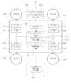
- the information processing system in this embodiment has a management server 1, one or more user terminals 2, one or more moving bodies 4 (e.g., flying bodies, running bodies, etc.), and one or more moving body storage devices 5.
- the management server 1, the user terminals 2, the moving bodies 4, and the moving body storage devices 5 are communicatively connected to each other via a network.
- the illustrated configuration is an example, and is not limited thereto.
- the configuration may be one in which the moving body storage device 5 is not included and the moving body is carried by the user.
- ⁇ Management Server 1> 2 is a diagram showing a hardware configuration of the management server 1. Note that the illustrated configuration is an example, and the management server 1 may have other configurations.
- the management server 1 is connected to a user terminal 2, a mobile object 4, and a mobile object storage device 5, and constitutes part of the system.
- the management server 1 may be a general-purpose computer such as a workstation or a personal computer, or may be logically realized by cloud computing.
- the management server 1 includes at least a processor 10, a memory 11, a storage 12, a transmission/reception unit 13, an input/output unit 14, etc., which are electrically connected to each other via a bus 15.
- the processor 10 is a computing device that controls the operation of the entire management server 1, controls the transmission and reception of data between each element, and performs information processing necessary for application execution and authentication processing.
- the processor 10 is a CPU (Central Processing Unit) and/or a GPU (Graphics Processing Unit), and executes programs for this system stored in the storage 12 and deployed in the memory 11 to perform various information processing operations.
- CPU Central Processing Unit
- GPU Graphics Processing Unit
- Memory 11 includes a main memory consisting of a volatile storage device such as DRAM (Dynamic Random Access Memory) and an auxiliary memory consisting of a non-volatile storage device such as a flash memory or HDD (Hard Disc Drive). Memory 11 is used as a work area for processor 10, and also stores the BIOS (Basic Input/Output System) that is executed when management server 1 is started, various setting information, etc.
- BIOS Basic Input/Output System
- Storage 12 stores various programs such as application programs.
- a database that stores data used for each process may be constructed in storage 12.
- the transmission/reception unit 13 connects the management server 1 to the network.
- the transmission/reception unit 13 may be equipped with a short-range communication interface for Bluetooth (registered trademark) and BLE (Bluetooth Low Energy).
- the input/output unit 14 includes information input devices such as a keyboard and mouse, and output devices such as a display.
- the bus 15 is commonly connected to each of the above elements and transmits, for example, address signals, data signals, and various control signals.
- ⁇ User Terminal 2> 3 also includes a processor 20, a memory 21, a storage 22, a transmission/reception unit 23, an input/output unit 24, etc., which are electrically connected to each other via a bus 25.
- the functions of each element can be configured in the same way as the management server 1 described above, so detailed explanations of each element will be omitted.
- the moving body 4 is a known moving body including an air vehicle such as a drone or an unmanned aerial vehicle, a running body such as an unmanned ground vehicle, etc., and is particularly a moving body that can be autonomously controlled. As a specific example of such a moving body, the moving body 4 will be described below.
- FIG. 4 is a block diagram showing a hardware configuration of the moving body 4.
- the flight controller 41 can have one or more processors such as a programmable processor (e.g., a central processing unit (CPU)).
- a programmable processor e.g., a central processing unit (CPU)
- Flight controller 41 also has and can access memory 411.
- Memory 411 stores logic, code, and/or program instructions that the flight controller can execute to perform one or more steps.
- Flight controller 41 may also include sensors 412, such as inertial sensors (accelerometers, gyro sensors), GPS sensors, proximity sensors (e.g., lidar), etc.
- the memory 411 may include, for example, a separable medium such as an SD card or random access memory (RAM) or an external storage device. Data acquired from the camera/sensors 42 may be directly transmitted to and stored in the memory 411. For example, still image/video data captured by a camera or the like may be recorded in an internal memory or an external memory, but is not limited to this, and may be recorded in at least one of the management server 1, the user terminal 2, or the mobile body storage device 5 from the camera/sensors 42 or the internal memory via the network NW.
- the camera 42 is installed on the mobile body 4 via a gimbal 43.
- the flight controller 41 includes a control module (not shown) configured to control the state of the moving object.
- the control module controls the propulsion mechanism (motor 45, etc.) of the moving object via an ESC 44 (Electric Speed Controller) in order to adjust the spatial arrangement, speed, and/or acceleration of the moving object having six degrees of freedom (translational motion x, y, and z , and rotational motion ⁇ x , ⁇ y , and ⁇ z ).
- the propeller 46 rotates by the motor 45 powered by a battery 48, thereby generating lift for the moving object.
- the control module can control one or more of the states of the mounted parts and sensors.
- the flight controller 41 can communicate with a transceiver 47 configured to transmit and/or receive data from one or more external devices (e.g., a transceiver 49, a terminal, a display device, or other remote control).
- a transceiver 49 can use any suitable communication means, such as wired or wireless communication.
- the transceiver unit 47 can utilize one or more of a local area network (LAN), a wide area network (WAN), infrared, wireless, WiFi, a point-to-point (P2P) network, a telecommunications network, cloud communications, etc.
- LAN local area network
- WAN wide area network
- P2P point-to-point
- the transmitter/receiver 47 can transmit and/or receive one or more of the following: data acquired by the sensors 42, processing results generated by the flight controller 41, specific control data, user commands from a terminal or a remote controller, etc.
- the sensors 42 may include an inertial sensor (acceleration sensor, gyro sensor), a GPS sensor, a proximity sensor (e.g., LiDAR (Light Detection And Ranging), etc.), or a vision/image sensor (e.g., a camera).
- the sensors 42 may also be referred to as "camera 42".
- the sensors 42 are configured to acquire, when an image is captured by the camera 42 as a vision/image sensor, information on the actual capturing position of the camera 42 in real space at the time the image was captured, the actual capturing direction which is the direction in real space to which the optical center axis of the camera 42 faces, the focal length and angle of view of the camera 42, and other capturing condition information in association with the image. Therefore, the image data of an image captured by the camera 42 according to this embodiment includes not only the image data, but also the above-mentioned capturing condition information linked thereto.
- ⁇ Management server functions> 5 is a block diagram illustrating functions implemented in the management server 1.
- the management server 1 has various functional units for executing a process of arranging a captured image in a corresponding three-dimensional model based on an image captured by a camera included in the sensors 42 of the mobile object 4 and image capture condition information associated therewith, and three-dimensional model data indicating the arrangement of components (e.g., walls, columns, stairs, equipment, etc.) within a structure (e.g., a building such as a building).
- the management server 1 includes a processor 10, a transmission/reception unit 13, and a storage unit 200.
- the processor 10 includes an actual shooting position information acquisition unit 110, a virtual distance generation unit 120, a size identification unit 130, an image projection unit 140, a difference detection unit 150, a shooting target identification unit 160, an image linking unit 170, and a movement execution unit 180.
- the storage unit 200 includes various databases, such as a three-dimensional data storage unit 210, a shooting image data storage unit 220, and a movement information storage unit 230.
- the three-dimensional data storage unit 210 stores three-dimensional model data showing the components inside and outside the structure and their positions.
- the three-dimensional model data may be any data as long as it is three-dimensional model data (more preferably three-dimensional model data having dimensional information) showing the arrangement of the components inside the structure, which is created based on data created with CAD (Computer-Aided Design) design software.
- CAD Computer-Aided Design
- it may be three-dimensional model data reconstructed from BIM (Building Information Modeling) data, CIM (Construction Information Modeling) data, CAD data, BIM data, etc., or it may be three-dimensional model data obtained by generating a component having a predetermined height based on two-dimensional design drawing data.
- the generation of the three-dimensional model data such as reconstruction may be executed by the processor 10 of the management server 1, or the management server 1 may acquire the three-dimensional model data generated by executing the process on an external device different from the management server 1.
- the three-dimensional model data showing the structure may be linked with information showing the type, size, scale, etc. of the structure.
- information on the three-dimensional model data for example, information showing a predetermined spatial area based on the three-dimensional model data (for example, a spatial area based on a structure such as the spatial area between pillar A and pillar B, or a spatial area defined by a three-dimensional coordinate system in which the three-dimensional model data is placed (particularly, a spatial area based on coordinates specified by a user operation)) may be stored in the three-dimensional data storage unit 210.
- the processor 10 of the management server 1 generates a virtual space represented by the three-dimensional model data in a three-dimensional coordinate system based on the three-dimensional model data stored in the three-dimensional data storage unit 210.
- the placement information of each three-dimensional model in the virtual space thus generated such as its placement position and orientation, is already known.
- the photographed image data storage unit 220 stores photographed image data captured by the sensors 42 of the moving object 4 and transmitted from the moving object 4 to the management server 1.
- the image data captured and acquired by the sensors 42 of the moving object 4 includes not only the image data, but also photographing condition information related to the actual photographing position in real space of the camera 42 at the time the image was captured, the actual photographing direction which is the direction in real space in which the optical center axis of the camera 42 faces, and the focal length of the camera 42, which are associated (linked) with the image. Therefore, the photographed image data stored in the photographed image data storage unit 220 includes image data and photographing condition information linked thereto.
- the photographing condition information may be metadata associated with the image data.
- the photographed image data stored in the photographed image data storage unit 220 may further include information on at least one of the photographed subject model present at the photographed subject position in the virtual space, identified by the photographed subject identification unit 160 of the processor 10 described below and linked to the image linking unit 170, or the photographed subject space. Details of the above-mentioned identification process and linking process by the photographed subject identification unit 160 and the image linking unit 170 will be described later. Furthermore, the photographed image data stored in the photographed image data storage unit 220 may be associated with information on the size of the image data at the photographed subject position, which is the position of the photographed subject in the virtual space, identified by the size identification unit 130 as described below.
- the movement information storage unit 230 stores movement information used for movement for the purpose of taking actual images of various objects inside and outside buildings, for example.
- the movement information includes, for example, movement route information (including waypoint information), movement speed, flight altitude, imaging conditions (imaging direction, imaging angle of view, imaging focal length, overlap rate of captured images, etc.), information acquired during movement (for example, image data and imaging condition information associated therewith, etc.), etc.
- the movement information can be generated, for example, by setting the parameters of various information included in the movement information on the management server 1 or the user terminal 2.
- the movement route may be generated by, for example, setting the position of the mobile body storage device 5 as the movement start position and the movement end position, and passing through each waypoint. Conversely, it may be configured such that, without the mobile body storage device 5, the position where the user carries the mobile body 4 is set as the movement start position (so-called home point), and the user retrieves the mobile body 4 at the movement end position (which may be back to the home point).
- it may be configured to generate a movement route including the position of the mobile body storage device 5 selected as the movement start position or movement end position based on the information of the mobile body storage device 5 managed by the management server 1 (for example, position information, storage state information, storage machine information, etc.).
- the actual shooting position information acquisition unit 110 acquires, as shooting condition information linked to the captured image data captured by the camera 42 of the moving body 4 and transmitted from the moving body 4 to the management server 1, in particular, actual shooting position information indicating the actual shooting position of the camera 42 in real space at the time the image was captured.
- the actual shooting position information acquisition unit 110 may further acquire information regarding the actual shooting direction, which is the direction in real space in which the optical center axis of the camera 42 faces, and the focal length and angle of view of the camera 42, from the above-mentioned shooting condition information linked to the acquired image data.
- the actual photographing position of the camera (sensors) 42 in real space is a position expressed in a three-dimensional coordinate system of real space. If the camera 42 of the moving body 4 includes a GNSS sensor (GPS sensor, etc.) and latitude and longitude information can be acquired by the GNSS sensor as position information of the sensors 42, the actual photographing position of the camera (sensors) 42 in real space may be expressed in latitude and longitude.
- GNSS sensor GPS sensor, etc.
- the actual photographing position of the camera (sensors) 42 in real space may be expressed as a position in a three-dimensional coordinate system with the origin being a reference position in real space (for example, the flight start position (home point) of the moving body 4).
- the processor 10 of the management server 1 When the processor 10 of the management server 1 generates a virtual space represented by the three-dimensional model data in a three-dimensional coordinate system based on the three-dimensional model data stored in the three-dimensional data storage unit 210, the processor 10 performs a process of constructing a correlation between the three-dimensional coordinate system of the real space and the three-dimensional coordinate system of the virtual space, for example by associating the three-dimensional coordinate system of the real space with the three-dimensional coordinate system of the virtual space.
- the processor 10 aligns and associates a reference position in the three-dimensional coordinate system of the real space (for example, the flight start position of the moving body 4) with a reference position in the three-dimensional coordinate system of the virtual space corresponding to that position, thereby constructing a correlation between the three-dimensional coordinate system of the real space and the three-dimensional coordinate system of the virtual space.
- This allows the processor 10 to convert and express the position in the three-dimensional coordinate system of the real space of the moving body 4 flying in the real space into the position in the three-dimensional coordinate system of the virtual moving body (a virtual object corresponding to the moving body 4 in the real space) in the virtual space. If the scale of the three-dimensional model data in the virtual space differs from the scale of the corresponding structure (composition) in the real space, the scale of the three-dimensional model data may be adjusted during alignment.
- the virtual distance generation unit 120 performs processing to generate virtual distance information indicating the virtual distance from a virtual shooting position corresponding to the real shooting position of the camera 42 in the real space to a shooting target position, which is the position of the shooting target in the virtual space, in the virtual space generated by the processor 10.
- the shooting target position in the virtual space may be, for example, coordinate information in the virtual space, the position of a three-dimensional model of the shooting target in the virtual space (virtual components such as walls, pillars, stairs, and equipment in a building in the virtual space), or any spatial region position in the virtual space.
- the virtual distance generation unit 120 performs a process of calculating a virtual distance, which is the distance from the virtual shooting position to the shooting target position, based on a virtual shooting position in the virtual space in the three-dimensional coordinate system of the virtual space and the shooting target position (the position of the three-dimensional model corresponding to the component of the shooting target), and generating virtual distance information.
- the virtual distance which is the distance from the virtual shooting position to the shooting target position
- the virtual distance can be obtained by determining the length of a line segment connecting the virtual shooting position and the shooting target position in the three-dimensional coordinate system of the virtual space along the shooting direction (particularly the optical axis direction).
- the size determination unit 130 performs processing to determine the size of the image data at the position of the subject to be photographed, which is the position of the subject to be photographed in the virtual space, based on the angle of view information and focal length information of the camera 42, which is the photographing condition information included in the photographed image data acquired when the camera 42 photographs an image, and the virtual distance information generated by the virtual distance generation unit 120.
- the size determination unit 130 determines the size of the image data at the position of the subject to be photographed.
- the size determination unit 130 uses the angle of view information and focal length information of the camera 42 linked to the captured image data to calculate the size of a first plane (the "near plane" of the viewing frustum shown in FIG. 6) that is a focal length n away from the virtual capture position C in the virtual space that corresponds to the actual capture position of the camera 42.
- the size of the first plane corresponds to the size of the captured image data of the subject captured by the camera 42.
- the size determination unit 130 uses the size of the first plane calculated as described above, the focal length information, and the virtual distance information generated by the virtual distance generation unit 120 to calculate the size of the image data in a second plane (the "far plane" of the viewing frustum shown in FIG. 6) that is a virtual distance f away from the virtual shooting position C.
- the size of the second plane is the size of the first plane enlarged according to the ratio of the focal length n and the virtual distance f, and is the size of the image data at the shooting target position.
- the size determination unit 130 calculates the size of the image data at the shooting target position as described above, making it possible to obtain the actual size of the component in real space corresponding to the three-dimensional model at the shooting target position from the size of that image data.
- the image projection unit 140 performs a process of projecting image data of the size specified by the size specification unit 130 onto the subject model, which is a three-dimensional model of the subject that exists at the subject position in the virtual space.
- the subject model which is a three-dimensional model of the subject that exists at the subject position in the virtual space.
- the difference detection unit 150 performs processing to detect the difference in shape between the subject shown in the image data projected by the image projection unit 140 into the virtual space and the subject model corresponding to that subject.
- the difference detection unit 150 extracts characteristic parts of the object to be photographed that appear in the projected image data (e.g., the outline of the cupboard that is the object to be photographed and the corners where the outlines intersect) and characteristic parts of the object to be photographed that appear in the object to be photographed onto which the image data is projected that correspond to the characteristic parts of the object to be photographed (e.g., the ridges of the object to be photographed that is a three-dimensional model of the cupboard and the corners where the ridges intersect), and detects the difference in shape or position between the object to be photographed that appears in the projected image data and the object to be photographed model based on the positional relationship between these characteristic parts.
- characteristic parts of the object to be photographed that appear in the projected image data e.g., the outline of the cupboard that is the object to be photographed and the corners where the outlines intersect
- characteristic parts of the object to be photographed that appear in the object to be photographed onto which the image data is projected that correspond to the characteristic parts of the object to be photographed (e.g., the ridges of
- the difference information obtained as a result of the detection process by the difference detection unit 150 can be used, for example, to correct the position, shape, size, etc. of the image data that the image projection unit 140 projects in the virtual space, and to position the image data so that it is appropriately superimposed on the object to be photographed model.
- the subject identification unit 160 performs processing to identify at least either the subject model present at the subject position in the virtual space or the subject space based on the center position of the angle of view of the camera 42 when the camera 42 captured the captured image data.
- the shooting target identification unit 160 first obtains a virtual shooting direction in the virtual space corresponding to the actual shooting direction of the camera 42 based on information on the actual shooting direction, which is the direction in real space to which the optical center axis of the camera 42 faces at the time the shooting image data was captured, among the shooting condition information acquired when the camera 42 captured the shooting image data and linked to the shooting image data.
- the virtual shooting direction in the virtual space can be expressed as a virtual straight line extending from a virtual shooting position in the virtual space corresponding to the actual shooting position of the camera 42 to the virtual shooting direction corresponding to the actual shooting direction of the camera 42.
- the center position of the angle of view of the camera 42 can correspond to the virtual shooting position in the virtual space.
- the shooting target identification unit 160 then identifies a shooting target model or shooting target space that exists at a shooting target position in the virtual space, where a virtual straight line extending in the virtual shooting direction from a virtual shooting position in the virtual space corresponding to the actual shooting position of the camera 42 intersects.
- the photographing subject identification unit 160 identifies at least one of the photographing subject model or the photographing subject space that exists at the photographing subject position in the virtual space, based on the center position of the angle of view of the camera 42 when the camera 42 captured the photographed image data.
- the image linking unit 170 links the image data to at least one of the subject model or the subject space identified by the subject identification unit 160 and stores the image data in the storage unit 200. More specifically, based on the identification information acquired as a result of the identification process by the subject identification unit 160, the image linking unit 170 associates the photographed image data captured by the camera 42 with the subject model or the subject space in the virtual space that corresponds to the subject in real space reflected in the photographed image data, and stores the photographed image data linked to the corresponding subject model or subject space in the virtual space in the photographed image data storage unit 220 of the storage unit 200.
- the movement execution unit 180 executes the movement of the moving body 4 for the purpose of taking real images of various shooting subjects inside and outside the building, etc., based on various movement information stored in the movement information storage unit 230.
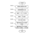
- Fig. 7 is a flowchart illustrating the information processing method according to this embodiment.
- the actual shooting position information acquisition unit 110 in the information processing system of this embodiment acquires shooting condition information linked to the captured image data from the captured image data captured by the camera 42 of the mobile body 4 and transmitted from the mobile body 4 to the management server 1 (step S101).
- the shooting condition information is acquired when the camera (sensors) 42 serving as a vision/image sensor captures an image, and includes information about the actual shooting position of the camera 42 in real space at the time the image was captured, the actual shooting direction which is the direction in real space to which the optical center axis of the camera 42 faces, the focal length and angle of view of the camera 42, etc., and is associated with the captured image data which is the data of the captured image.
- the actual shooting position information acquisition unit 110 particularly acquires information about the actual shooting position of the camera 42 in real space at the time the image was captured from the captured image data.
- the virtual distance generation unit 120 in the information processing system generates virtual distance information indicating the virtual distance from the virtual shooting position corresponding to the real shooting position of the camera 42 in the real space to the shooting target position, which is the position of the shooting target in the virtual space, in the virtual space generated by the processor 10 (step S102).
- the virtual distance generation unit 120 can obtain the virtual distance to the shooting target position, which is the position of the shooting target in the virtual space, by calculating the length of the line segment connecting the virtual shooting position in the virtual space and the shooting target position (the position of the three-dimensional model corresponding to the component of the shooting target) in the three-dimensional coordinate system of the virtual space.
- the size determination unit 130 in the information processing system determines the size of the image data at the position of the subject to be photographed in the virtual space based on the angle of view information and focal length information of the camera 42, which are included in the photographing condition information contained in the photographed image data acquired when the camera 42 photographed the image, and the virtual distance information generated by the virtual distance generation unit 120 (step S103).
- the size determination unit 130 calculates the size of a first plane (the "near plane" of the viewing frustum shown in FIG. 6) that is a focal distance away from the virtual shooting position in the virtual space corresponding to the actual shooting position of the camera 42, and then uses the size of the first plane, the focal distance, and the virtual distance to calculate the size of a second plane that is a virtual distance away from the virtual shooting position, thereby determining the size of the image data at the shooting target position in the virtual space.
- a first plane the "near plane" of the viewing frustum shown in FIG. 6
- the image data by determining the size of the image data at the position of the subject in the virtual space, when the captured image data is projected at the position of the subject in later processing (the position of the three-dimensional model corresponding to the component of the subject), it is possible to make the image data a size appropriate for the position of the subject. Furthermore, if the three-dimensional model data includes dimensional information and scale information, it is possible to obtain the actual size of the component in real space corresponding to the three-dimensional model at the position of the subject from the size of the image data.
- the image projection unit 140 in the information processing system projects image data of the size specified by the size specification unit 130 onto the subject model, which is a three-dimensional model of the subject that exists at the subject position in the virtual space (step S104).
- the subject model which is a three-dimensional model of the subject that exists at the subject position in the virtual space.
- the difference detection unit 150 in the information processing system detects the difference in shape between the subject shown in the image data projected by the image projection unit 140 into the virtual space and the subject model corresponding to that subject (step S105).
- the difference detection unit 150 extracts characteristic parts of the object to be photographed that are reflected in the projected image data and corresponding characteristic parts of the object to be photographed that are projected onto the image data, and detects the difference in shape or position between the object to be photographed that are reflected in the projected image data and the object to be photographed model based on the positional relationship between these characteristic parts.
- the difference information thus obtained for example, it becomes possible to correct the position, shape, size, etc. of the image data that the image projection unit 140 projects in the virtual space, and to arrange the image data so that it is appropriately superimposed on the object to be photographed model.
- the imaging subject identification unit 160 in the information processing system identifies at least one of the imaging subject model present at the imaging subject position in the virtual space or the imaging subject space based on the center position of the angle of view of the camera 42 when the camera 42 captured the captured image data (step S106).
- the shooting subject identification unit 160 first determines a virtual shooting direction in the virtual space corresponding to the actual shooting direction of the camera 42 based on information about the actual shooting direction, which is the direction in real space in which the optical center axis of the camera 42 faces at the time the captured image data was captured, and then identifies the shooting subject model or shooting subject space that exists at the shooting subject position in the virtual space, where a virtual straight line extending from the virtual shooting position in the virtual space corresponding to the actual shooting position of the camera 42 in the virtual space intersects with the virtual shooting direction.
- the image linking unit 170 in the information processing system links the image data to at least one of the subject model or subject space identified by the subject identification unit 160 and stores the image data in the storage unit 200 (step S107).
- This makes it possible, for example, to search for the subject model or subject space corresponding to the image data stored in the photographed image data storage unit 220, or to search for image data corresponding to the subject model or subject space stored in the three-dimensional data storage unit 210, and enables the image projection unit 140 to automatically identify the image data to be projected at the subject position in step S104.
- an information processing system or the like that can easily manage images captured by a moving body 4 in association with the position and size of the subject to be captured.
- the information processing method according to this embodiment includes identifying the size of image data at the position of the subject to be captured in virtual space, so that when the captured image data is projected onto the position of the subject to be captured (the position of the three-dimensional model corresponding to the constituent feature of the subject to be captured), the image data can be sized to suit the position of the subject to be captured, and further, if the three-dimensional model data includes dimensional information and scale information, it is possible to obtain the actual size of the constituent feature in real space corresponding to the three-dimensional model at the position of the subject to be captured from the size of the image data.
- the mobile object 4 may further include devices, equipment, etc. that are used to inspect the interior and/or exterior walls of the structure for the presence or absence of specific events. More specifically, any device necessary to know the state of the structure being inspected may be employed, such as an imaging device (visible light camera, infrared camera, metal detector, ultrasonic measuring device, etc.), a keystroke device, etc., a detection device (metal detector), a sound collection device, an odor measuring device, a gas detector, an air pollution measuring device, a detection device (a device for detecting cosmic rays, radiation, electromagnetic waves, etc.), etc.
- an imaging device visible light camera, infrared camera, metal detector, ultrasonic measuring device, etc.
- a keystroke device etc.
- a detection device metal detector
- a sound collection device such as an odor measuring device, a gas detector, an air pollution measuring device, a detection device (a device for detecting cosmic rays, radiation, electromagnetic waves, etc.), etc.
- the information processing method according to this embodiment may be executed, for example, during security or surveillance within a structure, and may further include devices, equipment, etc. used for security or surveillance. More specifically, any device necessary for capturing images and detecting abnormalities or intruders in the structure to be guarded or monitored, such as an imaging device (visible light camera, infrared camera, night vision camera, metal detector, ultrasonic measuring device, etc.) or a sensor device (motion sensor, infrared sensor, etc.), may be employed.
- an imaging device visible light camera, infrared camera, night vision camera, metal detector, ultrasonic measuring device, etc.
- a sensor device motion sensor, infrared sensor, etc.
- the mobile object 4 can be suitably used as a mobile object for photography equipped with a camera or the like, and can also be used in various industries such as security, infrastructure monitoring, surveying, inspection of buildings and structures such as sports venues, factories, and warehouses, and disaster response.
Landscapes
- Engineering & Computer Science (AREA)
- Theoretical Computer Science (AREA)
- Multimedia (AREA)
- Signal Processing (AREA)
- Physics & Mathematics (AREA)
- General Physics & Mathematics (AREA)
- Computer Vision & Pattern Recognition (AREA)
- Computer Graphics (AREA)
- Computer Hardware Design (AREA)
- General Engineering & Computer Science (AREA)
- Software Systems (AREA)
- Processing Or Creating Images (AREA)
- Studio Devices (AREA)
- Image Analysis (AREA)
Abstract
Le problème abordé par la présente invention consiste à fournir un système de traitement d'informations ou similaire qui peut facilement gérer une image capturée par un corps en mouvement en association avec une position à capturer. Selon un mode de réalisation de la présente invention, la solution consiste en un système de traitement d'informations qui comprend : une unité d'acquisition d'informations de position de capture d'image réelle (110) qui acquiert des informations de position de capture d'image réelle indiquant une position de capture d'image réelle dans un espace réel en association avec des données d'image capturée acquises ; une unité de génération de distance virtuelle (120) qui génère des informations de distance virtuelle indiquant une distance virtuelle entre une position de capture d'image virtuelle correspondant à la position de capture d'image réelle et une position à capturer dans un espace virtuel ; et une unité d'identification de taille (130) qui identifie la taille des données d'image au niveau de la position à capturer sur la base des informations d'angle de vue et des informations de distance focale correspondant au moment auquel les données d'image capturée ont été capturées, et sur la base des informations de distance virtuelle.
Priority Applications (3)
| Application Number | Priority Date | Filing Date | Title |
|---|---|---|---|
| PCT/JP2023/021232 WO2024252585A1 (fr) | 2023-06-07 | 2023-06-07 | Système de traitement d'informations et procédé de traitement d'informations |
| JP2023571627A JP7441579B1 (ja) | 2023-06-07 | 2023-06-07 | 情報処理システム及び情報処理方法 |
| JP2024018628A JP2024177053A (ja) | 2023-06-07 | 2024-02-09 | 情報処理システム及び情報処理方法 |
Applications Claiming Priority (1)
| Application Number | Priority Date | Filing Date | Title |
|---|---|---|---|
| PCT/JP2023/021232 WO2024252585A1 (fr) | 2023-06-07 | 2023-06-07 | Système de traitement d'informations et procédé de traitement d'informations |
Publications (1)
| Publication Number | Publication Date |
|---|---|
| WO2024252585A1 true WO2024252585A1 (fr) | 2024-12-12 |
Family
ID=90038501
Family Applications (1)
| Application Number | Title | Priority Date | Filing Date |
|---|---|---|---|
| PCT/JP2023/021232 Ceased WO2024252585A1 (fr) | 2023-06-07 | 2023-06-07 | Système de traitement d'informations et procédé de traitement d'informations |
Country Status (2)
| Country | Link |
|---|---|
| JP (2) | JP7441579B1 (fr) |
| WO (1) | WO2024252585A1 (fr) |
Families Citing this family (1)
| Publication number | Priority date | Publication date | Assignee | Title |
|---|---|---|---|---|
| JP7696129B1 (ja) * | 2024-11-05 | 2025-06-20 | 株式会社センシンロボティクス | 情報処理システム、情報処理方法及びプログラム |
Citations (5)
| Publication number | Priority date | Publication date | Assignee | Title |
|---|---|---|---|---|
| JP2003006680A (ja) * | 2001-06-20 | 2003-01-10 | Zenrin Co Ltd | 3次元電子地図データの生成方法 |
| JP2005339127A (ja) * | 2004-05-26 | 2005-12-08 | Olympus Corp | 画像情報表示装置及び画像情報表示方法 |
| JP2021103410A (ja) * | 2019-12-25 | 2021-07-15 | セコム株式会社 | 移動体及び撮像システム |
| JP2022507502A (ja) * | 2018-11-15 | 2022-01-18 | イーディーエックス テクノロジーズ インコーポレイテッド | 拡張現実(ar)のインプリント方法とシステム |
| KR20220031975A (ko) * | 2020-09-06 | 2022-03-15 | 주식회사 태울코리아 | 3차원 공간에서의 cctv 영상 범위를 이용한 공간 분석 방법 |
-
2023
- 2023-06-07 JP JP2023571627A patent/JP7441579B1/ja active Active
- 2023-06-07 WO PCT/JP2023/021232 patent/WO2024252585A1/fr not_active Ceased
-
2024
- 2024-02-09 JP JP2024018628A patent/JP2024177053A/ja active Pending
Patent Citations (5)
| Publication number | Priority date | Publication date | Assignee | Title |
|---|---|---|---|---|
| JP2003006680A (ja) * | 2001-06-20 | 2003-01-10 | Zenrin Co Ltd | 3次元電子地図データの生成方法 |
| JP2005339127A (ja) * | 2004-05-26 | 2005-12-08 | Olympus Corp | 画像情報表示装置及び画像情報表示方法 |
| JP2022507502A (ja) * | 2018-11-15 | 2022-01-18 | イーディーエックス テクノロジーズ インコーポレイテッド | 拡張現実(ar)のインプリント方法とシステム |
| JP2021103410A (ja) * | 2019-12-25 | 2021-07-15 | セコム株式会社 | 移動体及び撮像システム |
| KR20220031975A (ko) * | 2020-09-06 | 2022-03-15 | 주식회사 태울코리아 | 3차원 공간에서의 cctv 영상 범위를 이용한 공간 분석 방법 |
Also Published As
| Publication number | Publication date |
|---|---|
| JP7441579B1 (ja) | 2024-03-01 |
| JPWO2024252585A1 (fr) | 2024-12-12 |
| JP2024177053A (ja) | 2024-12-19 |
Similar Documents
| Publication | Publication Date | Title |
|---|---|---|
| JP7004374B1 (ja) | 移動体の移動経路生成方法及びプログラム、管理サーバ、管理システム | |
| JP7118490B1 (ja) | 情報処理システム、情報処理方法、プログラム、移動体、管理サーバ | |
| JP2025016555A (ja) | 位置算出方法及び情報処理システム | |
| JP2023100642A (ja) | 検査システム | |
| JP2024008901A (ja) | 3次元データ生成システム、3次元データ生成方法、及びマーカーメジャー | |
| JP2025003621A (ja) | 飛行体の飛行経路表示方法及び情報処理装置 | |
| JP2026012840A (ja) | 移動体の移動経路生成方法及びプログラム、管理サーバ、管理システム | |
| JP2024177053A (ja) | 情報処理システム及び情報処理方法 | |
| JP2023157826A (ja) | 情報処理システム及び移動体、情報処理方法、プログラム | |
| JP6730763B1 (ja) | 飛行体の飛行経路作成方法及び管理サーバ | |
| JP6681102B2 (ja) | 検査システム | |
| JP2024169573A (ja) | クレーン用撮影システム及びプログラム | |
| JP2024113101A (ja) | 飛行体の飛行経路作成方法及び管理サーバ | |
| JP7228298B1 (ja) | 情報処理システム、情報処理方法、プログラム、移動体、管理サーバ | |
| WO2021124579A1 (fr) | Procédé de capture d'image de véhicule volant et dispositif de traitement d'informations | |
| JP7696129B1 (ja) | 情報処理システム、情報処理方法及びプログラム | |
| JP7698364B2 (ja) | 情報処理システム及び移動体、情報処理方法、プログラム | |
| JP7573826B1 (ja) | 情報処理システム、情報処理方法及びプログラム | |
| JP7818277B2 (ja) | 情報処理装置、方法およびプログラム | |
| JP7370045B2 (ja) | 寸法表示システムおよび寸法表示方法 | |
| Kreinberg et al. | Lidar-VIO Based Mapping of Elevator Shaft with UAV for Verification of Spatial Dimensions | |
| WO2021049508A1 (fr) | Système d'affichage de dimensions, et procédé d'affichage de dimensions | |
| WO2026069667A1 (fr) | Procédé de traitement d'informations, dispositif de traitement d'informations et programme | |
| WO2024202553A1 (fr) | Procédé de traitement d'informations, dispositif de traitement d'informations, programme informatique, et système de traitement d'informations | |
| JP2023083072A (ja) | 方法、システムおよびプログラム |
Legal Events
| Date | Code | Title | Description |
|---|---|---|---|
| WWE | Wipo information: entry into national phase |
Ref document number: 2023571627 Country of ref document: JP |
|
| 121 | Ep: the epo has been informed by wipo that ep was designated in this application |
Ref document number: 23940686 Country of ref document: EP Kind code of ref document: A1 |
|
| NENP | Non-entry into the national phase |
Ref country code: DE |