WO2024252630A1 - Dispositif de commande de moteur - Google Patents
Dispositif de commande de moteur Download PDFInfo
- Publication number
- WO2024252630A1 WO2024252630A1 PCT/JP2023/021405 JP2023021405W WO2024252630A1 WO 2024252630 A1 WO2024252630 A1 WO 2024252630A1 JP 2023021405 W JP2023021405 W JP 2023021405W WO 2024252630 A1 WO2024252630 A1 WO 2024252630A1
- Authority
- WO
- WIPO (PCT)
- Prior art keywords
- command value
- torque
- steering
- vehicle
- torque command
- Prior art date
- Legal status (The legal status is an assumption and is not a legal conclusion. Google has not performed a legal analysis and makes no representation as to the accuracy of the status listed.)
- Ceased
Links
Images







Classifications
-
- B—PERFORMING OPERATIONS; TRANSPORTING
- B62—LAND VEHICLES FOR TRAVELLING OTHERWISE THAN ON RAILS
- B62D—MOTOR VEHICLES; TRAILERS
- B62D5/00—Power-assisted or power-driven steering
- B62D5/04—Power-assisted or power-driven steering electrical, e.g. using an electric servo-motor connected to, or forming part of, the steering gear
-
- B—PERFORMING OPERATIONS; TRANSPORTING
- B62—LAND VEHICLES FOR TRAVELLING OTHERWISE THAN ON RAILS
- B62D—MOTOR VEHICLES; TRAILERS
- B62D6/00—Arrangements for automatically controlling steering depending on driving conditions sensed and responded to, e.g. control circuits
Definitions
- This disclosure relates to a control device for an electric motor for steering angle control.
- Patent Document 1 discloses a motor control device that includes an assist torque command value setting unit that generates an assist torque command value using a torsion bar torque, a manual steering command value generation unit that generates a manual steering command value using the torsion bar torque and the assist torque command value, an integrated angle command value calculation unit that adds the manual steering command value to the automatic steering command value to calculate an integrated angle command value, and a switching unit that switches between a first control that controls the electric motor based only on the assist torque command value and a second control that controls the electric motor based on the integrated angle command value based on a switching signal.
- the objective of this disclosure is to provide a motor control device that can use a novel method to prevent the steering wheel from automatically rotating when the vehicle is stopped or the steering member is not being gripped and is in a hands-free state during driving assistance mode.
- One embodiment of the present disclosure provides a motor control device for controlling the drive of an electric motor of a steering device, the motor control device including: a first torque command value generation unit that generates a first torque command value using a target torque corresponding to the distance between the vehicle and a specified object in a driving assistance mode; a determination unit that determines whether an assistance stop condition is satisfied, that is, the vehicle is in a stopped state or the steering member is in a hands-off state in which it is not gripped; and a control unit that, in the driving assistance mode, drives and controls the electric motor based on the first torque command value if the assistance stop condition is not satisfied, and that drives and controls the electric motor based on a second torque command value that does not include the first torque command value if the assistance stop condition is satisfied.
- the steering wheel when in driving assistance mode, if the vehicle is stopped or the steering member is not being gripped and is in a hands-free state, the steering wheel can be prevented from being automatically rotated using a new method.
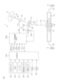
- FIG. 1 is a schematic diagram showing a schematic configuration of an electric power steering system to which a motor control device according to an embodiment of the present disclosure is applied.
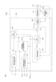
- FIG. 2 is a block diagram for explaining the electrical configuration of the motor control ECU.
- FIG. 3 is a graph showing an example of setting the assist torque command value T as relative to the torsion bar torque T tb .
- FIG. 4 is a schematic diagram showing an example of a reference EPS model.
- FIG. 5 is a block diagram showing the configuration of the manual steering command value calculation unit.
- FIG. 6 is a block diagram showing the configuration of the angle control unit.
- FIG. 7 is a schematic diagram showing an example of the configuration of a physical model of an electric power steering system.
- FIG. 8 is a block diagram showing the configuration of the disturbance torque estimating unit.
- FIG. 9 is a schematic diagram showing the configuration of the torque control unit.
- FIG. 10 is a flowchart showing the procedure of the target virtual spring reaction force setting process executed by the target virtual spring reaction force setting unit in the parking assist mode.
- FIG. 11 is a graph showing an example of setting the magnitude A of the target virtual spring reaction force T tb,d relative to the distance D obs to the noted obstacle.
- FIG. 12 is a schematic diagram for explaining that the sign of the target virtual spring reaction force T tb,d (target driving assist force T pas ) is determined depending on the traveling direction of the vehicle and the position of the target obstacle.
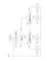
- FIG. 13 is a flowchart showing the procedure of the switch control process executed by the host ECU in the parking assistance mode.
- FIG. 10 is a flowchart showing the procedure of the target virtual spring reaction force setting process executed by the target virtual spring reaction force setting unit in the parking assist mode.
- FIG. 11 is a graph showing an example of setting the magnitude A of the target virtual spring reaction force T tb,d relative to
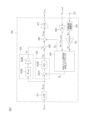
- FIG. 14 is a block diagram showing a modified example of the motor control ECU.
- FIG. 15 is a flowchart showing the procedure of a target driving assist force setting process executed by the target driving assist force setting unit in the parking assist mode.
- FIG. 16 is a flowchart showing the procedure of the second switch control process executed by the host ECU in the parking assistance mode.
- One embodiment of the present disclosure provides a motor control device for driving and controlling an electric motor of a steering device, the motor control device including: a first torque command value generation unit that generates a first torque command value using a target torque corresponding to a distance between a vehicle and a specified object in a driving assistance mode; a determination unit that determines whether an assistance stop condition is satisfied, that is, the vehicle is in a stopped state or the steering member is in a let-go state where it is not being gripped; and a control unit that, in the driving assistance mode, drives and controls the electric motor based on the first torque command value if the assistance stop condition is not satisfied, and drives and controls the electric motor based on a second torque command value that does not include the first torque command value if the assistance stop condition is satisfied.
- the steering wheel when in driving assistance mode, if the vehicle is stopped or the steering member is not being gripped and is in a hands-free state, the steering wheel can be prevented from being automatically rotated using a new method.
- the first torque command value generation unit includes a manual steering command value calculation unit that calculates a manual steering command value using a torsion bar torque, and an angle control unit that calculates the first torque command value based on the manual steering command value
- the manual steering command value calculation unit is configured to calculate the manual steering command value using an equation of motion of a reference model of the steering device
- the manual steering command value calculation unit is configured to calculate the manual steering command value using the target torque as a virtual spring reaction force in the equation of motion
- the second torque command value is an assist torque command value generated using a torsion bar torque.
- the first torque command value is the target torque
- the second torque command value is an assist torque command value that is generated using the torsion bar torque
- the determination unit determines that the vehicle is stopped when the shift position is the parking position.
- the determination unit determines that the vehicle is stopped when the vehicle speed is equal to or less than a predetermined first threshold.
- the determination unit determines that the torsion bar is in a let-go state when the torsion bar torque is equal to or less than a predetermined second threshold value.
- FIG. 1 is a schematic diagram showing the general configuration of an electric power steering system to which a motor control device according to one embodiment of the present disclosure is applied.
- the electric power steering system 1 includes a steering wheel (handle) 2 as a steering member for steering the vehicle, a steering mechanism 4 that steers the steered wheels 3 in conjunction with the rotation of the steering wheel 2, and a steering assist mechanism 5 that assists the driver in steering.
- the steering wheel 2 and the steering mechanism 4 are mechanically connected via a steering shaft 6 and an intermediate shaft 7.
- the steering wheel 2 is an example of a "steering member" in this disclosure.
- the steering shaft 6 includes an input shaft 8 connected to the steering wheel 2 and an output shaft 9 connected to the intermediate shaft 7.
- the input shaft 8 and the output shaft 9 are connected via a torsion bar 10 so as to be capable of relative rotation.
- a torque sensor 12 is disposed near the torsion bar 10.
- the torque sensor 12 detects a torsion bar torque (steering torque) Ttb applied to the steering wheel 2 based on the amount of relative rotational displacement between the input shaft 8 and the output shaft 9.
- the torsion bar torque Ttb detected by the torque sensor 12 is detected as a positive value for torque for steering to the right and a negative value for torque for steering to the left, for example, and the magnitude of the torsion bar torque Ttb increases as the absolute value increases .
- the steering mechanism 4 is made up of a rack-and-pinion mechanism including a pinion shaft 13 and a rack shaft 14 as a steering shaft.
- the steered wheels 3 are connected to each end of the rack shaft 14 via tie rods 15 and knuckle arms (not shown).
- the pinion shaft 13 is connected to the intermediate shaft 7.
- the pinion shaft 13 rotates in conjunction with the steering of the steering wheel 2.
- a pinion 16 is connected to the tip of the pinion shaft 13.
- the rack shaft 14 extends linearly in the left-right direction of the vehicle.
- a rack 17 that meshes with the pinion 16 is formed in the middle of the rack shaft 14 in the axial direction.
- the pinion 16 and rack 17 convert the rotation of the pinion shaft 13 into axial movement of the rack shaft 14.
- the steered wheels 3 can be steered by moving the rack shaft 14 in the axial direction.
- the steering assist mechanism 5 includes an electric motor 18 for generating a steering assist force (assist torque), and a reducer 19 for amplifying the output torque of the electric motor 18 and transmitting it to the steering mechanism 4.
- the reducer 19 is made up of a worm gear mechanism including a worm gear 20 and a worm wheel 21 that meshes with the worm gear 20.
- the reducer 19 is housed in a gear housing 22 that serves as a transmission mechanism housing.
- the reduction ratio (gear ratio) of the reducer 19 is represented as N.
- the reduction ratio N is defined as the ratio ( ⁇ wg / ⁇ WW ) of the worm gear angle ⁇ wg , which is the rotation angle of the worm gear 20, to the worm wheel angle ⁇ ww , which is the rotation angle of the worm wheel 21.
- the worm gear 20 is rotated by the electric motor 18.
- the worm wheel 21 is connected to the output shaft 9 so that they can rotate together.
- the worm gear 20 When the worm gear 20 is driven to rotate by the electric motor 18, the worm wheel 21 is driven to rotate, and motor torque is applied to the steering shaft 6, causing the steering shaft 6 (output shaft 9) to rotate. The rotation of the steering shaft 6 is then transmitted to the pinion shaft 13 via the intermediate shaft 7. The rotation of the pinion shaft 13 is converted into axial movement of the rack shaft 14. This causes the steered wheels 3 to be steered. In other words, by driving the worm gear 20 to rotate by the electric motor 18, steering assistance by the electric motor 18 and steering of the steered wheels 3 are possible.
- the electric motor 18 is provided with a rotation angle sensor 23 for detecting the rotation angle of the rotor of the electric motor 18.
- the torque applied to the output shaft 9 includes the motor torque by the electric motor 18 and a disturbance torque Tlc other than the motor torque.
- the disturbance torque Tlc other than the motor torque includes a torsion bar torque Ttb , a road reaction torque (road load torque) Trl , a friction torque Tf, etc.
- the torsion bar torque Ttb is a torque applied to the output shaft 9 from the steering wheel 2 side due to a force applied to the steering wheel 2 by the driver, a force generated by steering inertia, or the like.
- the road reaction torque Trl is a torque applied to the output shaft 9 from the steered wheels 3 via the rack shaft 14 due to the self-aligning torque generated in the tires, forces generated by the suspension and tire/wheel alignment, frictional forces of the rack and pinion mechanism, etc.
- the vehicle is equipped with a CCD (Charge Coupled Device) camera 25 that photographs the road ahead in the direction of travel of the vehicle, a GPS (Global Positioning System) 26 for detecting the vehicle's position, a radar 27 for detecting road shapes and obstacles, an ultrasonic sensor 28 for measuring the distance from the vehicle to obstacles, a vehicle speed sensor 29 for detecting the vehicle speed V, etc.
- CCD Charge Coupled Device
- GPS Global Positioning System
- the vehicle is further equipped with two mode switches 31, 32 for manually switching between driving modes.
- the driving modes include a manual driving mode in which steering is performed manually, and a driving assistance mode in which driving assistance control is performed.
- the CCD camera 25, GPS 26, radar 27, ultrasonic sensor 28, vehicle speed sensor 29, etc. are connected to a host ECU (Electronic Control Unit) 201 for driving assistance control. Based on the information obtained from the CCD camera 25, GPS 26, radar 27, ultrasonic sensor 28, vehicle speed sensor 29, etc., the host ECU 201 performs surrounding environment recognition, vehicle position estimation, route planning, etc., and determines control target values for steering and drive actuators.
- ECU Electronic Control Unit
- the driving assistance control is parking assistance control that assists in parking. Therefore, in this embodiment, the driving modes include a "manual driving mode” in which steering is performed by manual driving, and a “parking assistance mode” in which parking assistance control is performed.
- the host ECU 201 sets the driving mode based on the operation of the first mode switch 31 and the second mode switch 32. Specifically, when the first mode switch 31 is operated, the host ECU 201 sets the driving mode to the manual driving mode. When the second mode switch 32 is operated, the host ECU 201 sets the driving mode to the parking assistance mode.
- the host ECU 201 sets a switch control signal SW cont for controlling the first switch 55 (see FIG. 2) and the second switch 56 provided on the motor control ECU 202 side.
- the switch control signal SW cont takes a value of 0 or 1.
- the host ECU 201 sets the switch control signal SW cont by performing a switch control process described later.
- the host ECU 201 is an example of a "determination unit" in this disclosure.
- the obstacle that is predicted to be most likely to cause a collision with the vehicle in parking assistance mode will be referred to as the "obstacle of interest.”
- the host ECU 201 When the driving mode is the parking assistance mode, the host ECU 201 outputs a distance (absolute value) D obs from the vehicle to the noted obstacle, a traveling direction signal S dir indicating whether the vehicle is moving forward or backward, and an obstacle position signal P obs indicating whether the noted obstacle is on the right or left side of a straight line that includes the vehicle width center line as a part when viewed from the rear of the vehicle.
- the heading signal S dir in this embodiment takes the value 0 or 1.
- the obstacle position signal P obs takes a value of 0 or 1.
- the switch control signal SW cont the distance D obs from the vehicle to the target obstacle, the traveling direction signal S dir , the obstacle position signal P obs and the vehicle speed V are provided to the motor control ECU 202 via the in-vehicle network.
- the torsion bar torque T tb detected by the torque sensor 12 and the output signal of the rotation angle sensor 23 are input to the motor control ECU 202.
- the motor control ECU 202 controls the electric motor 18 based on these input signals and information provided from the higher-level ECU 201.
- the torsion bar torque T tb is also provided from the motor control ECU 202 to the higher-level control ECU 201 via the in-vehicle network.
- FIG. 2 is a block diagram illustrating the electrical configuration of the motor control ECU 202.
- the motor control ECU 202 includes a microcomputer 50, a drive circuit (inverter circuit) 41 controlled by the microcomputer 50 and supplying power to the electric motor 18, and a current detection circuit 42 for detecting the current flowing through the electric motor 18 (hereinafter referred to as "motor current I m ").
- the microcomputer 50 is equipped with a CPU and memory (ROM, RAM, non-volatile memory, etc.), and functions as multiple function processing units by executing a predetermined program.
- the multiple function processing units include an assist torque command value setting unit 51, a target virtual spring reaction force setting unit 52, a manual steering command value calculation unit 53, an angle control unit 54, a first switch 55, a second switch 56, an adder 57, and a torque control unit (current control unit) 58.
- the assist torque command value setting unit 51 sets an assist torque command value T as which is a target value of the assist torque required for manual operation.
- the assist torque command value T as may be referred to as an “assist torque command value T as for manual operation.”
- the assist torque command value setting unit 51 sets the assist torque command value T as based on the torsion bar torque T tb detected by the torque sensor 12.
- FIG. 3 is a graph showing an example of setting the assist torque command value T as relative to the torsion bar torque T tb .
- the assist torque command value T as is set to a positive value when a steering assist force for steering in the right direction is to be generated from the electric motor 18, and is set to a negative value when a steering assist force for steering in the left direction is to be generated from the electric motor 18.
- the assist torque command value T as is positive for a positive value of the torsion bar torque T tb , and is negative for a negative value of the torsion bar torque T tb .
- the assist torque command value T as is set so that its absolute value increases as the absolute value of the torsion bar torque T tb increases, and is set so that its absolute value decreases as the vehicle speed V increases.
- the assist torque command value setting unit 51 may calculate the assist torque command value T as by multiplying the torsion bar torque T tb by a preset constant.
- the target virtual spring reaction force setting unit 52 sets a target virtual spring reaction force T tb,d having a magnitude according to the distance Dobs from the vehicle to the noted obstacle, based on the distance Dobs from the vehicle to the noted obstacle, the traveling direction signal S dir, and the obstacle position signal Pobs provided by the upper ECU 201.
- the target virtual spring reaction force setting unit 52 sets the target virtual spring reaction force T tb,d by executing a target virtual spring reaction force setting process.
- the target virtual spring reaction force setting process will be described in detail later.
- the target virtual spring reaction force T tb,d is an example of a "target torque" in the present disclosure.
- the manual steering command value calculation unit 53 is provided to set a steering angle (more precisely, a rotation angle ⁇ c of the output shaft 9) corresponding to the steering wheel operation as a manual steering command value ⁇ md when the driver operates the steering wheel 2 in the parking assist mode.
- the manual steering command value calculation unit 53 generates the manual steering command value ⁇ md using the torsion bar torque T tb detected by the torque sensor 12 and the target virtual spring reaction force T tb,d set by the target virtual spring reaction force setting unit 52.
- the manual steering command value ⁇ md is represented by the amount of rotation (rotation angle) from the neutral position of the output shaft 9, the amount of rotation from the neutral position in the right steering direction is represented as a positive value, and the amount of rotation from the neutral position in the left steering direction is represented as a negative value. Details of the manual steering command value calculation unit 53 will be described later.
- the angle control unit 54 calculates a manual steering torque command value Tmd corresponding to the manual steering command value ⁇ md based on the manual steering command value ⁇ md .
- the manual steering torque command value Tmd is an example of a "first torque command value” in the present disclosure.
- the manual steering command value calculation unit 53 and the angle control unit 54 are an example of a "first torque command value generation unit” in the present disclosure. Details of the angle control unit 54 will be described later.
- the motor torque command value T m,cmd which is the output of the adding unit 57 , is given to a torque control unit 58 .
- the torque control unit 58 drives the drive circuit 41 so that the motor torque of the electric motor 18 approaches the motor torque command value Tm,cmd .
- the torque control unit 58 will be described in detail later.
- the first switch 55, the second switch 56, the adder 57, and the torque control unit 58 are an example of a "control unit" in this disclosure.
- the manual steering command value calculation unit 53 will now be explained in detail.
- the manual steering command value generating unit generates the manual steering command value ⁇ md by using the reference EPS model of Fig. 4.
- the reference EPS model of Fig. 4 is an example of the "reference model of the steering device" of the present disclosure.
- This reference EPS model is a single inertia model including a lower column.
- the lower column corresponds to the output shaft 9 and the worm wheel 21.
- this model is only an example, and an inertia model including a configuration other than the above (for example, a rack bar, etc.) may be used.
- Jmd is the inertia of the lower column (hereinafter referred to as "column inertia")
- ⁇ col is the rotation angle of the lower column
- Ttb is the torsion bar torque.
- the lower column is supplied with a torsion bar torque Ttb , a torque N ⁇ Tm acting on the output shaft 9 from the electric motor 18, and a road reaction torque (virtual reaction force) Trl .
- the road surface reaction torque T rl is expressed by the following equation (1) using the spring constant kmd of the virtual spring and the viscous damping coefficient cmd of the virtual damper.
- k md and the viscous damping coefficient c md are obtained in advance by experiment, analysis, etc.
- k md ⁇ col may be referred to as a virtual spring reaction force
- c md (d ⁇ col /dt) may be referred to as a virtual damper reaction force.
- J md ⁇ d 2 ⁇ col /dt 2 is the moment of inertia acting on the lower column.
- the manual steering command value generating unit substitutes the torsion bar torque Ttb detected by the torque sensor 12 into Ttb , substitutes the assist torque command value Tas set by the assist torque command value setting unit 51 into Tm , and calculates the rotation angle ⁇ col of the lower column by solving the differential equation of equation (2).Then, the manual steering command value generating unit generates the obtained rotation angle ⁇ col of the lower column as the manual steering command value ⁇ md.
- the method of setting the manual steering command value ⁇ md in this manner is referred to as a comparison method.
- the equation of motion of formula (2) is equivalent to an equation of motion in which T m is replaced with T as and ⁇ col is replaced with ⁇ md .
- the manual steering command value calculation unit 53 calculates the manual steering command value ⁇ md by utilizing the equation of motion (2) of the reference EPS model described above. Specifically, in this embodiment, the manual steering command value calculation unit 53 calculates the manual steering command value ⁇ md based on an equation of motion obtained by modifying the equation of motion (2) of the reference EPS model described above.
- FIG. 5 is a block diagram showing the configuration of the manual steering command value calculation unit 53.
- Jmd is the column inertia
- s is a differential operator
- ⁇ md is a manual steering command value, which corresponds to the rotation angle ⁇ col of the lower column in the comparison method
- cmd is a viscous damping coefficient of the virtual damper, which is obtained in advance by experiments, analyses, etc.
- the manual steering command value calculation unit 53 includes an addition/subtraction unit 101, an inertia division unit 102, a first integration unit 103, a second integration unit 104, and a virtual damper reaction force calculation unit 105.
- the addition/subtraction unit 101 receives as input the torsion bar torque T tb , the target virtual spring reaction force T tb,d , and the virtual damper reaction force c md ⁇ d ⁇ md /dt provided by a virtual damper reaction force calculation unit 105 .
- the inertia division unit 102 divides the moment of inertia Jmd ⁇ d2 ⁇ md / dt2 calculated by the addition/subtraction unit 101 by the column inertia Jmd to calculate a second-order differential value d2 ⁇ md / dt2 of the manual steering command value ⁇ md .
- the first integration unit 103 calculates a first-order differential value d ⁇ md /dt of the manual steering command value ⁇ md by integrating a second-order differential value d 2 ⁇ md /dt 2 of the manual steering command value ⁇ md .
- the second integral unit 104 calculates the manual steering command value ⁇ md by integrating the first-order differential value d ⁇ md /dt of the manual steering command value ⁇ md .
- This manual steering command value ⁇ md is output from the manual steering command value calculation unit 53.
- the virtual damper reaction force calculation unit 105 calculates a virtual damper reaction force c md ⁇ d ⁇ md /dt by multiplying the first-order differential value d ⁇ md /dt of the manual steering command value ⁇ md calculated by the first integration unit 103 by a viscous damping coefficient c md .
- This virtual damper reaction force c md ⁇ d ⁇ md / dt is fed back to the addition and subtraction unit 101.
- the manual steering command value calculation unit 53 calculates the manual steering command value ⁇ md based on the equation of motion shown in the following equation (3).
- J md ⁇ d 2 ⁇ md /dt 2 is the moment of inertia
- c md ⁇ d ⁇ md /dt is the virtual damper reaction force
- T tb,d is a target virtual spring reaction force having a magnitude according to the distance D obs from the vehicle to the obstacle of interest.
- the manual steering command value calculation unit 53 may calculate N ⁇ T as by multiplying the assist torque command value T as by the reduction ratio N, and provide the obtained N ⁇ T as to the addition/subtraction unit 101.
- the addition/subtraction unit 101 subtracts the virtual damper reaction force c md ⁇ d ⁇ md /dt and the target virtual spring reaction force T tb,d from a value obtained by adding N ⁇ T as to the torsion bar torque T tb .
- the manual steering command value calculation unit 53 calculates the manual steering command value ⁇ md based on the equation of motion in which N ⁇ T as is added to the right side of the above formula (3).
- FIG. 6 is a block diagram showing the configuration of the angle control unit 54.
- the angle control unit 54 calculates a manual steering torque command value Tmd based on the manual steering command value ⁇ md .
- the angle control unit 54 includes a low-pass filter (LPF) 61, a feedback control unit 62, a feedforward control unit 63, a disturbance torque estimation unit 64, a torque addition unit 65, a disturbance torque compensation unit 66, a first reduction gear ratio division unit 67, a reduction gear ratio multiplication unit 68, a rotation angle calculation unit 69, and a second reduction gear ratio division unit 70.
- LPF low-pass filter
- the reduction ratio multiplication unit 68 multiplies the motor torque command value Tm,cmd calculated by the addition unit 57 (see FIG. 2) by the reduction ratio N of the reducer 19, thereby converting the motor torque command value Tm,cmd into an output shaft torque command value N ⁇ Tm,cmd acting on the output shaft 9 (worm wheel 21).
- the rotation angle calculation unit 69 calculates a rotor rotation angle ⁇ m of the electric motor 18 based on the output signal of the rotation angle sensor 23.
- the second reduction ratio division unit 70 converts the rotor rotation angle ⁇ m into a rotation angle (actual steering angle) ⁇ c of the output shaft 9 by dividing the rotor rotation angle ⁇ m calculated by the rotation angle calculation unit 69 by the reduction ratio N.
- the steering angle ⁇ c is represented by the amount of rotation (rotation angle) from the neutral position of the output shaft 9, where the amount of rotation from the neutral position in the right steering direction is represented as a positive value, and the amount of rotation from the neutral position in the left steering direction is represented as a negative value.
- the low-pass filter 61 performs low-pass filtering on the manual steering command value ⁇ md .
- the manual steering command value ⁇ mdl after the low-pass filtering is provided to a feedback control unit 62 and a feedforward control unit 63.
- the low-pass filter 61 does not necessarily have to be provided.
- the feedback control unit 62 is provided to bring the steering angle estimated value ⁇ calculated by the disturbance torque estimation unit 64 closer to the manual steering command value ⁇ mdl after low-pass filter processing.
- the feedback control unit 62 includes an angle deviation calculation unit 62A and a PD control unit 62B.
- the angle deviation calculation unit 62A may calculate the deviation ( ⁇ mdl - ⁇ c ) between the manual steering command value ⁇ mdl and the steering angle ⁇ c calculated by the second reduction ratio division unit 70 as the angle deviation ⁇ .
- the PD control unit 62B performs a PD calculation (proportional differential calculation) on the angle deviation ⁇ calculated by the angle deviation calculation unit 62A to calculate a feedback control torque Tfb .
- the feedback control torque Tfb is provided to a torque addition unit 65.
- the feedforward control unit 63 is provided to improve the control response by compensating for a delay in response due to the inertia of the electric power steering system 1.
- the feedforward control unit 63 includes an angular acceleration calculation unit 63A and an inertia multiplication unit 63B.
- the angular acceleration calculation unit 63A calculates a target angular acceleration d 2 ⁇ mdl /dt 2 by second-order differentiation of the manual steering command value ⁇ mdl .
- the inertia J is obtained, for example, from a physical model (see FIG. 7) of the electric power steering system 1, which will be described later.
- the feedforward control torque Tff is provided to the torque addition unit 65 as an inertia compensation value.
- the torque addition unit 65 calculates a basic torque command value ( Tfb + Tff ) by adding the feedforward control torque Tff to the feedback control torque Tfb .
- the disturbance torque estimating unit 64 is provided to estimate a nonlinear torque (disturbance torque: torque other than motor torque) that occurs as a disturbance in the plant (the control target of the electric motor 18).
- the disturbance torque estimating unit 64 estimates the disturbance torque (disturbance load) T lc , the steering angle ⁇ , and the steering angle differential value (angular velocity) d ⁇ c /dt based on the output shaft torque command value N ⁇ T m,cmd and the steering angle ⁇ c .
- the estimated values of the disturbance torque T lc , the steering angle ⁇ c, and the steering angle differential value (angular velocity) d ⁇ c /dt are represented by ⁇ T lc , ⁇ c, and d ⁇ c /dt, respectively.
- the details of the disturbance torque estimating unit 64 will be described later.
- the disturbance torque estimated value ⁇ Tlc calculated by the disturbance torque estimating section 64 is provided as a disturbance torque compensation value to a disturbance torque compensating section 66.
- the steering angle estimated value ⁇ ⁇ c calculated by the disturbance torque estimating section 64 is provided to an angle deviation calculating section 62A.
- the manual steering torque command value Tmdo is provided to a first reduction ratio division unit 67.
- the first reduction ratio division unit 67 calculates a manual steering torque command value Tmd (torque command value for the electric motor 18) by dividing the manual steering torque command value Tmdo by the reduction ratio N.
- This manual steering torque command value Tmd is provided to the first switch 55 (see FIG. 2).
- the disturbance torque estimation unit 64 will be described in detail.
- the disturbance torque estimation unit 64 is composed of a disturbance observer that estimates the disturbance torque T lc , the steering angle ⁇ c and the angular velocity d ⁇ c /dt using, for example, a physical model 300 of the electric power steering system 1 shown in FIG.
- This physical model 300 includes a plant (an example of a motor-driven object) 301 including an output shaft 9 and a worm wheel 21 fixed to the output shaft 9.
- a torsion bar torque Ttb is applied to the plant 301 from the steering wheel 2 via the torsion bar 10, and a road reaction torque Trl is applied from the steered wheels 3 side.
- an output shaft torque command value N ⁇ T m,cmd is applied to the plant 301 via the worm gear 20 , and a friction torque T f is applied due to friction between the worm wheel 21 and the worm gear 20 .
- Tlc indicates a disturbance torque other than the motor torque applied to the plant 301.
- the disturbance torque Tlc is shown as the sum of the torsion bar torque Ttb , the road surface reaction torque Trl, and the friction torque Tf , but in reality, the disturbance torque Tlc includes torques other than these.
- x is a state variable vector
- u1 is a known input vector
- u2 is an unknown input vector
- y is an output vector (measured value).
- A is a system matrix
- B1 is a first input matrix
- B2 is a second input matrix
- C is an output matrix
- D is a direct feedthrough matrix.
- the state equation is expanded to a system including the unknown input vector u2 as one of the states.
- the state equation of the expanded system (expanded state equation) is expressed by the following equation (6).
- x e is a state variable vector of the extended system, and is expressed by the following formula (7).
- a e is the system matrix of the extended system
- B e is the known input matrix of the extended system
- C e is the output matrix of the extended system.
- ⁇ xe represents an estimated value of xe .
- L is the observer gain.
- ⁇ y represents an estimated value of y.
- ⁇ xe is expressed by the following equation (9).
- ⁇ c is an estimate of ⁇ c and ⁇ T lc is an estimate of T lc .
- the disturbance torque estimation unit 64 calculates the state variable vector ⁇ x e based on the above equation (8).
- FIG. 8 is a block diagram showing the configuration of the disturbance torque estimation unit 64.
- the disturbance torque estimation unit 64 includes an input vector input unit 81, an output matrix multiplication unit 82, a first adder unit 83, a gain multiplication unit 84, an input matrix multiplication unit 85, a system matrix multiplication unit 86, a second adder unit 87, an integrator unit 88, and a state variable vector output unit 89.
- the output shaft torque command value N ⁇ T m,cmd calculated by the reduction ratio multiplication section 68 (see FIG. 6) is given to an input vector input section 81.
- the input vector input section 81 outputs an input vector u1 .
- the output of the integrator 88 becomes the state variable vector ⁇ x e (see equation (9) above).
- an initial value is given as the state variable vector ⁇ x e .
- the initial value of the state variable vector ⁇ x e is, for example, 0.
- the system matrix multiplication unit 86 multiplies the state variable vector ⁇ xe by the system matrix A e .
- the output matrix multiplication unit 82 multiplies the state variable vector ⁇ xe by the output matrix C e .
- the gain multiplier 84 multiplies the output (y - ⁇ y) of the first adder 83 by the observer gain L (see equation (8) above).
- the input matrix multiplication unit 85 multiplies the input vector u 1 output from the input vector input unit 81 by the input matrix B e .
- the second adder 87 adds the output (B e ⁇ u 1 ) of the input matrix multiplication unit 85, the output (A e ⁇ ⁇ x e ) of the system matrix multiplication unit 86, and the output (L(y- ⁇ y)) of the gain multiplication unit 84 to calculate a differential value d ⁇ x e /dt of the state variable vector.
- the integrator 88 integrates the output (d ⁇ x e /dt) of the second adder 87 to calculate the state variable vector ⁇ x e .
- the state variable vector output unit 89 calculates a disturbance torque estimate value ⁇ T lc , a steering angle estimate value ⁇ c, and an angular velocity estimate value d ⁇ c /dt based on the state variable vector ⁇ x e .
- a typical disturbance observer consists of an inverse model of the plant and a low-pass filter.
- the equation of motion of the plant is expressed by equation (4) as described above. Therefore, the inverse model of the plant is expressed by the following equation (10).
- the inputs to a general disturbance observer are J ⁇ d2 ⁇ c / dt2 and N ⁇ Tm ,cmd , and since the second-order differential value of the steering angle ⁇ c is used, it is significantly affected by noise from the rotation angle sensor 23.
- the extended state observer of the above-mentioned embodiment estimates the disturbance torque in an integral manner, so that it is possible to reduce the influence of noise due to differentiation.
- a general disturbance observer consisting of an inverse model of the plant and a low-pass filter may be used as the disturbance torque estimation unit 64.
- FIG. 9 is a schematic diagram showing the configuration of the torque control unit 58.
- the torque control unit 58 (see FIG. 2) includes a motor current command value calculation unit 91, a current deviation calculation unit 92, a PI control unit 93, and a PWM (Pulse Width Modulation) control unit 94.
- the motor current command value calculation unit 91 calculates the motor current command value I m,cmd by dividing the motor torque command value T m,cmd calculated by the adder 57 (see FIG. 2) by the torque constant Kt of the electric motor 18 .
- the PI control unit 93 performs a PI calculation (proportional integral calculation) on the current deviation ⁇ I calculated by the current deviation calculation unit 92 to generate a drive command value for guiding the motor current I m flowing through the electric motor 18 to the motor current command value I m,cmd .
- the PWM control unit 94 generates a PWM control signal with a duty ratio corresponding to the drive command value, and supplies it to the drive circuit 41. As a result, power corresponding to the drive command value is supplied to the electric motor 18.
- FIG. 10 is a flowchart showing the steps of the target virtual spring reaction force setting process executed by the target virtual spring reaction force setting unit 52 in the parking assistance mode.
- the target virtual spring reaction force setting unit 52 sets a magnitude A (A ⁇ 0) of a target virtual spring reaction force T tb,d based on a distance D obs from the vehicle to a target obstacle provided by the host ECU 201 (step S1).
- FIG. 11 is a graph showing an example of setting the magnitude A of the target virtual spring reaction force T tb,d versus the distance D obs from the vehicle to the obstacle of interest.
- the magnitude A of the target virtual spring reaction force T tb,d is the maximum value A max .
- the magnitude A of the target virtual spring reaction force T tb,d is 0.
- the magnitude A of the target virtual spring reaction force T tb,d is set to decrease from the maximum value A max to 0 as the distance D obs increases.
- the magnitude A of the target virtual spring reaction force T tb,d is set to the maximum value A max only when the distance D obs is 0.
- the magnitude A of the target virtual spring reaction force T tb,d for a range of the distance D obs from 0 to a predetermined value greater than 0 may be set to the maximum value A max .
- the threshold value Dth is set to a value that is considered to be unnecessary to generate a driving support force for avoiding a collision with the noted obstacle if the distance Dobs from the vehicle to the noted obstacle is equal to or greater than the threshold value Dth .
- the threshold value Dth is set to a value that is considered to be unnecessary to generate a driving support force for avoiding a collision with the noted obstacle if the distance Dobs from the vehicle to the noted obstacle is less than the threshold value Dth .
- the target virtual spring reaction force setting unit 52 determines whether or not the traveling direction signal S dir is 0 (step S2). If the traveling direction signal S dir is 0 (step S2: YES), that is, if the traveling direction is forward, the target virtual spring reaction force setting unit 52 determines whether or not the obstacle position signal P obs is 0 (step S3).
- step S3 YES
- the target virtual spring reaction force setting unit 52 sets A set in step S1 as the target virtual spring reaction force T tb,d (step S4). That is, the target virtual spring reaction force setting unit 52 sets the target virtual spring reaction force T tb,d to a positive value. Then, the target virtual spring reaction force setting unit 52 returns to step S1.
- step S3 when it is determined that the obstacle position signal P obs is 1 (step S3: NO), that is, when the noted obstacle is present on the left side when viewed from the rear to the front of the vehicle (left side in the forward direction), the target virtual spring reaction force setting unit 52 sets the value -A obtained by adding a negative sign to the value A set in step S1 as the target virtual spring reaction force T tb,d (step S5). In other words, the target virtual spring reaction force setting unit 52 sets the value of the target virtual spring reaction force T tb,d to a negative value. Then, the target virtual spring reaction force setting unit 52 returns to step S1.
- step S2 when it is determined that the traveling direction signal S_dir is 1 (step S2: NO), that is, when the traveling direction is reverse, the target virtual spring reaction force setting unit 52 determines whether or not the obstacle position signal P_obs is 0 (step S6).
- step S6 When the obstacle position signal P obs is 0 (step S6: YES), that is, when the target obstacle is present on the right side (left side in the backward traveling direction) when viewed from the rear of the vehicle to the front, the target virtual spring reaction force setting unit 52 sets A set in step S1 as the target virtual spring reaction force T tb,d (step S7). That is, the target virtual spring reaction force setting unit 52 sets the target virtual spring reaction force T tb,d to a positive value. Then, the target virtual spring reaction force setting unit 52 returns to step S1.
- step S6 when it is determined that the obstacle position signal P obs is 1 (step S6: NO), that is, when the noted obstacle is present on the left side when viewed from the rear to the front of the vehicle (the right side in the backward traveling direction), the target virtual spring reaction force setting unit 52 sets the value -A obtained by adding a negative sign to the value A set in step S1 as the target virtual spring reaction force T tb,d (step S8). In other words, the target virtual spring reaction force setting unit 52 sets the value of the target virtual spring reaction force T tb,d to a negative value. Then, the target virtual spring reaction force setting unit 52 returns to step S1.
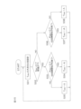
- FIG. 13 is a flowchart showing the steps of the switch control process executed by the host ECU 201 in parking assistance mode.
- the host ECU 201 sets the switch control signal SW_cont to 0 (step S11). This turns off the first switch 55 and turns on the second switch 56. This causes the electric motor 18 to be driven and controlled based on the assist torque command value T_as .
- the host ECU 201 obtains a distance D obs from the vehicle to the noted obstacle (step S12), and determines whether the obtained distance D obs is less than a predetermined threshold D th (D th >0) (step S13).
- step S13 determines whether the assist force stop condition is met, that is, the vehicle is stopped or the steering member is not gripped and is in a let-go state (step S14).
- the host ECU 201 determines that the support force stop condition is met when it is determined that the vehicle is stopped, when it is determined that the vehicle is in a hands-off state, or when it is determined that the vehicle is stopped and hands-off.
- the host ECU 201 determines that the support force stop condition is not met when it is determined that the vehicle is not stopped and hands-off.
- the determination of whether the vehicle is stopped may be made based on the shift position. Specifically, the vehicle may be determined to be stopped when the shift position is the parking position.
- the determination of whether the vehicle is stopped may be made based on the vehicle speed V. Specifically, the vehicle may be determined to be stopped when the vehicle speed V is equal to or lower than a predetermined speed.
- the determination of whether the vehicle is stopped may also be made based on the relative speed between the obstacle and the vehicle obtained by clearance sonar, radar, or image recognition. Specifically, the vehicle may be determined to be stopped when the relative speed between the obstacle and the vehicle is equal to or less than a predetermined relative speed. The determination of whether the vehicle is stopped may also be made by a known method other than these methods.
- the determination as to whether or not the hand is released is performed based on the torsion bar torque Tth . Specifically, when the torsion bar torque Tth is equal to or less than a predetermined value, the hand is released.
- the determination as to whether or not the hand is released may be performed by a known method other than this method.
- step S14 NO
- the host ECU 201 sets the switch control signal SW cont to 1 (step S15).
- the first switch 55 is turned on and the second switch 56 is turned off.
- the electric motor 18 is controlled to be driven based on the manual steering torque command value T md .
- a driving assist force (driving assist force for avoiding a collision with the noted obstacle) based on the target virtual spring reaction force Ttb,d set by the target virtual spring reaction force setting unit 52 is applied.
- This driving assist force causes the vehicle to be steered in a direction away from the noted obstacle.
- step S13 If it is determined in step S13 that the distance D obs is equal to or greater than a predetermined threshold value D th (step S13: NO) or if it is determined in step S14 that the assist force stop condition is satisfied (step S14: YES), the host ECU 201 sets the switch control signal SW cont to 0 (step S16). This turns off the first switch 55 and turns on the second switch 56. This causes the electric motor 18 to be driven and controlled based on the assist torque command value T as .
- the driving assistance force based on the target virtual spring reaction force T tb,d does not act.
- the driving assistance force based on the target virtual spring reaction force T tb,d does not act.
- the steering wheel 2 can be prevented from being automatically rotated.
- step S16 the host ECU 201 returns to step S12.
- the switch control signal SW cont is set to 0, so that the first switch 55 is turned off and the second switch 56 is turned on. As a result, the electric motor 18 is controlled to be driven based on the assist torque command value T as .
- FIG. 14 is a block diagram showing a modified example of the motor control ECU.
- the parts corresponding to those in FIG. 2 are denoted by the same reference numerals as in FIG. 2.
- the switch control signal SW cont the distance Dobs from the vehicle to the noted obstacle, the obstacle position signal Pobs , the traveling direction signal Sdir , and the vehicle speed V are transmitted from the host ECU 201 to the motor control ECU 202A.
- the host ECU 201 also performs a switch control process (hereinafter referred to as "second switch control process") for controlling the on/off of the switch 55A in Fig. 14.
- the second switch control process will be described in detail later.
- the microcomputer 50 in the motor control ECU 202A includes, as multiple functional processing units, an assist torque command value setting unit 51, a target driving assist force setting unit 52A, a switch 55A, an adder 57A, and a torque control unit (current control unit) 58.
- the assist torque command value setting unit 51 and the torque control unit 58 are similar to the assist torque command value setting unit 51 and the torque control unit 58 in FIG. 2, respectively, and therefore will not be described.
- the assist torque command value T as set by the assist torque command value setting section 51 is provided to an adding section 57A.
- the target driving support force setting unit 52A sets a target driving support force Tpas for parking support control based on a distance Dobs from the vehicle to the target obstacle, an obstacle position signal Pobs , and a traveling direction signal Sdir provided from the upper ECU 201 during the parking support mode.
- the target driving support force setting unit 52A executes a target driving support force setting process for setting the target driving support force Tpas .
- the target driving support force Tpas is an example of a "target torque” and a "first torque command value" in the present disclosure.
- the target driving support force setting unit 52A is an example of a "first torque command value generating unit" in the present disclosure. The target driving support force setting process will be described in detail later.
- the target driving assist force Tpas set by the target driving assist force setting unit 52A is applied to the switch 55A.
- the host ECU 201 sets the switch control signal SW cont to 0.
- the driving mode is the parking assistance mode
- the host ECU 201 sets the switch control signal SW cont by a second switch control process described later.
- the motor torque command value T m,cmd which is the output of the adding section 57A, is given to a torque control section 58 .
- Switch 55A, adder 57A, and torque control unit 58 are an example of a “control unit" in this disclosure.
- FIG. 15 is a flowchart showing the steps of the target driving assist force processing executed by the target driving assist force setting unit 52A in the parking assist mode.
- the target driving assist force setting unit 52A sets the magnitude A (A ⁇ 0) of the target driving assist force T pas based on the distance D obs from the vehicle to the noted obstacle provided by the host ECU 201 (step S31).
- An example of setting the magnitude A of the target driving assist force Tpas relative to the distance Dobs from the vehicle to the noted obstacle is similar to the example of setting the magnitude A of the target virtual spring reaction force Ttb,d described using FIG.
- the magnitude A of the target driving assist force T pas is the maximum value A max . If a predetermined value greater than 0 is set as a threshold D th , when the distance D obs is equal to or greater than the threshold D th , the magnitude A of the target driving assist force T pas is 0. When the distance D obs is in the range of 0 or more and equal to or less than the threshold D th , the magnitude A of the target driving assist force T pas is set to decrease from the maximum value A max to 0 as the distance D obs increases.
- the magnitude A of the target driving assistance force T pas is set to the maximum value A max only when the distance D obs is 0.
- the magnitude A of the target driving assistance force T pas for a range of the distance D obs from 0 to a predetermined value greater than 0 may be set to the maximum value A max .
- the target driving assist force setting unit 52A determines whether or not the traveling direction signal S dir is 0 (step S32). If the traveling direction signal S dir is 0 (step S32: YES), that is, if the traveling direction is forward, the target driving assist force setting unit 52A determines whether or not the obstacle position signal P obs is 0 (step S33).
- step S33 YES
- the target driving support force setting unit 52A sets the value ⁇ A obtained by adding a negative sign to A set in step S31 as the target driving support force T pas (step S34). That is, the target driving support force setting unit 52A sets the value of the target driving support force T pas to a negative value. Then, the target driving support force setting unit 52A returns to step S31.
- step S33 when it is determined that the obstacle position signal P obs is 1 (step S33: NO), that is, when the noted obstacle is present on the left side when viewed from the rear to the front of the vehicle (left side in the forward direction), the target driving support force setting unit 52A sets A set in step S31 as the target driving support force T pas (step S35). In other words, the target driving support force setting unit 52A sets the target driving support force T pas to a positive value. Then, the target driving support force setting unit 52A returns to step S31.
- step S32 when it is determined that the traveling direction signal S_dir is 1 (step S32: NO), that is, when the traveling direction is reverse, the target driving support force setting unit 52A determines whether or not the obstacle position signal P_obs is 0 (step S36).
- step S36 When the obstacle position signal P obs is 0 (step S36: YES), that is, when the noted obstacle is present on the right side (left side in the reverse direction) when viewed from the rear of the vehicle to the front, the target driving support force setting unit 52A sets the value ⁇ A obtained by adding a negative sign to A set in step S31 as the target driving support force T pas (step S37). That is, the target driving support force setting unit 52A sets the value of the target driving support force T pas to a negative value. Then, the target driving support force setting unit 52A returns to step S31.
- step S36 when it is determined that the obstacle position signal P obs is 1 (step S36: NO), that is, when the noted obstacle is present on the left side (right side in the reverse direction) when viewed from the rear of the vehicle to the front, the target driving support force setting unit 52A sets A set in step S31 as the target driving support force T pas (step S38). In other words, the target driving support force setting unit 52A sets the value of the target driving support force T pas to a positive value. Then, the target driving support force setting unit 52A returns to step S31.
- the target driving assist force setting unit 52A sets the target driving assist force Tpas to a negative value (see step S34).
- the target driving assist force setting unit 52A sets the target driving assist force Tpas to a positive value (see step S35).
- the target driving assist force setting unit 52A sets the target driving assist force Tpas to a negative value (see step S37).
- the target driving assist force setting unit 52A sets the target driving assist force Tpas to a positive value (see step S38).
- FIG. 16 is a flowchart showing the steps of the second switch control process executed by the host ECU 201 in the parking assistance mode.
- the host ECU 201 sets the switch control signal SW_cont to 0 (step S41), which turns off the switch 55A. This causes the electric motor 18 to be driven and controlled based on the assist torque command value T_as .
- the host ECU 201 obtains a distance D obs from the vehicle to the noted obstacle (step S42), and determines whether the obtained distance D obs is less than a predetermined threshold D th (D th >0) (step S43).
- step S43 determines whether the assist force stop condition is met, that is, the vehicle is stopped or the steering member is not gripped and is in a let-go state (step S44).
- step S44 NO
- the host ECU 201 sets the switch control signal SW cont to 1 (step S45). This turns on the switch 55A.
- the electric motor 18 is controlled to be driven based on the sum (T pas +T as ) of the target driving assist force T pas and the assist torque command value T as .
- the target driving support force Tpas (driving support force for avoiding a collision with the noted obstacle) set by the target driving support force setting unit 52A is applied.
- the target driving support force Tpas causes the vehicle to be steered in a direction away from the noted obstacle.
- step S43 If it is determined in step S43 that the distance D obs is equal to or greater than the predetermined threshold value D th (step S43: NO) or if it is determined in step S44 that the assist force stop condition is satisfied (step S44: YES), the host ECU 201 sets the switch control signal SW cont to 0 (step S46). This turns off the switch 55A. This causes the electric motor 18 to be driven and controlled based on the assist torque command value T as .
- the target driving assist force T pas does not act.
- the target driving assist force T pas does not act.
- the steering wheel 2 can be prevented from being automatically rotated.
- step S46 the host ECU 201 returns to step S42.
- the switch control signal SW cont is set to 0, and the electric motor 18 is controlled to be driven based on the assist torque command value T as .
- the angle control unit 54 (see FIG. 6) includes the feedforward control unit 63, but the feedforward control unit 63 may be omitted.
- the feedback control torque Tfb calculated by the feedback control unit 62 becomes the basic target torque.
- 1...electric power steering device 3...steered wheels, 4...steered mechanism, 18...electric motor, 51...assist torque command value setting unit, 52...target virtual spring reaction force setting unit, 52A...target driving support force setting unit, 53...manual steering command value calculation unit, 54...angle control unit, 55...first switch, 55A...switch, 56...second switch, 57...addition unit, 58...torque control unit, 201...host ECU, 202, 202A...motor control ECU
Landscapes
- Engineering & Computer Science (AREA)
- Chemical & Material Sciences (AREA)
- Combustion & Propulsion (AREA)
- Transportation (AREA)
- Mechanical Engineering (AREA)
- Steering Control In Accordance With Driving Conditions (AREA)
Abstract
Le présent dispositif de commande de moteur comprend : une première unité de génération de valeur d'instruction de couple qui génère, dans un mode d'aide à la conduite, une première valeur d'instruction de couple à l'aide d'un couple cible correspondant à la distance entre un véhicule et un objet prescrit; une unité de détermination qui détermine si le véhicule satisfait ou ne satisfait pas une condition d'arrêt d'assistance, à savoir que le véhicule est dans un état arrêté ou dans un état mains libres dans lequel un élément de direction n'est pas maintenu; et une unité de commande qui, dans le mode d'aide à la conduite, entraîne et commande un moteur électrique sur la base de la première valeur d'instruction de couple si la condition d'arrêt d'assistance n'est pas satisfaite, et entraîne et commande le moteur électrique sur la base d'une seconde valeur d'instruction de couple ne comprenant pas la première valeur d'instruction de couple si la condition d'arrêt d'assistance est satisfaite.
Priority Applications (2)
| Application Number | Priority Date | Filing Date | Title |
|---|---|---|---|
| PCT/JP2023/021405 WO2024252630A1 (fr) | 2023-06-08 | 2023-06-08 | Dispositif de commande de moteur |
| JP2025525875A JPWO2024252630A1 (fr) | 2023-06-08 | 2023-06-08 |
Applications Claiming Priority (1)
| Application Number | Priority Date | Filing Date | Title |
|---|---|---|---|
| PCT/JP2023/021405 WO2024252630A1 (fr) | 2023-06-08 | 2023-06-08 | Dispositif de commande de moteur |
Publications (1)
| Publication Number | Publication Date |
|---|---|
| WO2024252630A1 true WO2024252630A1 (fr) | 2024-12-12 |
Family
ID=93795662
Family Applications (1)
| Application Number | Title | Priority Date | Filing Date |
|---|---|---|---|
| PCT/JP2023/021405 Ceased WO2024252630A1 (fr) | 2023-06-08 | 2023-06-08 | Dispositif de commande de moteur |
Country Status (2)
| Country | Link |
|---|---|
| JP (1) | JPWO2024252630A1 (fr) |
| WO (1) | WO2024252630A1 (fr) |
Citations (3)
| Publication number | Priority date | Publication date | Assignee | Title |
|---|---|---|---|---|
| WO2019225289A1 (fr) * | 2018-05-21 | 2019-11-28 | 株式会社ジェイテクト | Dispositif de commande de moteur |
| JP2021000950A (ja) * | 2019-06-24 | 2021-01-07 | 株式会社ジェイテクト | 操舵角演算装置およびそれを利用したモータ制御装置 |
| JP2023048867A (ja) * | 2021-09-28 | 2023-04-07 | 株式会社ジェイテクト | モータ制御装置 |
-
2023
- 2023-06-08 JP JP2025525875A patent/JPWO2024252630A1/ja active Pending
- 2023-06-08 WO PCT/JP2023/021405 patent/WO2024252630A1/fr not_active Ceased
Patent Citations (3)
| Publication number | Priority date | Publication date | Assignee | Title |
|---|---|---|---|---|
| WO2019225289A1 (fr) * | 2018-05-21 | 2019-11-28 | 株式会社ジェイテクト | Dispositif de commande de moteur |
| JP2021000950A (ja) * | 2019-06-24 | 2021-01-07 | 株式会社ジェイテクト | 操舵角演算装置およびそれを利用したモータ制御装置 |
| JP2023048867A (ja) * | 2021-09-28 | 2023-04-07 | 株式会社ジェイテクト | モータ制御装置 |
Also Published As
| Publication number | Publication date |
|---|---|
| JPWO2024252630A1 (fr) | 2024-12-12 |
Similar Documents
| Publication | Publication Date | Title |
|---|---|---|
| EP3608203B1 (fr) | Appareil de commande de moteur | |
| JP7256958B2 (ja) | 電動パワーステアリング装置 | |
| US12459371B2 (en) | Motor control device | |
| JP7769889B2 (ja) | モータ制御装置 | |
| JP7769862B2 (ja) | モータ制御装置 | |
| JP7695632B2 (ja) | モータ制御装置 | |
| JP7780710B2 (ja) | モータ制御装置 | |
| WO2024106377A1 (fr) | Dispositif de commande de moteur | |
| JP7737610B2 (ja) | モータ制御装置 | |
| JP7681245B2 (ja) | 操舵装置 | |
| JP7799938B2 (ja) | モータ制御装置 | |
| WO2024252630A1 (fr) | Dispositif de commande de moteur | |
| JP7769888B2 (ja) | モータ制御装置 | |
| JP7818171B2 (ja) | モータ制御装置 | |
| JP7755798B2 (ja) | モータ制御装置 | |
| EP4734353A1 (fr) | Dispositif de commande de moteur | |
| EP4734360A1 (fr) | Dispositif de commande de moteur | |
| EP4729392A1 (fr) | Dispositif de commande de moteur | |
| EP4703240A1 (fr) | Dispositif de commande de moteur | |
| WO2024180745A1 (fr) | Dispositif de direction | |
| WO2025121376A1 (fr) | Dispositif de commande de moteur | |
| WO2023032010A1 (fr) | Dispositif de direction |
Legal Events
| Date | Code | Title | Description |
|---|---|---|---|
| 121 | Ep: the epo has been informed by wipo that ep was designated in this application |
Ref document number: 23940728 Country of ref document: EP Kind code of ref document: A1 |
|
| ENP | Entry into the national phase |
Ref document number: 2025525875 Country of ref document: JP Kind code of ref document: A |
|
| NENP | Non-entry into the national phase |
Ref country code: DE |