WO2024252672A1 - Récipient de stockage de substrat - Google Patents
Récipient de stockage de substrat Download PDFInfo
- Publication number
- WO2024252672A1 WO2024252672A1 PCT/JP2023/021559 JP2023021559W WO2024252672A1 WO 2024252672 A1 WO2024252672 A1 WO 2024252672A1 JP 2023021559 W JP2023021559 W JP 2023021559W WO 2024252672 A1 WO2024252672 A1 WO 2024252672A1
- Authority
- WO
- WIPO (PCT)
- Prior art keywords
- lid
- substrate support
- guide surface
- container body
- substrates
- Prior art date
- Legal status (The legal status is an assumption and is not a legal conclusion. Google has not performed a legal analysis and makes no representation as to the accuracy of the status listed.)
- Ceased
Links
Images


Classifications
-
- H—ELECTRICITY
- H10—SEMICONDUCTOR DEVICES; ELECTRIC SOLID-STATE DEVICES NOT OTHERWISE PROVIDED FOR
- H10P—GENERIC PROCESSES OR APPARATUS FOR THE MANUFACTURE OR TREATMENT OF DEVICES COVERED BY CLASS H10
- H10P72/00—Handling or holding of wafers, substrates or devices during manufacture or treatment thereof
- H10P72/10—Handling or holding of wafers, substrates or devices during manufacture or treatment thereof using carriers specially adapted therefor, e.g. front opening unified pods [FOUP]
- H10P72/19—Handling or holding of wafers, substrates or devices during manufacture or treatment thereof using carriers specially adapted therefor, e.g. front opening unified pods [FOUP] closed carriers
- H10P72/1921—Handling or holding of wafers, substrates or devices during manufacture or treatment thereof using carriers specially adapted therefor, e.g. front opening unified pods [FOUP] closed carriers characterised by substrate supports
-
- H—ELECTRICITY
- H10—SEMICONDUCTOR DEVICES; ELECTRIC SOLID-STATE DEVICES NOT OTHERWISE PROVIDED FOR
- H10P—GENERIC PROCESSES OR APPARATUS FOR THE MANUFACTURE OR TREATMENT OF DEVICES COVERED BY CLASS H10
- H10P72/00—Handling or holding of wafers, substrates or devices during manufacture or treatment thereof
- H10P72/10—Handling or holding of wafers, substrates or devices during manufacture or treatment thereof using carriers specially adapted therefor, e.g. front opening unified pods [FOUP]
- H10P72/19—Handling or holding of wafers, substrates or devices during manufacture or treatment thereof using carriers specially adapted therefor, e.g. front opening unified pods [FOUP] closed carriers
- H10P72/1922—Handling or holding of wafers, substrates or devices during manufacture or treatment thereof using carriers specially adapted therefor, e.g. front opening unified pods [FOUP] closed carriers characterised by the construction of the closed carrier
Definitions
- the present invention relates to a substrate storage container used for storing, transporting, shipping, etc., substrates such as semiconductor wafers.
- Patent Document 1 As a substrate storage container for storing and transporting substrates made of semiconductor wafers, a container having a container body and a lid has been known (see, for example, Patent Document 1).
- One end of the container body has an opening periphery where the container body opening is formed.
- the other end of the container body has a closed cylindrical wall.
- a substrate storage space is formed within the container body.
- the substrate storage space is surrounded by the wall and is capable of storing multiple substrates.
- the lid is detachable from the opening periphery and is capable of closing the container body opening.
- the side substrate support portions are provided on the wall portions in a pair in the left-right direction within the substrate storage space. When the container body opening is not closed by the lid, the side substrate support portions are capable of supporting the edges of multiple substrates in a state where adjacent substrates are spaced apart from each other in the vertical direction and arranged in parallel at a predetermined distance from each other.
- a front retainer is provided on the portion of the lid that faces the substrate storage space when the container body opening is closed.
- the front retainer has a lid-side substrate support portion that directly contacts the substrate to support it, and a lid-side leg portion that supports the lid-side substrate support portion, and is capable of supporting the edges of multiple substrates when the container body opening is closed by the lid.
- a rear-side substrate support portion is provided on the wall portion so as to form a pair with the front retainer. The rear-side substrate support portion is capable of supporting the edges of multiple substrates.
- the rear-side substrate support portion cooperates with the front retainer to support the multiple substrates, thereby holding the multiple substrates in a state in which adjacent substrates are spaced apart from each other at a predetermined interval in the vertical direction and aligned in parallel.
- the cover-side substrate support portion has upper and lower inclined surfaces that form a V-shaped groove that is recessed (toward the front) away from the center of the substrate storage space.
- the frontmost portions of the upper and lower inclined surfaces function as clamping portions that clamp the edges of multiple substrates.
- the substrate When the lid is used to close the opening of the container body, the substrate is easily guided poorly into the clamping portion of the V-shaped groove in the lid-side substrate support portion.
- the edge of the substrate is supported by the lateral substrate support portion.
- the substrate hits the lower inclined surface of the lid-side substrate support portion, then rises up the lower inclined surface and is guided (introduced) into the clamping portion of the V-shaped groove.
- the substrate may not smoothly rise up the lower inclined surface of the lid-side substrate support part and may not be smoothly guided into the clamping portion of the V-shaped groove.
- the present invention aims to provide a substrate storage container that can prevent the occurrence of poor substrate insertion in the substrate support portion on the lid side.
- the first invention relates to a container body having a cylindrical wall portion with a container body opening formed at one end on the front side and the other end on the rear side closed, the inner surface of the wall portion forming a substrate storage space capable of storing a plurality of substrates and communicating with the container body opening, a lid body that is detachable from the container body opening and capable of closing the container body opening, a lid body side substrate support portion that is a part of the lid body and is arranged in a portion facing the substrate storage space when the container body opening is closed by the lid body and is capable of supporting the edges of the plurality of substrates when the container body opening is closed by the lid body, and a substrate support portion that is arranged in a pair with the lid body side substrate support portion within the substrate storage space and is capable of supporting the edges of the plurality of substrates, the lid body being attached to the substrate storage space and being attached to the substrate storage space and being connected to the substrate storage space.
- the container when the container body opening is closed, the container is provided with a rear-side substrate support portion that cooperates with the lid-side substrate support portion to support the multiple substrates with the edges of the multiple substrates aligned in the vertical direction
- the lid-side substrate support portion has an upper inclined surface and a lower inclined surface that form a V-shaped groove that is a recessed groove that is recessed away from the center of the substrate storage space, the front-most portions of the upper inclined surface and the lower inclined surface function as a clamping portion that clamps the edges of the multiple substrates
- the lower inclined surface has a clamping surface that forms the clamping portion, and a guide surface that is located behind the clamping surface and guides the substrates while sliding them toward the clamping portion, and the guide inclination angle of the guide surface that is inclined toward the front direction decreases in multiple stages.
- the second invention is a substrate storage container according to (1), in which the guide surface has a first guide surface on the rear side and a second guide surface located in front of the first guide surface, and the length of the second guide surface is longer than the length of the first guide surface in the front-to-rear direction.
- the third aspect of the present invention is a substrate storage capacity according to (2), in which the area of the second guide surface is larger than the area of the first guide surface.
- the fourth invention is a substrate storage container according to any one of (1) to (3), in which, in the vertically adjacent lid-side substrate support parts, an imaginary plane perpendicular to the vertical direction passes through one or both of the lid-side substrate support part located on the upper side and the lid-side substrate support part located on the lower side.
- the fifth invention is a substrate storage container according to any one of (1) to (4), in which, in the vertically adjacent lid-side substrate support parts, when viewed from the front, the lower edge of the lower inclined surface of the lid-side substrate support part located on the upper side and the upper edge of the upper inclined surface of the lid-side substrate support part located on the lower side are parallel to each other with a gap between them, and are inclined downward as they move laterally inward.
- the present invention provides a substrate storage container that can prevent the occurrence of substrate guide failures in the substrate support portion on the lid side.
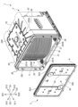
- FIG. 1 is an exploded perspective view showing substrates W stored in a substrate storage container 1 according to an embodiment of the present invention.
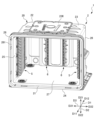
- 2 is a perspective view showing a container body 2 in which no substrates W are stored.
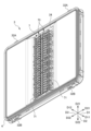
- FIG. 2 is a perspective view showing the cover 3 with the front retainer 7 attached thereto.
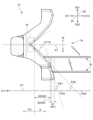
- FIG. 11 is a partial front view (as viewed in the forward direction D11) showing a cover side substrate support portion 73 of the front retainer 7.
- FIG. FIG. 4B is a partially enlarged view of FIG. 4A. This is a cross-sectional view taken along line AA shown in FIG. 4A.
- FIG. 1 is an exploded perspective view showing a state in which substrates W are stored in a substrate storage container 1 according to an embodiment of the present invention.
- FIG. 2 is a perspective view showing a container body 2 in which substrates W are not stored.
- FIG. 3 is a perspective view showing a lid body 3 with a front retainer 7 attached.
- FIG. 4A is a partial front view (viewed in the forward direction D11) showing the lid body side substrate support portion 73 of the front retainer 7.
- FIG. 4B is a partial enlarged view of FIG. 4A.
- FIG. 5 is a cross-sectional view taken along line A-A shown in FIG. 4A.
- the direction from the container body 2 to the lid 3 is defined as the front direction D11
- the opposite direction is defined as the rear direction D12
- the direction from the lower wall 24 to the upper wall 23 is defined as the upward direction D21
- the opposite direction is defined as the downward direction D22
- the direction from the second side wall 26 to the first side wall 25 is defined as the leftward direction D31
- the opposite direction is defined as the rightward direction D32, and these are defined as the left-right direction D3 or lateral direction D3.
- “Direction" may also be called "side.”
- the substrates W stored in the substrate storage container 1 are disk-shaped silicon wafers, glass wafers, sapphire wafers, etc., and are thin wafers used in industry.
- the substrates W are silicon wafers with a diameter of 200 mm to 450 mm.
- the substrate storage container 1 is for storing substrates W made of silicon wafers as described above, and has a container body 2, a lid 3, a side substrate support portion 5, a rear substrate support portion 6, and a front retainer 7 having a lid side substrate support portion 73.
- the container body 2 has a container body opening 21 formed at one end on the front side D11 and a cylindrical wall portion 20 with the other end on the rear side D12 closed.
- a substrate storage space 27 is formed within the container body 2.
- the substrate storage space 27 is surrounded by the wall portion 20.
- a lateral substrate support portion 5 is disposed in the portion of the wall portion 20 that forms the substrate storage space 27.
- a plurality of substrates W can be stored in the substrate storage space 27.
- the side substrate support parts 5 are provided on the wall part 20 in the substrate storage space 27 so as to form a pair in the left-right direction D3.
- the side substrate support parts 5 abut against the sides of the edges of the substrates W, thereby supporting the sides of the edges of the substrates W while arranging adjacent substrates W in the up-down direction D2 in parallel with a predetermined distance between them.
- a rear substrate support part 6 is provided at the rear side (rear side D12) of the container body 2.
- the rear substrate support portion 6 is provided on the wall portion 20 so as to pair with the front retainer 7 inside the substrate storage space 27. When the container body opening 21 is closed by the lid body 3, the rear substrate support portion 6 is able to support the rear portions of the edges of the substrates W by abutting against the rear portions of the edges of the substrates W.
- the lid body 3 is detachable from the opening periphery 28 that forms the container body opening 21, and is capable of closing the container body opening 21.
- the front retainer 7 is provided on a portion of the lid body 3 that faces the substrate storage space 27 when the container body opening 21 is closed by the lid body 3.
- the front retainer 7 is disposed inside the substrate storage space 27 so as to form a pair with the rear substrate support part 6 in the front-to-rear direction D1.
- the front retainer 7 can support the front of the edges of the substrates W by abutting against the edges of the substrates W.
- the front retainer 7 cooperates with the rear substrate support portion 6 to support the substrates W, thereby holding the substrates W in a state in which adjacent substrates W in the vertical direction D2 are spaced apart at a predetermined distance and arranged side by side.
- the substrate storage container 1 is basically symmetrical, and any description of one side applies or is applicable to the other side.
- the wall portion 20 of the container body 2 has a back wall 22, an upper wall 23, a lower wall 24, a first side wall 25 and a second side wall 26.
- the back wall 22, the upper wall 23, the lower wall 24, the first side wall 25 and the second side wall 26 are made of a plastic material or the like, and in this embodiment, are integrally molded from polycarbonate.
- the first side wall 25 and the second side wall 26 face each other in the left-right direction D3, and the upper wall 23 and the lower wall 24 face each other in the up-down direction D2.
- the rear end of the upper wall 23, the rear end of the lower wall 24, the rear end of the first side wall 25, and the rear end of the second side wall 26 are all connected to the rear wall 22.
- the front end of the upper wall 23, the front end of the lower wall 24, the front end of the first side wall 25, and the front end of the second side wall 26 are positioned opposite the rear wall 22, and constitute an opening periphery 28 that forms the container body opening 21, which is approximately rectangular in shape.
- the opening periphery 28 is provided at one end of the container body 2, and the rear wall 22 is located at the other end of the container body 2.
- the outer shape of the container body 2 formed by the outer surfaces of the walls 20 is box-shaped.
- the inner surfaces of the walls 20, i.e., the inner surface of the rear wall 22, the inner surface of the upper wall 23, the inner surface of the lower wall 24, the inner surface of the first side wall 25, and the inner surface of the second side wall 26, form a substrate storage space 27 surrounded by these.
- the container body opening 21 formed at the opening periphery 28 is surrounded by the walls 20 and communicates with the substrate storage space 27 formed inside the container body 2. A maximum of 25 substrates W can be stored in the substrate storage space 27.
- latch engagement recesses 231A, 231B, 241A, and 241B recessed toward the outside of the board storage space 27 are formed in the upper wall 23 and the lower wall 24 near the opening periphery 28.
- a total of four latch engagement recesses 231A, 231B, 241A, and 241B are formed, one each near the left and right ends of the upper wall 23 and the lower wall 24.
- a flange fixing portion (not shown) and ribs 235A, 235B are integrally formed with the upper wall 23 on the outer surface of the upper wall 23.
- the flange fixing portion (not shown) is disposed in the center of the upper wall 23.
- a top flange 236 is fixed to the flange fixing portion (not shown).
- the top flange 236 is disposed in the center of the upper wall 23.
- the top flange 236 is a member that is hung and suspended on the substrate storage container 1 when suspending the substrate storage container 1 in an AMHS (automated wafer transport system), PGV (wafer substrate transport vehicle), etc.
- Multiple ribs 235A extend from the top flange 236 generally in the left direction D31 and the right direction D32.
- Multiple ribs 235B extend from the top flange 236 in the forward direction D11, and multiple ribs 235B extend from the top flange 236 in the rearward direction D12.
- the lid body 3 is provided with a latch mechanism.
- the latch mechanism is provided near both the left and right ends of the lid body 3, and as shown in Figures 1 to 3, has two upper latch portions 32A that can protrude in an upward direction D21 from the top edge of the lid body 3, and two lower latch portions 32B that can protrude in a downward direction D22 from the bottom edge of the lid body 3.
- the two upper latch portions 32A are located near both the left and right ends of the top edge of the lid body 3, and the two lower latch portions 32B are located near both the left and right ends of the bottom edge of the lid body 3.
- An operating portion 33 is provided on the outer surface of the lid body 3.
- the upper latch portion 32A and the lower latch portion 32B can be made to protrude from the upper and lower edges of the lid body 3, or can be made not to protrude from the upper and lower edges.
- the upper latch portion 32A protrudes in the upward direction D21 from the upper edge of the lid body 3 and engages with the latch engagement recesses 231A, 231B of the container body 2
- the lower latch portion 32B protrudes in the downward direction D22 from the lower edge of the lid body 3 and engages with the latch engagement recesses 241A, 241B of the container body 2, thereby fixing the lid body 3 to the opening periphery 28 of the container body 2.
- a recess 34 is formed on the inside (rear side D12) of the lid body 30, recessed toward the outside (front side D11) of the board storage space 27.
- the front retainer 7 is fixed in the recess 34.
- the lid body 3 has a generally rectangular shape that generally matches the shape of the opening periphery 28 of the container body 2.
- the lid body 3 is detachable from the opening periphery 28 of the container body 2, and when the lid body 3 is attached to the opening periphery 28, the lid body 3 can close the container body opening 21.
- An annular sealing member 4 is attached to the inner surface of the lid body 3 (the back surface of the lid body 3 shown in FIG. 1) that faces the surface (sealing surface 281) of the step formed in a position immediately behind the opening edge of the opening periphery 28 in the direction D12 when the lid body 3 is closing the container body opening 21.
- the seal member 4 When the lid 3 is attached to the opening periphery 28, the seal member 4 is sandwiched between the sealing surface 281 and the opposing peripheral portion that constitutes the inner surface of the lid 3 and elastically deforms, and the lid 3 closes the container body opening 21 in a sealed state.
- the substrate W By removing the lid 3 from the opening periphery 28, the substrate W can be inserted and removed from the substrate storage space 27 inside the container body 2.
- the front retainer 7 has a cover-side board support part 73, legs 72, and a vertical frame 71.
- the cover-side board support parts 73 corresponding to the same board W are connected in the left-right direction D3 via the legs 72.
- Two lid body side board support parts 73 are arranged in pairs at a predetermined distance apart in the left-right direction D3.
- the two lid body side board support parts 73 arranged in pairs in this way are arranged in parallel in the up-down direction D2 in 25 pairs, and each is supported by an elastically deformable leg part 72.
- the leg part 72 connects the two lid body side board support parts 73, 73 arranged in the horizontal direction D3.
- the leg part 72 also extends outward in the horizontal direction D3 from the two lid body side board support parts 73, 73 arranged in pairs so as to be spaced apart from each other.
- a vertical frame 71 extending parallel to the up-down direction D2 is integrally molded with the leg part 72 at the outer end of the leg part 72 in the horizontal direction D3.
- the cover-side board support portion 73 has an upper inclined surface 76 and a lower inclined surface 77 that form a V-shaped groove 74 that is a recessed groove that is spaced apart from the center of the board storage space 27.
- Figures 4B and 5 show the cover-side board support portion 73 on the right side D32.
- the upper inclined surface 76 abuts against the edge of the front surface (top surface) of the substrate W when the container body opening 21 is closed by the lid 3.
- the lower inclined surface 77 abuts against the edge of the back surface (bottom surface) of the substrate W.
- the upper inclined surface 76 is configured as an inclined surface that extends at an angle so as to approach the center of the substrate storage space 27 in the front-to-rear direction D1 as it progresses in the upward direction D21.
- the upper inclined surface 76 is configured as an inclined surface that extends at an angle so as to approach the downward direction D22 as it progresses in the forward direction D11.
- the lower inclined surface 77 is configured as an inclined surface that extends at an angle so as to move away from the center of the substrate storage space 27 in the front-to-rear direction D1 as it progresses in the upward direction D21. From another perspective, the lower inclined surface 77 is configured as an inclined surface that extends at an angle so as to move toward the upward direction D21 as it progresses in the forward direction D11.
- the upper inclined surface 76 and the lower inclined surface 77 form a V-shaped groove 74 that is a recessed groove that is recessed away from the center of the substrate storage space 27.
- the upper inclined surface 76 and the lower inclined surface 77 are abutted by the edge of the front surface of the substrate W and the edge of the back surface of the substrate W, respectively, when the container body opening 21 is closed by the lid 3.
- the frontmost portions of the upper inclined surface 76 and the lower inclined surface 77 function as a clamping portion 78 that clamps the edges of multiple substrates W.
- the angle between the upper inclined surface 76 and the lower inclined surface 77 in the clamping portion 78, and the angle ⁇ (induced inclination angle) of the lower inclined surface 77 with respect to a virtual plane P7 (also called the "horizontal plane P7") perpendicular to the vertical direction D2 are small.
- the lower inclined surface 77 has a clamping surface 775 that forms the clamping portion 78, and a guide surface 8 that is located rearward D12 from the clamping surface 775 and guides the substrate W while sliding it toward the clamping portion 78. If the priority is placed on the function of transferring the substrate W to the V-shaped groove 74, it is preferable that the guide inclination angle ⁇ of the guide surface 8 is large, whereas if the priority is placed on the ability of the substrate W to rise up on the guide surface 8, it is preferable that the guide inclination angle ⁇ of the guide surface 8 is small (details will be described later).
- the guide inclination angle ⁇ ( ⁇ 81, ⁇ 82) of the guide surface 8 that is inclined relative to the forward direction D11 (horizontal plane P7) decreases in multiple stages.
- the guide surface 8 has a first guide surface 81 on the rear side D12, a second guide surface 82 located on the front side D11 of the first guide surface 81, and a transition portion 83 located between the first guide surface 81 and the second guide surface 82.
- the first guide surface 81, the second guide surface 82, and the clamping surface 775 are straight planes.
- the transition portion 83 has a shape that smoothly connects the first guide surface 81 and the second guide surface 82.
- the angle ⁇ 82 that the second guide surface 82 makes with respect to the horizontal plane P7 is smaller than the angle ⁇ 81 that the first guide surface 81 makes with respect to the horizontal plane P7.
- the guide inclination angle ⁇ that is inclined with respect to the forward direction D11 (horizontal plane P7) on the guide surface 8 is reduced in two stages ( ⁇ 82 ⁇ 81).
- the angle ⁇ 775 that the clamping surface 775 makes with respect to the horizontal plane P7 is smaller than the angle ⁇ 82 that the second guide surface 82 makes with respect to the horizontal plane P7 ( ⁇ 775 ⁇ 82).
- the angle ⁇ 81 of the first guide surface 81 is, for example, 50 to 80 degrees.
- the angle ⁇ 82 of the second guide surface 82 is, for example, 30 to 45 degrees.
- the angle difference ( ⁇ 81- ⁇ 82) between the angle ⁇ 81 of the first guide surface 81 and the angle ⁇ 82 of the second guide surface 82 is 5 to 50 degrees.
- the length t82 of the second guide surface 82 is longer than the length t81 of the first guide surface 81.
- the length t82 of the second guide surface 82 is, for example, 2 to 3.3 mm.
- the length t81 of the first guide surface 81 is, for example, 0.3 to 1 mm.
- the difference between the length t82 of the second guide surface 82 and the length t81 of the first guide surface 81 (t82-t81) is, for example, 1 to 3 mm.
- the length t83 of the transition portion 83 is, for example, 0.3 to 0.8 mm.
- the area S82 of the second guide surface 82 is larger than the area S81 of the first guide surface 81.
- the difference (S82-S81) between the area S82 of the second guide surface 82 and the area S81 of the first guide surface 81 is, for example, 10 to 40 mm2 .
- a virtual plane P7 (horizontal plane P7) perpendicular to the vertical direction D2 passes through one or both of the lid body side substrate support parts 73 located on the upper side D21 and the lid body side substrate support parts 73 located on the lower side D22.
- the virtual plane P7 can also be said to be the reference direction of the direction in which the substrate W spreads (extends).
- the virtual plane P7 passing only through the lid body side substrate support parts 73 located on the upper side D21 is shown as a virtual plane P71.
- the virtual plane P7 passing only through the lid body side substrate support parts 73 located on the lower side D22 is shown as a virtual plane P72.
- the virtual plane P7 passing through both the lid body side substrate support parts 73 located on the upper side D21 and the lid body side substrate support parts 73 located on the lower side D22 is shown as a virtual plane P70.
- the lower edge 772 of the lower inclined surface 77 of the lid side substrate support portion 73 located on the upper side D21 and the upper edge 761 of the upper inclined surface 76 of the lid side substrate support portion 73 located on the lower side D22 are parallel to each other with a gap between them.
- the lower edge 772 of the lower inclined surface 77 of the lid side substrate support portion 73 located on the upper side D21 and the upper edge 761 of the upper inclined surface 76 of the lid side substrate support portion 73 located on the lower side D22 are inclined toward the downward direction D22 as they move inward in the horizontal direction D3.
- the lower edge 772 of the lower inclined surface 77 of the lid side substrate support portion 73 located on the upper side D21 and the upper edge 761 of the upper inclined surface 76 of the lid side substrate support portion 73 located on the lower side D22 are approximately parallel to the horizontal direction D3 on both sides of the horizontal direction D3, and are inclined toward the downward direction D22 as they move inward in the horizontal direction D3 at the center of the horizontal direction D3.
- the substrate storage container 1 according to the embodiment of the above configuration can provide the following effects.
- the substrate storage container 1 of the embodiment comprises a cylindrical wall portion 20 having a container body opening 21 formed at one end on the front side D11 and the other end on the rear side D12 closed, the container body 2 having a substrate storage space 27 formed by the inner surface of the wall portion 20 that is capable of storing a plurality of substrates W and communicates with the container body opening 21, a lid body 3 that is detachable from the container body opening 21 and capable of closing the container body opening 21, and a portion of the lid body 3 that is connected to the substrate storage space 27 when the container body opening 21 is closed by the lid body 3.
- the container body opening 21 is provided with: a lid-side substrate support part 73 disposed at an opposing portion and capable of supporting edges of the plurality of substrates W when the container body opening 21 is closed by the lid 3; and a rear-side substrate support part 6 disposed in the substrate storage space 27 to form a pair with the lid-side substrate support part 73 and capable of supporting edges of the plurality of substrates W, and supporting the plurality of substrates W in a state in which their edges are aligned in the vertical direction D2 in cooperation with the lid-side substrate support part 73 when the container body opening 21 is closed by the lid 3.
- the lid-side substrate support part 73 has an upper inclined surface 76 and a lower inclined surface 77 which form a V-shaped groove 74 which is a recessed groove recessed away from the center of the substrate storage space 27, and the frontmost portions of the upper inclined surface 76 and the lower inclined surface 77 function as a clamping part 78 which clamps the edges of the plurality of substrates W.
- the lower inclined surface 77 has a clamping surface 775 that forms the clamping portion 78, and a guide surface 8 that is located rearward D12 from the clamping surface 775 and guides the substrate W while sliding it toward the clamping portion 78, and the guide inclination angle ⁇ of the guide surface 8 with respect to the forward direction D11 decreases in multiple stages.
- the position of the lower end of the rear side D12 of the lower inclined surface 77 is located as close to the lower side D22 as possible. However, if an attempt is made to position the lower end of the rear side D12 of the lower inclined surface 77 on the lower side D22, the dimension of the lower inclined surface 77 in the up-down direction D2 becomes larger, and the guided inclination angle ⁇ at which the guided surface 8 is inclined relative to the forward direction D11 becomes larger. If the guided inclination angle ⁇ of the guided surface 8 is large, the tendency of the substrate W to rise up on the guided surface 8 decreases.
- the guided inclination angle ⁇ at which the guided surface 8 is inclined relative to the forward direction D11 is reduced in multiple stages. Therefore, by increasing the guide inclination angle ⁇ ( ⁇ 81) of the rear side D12 of the guide surface 8 and positioning the lower end of the rear side D12 of the lower inclined surface 77 as close to the lower side D22 as possible, the function of transferring the substrate W to the V-shaped groove 74 can be improved, while the guide inclination angle ⁇ of the front side D11 of the guide surface 8 can be reduced ( ⁇ 82 ⁇ 81), improving the ability of the substrate W to rise on the guide surface 8. In other words, it is possible to achieve both the ability to transfer the substrate W to the V-shaped groove 74 and the ability of the substrate W to rise on the guide surface 8.
- the guide surface 8 has a first guide surface 81 on the rear side D12 and a second guide surface 82 located on the front side D11 of the first guide surface 81, and in the front-rear direction D1, the length t82 of the second guide surface 82 is longer than the length t81 of the first guide surface 81. Therefore, according to the embodiment, the longer length t82 of the second guide surface 82 can improve the sliding property of the substrate W on the guide surface 8.
- the area S82 of the second guide surface 82 is larger than the area S81 of the first guide surface 81. Therefore, according to the embodiment, the large area S82 of the second guide surface 82 can improve the sliding property of the substrate W on the guide surface 8.
- the imaginary plane P7 perpendicular to the vertical direction D2 passes through one or both of the lid side substrate support parts 73 located on the upper side D21 and the lid side substrate support parts 73 located on the lower side D22. Therefore, according to the embodiment, it is possible to prevent the substrate W from being inserted between the lower edge 772 of the lower inclined surface 77 of the lid side substrate support part 73 located on the upper side D21 and the upper edge 761 of the upper inclined surface 76 of the lid side substrate support part 73 located on the lower side D22, which would cause the substrate W to be unable to be supported by the lid side substrate support part 73.
- the guiding inclination angle ⁇ of the guiding surface 8 with respect to the forward direction D11 is reduced in two stages ( ⁇ 81> ⁇ 82).
- the guiding inclination angle ⁇ may be reduced in three stages or more, for example, three to five stages.
- the shapes of the container body 2 and the lid body 3, and the number and dimensions of the substrates W that can be stored in the container body 2 are not limited to those in this embodiment.
Landscapes
- Packaging Frangible Articles (AREA)
- Container, Conveyance, Adherence, Positioning, Of Wafer (AREA)
Abstract
La présente invention porte sur un récipient de stockage de substrat 1 qui comprend : un corps de récipient 2 ; un corps de couvercle 3 ; une partie de support de substrat côté corps de couvercle 73 apte à supporter une partie de bord d'une pluralité de substrats W ; et une partie de support de substrat côté arrière 6 qui est disposée de manière à former une paire avec la partie de support de substrat côté corps de couvercle 73 et qui supporte la partie de bord de la pluralité de substrats W en coopération avec la partie de support de substrat côté corps de couvercle 73 lorsqu'une partie d'ouverture de corps de récipient 21 est fermée par le corps de couvercle 3. La partie de support de substrat côté corps de couvercle 73 a une surface inclinée côté supérieur 76 et une surface inclinée côté inférieur 77 qui forment une rainure en forme de V 74, qui est une rainure évidée enfoncée à l'opposé du centre d'un espace de stockage de substrat 27. Une partie la plus en avant de la surface inclinée côté supérieur 76 et de la surface inclinée côté inférieur 77 fonctionne comme une partie de maintien 78 pour maintenir la partie de bord de la pluralité de substrats W. La surface inclinée côté inférieur 77 a une surface de maintien 775 formant la partie de maintien 78 et une surface de guidage 8 qui est située vers l'arrière D12 à partir de la surface de maintien 775 et qui guide les substrats W vers la partie de maintien 78 tout en amenant les substrats W à coulisser. Un angle d'inclinaison de guidage θ, duquel la surface de guidage 8 est inclinée par rapport à une direction avant D11, diminue en de multiples étapes.
Priority Applications (5)
| Application Number | Priority Date | Filing Date | Title |
|---|---|---|---|
| CN202380098079.3A CN121100400A (zh) | 2023-06-09 | 2023-06-09 | 基板收纳容器 |
| JP2025525915A JPWO2024252672A1 (fr) | 2023-06-09 | 2023-06-09 | |
| PCT/JP2023/021559 WO2024252672A1 (fr) | 2023-06-09 | 2023-06-09 | Récipient de stockage de substrat |
| KR1020257039870A KR20260020094A (ko) | 2023-06-09 | 2023-06-09 | 기판수납용기 |
| TW113121297A TW202448781A (zh) | 2023-06-09 | 2024-06-07 | 基板收納容器 |
Applications Claiming Priority (1)
| Application Number | Priority Date | Filing Date | Title |
|---|---|---|---|
| PCT/JP2023/021559 WO2024252672A1 (fr) | 2023-06-09 | 2023-06-09 | Récipient de stockage de substrat |
Publications (1)
| Publication Number | Publication Date |
|---|---|
| WO2024252672A1 true WO2024252672A1 (fr) | 2024-12-12 |
Family
ID=93795858
Family Applications (1)
| Application Number | Title | Priority Date | Filing Date |
|---|---|---|---|
| PCT/JP2023/021559 Ceased WO2024252672A1 (fr) | 2023-06-09 | 2023-06-09 | Récipient de stockage de substrat |
Country Status (5)
| Country | Link |
|---|---|
| JP (1) | JPWO2024252672A1 (fr) |
| KR (1) | KR20260020094A (fr) |
| CN (1) | CN121100400A (fr) |
| TW (1) | TW202448781A (fr) |
| WO (1) | WO2024252672A1 (fr) |
Citations (4)
| Publication number | Priority date | Publication date | Assignee | Title |
|---|---|---|---|---|
| JPH01129836U (fr) * | 1988-02-25 | 1989-09-04 | ||
| JP2002353301A (ja) * | 2001-05-30 | 2002-12-06 | Shin Etsu Polymer Co Ltd | 精密基板収納容器及びその押さえ部材 |
| JP2008135434A (ja) * | 2006-11-27 | 2008-06-12 | Shin Etsu Polymer Co Ltd | 基板収納容器 |
| WO2018185894A1 (fr) * | 2017-04-05 | 2018-10-11 | ミライアル株式会社 | Récipient de stockage de carte |
-
2023
- 2023-06-09 JP JP2025525915A patent/JPWO2024252672A1/ja active Pending
- 2023-06-09 KR KR1020257039870A patent/KR20260020094A/ko active Pending
- 2023-06-09 WO PCT/JP2023/021559 patent/WO2024252672A1/fr not_active Ceased
- 2023-06-09 CN CN202380098079.3A patent/CN121100400A/zh active Pending
-
2024
- 2024-06-07 TW TW113121297A patent/TW202448781A/zh unknown
Patent Citations (4)
| Publication number | Priority date | Publication date | Assignee | Title |
|---|---|---|---|---|
| JPH01129836U (fr) * | 1988-02-25 | 1989-09-04 | ||
| JP2002353301A (ja) * | 2001-05-30 | 2002-12-06 | Shin Etsu Polymer Co Ltd | 精密基板収納容器及びその押さえ部材 |
| JP2008135434A (ja) * | 2006-11-27 | 2008-06-12 | Shin Etsu Polymer Co Ltd | 基板収納容器 |
| WO2018185894A1 (fr) * | 2017-04-05 | 2018-10-11 | ミライアル株式会社 | Récipient de stockage de carte |
Also Published As
| Publication number | Publication date |
|---|---|
| JPWO2024252672A1 (fr) | 2024-12-12 |
| TW202448781A (zh) | 2024-12-16 |
| CN121100400A (zh) | 2025-12-09 |
| KR20260020094A (ko) | 2026-02-10 |
Similar Documents
| Publication | Publication Date | Title |
|---|---|---|
| CN102017118B (zh) | 保持器及包括保持器的基板收纳容器 | |
| CN101855716B (zh) | 保持器以及基板收纳容器 | |
| TWI878536B (zh) | 基板收納容器 | |
| JP6177248B2 (ja) | 基板収納容器 | |
| JP7562657B2 (ja) | 基板収納容器 | |
| WO2014080454A1 (fr) | Récipient de stockage de plaquettes | |
| TW201838042A (zh) | 基板收納容器 | |
| WO2013183138A1 (fr) | Récipient de logement de substrat doté d'une fonction d'absorption d'impact | |
| TW201512060A (zh) | 基板收納容器 | |
| JP4965472B2 (ja) | 処理治具用の収納容器 | |
| WO2024252672A1 (fr) | Récipient de stockage de substrat | |
| WO2024247264A1 (fr) | Récipient de stockage de substrat | |
| TWI431716B (zh) | A storage box for handling jigs | |
| JP2015053329A (ja) | 基板収納容器 | |
| WO2014057573A1 (fr) | Réceptacle de stockage de substrats empêchant la salissure d'une partie maintien de substrats côté corps de couvercle | |
| KR102942671B1 (ko) | 기판수납용기 및 그 뚜껑 | |
| WO2024247263A1 (fr) | Récipient de stockage de substrat | |
| JP2013120896A (ja) | 薄板収納容器 | |
| WO2024241560A1 (fr) | Récipient de stockage de substrat | |
| WO2025109707A1 (fr) | Récipient de stockage de substrat | |
| WO2026083709A1 (fr) | Récipient de stockage de substrats | |
| WO2026047841A1 (fr) | Récipient de stockage de substrat | |
| JP5279372B2 (ja) | 処理治具用の収納ケース | |
| JP2016058629A (ja) | 基板収納容器 | |
| JP2009043943A (ja) | 処理治具用の収納ケース |
Legal Events
| Date | Code | Title | Description |
|---|---|---|---|
| 121 | Ep: the epo has been informed by wipo that ep was designated in this application |
Ref document number: 23940010 Country of ref document: EP Kind code of ref document: A1 |
|
| ENP | Entry into the national phase |
Ref document number: 2025525915 Country of ref document: JP Kind code of ref document: A |
|
| WWE | Wipo information: entry into national phase |
Ref document number: 2025525915 Country of ref document: JP |
|
| NENP | Non-entry into the national phase |
Ref country code: DE |