WO2024252672A1 - 基板収納容器 - Google Patents
基板収納容器 Download PDFInfo
- Publication number
- WO2024252672A1 WO2024252672A1 PCT/JP2023/021559 JP2023021559W WO2024252672A1 WO 2024252672 A1 WO2024252672 A1 WO 2024252672A1 JP 2023021559 W JP2023021559 W JP 2023021559W WO 2024252672 A1 WO2024252672 A1 WO 2024252672A1
- Authority
- WO
- WIPO (PCT)
- Prior art keywords
- lid
- substrate support
- guide surface
- container body
- substrates
- Prior art date
- Legal status (The legal status is an assumption and is not a legal conclusion. Google has not performed a legal analysis and makes no representation as to the accuracy of the status listed.)
- Ceased
Links
Images


Classifications
-
- H—ELECTRICITY
- H10—SEMICONDUCTOR DEVICES; ELECTRIC SOLID-STATE DEVICES NOT OTHERWISE PROVIDED FOR
- H10P—GENERIC PROCESSES OR APPARATUS FOR THE MANUFACTURE OR TREATMENT OF DEVICES COVERED BY CLASS H10
- H10P72/00—Handling or holding of wafers, substrates or devices during manufacture or treatment thereof
- H10P72/10—Handling or holding of wafers, substrates or devices during manufacture or treatment thereof using carriers specially adapted therefor, e.g. front opening unified pods [FOUP]
- H10P72/19—Handling or holding of wafers, substrates or devices during manufacture or treatment thereof using carriers specially adapted therefor, e.g. front opening unified pods [FOUP] closed carriers
- H10P72/1921—Handling or holding of wafers, substrates or devices during manufacture or treatment thereof using carriers specially adapted therefor, e.g. front opening unified pods [FOUP] closed carriers characterised by substrate supports
-
- H—ELECTRICITY
- H10—SEMICONDUCTOR DEVICES; ELECTRIC SOLID-STATE DEVICES NOT OTHERWISE PROVIDED FOR
- H10P—GENERIC PROCESSES OR APPARATUS FOR THE MANUFACTURE OR TREATMENT OF DEVICES COVERED BY CLASS H10
- H10P72/00—Handling or holding of wafers, substrates or devices during manufacture or treatment thereof
- H10P72/10—Handling or holding of wafers, substrates or devices during manufacture or treatment thereof using carriers specially adapted therefor, e.g. front opening unified pods [FOUP]
- H10P72/19—Handling or holding of wafers, substrates or devices during manufacture or treatment thereof using carriers specially adapted therefor, e.g. front opening unified pods [FOUP] closed carriers
- H10P72/1922—Handling or holding of wafers, substrates or devices during manufacture or treatment thereof using carriers specially adapted therefor, e.g. front opening unified pods [FOUP] closed carriers characterised by the construction of the closed carrier
Definitions
- the present invention relates to a substrate storage container used for storing, transporting, shipping, etc., substrates such as semiconductor wafers.
- Patent Document 1 As a substrate storage container for storing and transporting substrates made of semiconductor wafers, a container having a container body and a lid has been known (see, for example, Patent Document 1).
- One end of the container body has an opening periphery where the container body opening is formed.
- the other end of the container body has a closed cylindrical wall.
- a substrate storage space is formed within the container body.
- the substrate storage space is surrounded by the wall and is capable of storing multiple substrates.
- the lid is detachable from the opening periphery and is capable of closing the container body opening.
- the side substrate support portions are provided on the wall portions in a pair in the left-right direction within the substrate storage space. When the container body opening is not closed by the lid, the side substrate support portions are capable of supporting the edges of multiple substrates in a state where adjacent substrates are spaced apart from each other in the vertical direction and arranged in parallel at a predetermined distance from each other.
- a front retainer is provided on the portion of the lid that faces the substrate storage space when the container body opening is closed.
- the front retainer has a lid-side substrate support portion that directly contacts the substrate to support it, and a lid-side leg portion that supports the lid-side substrate support portion, and is capable of supporting the edges of multiple substrates when the container body opening is closed by the lid.
- a rear-side substrate support portion is provided on the wall portion so as to form a pair with the front retainer. The rear-side substrate support portion is capable of supporting the edges of multiple substrates.
- the rear-side substrate support portion cooperates with the front retainer to support the multiple substrates, thereby holding the multiple substrates in a state in which adjacent substrates are spaced apart from each other at a predetermined interval in the vertical direction and aligned in parallel.
- the cover-side substrate support portion has upper and lower inclined surfaces that form a V-shaped groove that is recessed (toward the front) away from the center of the substrate storage space.
- the frontmost portions of the upper and lower inclined surfaces function as clamping portions that clamp the edges of multiple substrates.
- the substrate When the lid is used to close the opening of the container body, the substrate is easily guided poorly into the clamping portion of the V-shaped groove in the lid-side substrate support portion.
- the edge of the substrate is supported by the lateral substrate support portion.
- the substrate hits the lower inclined surface of the lid-side substrate support portion, then rises up the lower inclined surface and is guided (introduced) into the clamping portion of the V-shaped groove.
- the substrate may not smoothly rise up the lower inclined surface of the lid-side substrate support part and may not be smoothly guided into the clamping portion of the V-shaped groove.
- the present invention aims to provide a substrate storage container that can prevent the occurrence of poor substrate insertion in the substrate support portion on the lid side.
- the first invention relates to a container body having a cylindrical wall portion with a container body opening formed at one end on the front side and the other end on the rear side closed, the inner surface of the wall portion forming a substrate storage space capable of storing a plurality of substrates and communicating with the container body opening, a lid body that is detachable from the container body opening and capable of closing the container body opening, a lid body side substrate support portion that is a part of the lid body and is arranged in a portion facing the substrate storage space when the container body opening is closed by the lid body and is capable of supporting the edges of the plurality of substrates when the container body opening is closed by the lid body, and a substrate support portion that is arranged in a pair with the lid body side substrate support portion within the substrate storage space and is capable of supporting the edges of the plurality of substrates, the lid body being attached to the substrate storage space and being attached to the substrate storage space and being connected to the substrate storage space.
- the container when the container body opening is closed, the container is provided with a rear-side substrate support portion that cooperates with the lid-side substrate support portion to support the multiple substrates with the edges of the multiple substrates aligned in the vertical direction
- the lid-side substrate support portion has an upper inclined surface and a lower inclined surface that form a V-shaped groove that is a recessed groove that is recessed away from the center of the substrate storage space, the front-most portions of the upper inclined surface and the lower inclined surface function as a clamping portion that clamps the edges of the multiple substrates
- the lower inclined surface has a clamping surface that forms the clamping portion, and a guide surface that is located behind the clamping surface and guides the substrates while sliding them toward the clamping portion, and the guide inclination angle of the guide surface that is inclined toward the front direction decreases in multiple stages.
- the second invention is a substrate storage container according to (1), in which the guide surface has a first guide surface on the rear side and a second guide surface located in front of the first guide surface, and the length of the second guide surface is longer than the length of the first guide surface in the front-to-rear direction.
- the third aspect of the present invention is a substrate storage capacity according to (2), in which the area of the second guide surface is larger than the area of the first guide surface.
- the fourth invention is a substrate storage container according to any one of (1) to (3), in which, in the vertically adjacent lid-side substrate support parts, an imaginary plane perpendicular to the vertical direction passes through one or both of the lid-side substrate support part located on the upper side and the lid-side substrate support part located on the lower side.
- the fifth invention is a substrate storage container according to any one of (1) to (4), in which, in the vertically adjacent lid-side substrate support parts, when viewed from the front, the lower edge of the lower inclined surface of the lid-side substrate support part located on the upper side and the upper edge of the upper inclined surface of the lid-side substrate support part located on the lower side are parallel to each other with a gap between them, and are inclined downward as they move laterally inward.
- the present invention provides a substrate storage container that can prevent the occurrence of substrate guide failures in the substrate support portion on the lid side.
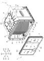
- FIG. 1 is an exploded perspective view showing substrates W stored in a substrate storage container 1 according to an embodiment of the present invention.
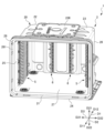
- 2 is a perspective view showing a container body 2 in which no substrates W are stored.
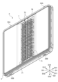
- FIG. 2 is a perspective view showing the cover 3 with the front retainer 7 attached thereto.
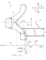
- FIG. 11 is a partial front view (as viewed in the forward direction D11) showing a cover side substrate support portion 73 of the front retainer 7.
- FIG. FIG. 4B is a partially enlarged view of FIG. 4A. This is a cross-sectional view taken along line AA shown in FIG. 4A.
- FIG. 1 is an exploded perspective view showing a state in which substrates W are stored in a substrate storage container 1 according to an embodiment of the present invention.
- FIG. 2 is a perspective view showing a container body 2 in which substrates W are not stored.
- FIG. 3 is a perspective view showing a lid body 3 with a front retainer 7 attached.
- FIG. 4A is a partial front view (viewed in the forward direction D11) showing the lid body side substrate support portion 73 of the front retainer 7.
- FIG. 4B is a partial enlarged view of FIG. 4A.
- FIG. 5 is a cross-sectional view taken along line A-A shown in FIG. 4A.
- the direction from the container body 2 to the lid 3 is defined as the front direction D11
- the opposite direction is defined as the rear direction D12
- the direction from the lower wall 24 to the upper wall 23 is defined as the upward direction D21
- the opposite direction is defined as the downward direction D22
- the direction from the second side wall 26 to the first side wall 25 is defined as the leftward direction D31
- the opposite direction is defined as the rightward direction D32, and these are defined as the left-right direction D3 or lateral direction D3.
- “Direction" may also be called "side.”
- the substrates W stored in the substrate storage container 1 are disk-shaped silicon wafers, glass wafers, sapphire wafers, etc., and are thin wafers used in industry.
- the substrates W are silicon wafers with a diameter of 200 mm to 450 mm.
- the substrate storage container 1 is for storing substrates W made of silicon wafers as described above, and has a container body 2, a lid 3, a side substrate support portion 5, a rear substrate support portion 6, and a front retainer 7 having a lid side substrate support portion 73.
- the container body 2 has a container body opening 21 formed at one end on the front side D11 and a cylindrical wall portion 20 with the other end on the rear side D12 closed.
- a substrate storage space 27 is formed within the container body 2.
- the substrate storage space 27 is surrounded by the wall portion 20.
- a lateral substrate support portion 5 is disposed in the portion of the wall portion 20 that forms the substrate storage space 27.
- a plurality of substrates W can be stored in the substrate storage space 27.
- the side substrate support parts 5 are provided on the wall part 20 in the substrate storage space 27 so as to form a pair in the left-right direction D3.
- the side substrate support parts 5 abut against the sides of the edges of the substrates W, thereby supporting the sides of the edges of the substrates W while arranging adjacent substrates W in the up-down direction D2 in parallel with a predetermined distance between them.
- a rear substrate support part 6 is provided at the rear side (rear side D12) of the container body 2.
- the rear substrate support portion 6 is provided on the wall portion 20 so as to pair with the front retainer 7 inside the substrate storage space 27. When the container body opening 21 is closed by the lid body 3, the rear substrate support portion 6 is able to support the rear portions of the edges of the substrates W by abutting against the rear portions of the edges of the substrates W.
- the lid body 3 is detachable from the opening periphery 28 that forms the container body opening 21, and is capable of closing the container body opening 21.
- the front retainer 7 is provided on a portion of the lid body 3 that faces the substrate storage space 27 when the container body opening 21 is closed by the lid body 3.
- the front retainer 7 is disposed inside the substrate storage space 27 so as to form a pair with the rear substrate support part 6 in the front-to-rear direction D1.
- the front retainer 7 can support the front of the edges of the substrates W by abutting against the edges of the substrates W.
- the front retainer 7 cooperates with the rear substrate support portion 6 to support the substrates W, thereby holding the substrates W in a state in which adjacent substrates W in the vertical direction D2 are spaced apart at a predetermined distance and arranged side by side.
- the substrate storage container 1 is basically symmetrical, and any description of one side applies or is applicable to the other side.
- the wall portion 20 of the container body 2 has a back wall 22, an upper wall 23, a lower wall 24, a first side wall 25 and a second side wall 26.
- the back wall 22, the upper wall 23, the lower wall 24, the first side wall 25 and the second side wall 26 are made of a plastic material or the like, and in this embodiment, are integrally molded from polycarbonate.
- the first side wall 25 and the second side wall 26 face each other in the left-right direction D3, and the upper wall 23 and the lower wall 24 face each other in the up-down direction D2.
- the rear end of the upper wall 23, the rear end of the lower wall 24, the rear end of the first side wall 25, and the rear end of the second side wall 26 are all connected to the rear wall 22.
- the front end of the upper wall 23, the front end of the lower wall 24, the front end of the first side wall 25, and the front end of the second side wall 26 are positioned opposite the rear wall 22, and constitute an opening periphery 28 that forms the container body opening 21, which is approximately rectangular in shape.
- the opening periphery 28 is provided at one end of the container body 2, and the rear wall 22 is located at the other end of the container body 2.
- the outer shape of the container body 2 formed by the outer surfaces of the walls 20 is box-shaped.
- the inner surfaces of the walls 20, i.e., the inner surface of the rear wall 22, the inner surface of the upper wall 23, the inner surface of the lower wall 24, the inner surface of the first side wall 25, and the inner surface of the second side wall 26, form a substrate storage space 27 surrounded by these.
- the container body opening 21 formed at the opening periphery 28 is surrounded by the walls 20 and communicates with the substrate storage space 27 formed inside the container body 2. A maximum of 25 substrates W can be stored in the substrate storage space 27.
- latch engagement recesses 231A, 231B, 241A, and 241B recessed toward the outside of the board storage space 27 are formed in the upper wall 23 and the lower wall 24 near the opening periphery 28.
- a total of four latch engagement recesses 231A, 231B, 241A, and 241B are formed, one each near the left and right ends of the upper wall 23 and the lower wall 24.
- a flange fixing portion (not shown) and ribs 235A, 235B are integrally formed with the upper wall 23 on the outer surface of the upper wall 23.
- the flange fixing portion (not shown) is disposed in the center of the upper wall 23.
- a top flange 236 is fixed to the flange fixing portion (not shown).
- the top flange 236 is disposed in the center of the upper wall 23.
- the top flange 236 is a member that is hung and suspended on the substrate storage container 1 when suspending the substrate storage container 1 in an AMHS (automated wafer transport system), PGV (wafer substrate transport vehicle), etc.
- Multiple ribs 235A extend from the top flange 236 generally in the left direction D31 and the right direction D32.
- Multiple ribs 235B extend from the top flange 236 in the forward direction D11, and multiple ribs 235B extend from the top flange 236 in the rearward direction D12.
- the lid body 3 is provided with a latch mechanism.
- the latch mechanism is provided near both the left and right ends of the lid body 3, and as shown in Figures 1 to 3, has two upper latch portions 32A that can protrude in an upward direction D21 from the top edge of the lid body 3, and two lower latch portions 32B that can protrude in a downward direction D22 from the bottom edge of the lid body 3.
- the two upper latch portions 32A are located near both the left and right ends of the top edge of the lid body 3, and the two lower latch portions 32B are located near both the left and right ends of the bottom edge of the lid body 3.
- An operating portion 33 is provided on the outer surface of the lid body 3.
- the upper latch portion 32A and the lower latch portion 32B can be made to protrude from the upper and lower edges of the lid body 3, or can be made not to protrude from the upper and lower edges.
- the upper latch portion 32A protrudes in the upward direction D21 from the upper edge of the lid body 3 and engages with the latch engagement recesses 231A, 231B of the container body 2
- the lower latch portion 32B protrudes in the downward direction D22 from the lower edge of the lid body 3 and engages with the latch engagement recesses 241A, 241B of the container body 2, thereby fixing the lid body 3 to the opening periphery 28 of the container body 2.
- a recess 34 is formed on the inside (rear side D12) of the lid body 30, recessed toward the outside (front side D11) of the board storage space 27.
- the front retainer 7 is fixed in the recess 34.
- the lid body 3 has a generally rectangular shape that generally matches the shape of the opening periphery 28 of the container body 2.
- the lid body 3 is detachable from the opening periphery 28 of the container body 2, and when the lid body 3 is attached to the opening periphery 28, the lid body 3 can close the container body opening 21.
- An annular sealing member 4 is attached to the inner surface of the lid body 3 (the back surface of the lid body 3 shown in FIG. 1) that faces the surface (sealing surface 281) of the step formed in a position immediately behind the opening edge of the opening periphery 28 in the direction D12 when the lid body 3 is closing the container body opening 21.
- the seal member 4 When the lid 3 is attached to the opening periphery 28, the seal member 4 is sandwiched between the sealing surface 281 and the opposing peripheral portion that constitutes the inner surface of the lid 3 and elastically deforms, and the lid 3 closes the container body opening 21 in a sealed state.
- the substrate W By removing the lid 3 from the opening periphery 28, the substrate W can be inserted and removed from the substrate storage space 27 inside the container body 2.
- the front retainer 7 has a cover-side board support part 73, legs 72, and a vertical frame 71.
- the cover-side board support parts 73 corresponding to the same board W are connected in the left-right direction D3 via the legs 72.
- Two lid body side board support parts 73 are arranged in pairs at a predetermined distance apart in the left-right direction D3.
- the two lid body side board support parts 73 arranged in pairs in this way are arranged in parallel in the up-down direction D2 in 25 pairs, and each is supported by an elastically deformable leg part 72.
- the leg part 72 connects the two lid body side board support parts 73, 73 arranged in the horizontal direction D3.
- the leg part 72 also extends outward in the horizontal direction D3 from the two lid body side board support parts 73, 73 arranged in pairs so as to be spaced apart from each other.
- a vertical frame 71 extending parallel to the up-down direction D2 is integrally molded with the leg part 72 at the outer end of the leg part 72 in the horizontal direction D3.
- the cover-side board support portion 73 has an upper inclined surface 76 and a lower inclined surface 77 that form a V-shaped groove 74 that is a recessed groove that is spaced apart from the center of the board storage space 27.
- Figures 4B and 5 show the cover-side board support portion 73 on the right side D32.
- the upper inclined surface 76 abuts against the edge of the front surface (top surface) of the substrate W when the container body opening 21 is closed by the lid 3.
- the lower inclined surface 77 abuts against the edge of the back surface (bottom surface) of the substrate W.
- the upper inclined surface 76 is configured as an inclined surface that extends at an angle so as to approach the center of the substrate storage space 27 in the front-to-rear direction D1 as it progresses in the upward direction D21.
- the upper inclined surface 76 is configured as an inclined surface that extends at an angle so as to approach the downward direction D22 as it progresses in the forward direction D11.
- the lower inclined surface 77 is configured as an inclined surface that extends at an angle so as to move away from the center of the substrate storage space 27 in the front-to-rear direction D1 as it progresses in the upward direction D21. From another perspective, the lower inclined surface 77 is configured as an inclined surface that extends at an angle so as to move toward the upward direction D21 as it progresses in the forward direction D11.
- the upper inclined surface 76 and the lower inclined surface 77 form a V-shaped groove 74 that is a recessed groove that is recessed away from the center of the substrate storage space 27.
- the upper inclined surface 76 and the lower inclined surface 77 are abutted by the edge of the front surface of the substrate W and the edge of the back surface of the substrate W, respectively, when the container body opening 21 is closed by the lid 3.
- the frontmost portions of the upper inclined surface 76 and the lower inclined surface 77 function as a clamping portion 78 that clamps the edges of multiple substrates W.
- the angle between the upper inclined surface 76 and the lower inclined surface 77 in the clamping portion 78, and the angle ⁇ (induced inclination angle) of the lower inclined surface 77 with respect to a virtual plane P7 (also called the "horizontal plane P7") perpendicular to the vertical direction D2 are small.
- the lower inclined surface 77 has a clamping surface 775 that forms the clamping portion 78, and a guide surface 8 that is located rearward D12 from the clamping surface 775 and guides the substrate W while sliding it toward the clamping portion 78. If the priority is placed on the function of transferring the substrate W to the V-shaped groove 74, it is preferable that the guide inclination angle ⁇ of the guide surface 8 is large, whereas if the priority is placed on the ability of the substrate W to rise up on the guide surface 8, it is preferable that the guide inclination angle ⁇ of the guide surface 8 is small (details will be described later).
- the guide inclination angle ⁇ ( ⁇ 81, ⁇ 82) of the guide surface 8 that is inclined relative to the forward direction D11 (horizontal plane P7) decreases in multiple stages.
- the guide surface 8 has a first guide surface 81 on the rear side D12, a second guide surface 82 located on the front side D11 of the first guide surface 81, and a transition portion 83 located between the first guide surface 81 and the second guide surface 82.
- the first guide surface 81, the second guide surface 82, and the clamping surface 775 are straight planes.
- the transition portion 83 has a shape that smoothly connects the first guide surface 81 and the second guide surface 82.
- the angle ⁇ 82 that the second guide surface 82 makes with respect to the horizontal plane P7 is smaller than the angle ⁇ 81 that the first guide surface 81 makes with respect to the horizontal plane P7.
- the guide inclination angle ⁇ that is inclined with respect to the forward direction D11 (horizontal plane P7) on the guide surface 8 is reduced in two stages ( ⁇ 82 ⁇ 81).
- the angle ⁇ 775 that the clamping surface 775 makes with respect to the horizontal plane P7 is smaller than the angle ⁇ 82 that the second guide surface 82 makes with respect to the horizontal plane P7 ( ⁇ 775 ⁇ 82).
- the angle ⁇ 81 of the first guide surface 81 is, for example, 50 to 80 degrees.
- the angle ⁇ 82 of the second guide surface 82 is, for example, 30 to 45 degrees.
- the angle difference ( ⁇ 81- ⁇ 82) between the angle ⁇ 81 of the first guide surface 81 and the angle ⁇ 82 of the second guide surface 82 is 5 to 50 degrees.
- the length t82 of the second guide surface 82 is longer than the length t81 of the first guide surface 81.
- the length t82 of the second guide surface 82 is, for example, 2 to 3.3 mm.
- the length t81 of the first guide surface 81 is, for example, 0.3 to 1 mm.
- the difference between the length t82 of the second guide surface 82 and the length t81 of the first guide surface 81 (t82-t81) is, for example, 1 to 3 mm.
- the length t83 of the transition portion 83 is, for example, 0.3 to 0.8 mm.
- the area S82 of the second guide surface 82 is larger than the area S81 of the first guide surface 81.
- the difference (S82-S81) between the area S82 of the second guide surface 82 and the area S81 of the first guide surface 81 is, for example, 10 to 40 mm2 .
- a virtual plane P7 (horizontal plane P7) perpendicular to the vertical direction D2 passes through one or both of the lid body side substrate support parts 73 located on the upper side D21 and the lid body side substrate support parts 73 located on the lower side D22.
- the virtual plane P7 can also be said to be the reference direction of the direction in which the substrate W spreads (extends).
- the virtual plane P7 passing only through the lid body side substrate support parts 73 located on the upper side D21 is shown as a virtual plane P71.
- the virtual plane P7 passing only through the lid body side substrate support parts 73 located on the lower side D22 is shown as a virtual plane P72.
- the virtual plane P7 passing through both the lid body side substrate support parts 73 located on the upper side D21 and the lid body side substrate support parts 73 located on the lower side D22 is shown as a virtual plane P70.
- the lower edge 772 of the lower inclined surface 77 of the lid side substrate support portion 73 located on the upper side D21 and the upper edge 761 of the upper inclined surface 76 of the lid side substrate support portion 73 located on the lower side D22 are parallel to each other with a gap between them.
- the lower edge 772 of the lower inclined surface 77 of the lid side substrate support portion 73 located on the upper side D21 and the upper edge 761 of the upper inclined surface 76 of the lid side substrate support portion 73 located on the lower side D22 are inclined toward the downward direction D22 as they move inward in the horizontal direction D3.
- the lower edge 772 of the lower inclined surface 77 of the lid side substrate support portion 73 located on the upper side D21 and the upper edge 761 of the upper inclined surface 76 of the lid side substrate support portion 73 located on the lower side D22 are approximately parallel to the horizontal direction D3 on both sides of the horizontal direction D3, and are inclined toward the downward direction D22 as they move inward in the horizontal direction D3 at the center of the horizontal direction D3.
- the substrate storage container 1 according to the embodiment of the above configuration can provide the following effects.
- the substrate storage container 1 of the embodiment comprises a cylindrical wall portion 20 having a container body opening 21 formed at one end on the front side D11 and the other end on the rear side D12 closed, the container body 2 having a substrate storage space 27 formed by the inner surface of the wall portion 20 that is capable of storing a plurality of substrates W and communicates with the container body opening 21, a lid body 3 that is detachable from the container body opening 21 and capable of closing the container body opening 21, and a portion of the lid body 3 that is connected to the substrate storage space 27 when the container body opening 21 is closed by the lid body 3.
- the container body opening 21 is provided with: a lid-side substrate support part 73 disposed at an opposing portion and capable of supporting edges of the plurality of substrates W when the container body opening 21 is closed by the lid 3; and a rear-side substrate support part 6 disposed in the substrate storage space 27 to form a pair with the lid-side substrate support part 73 and capable of supporting edges of the plurality of substrates W, and supporting the plurality of substrates W in a state in which their edges are aligned in the vertical direction D2 in cooperation with the lid-side substrate support part 73 when the container body opening 21 is closed by the lid 3.
- the lid-side substrate support part 73 has an upper inclined surface 76 and a lower inclined surface 77 which form a V-shaped groove 74 which is a recessed groove recessed away from the center of the substrate storage space 27, and the frontmost portions of the upper inclined surface 76 and the lower inclined surface 77 function as a clamping part 78 which clamps the edges of the plurality of substrates W.
- the lower inclined surface 77 has a clamping surface 775 that forms the clamping portion 78, and a guide surface 8 that is located rearward D12 from the clamping surface 775 and guides the substrate W while sliding it toward the clamping portion 78, and the guide inclination angle ⁇ of the guide surface 8 with respect to the forward direction D11 decreases in multiple stages.
- the position of the lower end of the rear side D12 of the lower inclined surface 77 is located as close to the lower side D22 as possible. However, if an attempt is made to position the lower end of the rear side D12 of the lower inclined surface 77 on the lower side D22, the dimension of the lower inclined surface 77 in the up-down direction D2 becomes larger, and the guided inclination angle ⁇ at which the guided surface 8 is inclined relative to the forward direction D11 becomes larger. If the guided inclination angle ⁇ of the guided surface 8 is large, the tendency of the substrate W to rise up on the guided surface 8 decreases.
- the guided inclination angle ⁇ at which the guided surface 8 is inclined relative to the forward direction D11 is reduced in multiple stages. Therefore, by increasing the guide inclination angle ⁇ ( ⁇ 81) of the rear side D12 of the guide surface 8 and positioning the lower end of the rear side D12 of the lower inclined surface 77 as close to the lower side D22 as possible, the function of transferring the substrate W to the V-shaped groove 74 can be improved, while the guide inclination angle ⁇ of the front side D11 of the guide surface 8 can be reduced ( ⁇ 82 ⁇ 81), improving the ability of the substrate W to rise on the guide surface 8. In other words, it is possible to achieve both the ability to transfer the substrate W to the V-shaped groove 74 and the ability of the substrate W to rise on the guide surface 8.
- the guide surface 8 has a first guide surface 81 on the rear side D12 and a second guide surface 82 located on the front side D11 of the first guide surface 81, and in the front-rear direction D1, the length t82 of the second guide surface 82 is longer than the length t81 of the first guide surface 81. Therefore, according to the embodiment, the longer length t82 of the second guide surface 82 can improve the sliding property of the substrate W on the guide surface 8.
- the area S82 of the second guide surface 82 is larger than the area S81 of the first guide surface 81. Therefore, according to the embodiment, the large area S82 of the second guide surface 82 can improve the sliding property of the substrate W on the guide surface 8.
- the imaginary plane P7 perpendicular to the vertical direction D2 passes through one or both of the lid side substrate support parts 73 located on the upper side D21 and the lid side substrate support parts 73 located on the lower side D22. Therefore, according to the embodiment, it is possible to prevent the substrate W from being inserted between the lower edge 772 of the lower inclined surface 77 of the lid side substrate support part 73 located on the upper side D21 and the upper edge 761 of the upper inclined surface 76 of the lid side substrate support part 73 located on the lower side D22, which would cause the substrate W to be unable to be supported by the lid side substrate support part 73.
- the guiding inclination angle ⁇ of the guiding surface 8 with respect to the forward direction D11 is reduced in two stages ( ⁇ 81> ⁇ 82).
- the guiding inclination angle ⁇ may be reduced in three stages or more, for example, three to five stages.
- the shapes of the container body 2 and the lid body 3, and the number and dimensions of the substrates W that can be stored in the container body 2 are not limited to those in this embodiment.
Landscapes
- Packaging Frangible Articles (AREA)
- Container, Conveyance, Adherence, Positioning, Of Wafer (AREA)
Abstract
基板収納容器1は、容器本体2と、蓋体3と、複数の基板Wの縁部を支持可能な蓋体側基板支持部73と、蓋体側基板支持部73と対をなすように配置され、蓋体3によって容器本体開口部21が閉塞されているときに蓋体側基板支持部73と協働して、複数の基板Wの縁部を支持する奥側基板支持部6と、を備え、蓋体側基板支持部73は、基板収納空間27の中心から離間するように窪んだ凹溝であるV字状溝74を形成する上側傾斜面76及び下側傾斜面77を有し、上側傾斜面76及び下側傾斜面77の最前部は、複数の基板Wの縁部を挟持する挟持部78として機能し、下側傾斜面77は、挟持部78を形成する挟持面775と、挟持面775よりも後ろ側D12に位置し且つ挟持部78へ基板Wをスライドさせながら誘導する誘導面8と、を有し、誘導面8における前方向D11に対して傾斜する誘導傾斜角度θは、複数段階に減少している。
Description
本発明は、半導体ウェーハ等からなる基板を収納、保管、搬送、輸送等する際に使用される基板収納容器に関する。
半導体ウェーハからなる基板を収納して搬送するための基板収納容器としては、容器本体と蓋体とを備える構成のものが、従来より知られている(例えば、特許文献1参照)。
容器本体の一端部は、容器本体開口部が形成された開口周縁部を有する。容器本体の他端部は、閉塞された筒状の壁部を有する。容器本体内には基板収納空間が形成されている。基板収納空間は、壁部により取り囲まれて形成されており、複数の基板を収納可能である。蓋体は、開口周縁部に対して着脱可能であり、容器本体開口部を閉塞可能である。側方基板支持部は、基板収納空間内において左右方向に対をなすように壁部に設けられている。側方基板支持部は、蓋体によって容器本体開口部が閉塞されていないときに、上下方向に隣接する基板同士を所定の間隔で離間させて並列させた状態で、複数の基板の縁部を支持可能である。
蓋体の部分であって容器本体開口部を閉塞しているときに基板収納空間に対向する部分には、フロントリテーナが設けられている。フロントリテーナは、基板に直接当接して基板を支持する蓋体側基板支持部と、蓋体側基板支持部を支持する蓋体側脚部とを有しており、蓋体によって容器本体開口部が閉塞されているときに、複数の基板の縁部を支持可能である。また、フロントリテーナと対をなすようにして、奥側基板支持部が壁部に設けられている。奥側基板支持部は、複数の基板の縁部を支持可能である。奥側基板支持部は、蓋体によって容器本体開口部が閉塞されているときに、フロントリテーナと協働して複数の基板を支持することにより、上下方向に隣接する基板同士を所定の間隔で離間させて並列させた状態で、複数の基板を保持する。
蓋体側基板支持部は、基板収納空間の中心から離間するように(前側に)窪んだ凹溝であるV字状溝を形成する上側傾斜面及び下側傾斜面を有する。上側傾斜面及び下側傾斜面の最前部は、複数の基板の縁部を挟持する挟持部として機能する。
蓋体によって容器本体開口部を閉塞する際に、蓋体側基板支持部におけるV字状溝の挟持部への基板の誘い込み不良が発生しやすい。詳述すると、容器本体を水平に配置した状態(蓋体側基板支持部の下側傾斜面を下側に配置した状態)で、側方基板支持部により基板の縁部を支持させる。その後、蓋体を容器本体の容器本体開口部に接近させていくと、基板は、蓋体側基板支持部の下側傾斜面に突き当たり、その後、下側傾斜面をせり上がり、V字状溝の挟持部に誘い込まれる(導入される)。
しかし、側方基板支持部により支持された基板の(蓋体側基板支持部に対する)位置や角度、基板の厚さや重さによる基板の撓みなどの各種バラツキに起因して、基板が蓋体側基板支持部の下側傾斜面をスムーズにせり上がらずに、V字状溝の挟持部にスムーズに誘い込まれないことがある。
本発明は、蓋体側基板支持部における基板の誘い込み不良の発生を抑制することが可能な基板収納容器を提供することを目的とする。
(1)第1の本発明は、前側の一端部に容器本体開口部が形成され後ろ側の他端部が閉塞された筒状の壁部を備え、前記壁部の内面によって、複数の基板を収納可能であり前記容器本体開口部に連通する基板収納空間が形成された容器本体と、前記容器本体開口部に対して着脱可能であり、前記容器本体開口部を閉塞可能な蓋体と、前記蓋体の部分であって前記蓋体によって前記容器本体開口部が閉塞されているときに前記基板収納空間に対向する部分に配置され、前記蓋体によって前記容器本体開口部が閉塞されているときに、前記複数の基板の縁部を支持可能な蓋体側基板支持部と、前記基板収納空間内において前記蓋体側基板支持部と対をなすように配置され、前記複数の基板の縁部を支持可能であり、前記蓋体によって前記容器本体開口部が閉塞されているときに前記蓋体側基板支持部と協働して、前記複数の基板の縁部を上下方向に並列させた状態で、前記複数の基板を支持する奥側基板支持部と、を備え、前記蓋体側基板支持部は、前記基板収納空間の中心から離間するように窪んだ凹溝であるV字状溝を形成する上側傾斜面及び下側傾斜面を有し、前記上側傾斜面及び前記下側傾斜面の最前部は、前記複数の基板の縁部を挟持する挟持部として機能し、前記下側傾斜面は、前記挟持部を形成する挟持面と、前記挟持面よりも後ろ側に位置し且つ前記挟持部へ前記基板をスライドさせながら誘導する誘導面と、を有し、前記誘導面における前方向に対して傾斜する誘導傾斜角度は、複数段階に減少している、基板収納容器である。
(2)第2の本発明は、前記誘導面は、後ろ側の第1誘導面と、前記第1誘導面の前側に位置する第2誘導面とを有し、前後方向において、前記第2誘導面の長さは前記第1誘導面の長さよりも長い、(1)の基板収納容器である。
(3)第3の本発明は、前記第2誘導面の面積は前記第1誘導面の面積よりも大きい、(2)の基板収納容である。
(4)第4の本発明は、上下方向に隣接する前記蓋体側基板支持部において、上下方向に直交する仮想平面は、上側に位置する前記蓋体側基板支持部又は下側に位置する前記蓋体側基板支持部の一方又は両方を通る、(1)~(3)のいずれかの基板収納容器である。
(5)第5の本発明は、上下方向に隣接する前記蓋体側基板支持部において、前方向に視たときに、上側に位置する前記蓋体側基板支持部の前記下側傾斜面の下端縁と、下側に位置する前記蓋体側基板支持部の前記上側傾斜面の上端縁とは、間隔を空けて並列しており、且つ、横方向の内側に進むにつれて、下方向に向かうように傾斜している、(1)~(4)のいずれかの基板収納容器である。
本発明によれば、蓋体側基板支持部における基板の誘い込み不良の発生を抑制することが可能な基板収納容器を提供することができる。
以下、本発明の実施形態の基板収納容器1について、図面を参照しながら説明する。図1は、本発明の実施形態に係る基板収納容器1に基板Wが収納された様子を示す分解斜視図である。図2は、基板Wが収納されていない容器本体2を示す斜視図である。図3は、フロントリテーナ7が取り付けられた状態の蓋体3を示す斜視図である。図4Aは、フロントリテーナ7の蓋体側基板支持部73を示す部分正面図(前方向D11に視た図)である。図4Bは、図4Aの部分拡大図である。図5は、図4Aに示すA-A断面図である。
ここで、説明の便宜上、後述の容器本体2から蓋体3へ向かう方向(図1における右上から左下へ向かう方向)を前方向D11と定義し、その反対の方向を後方向D12と定義し、これらを前後方向D1と定義する。また、後述の下壁24から上壁23へと向かう方向(図1における上方向)を上方向D21と定義し、その反対の方向を下方向D22と定義し、これらを上下方向D2と定義する。また、後述する第2側壁26から第1側壁25へと向かう方向(図1における右下から左上へ向かう方向)を左方向D31と定義し、その反対の方向を右方向D32と定義し、これらを左右方向D3又は横方向D3と定義する。「方向」を「側」と呼ぶことがある。
また、基板収納容器1に収納される基板Wは、円盤状のシリコンウェーハ、ガラスウェーハ、サファイアウェーハ等であり、産業に用いられる薄いものである。本実施形態における基板Wは、直径200mm~450mmのシリコンウェーハである。
図1~図3に示すように、基板収納容器1は、上述のようなシリコンウェーハからなる基板Wを収納するためのものであり、容器本体2と、蓋体3と、側方基板支持部5と、奥側基板支持部6と、蓋体側基板支持部73を有するフロントリテーナ7と、を有している。
図1及び図2に示すように、容器本体2は、前側D11の一端部に容器本体開口部21が形成され、後ろ側D12の他端部が閉塞された筒状の壁部20を有する。容器本体2内には基板収納空間27が形成されている。基板収納空間27は、壁部20により取り囲まれて形成されている。壁部20の部分であって基板収納空間27を形成している部分には、側方基板支持部5が配置されている。基板収納空間27には、複数の基板Wを収納可能である。
側方基板支持部5は、基板収納空間27内において、左右方向D3に対をなすように壁部20に設けられている。側方基板支持部5は、蓋体3によって容器本体開口部21が閉塞されていないときに、複数の基板Wの縁部の側部に当接することにより、上下方向D2に隣接する基板W同士を所定の間隔で離間させて並列させた状態で、複数の基板Wの縁部の側部を支持可能である。容器本体2内の奥側(後ろ側D12)には、奥側基板支持部6が設けられている。
奥側基板支持部6は、基板収納空間27の内部においてフロントリテーナ7と対をなすように壁部20に設けられている。奥側基板支持部6は、蓋体3によって容器本体開口部21が閉塞されているときに、複数の基板Wの縁部の後部に当接することにより、複数の基板Wの縁部の後部を支持可能である。
蓋体3は、容器本体開口部21を形成する開口周縁部28に対して着脱可能であり、容器本体開口部21を閉塞可能である。フロントリテーナ7は、蓋体3の部分であって蓋体3によって容器本体開口部21が閉塞されているときに基板収納空間27に対向する部分に設けられている。フロントリテーナ7は、基板収納空間27の内部において、前後方向D1に奥側基板支持部6と対をなすように配置されている。
フロントリテーナ7は、蓋体3によって容器本体開口部21が閉塞されているときに、複数の基板Wの縁部に当接することにより複数の基板Wの縁部の前部を支持可能である。フロントリテーナ7は、蓋体3によって容器本体開口部21が閉塞されているときに、奥側基板支持部6と協働して複数の基板Wを支持することにより、上下方向D2に隣接する基板W同士を所定の間隔で離間させて並列させた状態で、複数の基板Wを保持する。以下、各部について、詳細に説明する。基板収納容器1は、基本的には、左右対称であり、左右の一方側に関する説明は、左右の他方側に適用又は援用される。
図1等に示すように、容器本体2の壁部20は、奥壁22と上壁23と下壁24と第1側壁25と第2側壁26とを有する。奥壁22、上壁23、下壁24、第1側壁25、及び第2側壁26は、プラスチック材等により構成されており、本実施形態では、ポリカーボネートにより一体成形されて構成されている。
第1側壁25と第2側壁26とは左右方向D3に対向しており、上壁23と下壁24とは上下方向D2に対向している。上壁23の後端、下壁24の後端、第1側壁25の後端、及び第2側壁26の後端は、全て奥壁22に接続されている。上壁23の前端、下壁24の前端、第1側壁25の前端、及び第2側壁26の前端は、奥壁22に対向する位置関係を有し、略長方形状をした容器本体開口部21を形成する開口周縁部28を構成する。
開口周縁部28は、容器本体2の一端部に設けられており、奥壁22は、容器本体2の他端部に位置している。壁部20の外面により形成される容器本体2の外形は箱状である。壁部20の内面、即ち、奥壁22の内面、上壁23の内面、下壁24の内面、第1側壁25の内面、及び第2側壁26の内面は、これらによって取り囲まれた基板収納空間27を形成している。開口周縁部28に形成された容器本体開口部21は、壁部20により取り囲まれて容器本体2の内部に形成された基板収納空間27に連通している。基板収納空間27には、最大で25枚の基板Wを収納可能である。
図1及び図2に示すように、上壁23及び下壁24の部分であって、開口周縁部28の近傍の部分には、基板収納空間27の外方へ向かって窪んだラッチ係合凹部231A、231B、241A、241Bが形成されている。ラッチ係合凹部231A、231B、241A、241Bは、上壁23及び下壁24の左右両端部近傍に1つずつ、計4つ形成されている。
図1及び図2に示すように、上壁23の外面においては、フランジ固定部(図示せず)及びリブ235A、235Bが、上壁23と一体成形されて設けられている。フランジ固定部(図示せず)は、上壁23の中央部に配置されている。フランジ固定部(図示せず)には、トップフランジ236が固定される。トップフランジ236は、上壁23の中央部に配置されている。トップフランジ236は、AMHS(自動ウェーハ搬送システム)、PGV(ウェーハ基板搬送台車)等において基板収納容器1を吊り下げる際に、基板収納容器1において掛けられて吊り下げられる部分となる部材である。
リブ235Aは、トップフランジ236から概ね左方向D31、右方向D32にそれぞれ複数本延びている。また、リブ235Bは、トップフランジ236から前方向D11に複数本延びており、また、トップフランジ236から後方向D12に複数本延びている。
蓋体3においては、ラッチ機構が設けられている。ラッチ機構は、蓋体3の左右両端部近傍に設けられており、図1~図3に示すように、蓋体3の上辺から上方向D21へ突出可能な2つの上側ラッチ部32Aと、蓋体3の下辺から下方向D22へ突出可能な2つの下側ラッチ部32Bと、を備えている。2つの上側ラッチ部32Aは、蓋体3の上辺の左右両端近傍に配置されており、2つの下側ラッチ部32Bは、蓋体3の下辺の左右両端近傍に配置されている。
蓋体3の外面においては操作部33が設けられている。操作部33を蓋体3の前側から操作することにより、上側ラッチ部32A、下側ラッチ部32Bを蓋体3の上辺、下辺から突出させることができ、また、上辺、下辺から突出させない状態とすることができる。上側ラッチ部32Aが蓋体3の上辺から上方向D21へ突出して、容器本体2のラッチ係合凹部231A、231Bに係合し、且つ、下側ラッチ部32Bが蓋体3の下辺から下方向D22へ突出して、容器本体2のラッチ係合凹部241A、241Bに係合することにより、蓋体3は、容器本体2の開口周縁部28に固定される。
蓋体本体30の内側(後ろ側D12)には、基板収納空間27の外側(前側D11)へ窪んだ凹部34が形成されている。凹部34には、フロントリテーナ7が固定されて設けられる。
図3に示すように、蓋体3は、容器本体2の開口周縁部28の形状と略一致する略長方形状を有している。蓋体3は容器本体2の開口周縁部28に対して着脱可能であり、開口周縁部28に蓋体3が装着されることにより、蓋体3は、容器本体開口部21を閉塞可能である。蓋体3の内面(図1に示す蓋体3の裏側の面)であって、蓋体3が容器本体開口部21を閉塞しているときの開口周縁部28の開口縁のすぐ後方向D12の位置に形成された段差の部分の面(シール面281)に対向する面には、環状のシール部材4が取り付けられている。
蓋体3が開口周縁部28に装着されたときに、シール部材4は、シール面281と蓋体3の内面を構成する周縁部対向部とにより挟まれて弾性変形し、蓋体3は、容器本体開口部21を密閉した状態で閉塞する。開口周縁部28から蓋体3が取り外されることにより、容器本体2内の基板収納空間27に対して、基板Wを出し入れ可能となる。
フロントリテーナ7は、図3~図5に示すように、蓋体側基板支持部73と脚部72と縦フレーム71とを有している。同じ基板Wに対応する蓋体側基板支持部73は、脚部72を介して左右方向D3に連結されている。
蓋体側基板支持部73は、左右方向D3に所定の間隔で離間して対をなすようにして2つ配置されている。このように対をなすようにして2つ配置された蓋体側基板支持部73は、上下方向D2に25対並列した状態で設けられており、それぞれ弾性変形可能な脚部72により支持されている。脚部72は、横方向D3に2つ配置された蓋体側基板支持部73,73を連結する。また、脚部72は、2つずつ配置された蓋体側基板支持部73,73からそれぞれ互いに離間するように横方向D3の外側へ延びている。そして、脚部72の横方向D3の外側の端部には、上下方向D2に沿って平行に延びている縦フレーム71が、脚部72に一体成形されて設けられている。基板収納空間27内に基板Wが収納され、蓋体3が閉じられることにより、蓋体側基板支持部73は、脚部72の弾性力により、基板Wの縁部の前部を、基板収納空間27の中心へ付勢した状態で挟持して支持する。
図4A~図5に示すように、蓋体側基板支持部73は、基板収納空間27の中心から離間するように窪んだ凹溝であるV字状溝74を形成する上側傾斜面76及び下側傾斜面77を有する。図4B及び図5は、右側D32の蓋体側基板支持部73を示す。
上側傾斜面76は、蓋体3によって容器本体開口部21が閉塞されているときに、基板Wの表面(上面)の端縁に当接する。下側傾斜面77は、基板Wの裏面(下面)の端縁に当接する。具体的には、上側傾斜面76は、上方向D21に進むにつれて、前後方向D1において基板収納空間27の中心に接近するように傾斜して延びる傾斜面により構成されている。別の見方をすると、上側傾斜面76は、前方向D11に進むにつれて、下方向D22に向かうように傾斜して延びる傾斜面により構成されている。
下側傾斜面77は、上方向D21に進むにつれて、前後方向D1において基板収納空間27の中心から離間するように傾斜して延びる傾斜面により構成されている。別の見方をすると、下側傾斜面77は、前方向D11に進むにつれて、上方向D21に向かうように傾斜して延びる傾斜面により構成されている。上側傾斜面76、下側傾斜面77は、基板収納空間27の中心から離間するように窪んだ凹溝であるV字状溝74を形成する。上側傾斜面76、下側傾斜面77には、蓋体3によって容器本体開口部21が閉塞されているときに、それぞれ基板Wの表面の端縁、基板Wの裏面の端縁が当接する。
詳述すると、図5に示すように、上側傾斜面76及び下側傾斜面77の最前部は、複数の基板Wの縁部を挟持する挟持部78として機能する。基板Wを挟持する機能を確保する観点からは、挟持部78における、上側傾斜面76と下側傾斜面77とがなす角度や、上下方向D2に直交する仮想平面P7(「水平面P7」ともいう)に対する下側傾斜面77の角度θ(誘導傾斜角度)は、小さい方が好ましい。
下側傾斜面77は、挟持部78を形成する挟持面775と、挟持面775よりも後ろ側D12に位置し且つ挟持部78へ基板Wをスライドさせながら誘導する誘導面8と、を有する。V字状溝74への基板Wの受け渡し機能を重視すれば、誘導面8における誘導傾斜角度θは大きいことが好ましく、一方、誘導面8における基板Wのせり上がり性を重視すれば、誘導面8における誘導傾斜角度θは小さいことが好ましい(詳細については後述する)。誘導面8における前方向D11(水平面P7)に対して傾斜する誘導傾斜角度θ(θ81、θ82)は、複数段階に減少している。
誘導面8は、後ろ側D12の第1誘導面81と、第1誘導面81の前側D11に位置する第2誘導面82と、第1誘導面81と第2誘導面82との間に位置する移行部83と、を有する。本実施形態においては、第1誘導面81、第2誘導面82及び挟持面775は、直平面である。移行部83は、第1誘導面81と第2誘導面82とを滑らかに繋ぐ形状を有することが好ましい。水平面P7に対して第2誘導面82がなす角度θ82は、水平面P7に対して第1誘導面81がなす角度θ81よりも、小さい。つまり、本実施形態においては、誘導面8における前方向D11(水平面P7)に対して傾斜する誘導傾斜角度θは、2段階)に減少している(θ82<θ81)。水平面P7に対して挟持面775がなす角度θ775は、水平面P7に対して第2誘導面82がなす角度θ82よりも、小さい(θ775<θ82)。
第1誘導面81がなす角度θ81は、例えば、50~80度である。第2誘導面82がなす角度θ82は、例えば、30~45度である。第1誘導面81がなす角度θ81と第2誘導面82がなす角度θ82との角度差(θ81-θ82)は、5~50度である。
前後方向D1において、第2誘導面82の長さt82は第1誘導面81の長さt81よりも長い。第2誘導面82の長さt82は、例えば、2~3.3mmである。第1誘導面81の長さt81は、例えば、0.3~1mmである。第2誘導面82の長さt82と第1誘導面81の長さt81との差(t82-t81)は、例えば、1~3mmである。移行部83の長さt83は、例えば、0.3~0.8mmである。
図4Bに示すように、後ろ側D12から前方向D11に視た背面視において、第2誘導面82の面積S82は第1誘導面81の面積S81よりも大きい。第2誘導面82の面積S82と第1誘導面81の面積S81との差(S82-S81)は、例えば、10~40mm2である。
図4Bに示すように、上下方向D2に隣接する蓋体側基板支持部73において、上下方向D2に直交する仮想平面P7(水平面P7)は、上側D21に位置する蓋体側基板支持部73又は下側D22に位置する蓋体側基板支持部73の一方又は両方を通る。仮想平面P7は、基板Wが拡がる(延びる)方向(の基準方向)ということもできる。図4Bでは、上側D21に位置する蓋体側基板支持部73のみを通る仮想平面P7を仮想平面P71として示している。下側D22に位置する蓋体側基板支持部73のみを通る仮想平面P7を仮想平面P72として示している。上側D21に位置する蓋体側基板支持部73及び下側D22に位置する蓋体側基板支持部73の両方を通る仮想平面P7を仮想平面P70として示している。
図4A及び図4Bに示すように、上下方向D2に隣接する蓋体側基板支持部73において、前方向D11に視たときに、上側D21に位置する蓋体側基板支持部73の下側傾斜面77の下端縁772と、下側D22に位置する蓋体側基板支持部73の上側傾斜面76の上端縁761とは、間隔を空けて並列している。上側D21に位置する蓋体側基板支持部73の下側傾斜面77の下端縁772と、下側D22に位置する蓋体側基板支持部73の上側傾斜面76の上端縁761とは、横方向D3の内側に進むにつれて、下方向D22に向かうように傾斜しており、詳細には、上側D21に位置する蓋体側基板支持部73の下側傾斜面77の下端縁772と、下側D22に位置する蓋体側基板支持部73の上側傾斜面76の上端縁761とは、横方向D3の両側において、横方向D3に略平行であり、且つ、横方向D3の中央部において、横方向D3の内側に進むにつれて、下方向D22に向かうように傾斜している。
上記構成の実施形態に係る基板収納容器1によれば、以下のような効果を得ることができる。
実施形態の基板収納容器1は、前側D11の一端部に容器本体開口部21が形成され後ろ側D12の他端部が閉塞された筒状の壁部20を備え、壁部20の内面によって、複数の基板Wを収納可能であり容器本体開口部21に連通する基板収納空間27が形成された容器本体2と、容器本体開口部21に対して着脱可能であり、容器本体開口部21を閉塞可能な蓋体3と、蓋体3の部分であって蓋体3によって容器本体開口部21が閉塞されているときに基板収納空間27に対向する部分に配置され、蓋体3によって容器本体開口部21が閉塞されているときに、複数の基板Wの縁部を支持可能な蓋体側基板支持部73と、基板収納空間27内において蓋体側基板支持部73と対をなすように配置され、複数の基板Wの縁部を支持可能であり、蓋体3によって容器本体開口部21が閉塞されているときに蓋体側基板支持部73と協働して、複数の基板Wの縁部を上下方向D2に並列させた状態で、複数の基板Wを支持する奥側基板支持部6と、を備える。蓋体側基板支持部73は、基板収納空間27の中心から離間するように窪んだ凹溝であるV字状溝74を形成する上側傾斜面76及び下側傾斜面77を有し、上側傾斜面76及び下側傾斜面77の最前部は、複数の基板Wの縁部を挟持する挟持部78として機能する。下側傾斜面77は、挟持部78を形成する挟持面775と、挟持面775よりも後ろ側D12に位置し且つ挟持部78へ基板Wをスライドさせながら誘導する誘導面8と、を有し、誘導面8における前方向D11に対して傾斜する誘導傾斜角度θは、複数段階に減少している。
V字状溝74への基板Wの受け渡し機能を重視すれば、下側傾斜面77の後ろ側D12の下端の位置は、なるべく下側D22に位置することが好ましい。しかし、下側傾斜面77の後ろ側D12の下端の位置を下側D22に位置させようとすると、下側傾斜面77の上下方向D2の寸法が大きくなり、誘導面8における前方向D11に対して傾斜する誘導傾斜角度θは大きくなる。誘導面8の誘導傾斜角度θが大きいと、誘導面8における基板Wのせり上がり性が低下する。これに対して、実施形態によれば、誘導面8における前方向D11に対して傾斜する誘導傾斜角度θは、複数段階に減少している。そのため、誘導面8における後ろ側D12の誘導傾斜角度θ(θ81)を大きくして、下側傾斜面77の後ろ側D12の下端の位置を、なるべく下側D22に位置させて、V字状溝74への基板Wの受け渡し機能を高くしつつ、誘導面8における前側D11の誘導傾斜角度θを小さくして(θ82<θ81)、誘導面8における基板Wのせり上がり性を向上させることができる。つまり、V字状溝74への基板Wの受け渡し機能と誘導面8における基板Wのせり上がり性との両立を図ることができる。
実施形態の基板収納容器1においては、誘導面8は、後ろ側D12の第1誘導面81と、第1誘導面81の前側D11に位置する第2誘導面82とを有し、前後方向D1において、第2誘導面82の長さt82は第1誘導面81の長さt81よりも長い。そのため、実施形態によれば、第2誘導面82の長さt82が長いことで、誘導面8における基板Wのすり上がり性を向上できる。
実施形態の基板収納容器1においては、第2誘導面82の面積S82は第1誘導面81の面積S81よりも大きい。そのため、実施形態によれば、第2誘導面82の面積S82が大きいことで、誘導面8における基板Wのすり上がり性を向上できる。
実施形態の基板収納容器1においては、上下方向D2に隣接する蓋体側基板支持部73において、上下方向D2に直交する仮想平面P7は、上側D21に位置する蓋体側基板支持部73又は下側D22に位置する蓋体側基板支持部73の一方又は両方を通る。そのため、実施形態によれば、上側D21に位置する蓋体側基板支持部73の下側傾斜面77の下端縁772と、下側D22に位置する蓋体側基板支持部73の上側傾斜面76の上端縁761との間に、基板Wが挿入されてしまい、基板Wを蓋体側基板支持部73によって支持できないことを、防止することができる。
本発明は、上述した実施形態に限定されることはなく、請求の範囲に記載された技術的範囲において変形が可能である。
例えば、実施形態においては、誘導面8における前方向D11に対して傾斜する誘導傾斜角度θは、2段階に減少している(θ81>θ82)。しかし、誘導傾斜角度θは、3段階以上、例えば、3段階~5段階に減少していてもよい。
容器本体2及び蓋体3の形状や、容器本体2に収納可能な基板Wの枚数、寸法は、本実施形態における容器本体2及び蓋体3の形状や、容器本体2に収納可能な基板Wの枚数、寸法に限定されない。
1 基板収納容器
2 容器本体
3 蓋体
5 側方基板支持部
6 奥側基板支持部
7 フロントリテーナ
8 誘導面
20 壁部
21 容器本体開口部
27 基板収納空間
28 開口周縁部
73 蓋体側基板支持部
74 V字状溝
76 上側傾斜面
77 下側傾斜面
78 挟持部
81 第1誘導面
82 第2誘導面
761 上端縁
772 下端縁
775 挟持面
2 容器本体
3 蓋体
5 側方基板支持部
6 奥側基板支持部
7 フロントリテーナ
8 誘導面
20 壁部
21 容器本体開口部
27 基板収納空間
28 開口周縁部
73 蓋体側基板支持部
74 V字状溝
76 上側傾斜面
77 下側傾斜面
78 挟持部
81 第1誘導面
82 第2誘導面
761 上端縁
772 下端縁
775 挟持面
Claims (5)
- 前側の一端部に容器本体開口部が形成され後ろ側の他端部が閉塞された筒状の壁部を備え、前記壁部の内面によって、複数の基板を収納可能であり前記容器本体開口部に連通する基板収納空間が形成された容器本体と、
前記容器本体開口部に対して着脱可能であり、前記容器本体開口部を閉塞可能な蓋体と、
前記蓋体の部分であって前記蓋体によって前記容器本体開口部が閉塞されているときに前記基板収納空間に対向する部分に配置され、前記蓋体によって前記容器本体開口部が閉塞されているときに、前記複数の基板の縁部を支持可能な蓋体側基板支持部と、
前記基板収納空間内において前記蓋体側基板支持部と対をなすように配置され、前記複数の基板の縁部を支持可能であり、前記蓋体によって前記容器本体開口部が閉塞されているときに前記蓋体側基板支持部と協働して、前記複数の基板の縁部を上下方向に並列させた状態で、前記複数の基板を支持する奥側基板支持部と、を備え、
前記蓋体側基板支持部は、前記基板収納空間の中心から離間するように窪んだ凹溝であるV字状溝を形成する上側傾斜面及び下側傾斜面を有し、
前記上側傾斜面及び前記下側傾斜面の最前部は、前記複数の基板の縁部を挟持する挟持部として機能し、
前記下側傾斜面は、前記挟持部を形成する挟持面と、前記挟持面よりも後ろ側に位置し且つ前記挟持部へ前記基板をスライドさせながら誘導する誘導面と、を有し、
前記誘導面における前方向に対して傾斜する誘導傾斜角度は、複数段階に減少している、基板収納容器。 - 前記誘導面は、後ろ側の第1誘導面と、前記第1誘導面の前側に位置する第2誘導面とを有し、
前後方向において、前記第2誘導面の長さは前記第1誘導面の長さよりも長い、請求項1に記載の基板収納容器。 - 前記第2誘導面の面積は前記第1誘導面の面積よりも大きい、請求項2に記載の基板収納容器。
- 上下方向に隣接する前記蓋体側基板支持部において、上下方向に直交する仮想平面は、上側に位置する前記蓋体側基板支持部又は下側に位置する前記蓋体側基板支持部の一方又は両方を通る、請求項1~請求項3のいずれかに記載の基板収納容器。
- 上下方向に隣接する前記蓋体側基板支持部において、前方向に視たときに、上側に位置する前記蓋体側基板支持部の前記下側傾斜面の下端縁と、下側に位置する前記蓋体側基板支持部の前記上側傾斜面の上端縁とは、間隔を空けて並列しており、且つ、横方向の内側に進むにつれて、下方向に向かうように傾斜している、請求項1~請求項4のいずれかに記載の基板収納容器。
Priority Applications (5)
| Application Number | Priority Date | Filing Date | Title |
|---|---|---|---|
| CN202380098079.3A CN121100400A (zh) | 2023-06-09 | 2023-06-09 | 基板收纳容器 |
| JP2025525915A JPWO2024252672A1 (ja) | 2023-06-09 | 2023-06-09 | |
| PCT/JP2023/021559 WO2024252672A1 (ja) | 2023-06-09 | 2023-06-09 | 基板収納容器 |
| KR1020257039870A KR20260020094A (ko) | 2023-06-09 | 2023-06-09 | 기판수납용기 |
| TW113121297A TW202448781A (zh) | 2023-06-09 | 2024-06-07 | 基板收納容器 |
Applications Claiming Priority (1)
| Application Number | Priority Date | Filing Date | Title |
|---|---|---|---|
| PCT/JP2023/021559 WO2024252672A1 (ja) | 2023-06-09 | 2023-06-09 | 基板収納容器 |
Publications (1)
| Publication Number | Publication Date |
|---|---|
| WO2024252672A1 true WO2024252672A1 (ja) | 2024-12-12 |
Family
ID=93795858
Family Applications (1)
| Application Number | Title | Priority Date | Filing Date |
|---|---|---|---|
| PCT/JP2023/021559 Ceased WO2024252672A1 (ja) | 2023-06-09 | 2023-06-09 | 基板収納容器 |
Country Status (5)
| Country | Link |
|---|---|
| JP (1) | JPWO2024252672A1 (ja) |
| KR (1) | KR20260020094A (ja) |
| CN (1) | CN121100400A (ja) |
| TW (1) | TW202448781A (ja) |
| WO (1) | WO2024252672A1 (ja) |
Citations (4)
| Publication number | Priority date | Publication date | Assignee | Title |
|---|---|---|---|---|
| JPH01129836U (ja) * | 1988-02-25 | 1989-09-04 | ||
| JP2002353301A (ja) * | 2001-05-30 | 2002-12-06 | Shin Etsu Polymer Co Ltd | 精密基板収納容器及びその押さえ部材 |
| JP2008135434A (ja) * | 2006-11-27 | 2008-06-12 | Shin Etsu Polymer Co Ltd | 基板収納容器 |
| WO2018185894A1 (ja) * | 2017-04-05 | 2018-10-11 | ミライアル株式会社 | 基板収納容器 |
-
2023
- 2023-06-09 JP JP2025525915A patent/JPWO2024252672A1/ja active Pending
- 2023-06-09 KR KR1020257039870A patent/KR20260020094A/ko active Pending
- 2023-06-09 WO PCT/JP2023/021559 patent/WO2024252672A1/ja not_active Ceased
- 2023-06-09 CN CN202380098079.3A patent/CN121100400A/zh active Pending
-
2024
- 2024-06-07 TW TW113121297A patent/TW202448781A/zh unknown
Patent Citations (4)
| Publication number | Priority date | Publication date | Assignee | Title |
|---|---|---|---|---|
| JPH01129836U (ja) * | 1988-02-25 | 1989-09-04 | ||
| JP2002353301A (ja) * | 2001-05-30 | 2002-12-06 | Shin Etsu Polymer Co Ltd | 精密基板収納容器及びその押さえ部材 |
| JP2008135434A (ja) * | 2006-11-27 | 2008-06-12 | Shin Etsu Polymer Co Ltd | 基板収納容器 |
| WO2018185894A1 (ja) * | 2017-04-05 | 2018-10-11 | ミライアル株式会社 | 基板収納容器 |
Also Published As
| Publication number | Publication date |
|---|---|
| JPWO2024252672A1 (ja) | 2024-12-12 |
| TW202448781A (zh) | 2024-12-16 |
| CN121100400A (zh) | 2025-12-09 |
| KR20260020094A (ko) | 2026-02-10 |
Similar Documents
| Publication | Publication Date | Title |
|---|---|---|
| CN102017118B (zh) | 保持器及包括保持器的基板收纳容器 | |
| CN101855716B (zh) | 保持器以及基板收纳容器 | |
| TWI878536B (zh) | 基板收納容器 | |
| JP6177248B2 (ja) | 基板収納容器 | |
| JP7562657B2 (ja) | 基板収納容器 | |
| WO2014080454A1 (ja) | 基板収納容器 | |
| TW201838042A (zh) | 基板收納容器 | |
| WO2013183138A1 (ja) | 衝撃吸収機能を備えた基板収納容器 | |
| TW201512060A (zh) | 基板收納容器 | |
| JP4965472B2 (ja) | 処理治具用の収納容器 | |
| WO2024252672A1 (ja) | 基板収納容器 | |
| WO2024247264A1 (ja) | 基板収納容器 | |
| TWI431716B (zh) | A storage box for handling jigs | |
| JP2015053329A (ja) | 基板収納容器 | |
| WO2014057573A1 (ja) | 蓋体側基板支持部の汚染を抑制する基板収納容器 | |
| KR102942671B1 (ko) | 기판수납용기 및 그 뚜껑 | |
| WO2024247263A1 (ja) | 基板収納容器 | |
| JP2013120896A (ja) | 薄板収納容器 | |
| WO2024241560A1 (ja) | 基板収納容器 | |
| WO2025109707A1 (ja) | 基板収納容器 | |
| WO2026083709A1 (ja) | 基板収納容器 | |
| WO2026047841A1 (ja) | 基板収納容器 | |
| JP5279372B2 (ja) | 処理治具用の収納ケース | |
| JP2016058629A (ja) | 基板収納容器 | |
| JP2009043943A (ja) | 処理治具用の収納ケース |
Legal Events
| Date | Code | Title | Description |
|---|---|---|---|
| 121 | Ep: the epo has been informed by wipo that ep was designated in this application |
Ref document number: 23940010 Country of ref document: EP Kind code of ref document: A1 |
|
| ENP | Entry into the national phase |
Ref document number: 2025525915 Country of ref document: JP Kind code of ref document: A |
|
| WWE | Wipo information: entry into national phase |
Ref document number: 2025525915 Country of ref document: JP |
|
| NENP | Non-entry into the national phase |
Ref country code: DE |