WO2024252684A1 - Station placement design device, station placement design method, and program - Google Patents
Station placement design device, station placement design method, and program Download PDFInfo
- Publication number
- WO2024252684A1 WO2024252684A1 PCT/JP2023/021615 JP2023021615W WO2024252684A1 WO 2024252684 A1 WO2024252684 A1 WO 2024252684A1 JP 2023021615 W JP2023021615 W JP 2023021615W WO 2024252684 A1 WO2024252684 A1 WO 2024252684A1
- Authority
- WO
- WIPO (PCT)
- Prior art keywords
- station
- radio wave
- cluster
- wave propagation
- evaluation
- Prior art date
- Legal status (The legal status is an assumption and is not a legal conclusion. Google has not performed a legal analysis and makes no representation as to the accuracy of the status listed.)
- Ceased
Links
Images


Classifications
-
- H—ELECTRICITY
- H04—ELECTRIC COMMUNICATION TECHNIQUE
- H04W—WIRELESS COMMUNICATION NETWORKS
- H04W16/00—Network planning, e.g. coverage or traffic planning tools; Network deployment, e.g. resource partitioning or cells structures
- H04W16/18—Network planning tools
- H04W16/20—Network planning tools for indoor coverage or short range network deployment
Definitions
- the present invention relates to a station placement design device, a station placement design method, and a program.
- the installation location and orientation of wireless base stations are selected based on conditions such as the number of evaluation points that satisfy a specified wireless communication quality, for example, based on the results of simulating wireless communication quality at multiple evaluation points within a wireless area.
- this method has the problem that when there are many candidates for the installation positions and orientations of wireless base stations, etc., the calculation results of all combinations of the installation positions and orientations of wireless base stations, etc. must be compared and evaluated, resulting in a huge amount of calculation time.
- the embodiment of the present invention was made in consideration of the above problems, and reduces the calculation time required for design in a station placement design device that designs the installation position and orientation of wireless base stations, etc.
- FIG. 1 is a diagram illustrating an example of the configuration of a station design device according to an embodiment of the present invention.
- 1 is a flowchart (1) illustrating an example of a station placement design process according to the present embodiment.
- FIG. 11 is a diagram for explaining a station placement design process according to the embodiment.
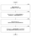
- 11 is a flowchart (2) illustrating an example of a station placement design process according to the present embodiment.
- FIG. 2 is a diagram illustrating an example of a hardware configuration of a station design apparatus according to the present embodiment.
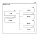
- ⁇ Configuration example of station design device> 1 is a diagram showing an example of the configuration of a station placement design device according to this embodiment.
- the station placement design device 100 is an information processing device having a computer configuration, or a system including multiple computers.
- the station placement design device 100 performs station placement design to design the installation position and orientation of an appropriate wireless base station or relay station (hereinafter referred to as "wireless base station, etc.") for constructing a wireless area, for example.
- wireless base station wireless base station, etc.
- the station design device 100 realizes the functional configuration of an input unit 101, a division unit 102, an estimation unit 103, a calculation unit 104, an output unit 105, etc., by, for example, a computer included in the station design device 100 executing a program stored in a storage medium.
- the station design device 100 also has a memory unit 111 realized by, for example, a storage device of the computer included in the station design device 100.
- the input unit 101 accepts various inputs to the station placement design device 100.
- the input unit 101 accepts input of design conditions for station placement design, and stores the accepted design conditions in the storage unit 111, etc.
- the design conditions for station design include, for example, information such as station location candidates, multiple evaluation points, required reception power (or required throughput), and the number of wireless base stations, etc. to be installed within the wireless area.
- the station location candidates are, for example, candidate installation locations for wireless base stations, etc., expressed as a combination of the installation location and orientation of the wireless base stations, etc.
- the orientation of the wireless base stations, etc. includes, for example, the orientation of the antennas equipped on the wireless base stations, etc., or the orientation in which the wireless base stations, etc. transmit and receive radio waves.
- the multiple evaluation points indicate the points within the wireless area where the reception power, etc. is evaluated.
- the required reception power (or required throughput) is, for example, a reference value (or target value) for determining whether sufficient reception power (or throughput) can be obtained at the evaluation point.
- the division unit 102 executes a division process that divides a plurality of evaluation points in a wireless area into a predetermined number of clusters based on the amount of radio wave propagation loss between the evaluation points.
- the division unit 102 divides the plurality of evaluation points into a predetermined number of clusters using the k-means++ method based on the radio wave spatial distance (the amount of radio wave propagation loss between the evaluation points).
- the division unit 102 divides the plurality of evaluation points in a wireless area into clusters equal in number to the number of wireless base stations, etc., installed in the wireless area. Note that a specific example of the process of dividing a plurality of evaluation points into a predetermined number of clusters will be described later.
- the estimation unit 103 executes an estimation process for estimating radio wave propagation from a station location candidate to an evaluation point within the cluster, for example, for each cluster divided by the division unit 102. For example, the estimation unit 103 calculates the received power at each evaluation point within the cluster for each station location candidate by simulating radio wave propagation characteristics such as ray tracing.
- the calculation unit 104 calculates a quality evaluation index for each station position candidate for each cluster based on the radio wave propagation estimation result by the estimation unit 103.
- the quality evaluation index include the average value of the received power at each evaluation point in the cluster, or the average value of the throughput predicted based on the received power at each evaluation point in the cluster.
- the calculation unit 104 may convert the received power to the throughput using a conversion table between received power and throughput prepared in advance. Alternatively, the calculation unit 104 may input the received power to a prediction model that has been machine-learned in advance to predict the throughput based on the received power, etc., to predict the throughput.
- the output unit 105 executes an output process to output, for each cluster, the installation position and orientation of the wireless base station, etc. (wireless base station or relay station) for which the quality evaluation index is the maximum, based on the quality evaluation index calculated by the calculation unit 104.
- the output unit 105 may output, for each cluster, the installation positions and orientations of a predetermined number of wireless base stations, etc., in descending order of the quality evaluation index, based on the quality evaluation index calculated by the calculation unit 104.
- the storage unit 111 stores various information, data, programs, etc., including, for example, the design conditions for the station placement design received by the input unit 101 and the estimation results of the radio wave propagation estimation calculated by the estimation unit 103.
- the functional configuration of the station placement design device 100 shown in FIG. 1 is an example.
- the memory unit 111 may be realized by a storage server that the station placement design device 100 can access via a communication network, or a class service.
- each of the above functional configurations is not limited to a physical machine (computer), and may be realized, for example, by a program executed by a virtual machine on the cloud.
- at least a part of each of the above functional configurations may be realized by hardware.
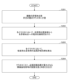
- (Channel placement design process 1) 2 is a flowchart showing an example of a station placement design process according to the present embodiment. This process shows an example of a station placement design process executed by the station placement design device 100 described with reference to FIG.
- step S201 the division unit 102 divides the multiple evaluation points in the wireless area into a predetermined number of clusters. For example, the division unit 102 performs clustering using the k-means++ method based on the radio wave spatial distance (the amount of radio wave propagation loss between the evaluation points).
- FIG. 3 is a diagram for explaining the station placement design process according to this embodiment.
- a plurality of shields 301, a plurality of evaluation points 302 where the received power from a wireless base station or the like is evaluated, and a plurality of station placement position candidates 303 are arranged in a wireless area 300.
- the plurality of evaluation points 302 are divided into three clusters 304a, 304b, and 304c.
- the division unit 102 divides the multiple evaluation points 302 in the wireless area 300 into clusters equal in number to the number of wireless base stations, etc. (wireless base stations or relay stations) to be installed in the wireless area 300. This makes it possible to place a predetermined number of wireless base stations, etc. in the wireless area 300, for example, by determining the optimal placement position and orientation of the wireless base stations, etc. for each cluster.
- the estimation unit 103 performs radio wave propagation estimation from each station location candidate 303 to each evaluation point 302 in each cluster. For example, as shown in FIG. 3, the estimation unit 103 calculates the received power from the station location candidate 303 to the evaluation point 302 in cluster 304a by radio wave propagation simulation such as ray tracing. In the same manner, the estimation unit 103 calculates the received power for all combinations of the station location candidate 303 and evaluation point 302 in cluster 304a. Furthermore, in the other clusters 304b and 304c, the estimation unit 103 calculates the received power for all combinations of the station location candidate 303 and evaluation point 302 in each cluster in the same manner.
- the estimation unit 103 may store the radio wave propagation estimation result calculated in step S202 in the storage unit 111 or the like, and reuse the result when executing the process of FIG. 2 again.
- the calculation unit 104 calculates a quality evaluation index for each station position candidate 303 in each cluster based on the estimation result of the radio wave propagation estimation.
- the quality evaluation index may be, for example, the average value of the received power received by each evaluation point 302 in the cluster from each station position candidate 303, or the average value of the throughput predicted based on the received power.
- the calculation unit 104 may predict the throughput from, for example, a conversion table between received power and throughput that is prepared in advance by acquiring actual measurement data or by link level simulation or the like. Alternatively, the calculation unit 104 may predict the throughput by inputting the received power into a prediction model that has been machine-learned in advance to predict throughput from the received power.
- the quality evaluation index may be, for example, the achievement rate of the target received power (or target throughput), or the minimum received power (or minimum throughput), etc.
- the station design device 100 can output the installation position and orientation of the wireless base station or the like that maximizes the quality evaluation index in each cluster.
- step S401 the output unit 105 outputs, for each cluster, the installation positions and orientations of a predetermined number of wireless base stations, etc., with the highest quality evaluation indexes, based on the quality evaluation index of each station position candidate 303.
- the output unit 105 outputs the installation positions and orientations of a predetermined number of wireless base stations, etc., in descending order of the quality evaluation index.
- the process of FIG. 4 makes it easy to determine the placement positions and orientations of wireless base stations, etc. so that the placement positions of wireless base stations, etc. are uniform, for example, when the placement positions of wireless base stations, etc. with the largest quality evaluation index are biased in each cluster.
- Cluster division process Here, an example of cluster division processing in which the division unit 102 divides a plurality of evaluation points 302 in the wireless area 300 into a predetermined number will be described.
- the division unit 102 divides the multiple evaluation points 302 into N clusters using the k-means++ method.
- k-means++ is a clustering method that divides given data into a specified number of clusters.
- a randomly selected evaluation point i is used as the initial value, the distance D between this point and the nearest neighbor center is calculated, and a weighted probability distribution (D ⁇ 2/ ⁇ D ⁇ 2) is used to randomly select evaluation point i+1, which will be the next cluster center.
- the division unit 102 repeats this process to select N cluster centers.
- the division unit 102 also generates clusters using the following (Equation 1) with the selected N cluster centers as initial values.
- Cj is a cluster and
- is the distance between the centroid (center of gravity of the cluster) and the cluster element.
- the amount of radio wave propagation loss (radio wave spatial distance) between the evaluation points 302 is used as the distance D between the evaluation points.
- the amount of radio wave loss between the evaluation points 302 is calculated by a radio wave propagation simulation or the like, taking into account the influence of multiple obstructions 301, as shown in FIG. 3, for example.
- the amount of radio wave loss between the evaluation points 302 may be actual measurement data or the like.
- the amount of radio wave loss between the evaluation points 302 may be calculated by the estimation unit 103, or may be a previously calculated or measured value stored in the storage unit 111 or the like.
- the amount of radio wave propagation loss between the centroid and the cluster elements in (Equation 1) may be calculated and obtained each time, or the centroid may be regarded as being the same as the evaluation point A of the nearest coordinates, and the amount of radio wave propagation loss between evaluation point A and another evaluation point 302 may be used.
- the k-means++ method is one example, and the division unit 102 may divide the multiple evaluation points 302 into N clusters using the amount of radio wave propagation loss between the evaluation points 302 and other clustering algorithms.
- the station placement design device 100 according to this embodiment is able to perform clustering calculations that take into account the obstruction 301. Therefore, the station placement design device 10 according to this embodiment is particularly suitable for station placement design in a system that uses a relatively high frequency band and in an environment where the influence of obstructions is significant, for example.
- FIG. 5 is a diagram showing an example of the hardware configuration of the station design device according to this embodiment.
- the station design device 100 has, for example, the hardware configuration of a computer 500 as shown in Fig. 5.
- the computer 500 has a processor 501, a memory 502, a storage device 503, a communication device 504, an input device 505, an output device 506, a bus B, etc.
- the processor 501 is, for example, an arithmetic device such as a CPU (Central Processing Unit) that realizes various functions by executing a specific program.
- the memory 502 is a storage medium readable by the computer 500, and includes, for example, a RAM (Random Access Memory) and a ROM (Read Only Memory).
- the storage device 503 is a computer-readable storage medium, and may include, for example, a HDD (Hard Disk Drive), an SSD (Solid State Drive), various optical disks, and magneto-optical disks.
- the communication device 504 includes one or more pieces of hardware (communication devices) for communicating with other devices via a wireless or wired network.
- the input device 505 is an input device (e.g., a keyboard, a mouse, a microphone, a switch, a button, a sensor, etc.) that accepts input from the outside.
- the output device 506 is an output device (e.g., a display, a speaker, an LED lamp, etc.) that outputs to the outside.
- the input device 505 and the output device 506 may be integrated into one configuration (e.g., an input/output device such as a touch panel display).
- Bus B is commonly connected to each of the above components and transmits, for example, address signals, data signals, and various control signals.
- the processor 501 is not limited to a CPU, and may be, for example, a DSP (Digital Signal Processor), a PLD (Programmable Logic Device), or an FPGA (Field Programmable Gate Array).
- the station design device 100 in this embodiment is not limited to being realized by a dedicated device, but may be realized by a general-purpose computer.
- a program for realizing this function may be recorded on a computer-readable recording medium, and the program recorded on the recording medium may be read into a computer system and executed to realize the function.
- the "computer system” here includes hardware such as an OS and peripheral devices.
- “computer-readable recording media” includes various storage devices such as portable media such as flexible disks, optical magnetic disks, ROMs, and CD-ROMs, as well as hard disks built into computer systems. Furthermore, “computer-readable recording media” may also include devices that dynamically hold a program for a short period of time, such as a communication line when transmitting a program via a network such as the Internet or a communication line such as a telephone line, and devices that hold a program for a certain period of time, such as volatile memory inside a computer system that serves as a server or client in such cases.
- the above program may be for realizing some of the functions described above, or may be capable of realizing the functions described above in combination with a program already recorded in the computer system, or may be realized using hardware such as a PLD (Programmable Logic Device) or FPGA (Field Programmable Gate Array).
- PLD Programmable Logic Device
- FPGA Field Programmable Gate Array
- the station design device 100 is capable of performing clustering calculations that take into account the obstructions 301, making it particularly suitable for network design in systems that use relatively high frequency bands and in environments where the obstructions 301 have a large impact.
- a station placement design device that designs an installation position and orientation of a radio base station or a relay station, a division unit that divides a plurality of evaluation points in a wireless area into a predetermined number of clusters based on an amount of radio wave propagation loss between the evaluation points; an estimation unit that performs radio wave propagation estimation from candidates for installation positions of the wireless base station or relay station, which are represented by a combination of the installation position and the orientation, to the evaluation point within the cluster, for each of the clusters; an output unit that outputs, based on a result of the radio wave propagation estimation, an installation position and an orientation of the radio base station or the relay station that maximizes a quality evaluation index at the evaluation point in the cluster; A station placement design device having the above-mentioned.
- (Section 2) 2. The station location design device according to claim 1, wherein the division unit divides the plurality of evaluation points in the wireless area into the predetermined number of clusters using a k-means++ algorithm with the amount of radio wave propagation loss between the evaluation points as the distance between the evaluation points. (Section 3) The division unit divides the plurality of evaluation points in the wireless area into clusters equal in number to the number of the wireless base stations or the relay stations installed in the wireless area, The output unit outputs, for each cluster, an installation position and an orientation of the wireless base station or the relay station that maximizes a quality evaluation index at the evaluation point in the cluster. 3. The station placement design device according to claim 1 or 2.
- a station location design device that designs an installation position and an orientation of a radio base station or a relay station, A process of dividing a plurality of evaluation points in a wireless area into a predetermined number of clusters based on an amount of radio wave propagation loss between the evaluation points; A process of performing radio wave propagation estimation to the evaluation point within the cluster from candidates for the installation positions of the wireless base station or relay station represented by a combination of the installation positions and orientations for each of the clusters; a process of outputting, based on a result of the radio wave propagation estimation, an installation position and an orientation of the wireless base station or the relay station that maximizes a quality evaluation index at the evaluation point in the cluster; A station placement design method that performs the above.
- (Section 7) A computer that designs the installation position and orientation of a wireless base station or a relay station, A process of dividing a plurality of evaluation points in a wireless area into a predetermined number of clusters based on an amount of radio wave propagation loss between the evaluation points; A process of performing radio wave propagation estimation to the evaluation point within the cluster from candidates for the installation positions of the wireless base station or relay station represented by a combination of the installation positions and orientations for each of the clusters; a process of outputting, based on a result of the radio wave propagation estimation, an installation position and an orientation of the wireless base station or the relay station that maximizes a quality evaluation index at the evaluation point in the cluster; A storage medium that stores a program that executes the program.
- REFERENCE SIGNS LIST 100 Station placement design device 102: Division unit 103: Estimation unit 104: Calculation unit 105: Output unit 111: Storage unit 500: Computer
Landscapes
- Engineering & Computer Science (AREA)
- Computer Networks & Wireless Communication (AREA)
- Signal Processing (AREA)
- Mobile Radio Communication Systems (AREA)
Abstract
Description
本発明は、置局設計装置、置局設計方法、及びプログラムに関する。 The present invention relates to a station placement design device, a station placement design method, and a program.
無線エリアを構築するための適切な無線基地局の設置位置等を設計する置局設計装置、及び置局設計方法が知られている。 A station placement design device and a station placement design method are known that design appropriate locations for wireless base stations to build wireless service areas.
従来の置局設計方法では、無線エリア内の複数の評価地点における無線通信品質のシミュレーション結果等から、例えば、所定の無線通信品質を満たす評価地点が最も多い等の条件により、無線基地局等(無線基地局又は中継局)の設置位置及び向きを選定する。 In conventional station placement design methods, the installation location and orientation of wireless base stations (wireless base stations or relay stations) are selected based on conditions such as the number of evaluation points that satisfy a specified wireless communication quality, for example, based on the results of simulating wireless communication quality at multiple evaluation points within a wireless area.
しかし、この方法では、無線基地局等の設置位置及び向きの候補が多くなると、無線基地局等の設置位置と向きの全ての組合せの計算結果を比較評価するために、必要な計算時間が膨大になるという問題がある。 However, this method has the problem that when there are many candidates for the installation positions and orientations of wireless base stations, etc., the calculation results of all combinations of the installation positions and orientations of wireless base stations, etc. must be compared and evaluated, resulting in a huge amount of calculation time.
本発明の実施形態は、上記の問題点に鑑みてなされたものであって、無線基地局等の設置位置及び向きを設計する置局設計装置において、設計に必要な計算時間を削減する。 The embodiment of the present invention was made in consideration of the above problems, and reduces the calculation time required for design in a station placement design device that designs the installation position and orientation of wireless base stations, etc.
上記の課題を解決するため、本発明の実施形態に係る置局設計装置は、無線基地局又は中継局の設置位置と向きとを設計する置局設計装置であって、無線エリア内の複数の評価地点を、前記評価地点の間の電波伝搬損失量に基づいて所定の数のクラスタに分割する分割部と、前記クラスタごとに、前記設置位置と向きとの組合せで表される前記無線基地局又は中継局の設置位置の候補から、前記クラスタ内の前記評価地点への電波伝搬推定を行う推定部と、前記電波伝搬推定の推定結果に基づいて、前記クラスタ内の前記評価地点における品質評価指標が最大となる前記無線基地局又は前記中継局の設置位置と向きとを出力する出力部と、を有する。 In order to solve the above problems, a station location design device according to an embodiment of the present invention is a station location design device that designs the installation position and orientation of a wireless base station or relay station, and includes a division unit that divides a plurality of evaluation points within a wireless area into a predetermined number of clusters based on the amount of radio wave propagation loss between the evaluation points, an estimation unit that performs radio wave propagation estimation from candidate installation positions of the wireless base station or relay station represented by a combination of the installation position and orientation for each cluster to the evaluation point within the cluster, and an output unit that outputs the installation position and orientation of the wireless base station or relay station that maximizes the quality evaluation index at the evaluation point within the cluster based on the estimation result of the radio wave propagation estimation.
本発明の実施形態によれば、無線基地局等の設置位置及び向きを設計する置局設計装置において、設計に必要な計算時間を削減することができる。 According to an embodiment of the present invention, it is possible to reduce the calculation time required for design in a station placement design device that designs the installation position and orientation of a wireless base station, etc.
以下、図面を参照して本発明の実施の形態(本実施形態)を説明する。以下で説明する実施形態は一例に過ぎず、本発明が適用される実施形態は、以下の実施形態に限られない。 Below, an embodiment of the present invention (the present embodiment) will be described with reference to the drawings. The embodiment described below is merely an example, and the embodiment to which the present invention is applicable is not limited to the following embodiment.
<置局設計装置の構成例>
図1は、本実施形態に係る置局設計装置の構成例を示す図である。置局設計装置100は、コンピュータの構成を有する情報処理装置、又は複数のコンピュータを含むシステムである。置局設計装置100は、例えば、無線エリアを構築するための適切な無線基地局又は中継局(以下、「無線基地局等」と呼ぶ)の設置位置と向きとを設計する置局設計を行う。
<Configuration example of station design device>
1 is a diagram showing an example of the configuration of a station placement design device according to this embodiment. The station
置局設計装置100は、例えば、置局設計装置100が備えるコンピュータが、記憶媒体に記憶したプログラムを実行することにより、入力部101、分割部102、推定部103、算出部104、及び出力部105等の機能構成を実現している。また置局設計装置100は、例えば、置局設計装置100が備えるコンピュータのストレージデバイス等によって実現される記憶部111を有している。
The
入力部101は、置局設計装置100に対する様々な入力を受け付ける。例えば、入力部101は、置局設計の設計条件の入力を受付し、受け付けた設計条件を記憶部111等に記憶する。
The
置局設計の設計条件には、例えば、置局位置候補、複数の評価地点、所要受信電力(又は所要スループット)、及び無線エリア内に設置する無線基地局等の数等の情報が含まれる。ここで、置局位置候補は、例えば、無線基地局等の設置位置と向きとの組合せで表される無線基地局等の設置位置の候補である。なお、無線基地局等の向きには、例えば、無線基地局等が備えるアンテナの向き、又は無線基地局等が電波を送受信する向き等が含まれる。複数の評価地点は、無線エリア内で受信電力等を評価する地点を示している。所要受信電力(又は所要スループット)は、評価地点で十分な受信電力(又はスループット)を得られるか等を判断するための基準値(又は目標値)等である。 The design conditions for station design include, for example, information such as station location candidates, multiple evaluation points, required reception power (or required throughput), and the number of wireless base stations, etc. to be installed within the wireless area. Here, the station location candidates are, for example, candidate installation locations for wireless base stations, etc., expressed as a combination of the installation location and orientation of the wireless base stations, etc. Note that the orientation of the wireless base stations, etc. includes, for example, the orientation of the antennas equipped on the wireless base stations, etc., or the orientation in which the wireless base stations, etc. transmit and receive radio waves. The multiple evaluation points indicate the points within the wireless area where the reception power, etc. is evaluated. The required reception power (or required throughput) is, for example, a reference value (or target value) for determining whether sufficient reception power (or throughput) can be obtained at the evaluation point.
分割部102は、無線エリア内の複数の評価地点を、評価地点の間の電波伝搬損失量に基づいて所定の数のクラスタに分割する分割処理を実行する。好ましくは、分割部102は、電波空間距離(評価地点の間の電波伝搬損失量)に基づいて、k-means++法により、複数の評価地点を所定の数のクラスタに分割する。好ましくは、分割部102は、無線エリア内の複数の評価地点を、無線エリア内に設置する無線基地局等の数のクラスタに分割する。なお、複数の評価地点を所定の数のクラスタに分割する処理の具体例については後述する。
The
推定部103は、例えば、分割部102が分割したクラスタごとに、置局位置候補から、クラスタ内の評価地点への電波伝搬推定を行う推定処理を実行する。例えば、推定部103は、レイトレース等の電波伝搬特性シミュレーションにより、置局位置候補ごとに、クラスタ内の各評価地点における受信電力を算出する。
The
算出部104は、推定部103による電波伝搬推定の推定結果に基づいて、クラスタごとに、各置局位置候補の品質評価指標を算出する。品質評価指標の例として、クラスタ内の各評価地点における受信電力の平均値、又はクラスタ内の各評価地点における受信電力に基づいて予測したスループットの平均値等がある。
The
なお、スループットの平均値を用いる場合、算出部104は、予め用意した受信電力とスループットとの換算表等を用いて受信電力をスループットに変換してもよい。或いは、算出部104は、受信電力等に基づいて、スループットを予測するように予め機械学習した予測モデルに、受信電力を入力して、スループットを予測してもよい。
When using the average throughput value, the
出力部105は、算出部104が算出した品質評価指標に基づいて、クラスタごとに、品質評価指標が最大となる無線基地局等(無線基地局又は中継局)の設置位置と向きとを出力する出力処理を実行する。別の一例として、出力部105は、算出部104が算出した品質評価指標に基づいて、クラスタごとに、品質評価指標が高い順に所定の数の無線基地局等の設置位置と向きとを出力してもよい。
The
記憶部111は、例えば、入力部101が受け付けた置局設計の設計条件、及び推定部103が算出した電波伝搬推定の推定結果等を含む様々な情報、データ、及びプログラム等を記憶する。
The
なお、図1に示した置局設計装置100の機能構成は一例である。例えば、記憶部111は、置局設計装置100が通信ネットワークを介してアクセス可能なストレージサーバ、又はクラスドサービス等によって実現されるものであってもよい。また、上記の各機能構成は、物理マシン(コンピュータ)に限られず、例えば、クラウド上の仮想マシン等が実行するプログラムにより実現されるものであっても良い。さらに、上記の各機能構成のうち、少なくとも一部は、ハードウェアによって実現されるものであってもよい。
The functional configuration of the station
<処理の流れ>
続いて、本実施形態に係る置局設計方法の処理の流れについて説明する。
<Processing flow>
Next, a process flow of the station placement design method according to this embodiment will be described.
(置局設計処理1)
図2は、本実施形態に係る置局設計処理の例を示すフローチャートである。この処理は、図1で説明した置局設計装置100が実行する置局設計処理の一例を示している。
(Channel placement design process 1)
2 is a flowchart showing an example of a station placement design process according to the present embodiment. This process shows an example of a station placement design process executed by the station
ステップS201において、分割部102は、無線エリア内の複数の評価地点を所定の数のクラスタに分割する。例えば、分割部102は、電波空間距離(評価地点の間の電波伝搬損失量)に基づくk-means++法によるクラスタリングを行う。
In step S201, the
図3は、本実施形態に係る置局設計処理について説明するための図である。図3の例では、無線エリア300に、複数の遮蔽物301、無線基地局等からの受信電力等を評価する地点である複数の評価地点302、及び複数の置局位置候補303が配置されている。また、図3の例では、一例として、複数の評価地点302を3つのクラスタ304a、304b、304cに分割した例を示している。
FIG. 3 is a diagram for explaining the station placement design process according to this embodiment. In the example of FIG. 3, a plurality of
好適な一例として、分割部102は、無線エリア300内の複数の評価地点302を、無線エリア300内に設置する無線基地局等(無線基地局又は中継局)の数のクラスタに分割する。これにより、例えば、クラスタごとに、最適な無線基地局等の配置位置と向きとを決定することにより、無線エリア300内に所定の数の無線基地局等を配置することができる。
As a preferred example, the
ステップS202において、推定部103は、各クラスタにおいて、各置局位置候補303から、各評価地点302への電波伝搬推定を行う。例えば、推定部103は、図3に示すように、クラスタ304aにおいて、置局位置候補303から評価地点302への受信電力を、レイトレース等の電波伝搬シミュレーションにより算出する。同様にして、推定部103は、クラスタ304a内の置局位置候補303と評価地点302の全ての組合せについて、受信電力を算出する。さらに、推定部103は、他のクラスタ304b、304cにおいても、同様にして、各クラスタ内の置局位置候補303と評価地点302の全ての組合せについて、受信電力を算出する。
In step S202, the
なお、推定部103は、ステップS202において算出した電波伝搬推定の推定結果を、記憶部111等に記憶しておき、図2の処理を再び実行するときに再利用してもよい。
The
ステップS203において、算出部104は、電波伝搬推定の推定結果に基づいて、各クラスタにおいて、各置局位置候補303の品質評価指標を算出する。ここで、品質評価指標には、例えば、各置局位置候補303から、クラスタ内の各評価地点302が受信する受信電力の平均値、又は受信電力に基づいて予測したスループットの平均値等がある。
In step S203, the
スループットを予測する場合、算出部104は、例えば、実測データの取得、又はリンクレベルシミュレーション等により予め用意した受信電力とスループットとの換算表から、スループットを予測してもよい。或いは、算出部104は、受信電力からスループットを予測するように予め機械学習した予測モデルに受信電力を入力して、スループットを予測してもよい。また、品質評価指標は、例えば、目標受信電力(又は目標スループット)の達成率、又は最低受信電力(又は最低スループット)等であってもよい。
When predicting throughput, the
ステップS204において、出力部105は、各置局位置候補303の品質評価指標に基づいて、クラスタごとに、品質評価指標が最大となる無線基地局等(無線基地局又は中継局)の設置位置と向きとを出力する。
In step S204, the
図3の処理により、置局設計装置100は、各クラスタにおいて、品質評価指標が最大となる無線基地局等の設置位置と向きとを出力することができる。
By performing the process shown in FIG. 3, the
(置局設計処理2)
図4は、本実施形態に係る置局設計処理の例を示すフローチャートである。この処理は、例えば、図1で説明した置局設計装置100が実行する置局設計処理の別の一例を示している。なお、図4の処理のうち、ステップS201~S203の処理は、図2で説明したステップS201~S203の処理と同様なので、ここでは説明を省略する。
(Channel placement design process 2)
Fig. 4 is a flowchart showing an example of the station placement design process according to this embodiment. This process shows another example of the station placement design process executed by the station
ステップS401において、出力部105は、各置局位置候補303の品質評価指標に基づいて、クラスタごとに、品質評価指標が上位の所定の数の無線基地局等の設置位置と向きとを出力する。好ましくは、出力部105は、品質評価指標が大きい順に、所定の数の無線基地局等の設置位置と向きとを出力する。
In step S401, the
図4の処理により、例えば、各クラスタにおいて、品質評価指標が最も大きい無線基地局等の設置位置が偏る場合、無線基地局等の配置位置が均等になるように、無線基地局等の配置位置と向きとを決定することが容易になる。 The process of FIG. 4 makes it easy to determine the placement positions and orientations of wireless base stations, etc. so that the placement positions of wireless base stations, etc. are uniform, for example, when the placement positions of wireless base stations, etc. with the largest quality evaluation index are biased in each cluster.
(クラスタの分割処理)
ここでは、分割部102が、無線エリア300内の複数の評価地点302を所定の数に分割するクラスタの分割処理の例について説明する。
(Cluster division process)
Here, an example of cluster division processing in which the
分割部102は、無線基地局等の数がN(Nは2以上の整数)である場合、複数の評価地点302を、k-means++法により、N個のクラスタに分割する。
When the number of wireless base stations, etc. is N (N is an integer equal to or greater than 2), the
k-means++は、与えられたデータを所定の数のクラスタに分けるクラスタリングの手法の1つである。 k-means++ is a clustering method that divides given data into a specified number of clusters.
k-means++では、ランダムに選択した評価点iを初期値として、その点との最近傍中心との距離Dを算出し、重み付き確率分布(D^2/ΣD^2)を用いて、ランダムに次のクラスタ中心となる評価点i+1を選択する。分割部102は、この処理を繰り返し実行して、N個のクラスタ中心を選択する。
In k-means++, a randomly selected evaluation point i is used as the initial value, the distance D between this point and the nearest neighbor center is calculated, and a weighted probability distribution (D^2/ΣD^2) is used to randomly select evaluation point i+1, which will be the next cluster center. The
また、分割部102は、選択したN個のクラスタ中心を初期値として、次の(式1)によりクラスタを生成する。
The

上述したk-means++法において、本実施形態では、評価点間の距離Dとして、評価地点302の間の電波伝搬損失量(電波空間距離)を用いる。この評価地点302間の電波損失量は、例えば、図3に示すように、複数の遮蔽物301影響を考慮して、電波伝搬シミュレーション等によって算出される。或いは、この評価地点302間の電波損失量は実測データ等であってもよい。また、この評価地点302間の電波損失量は、推定部103が算出してもよいし、予め算出、又は実測した値を記憶部111等に記憶しておくものであってもよい。
In the above k-means++ method, in this embodiment, the amount of radio wave propagation loss (radio wave spatial distance) between the evaluation points 302 is used as the distance D between the evaluation points. The amount of radio wave loss between the evaluation points 302 is calculated by a radio wave propagation simulation or the like, taking into account the influence of
なお、(式1)におけるセントロイドとクラスタ要素との間の電波伝搬損失量は、都度算出して取得してもよいし、セントロイドを最近傍の座標の評価地点Aと同一と見做して、評価地点Aと他の評価地点302との間の電波伝搬損失量を用いてもよい。
The amount of radio wave propagation loss between the centroid and the cluster elements in (Equation 1) may be calculated and obtained each time, or the centroid may be regarded as being the same as the evaluation point A of the nearest coordinates, and the amount of radio wave propagation loss between evaluation point A and another
ここで、k-means++法は一例であり、分割部102は、評価地点302間の電波伝搬損失量と、他のクラスタリングアルゴリズムとを用いて、複数の評価地点302をN個のクラスタに分割してもよい。
Here, the k-means++ method is one example, and the
これにより、本実施形態に係る置局設計装置100は、遮蔽物301を考慮したクラスタリング計算が可能になる。従って、本実施形態に係る置局設計装置10は、例えば、比較的高い周波数帯のシステム、かつ遮蔽物の影響が大きい環境における置局設計に特に適している。
As a result, the station
<ハードウェア構成例>
(置局設計装置のハードウェア構成)
図5は、本実施形態に係る置局設計装置のハードウェア構成の例を示す図である。置局設計装置100は、例えば、図5に示すようなコンピュータ500のハードウェア構成を有している。図5の例では、コンピュータ500は、プロセッサ501、メモリ502、ストレージデバイス503、通信装置504、入力装置505、出力装置506、及びバスB等を有する。
<Hardware configuration example>
(Hardware configuration of station design device)
Fig. 5 is a diagram showing an example of the hardware configuration of the station design device according to this embodiment. The
プロセッサ501は、例えば、所定のプログラムを実行することにより、様々な機能を実現するCPU(Central Processing Unit)等の演算装置である。メモリ502は、コンピュータ500が読み取り可能な記憶媒体であり、例えば、RAM(Random Access Memory)、ROM(Read Only Memory)等を含む。ストレージデバイス503は、コンピュータ読み取り可能な記憶媒体であり、例えば、HDD(Hard Disk Drive)、SSD(Solid State Drive)、各種の光ディスク、及び光磁気ディスク等を含み得る。
The
通信装置504は、無線、又は有線のネットワークを介して他の装置と通信を行うための1つ以上のハードウェア(通信デバイス)を含む。入力装置505は、外部からの入力を受け付ける入力デバイス(例えば、キーボード、マウス、マイクロフォン、スイッチ、ボタン、センサ等)である。出力装置506は、外部への出力を実施する出力デバイス(例えば、ディスプレイ、スピーカ、LEDランプ等)である。なお、入力装置505と出力装置506とは、一体となった構成(例えば、タッチパネルディスプレイ等の入出力装置)であってもよい。
The
バスBは、上記の各構成要素に共通に接続され、例えば、アドレス信号、データ信号、及び各種の制御信号等を伝送する。なお、プロセッサ501は、CPUに限られず、例えば、DSP(Digital Signal Processor)、PLD(Programmable Logic Device)、又はFPGA(Field Programmable Gate Array)等であってもよい。
Bus B is commonly connected to each of the above components and transmits, for example, address signals, data signals, and various control signals. Note that the
(補足)
本実施形態における置局設計装置100は専用装置による実現に限らず、汎用コンピュータで実現するようにしてもよい。その場合、この機能を実現するためのプログラムをコンピュータ読み取り可能な記録媒体に記録して、この記録媒体に記録されたプログラムをコンピュータシステムに読み込ませ、実行することによって実現してもよい。なお、ここでいう「コンピュータシステム」とは、OSや周辺機器等のハードウェアを含むものとする。
(supplement)
The
また、「コンピュータ読み取り可能な記録媒体」とは、フレキシブルディスク、光磁気ディスク、ROM、CD-ROM等の可搬媒体、コンピュータシステムに内蔵されるハードディスク等の様々な記憶装置を含む。さらに「コンピュータ読み取り可能な記録媒体」とは、インターネット等のネットワークや電話回線等の通信回線を介してプログラムを送信する場合の通信線のように、短時間の間、動的にプログラムを保持するもの、その場合のサーバやクライアントとなるコンピュータシステム内部の揮発性メモリのように、一定時間プログラムを保持しているものも含んでもよい。 In addition, "computer-readable recording media" includes various storage devices such as portable media such as flexible disks, optical magnetic disks, ROMs, and CD-ROMs, as well as hard disks built into computer systems. Furthermore, "computer-readable recording media" may also include devices that dynamically hold a program for a short period of time, such as a communication line when transmitting a program via a network such as the Internet or a communication line such as a telephone line, and devices that hold a program for a certain period of time, such as volatile memory inside a computer system that serves as a server or client in such cases.
また上記プログラムは、前述した機能の一部を実現するためのものであっても良く、さらに前述した機能をコンピュータシステムにすでに記録されているプログラムとの組み合わせで実現できるものであっても良く、PLD(Programmable Logic Device)やFPGA(Field Programmable Gate Array)等のハードウェアを用いて実現されるものであってもよい。 The above program may be for realizing some of the functions described above, or may be capable of realizing the functions described above in combination with a program already recorded in the computer system, or may be realized using hardware such as a PLD (Programmable Logic Device) or FPGA (Field Programmable Gate Array).
<実施形態の効果>
本実施形態によれば、無線基地局等の設置位置及び向きを設計する置局設計装置100において、設計に必要な計算時間を削減することができる。
Effects of the embodiment
According to this embodiment, in the station
また、置局設計装置100は、遮蔽物301を考慮したクラスタリング計算が可能なので、比較的高い周波数帯のシステム、かつ遮蔽物301の影響が大きい環境でのネットワーク設計に特に適する。
In addition, the
<実施形態のまとめ>
本明細書には、少なくとも下記各項の置局設計装置、置局設計方法、及びプログラムが開示されている。
(第1項)
無線基地局又は中継局の設置位置と向きとを設計する置局設計装置であって、
無線エリア内の複数の評価地点を、前記評価地点の間の電波伝搬損失量に基づいて所定の数のクラスタに分割する分割部と、
前記クラスタごとに、前記設置位置と向きとの組合せで表される前記無線基地局又は中継局の設置位置の候補から、前記クラスタ内の前記評価地点への電波伝搬推定を行う推定部と、
前記電波伝搬推定の推定結果に基づいて、前記クラスタ内の前記評価地点における品質評価指標が最大となる前記無線基地局又は前記中継局の設置位置と向きとを出力する出力部と、
を有する、置局設計装置。
(第2項)
前記分割部は、前記評価地点の間の電波伝搬損失量を、前記評価地点の間の距離としてk-means++法により、前記無線エリア内の前記複数の評価地点を、前記所定の数のクラスタに分割する、請求項1に記載の置局設計装置。
(第3項)
前記分割部は、前記無線エリア内の前記複数の評価地点を、前記無線エリア内に設置する前記無線基地局又は前記中継局の数のクラスタに分割し、
前記出力部は、前記クラスタごとに、前記クラスタ内の前記評価地点における品質評価指標が最大となる前記無線基地局又は前記中継局の設置位置と向きとを出力する、
第1項又は第2項に記載の置局設計装置。
(第4項)
前記品質評価指標は、前記電波伝搬推定により算出された前記評価地点における受信電力の平均値、又は前記受信電力に基づいて予測したスループットの平均値を含む、第1項~第3項のいずれかに記載の置局設計装置。
(第5項)
前記出力部は、前記クラスタ内の前記評価地点における品質評価指標が上位の所定の数の前記無線基地局又は前記中継局の設置位置と向きとを出力する、第1項~第4項のいずれかに記載の置局設計装置。
(第6項)
無線基地局又は中継局の設置位置と向きとを設計する置局設計装置が、
無線エリア内の複数の評価地点を、前記評価地点の間の電波伝搬損失量に基づいて所定の数のクラスタに分割する処理と、
前記クラスタごとに、前記設置位置と向きとの組合せで表される前記無線基地局又は中継局の設置位置の候補から、前記クラスタ内の前記評価地点への電波伝搬推定を行う処理と、
前記電波伝搬推定の推定結果に基づいて、前記クラスタ内の前記評価地点における品質評価指標が最大となる前記無線基地局又は前記中継局の設置位置と向きとを出力する処理と、
を実行する、置局設計方法。
(第7項)
無線基地局又は中継局の設置位置と向きとを設計するコンピュータに、
無線エリア内の複数の評価地点を、前記評価地点の間の電波伝搬損失量に基づいて所定の数のクラスタに分割する処理と、
前記クラスタごとに、前記設置位置と向きとの組合せで表される前記無線基地局又は中継局の設置位置の候補から、前記クラスタ内の前記評価地点への電波伝搬推定を行う処理と、
前記電波伝搬推定の推定結果に基づいて、前記クラスタ内の前記評価地点における品質評価指標が最大となる前記無線基地局又は前記中継局の設置位置と向きとを出力する処理と、
を実行させる、プログラムを記憶した記憶媒体。
Summary of the embodiment
This specification discloses at least the following station placement design apparatus, station placement design method, and program.
(Section 1)
A station placement design device that designs an installation position and orientation of a radio base station or a relay station,
a division unit that divides a plurality of evaluation points in a wireless area into a predetermined number of clusters based on an amount of radio wave propagation loss between the evaluation points;
an estimation unit that performs radio wave propagation estimation from candidates for installation positions of the wireless base station or relay station, which are represented by a combination of the installation position and the orientation, to the evaluation point within the cluster, for each of the clusters;
an output unit that outputs, based on a result of the radio wave propagation estimation, an installation position and an orientation of the radio base station or the relay station that maximizes a quality evaluation index at the evaluation point in the cluster;
A station placement design device having the above-mentioned.
(Section 2)
2. The station location design device according to claim 1, wherein the division unit divides the plurality of evaluation points in the wireless area into the predetermined number of clusters using a k-means++ algorithm with the amount of radio wave propagation loss between the evaluation points as the distance between the evaluation points.
(Section 3)
The division unit divides the plurality of evaluation points in the wireless area into clusters equal in number to the number of the wireless base stations or the relay stations installed in the wireless area,
The output unit outputs, for each cluster, an installation position and an orientation of the wireless base station or the relay station that maximizes a quality evaluation index at the evaluation point in the cluster.
3. The station placement design device according to claim 1 or 2.
(Section 4)
The station location design device according to any one of claims 1 to 3, wherein the quality evaluation index includes an average value of received power at the evaluation point calculated by the radio wave propagation estimation, or an average value of throughput predicted based on the received power.
(Section 5)
The station location design device according to any one of claims 1 to 4, wherein the output unit outputs the installation positions and orientations of a predetermined number of the radio base stations or the relay stations having top quality evaluation indexes at the evaluation points within the cluster.
(Section 6)
A station location design device that designs an installation position and an orientation of a radio base station or a relay station,
A process of dividing a plurality of evaluation points in a wireless area into a predetermined number of clusters based on an amount of radio wave propagation loss between the evaluation points;
A process of performing radio wave propagation estimation to the evaluation point within the cluster from candidates for the installation positions of the wireless base station or relay station represented by a combination of the installation positions and orientations for each of the clusters;
a process of outputting, based on a result of the radio wave propagation estimation, an installation position and an orientation of the wireless base station or the relay station that maximizes a quality evaluation index at the evaluation point in the cluster;
A station placement design method that performs the above.
(Section 7)
A computer that designs the installation position and orientation of a wireless base station or a relay station,
A process of dividing a plurality of evaluation points in a wireless area into a predetermined number of clusters based on an amount of radio wave propagation loss between the evaluation points;
A process of performing radio wave propagation estimation to the evaluation point within the cluster from candidates for the installation positions of the wireless base station or relay station represented by a combination of the installation positions and orientations for each of the clusters;
a process of outputting, based on a result of the radio wave propagation estimation, an installation position and an orientation of the wireless base station or the relay station that maximizes a quality evaluation index at the evaluation point in the cluster;
A storage medium that stores a program that executes the program.
以上、本実施形態について説明したが、本発明はかかる特定の実施形態に限定されるものではなく、特許請求の範囲に記載された本発明の要旨の範囲内において、種々の変形・変更が可能である。 Although the present embodiment has been described above, the present invention is not limited to this specific embodiment, and various modifications and variations are possible within the scope of the gist of the present invention as described in the claims.
100 置局設計装置
102 分割部
103 推定部
104 算出部
105 出力部
111 記憶部
500 コンピュータ
REFERENCE SIGNS LIST 100: Station placement design device 102: Division unit 103: Estimation unit 104: Calculation unit 105: Output unit 111: Storage unit 500: Computer
Claims (7)
無線エリア内の複数の評価地点を、前記評価地点の間の電波伝搬損失量に基づいて所定の数のクラスタに分割する分割部と、
前記クラスタごとに、前記設置位置と向きとの組合せで表される前記無線基地局又は中継局の設置位置の候補から、前記クラスタ内の前記評価地点への電波伝搬推定を行う推定部と、
前記電波伝搬推定の推定結果に基づいて、前記クラスタ内の前記評価地点における品質評価指標が最大となる前記無線基地局又は前記中継局の設置位置と向きとを出力する出力部と、
を有する、置局設計装置。 A station placement design device that designs an installation position and orientation of a radio base station or a relay station,
a division unit that divides a plurality of evaluation points in a wireless area into a predetermined number of clusters based on an amount of radio wave propagation loss between the evaluation points;
an estimation unit that performs radio wave propagation estimation from candidates for installation positions of the wireless base station or relay station, which are represented by a combination of the installation position and the orientation, to the evaluation point within the cluster, for each of the clusters;
an output unit that outputs, based on a result of the radio wave propagation estimation, an installation position and an orientation of the radio base station or the relay station that maximizes a quality evaluation index at the evaluation point in the cluster;
A station placement design device having the above-mentioned.
前記出力部は、前記クラスタごとに、前記クラスタ内の前記評価地点における品質評価指標が最大となる前記無線基地局又は前記中継局の設置位置と向きとを出力する、
請求項1又は2に記載の置局設計装置。 The division unit divides the plurality of evaluation points in the wireless area into clusters equal in number to the number of the wireless base stations or the relay stations installed in the wireless area,
The output unit outputs, for each cluster, an installation position and an orientation of the wireless base station or the relay station that maximizes a quality evaluation index at the evaluation point in the cluster.
The station placement design device according to claim 1 or 2.
無線エリア内の複数の評価地点を、前記評価地点の間の電波伝搬損失量に基づいて所定の数のクラスタに分割する処理と、
前記クラスタごとに、前記設置位置と向きとの組合せで表される前記無線基地局又は中継局の設置位置の候補から、前記クラスタ内の前記評価地点への電波伝搬推定を行う処理と、
前記電波伝搬推定の推定結果に基づいて、前記クラスタ内の前記評価地点における品質評価指標が最大となる前記無線基地局又は前記中継局の設置位置と向きとを出力する処理と、
を実行する、置局設計方法。 A station location design device that designs an installation position and an orientation of a radio base station or a relay station,
A process of dividing a plurality of evaluation points in a wireless area into a predetermined number of clusters based on an amount of radio wave propagation loss between the evaluation points;
A process of performing radio wave propagation estimation to the evaluation point within the cluster from candidates for the installation positions of the wireless base station or relay station represented by a combination of the installation positions and orientations for each of the clusters;
a process of outputting, based on a result of the radio wave propagation estimation, an installation position and an orientation of the wireless base station or the relay station that maximizes a quality evaluation index at the evaluation point in the cluster;
A station placement design method that performs the above.
無線エリア内の複数の評価地点を、前記評価地点の間の電波伝搬損失量に基づいて所定の数のクラスタに分割する処理と、
前記クラスタごとに、前記設置位置と向きとの組合せで表される前記無線基地局又は中継局の設置位置の候補から、前記クラスタ内の前記評価地点への電波伝搬推定を行う処理と、
前記電波伝搬推定の推定結果に基づいて、前記クラスタ内の前記評価地点における品質評価指標が最大となる前記無線基地局又は前記中継局の設置位置と向きとを出力する処理と、
を実行させる、プログラム。 A computer that designs the installation position and orientation of a wireless base station or a relay station,
A process of dividing a plurality of evaluation points in a wireless area into a predetermined number of clusters based on an amount of radio wave propagation loss between the evaluation points;
A process of performing radio wave propagation estimation to the evaluation point within the cluster from candidates for the installation positions of the wireless base station or relay station represented by a combination of the installation positions and orientations for each of the clusters;
a process of outputting, based on a result of the radio wave propagation estimation, an installation position and an orientation of the wireless base station or the relay station that maximizes a quality evaluation index at the evaluation point in the cluster;
A program to execute.
Priority Applications (2)
| Application Number | Priority Date | Filing Date | Title |
|---|---|---|---|
| JP2025525925A JPWO2024252684A1 (en) | 2023-06-09 | 2023-06-09 | |
| PCT/JP2023/021615 WO2024252684A1 (en) | 2023-06-09 | 2023-06-09 | Station placement design device, station placement design method, and program |
Applications Claiming Priority (1)
| Application Number | Priority Date | Filing Date | Title |
|---|---|---|---|
| PCT/JP2023/021615 WO2024252684A1 (en) | 2023-06-09 | 2023-06-09 | Station placement design device, station placement design method, and program |
Publications (1)
| Publication Number | Publication Date |
|---|---|
| WO2024252684A1 true WO2024252684A1 (en) | 2024-12-12 |
Family
ID=93795833
Family Applications (1)
| Application Number | Title | Priority Date | Filing Date |
|---|---|---|---|
| PCT/JP2023/021615 Ceased WO2024252684A1 (en) | 2023-06-09 | 2023-06-09 | Station placement design device, station placement design method, and program |
Country Status (2)
| Country | Link |
|---|---|
| JP (1) | JPWO2024252684A1 (en) |
| WO (1) | WO2024252684A1 (en) |
Citations (5)
| Publication number | Priority date | Publication date | Assignee | Title |
|---|---|---|---|---|
| JP2004201269A (en) * | 2002-10-23 | 2004-07-15 | Nec Corp | Method, device, and program for establishing and designing base station of mobile communication system |
| WO2020250366A1 (en) * | 2019-06-13 | 2020-12-17 | 日本電信電話株式会社 | Station installation assistance design device, station installation assistance design method, and program |
| WO2022172332A1 (en) * | 2021-02-09 | 2022-08-18 | 日本電信電話株式会社 | Base station placement supporting device, base station placement supporting method and program |
| WO2022219669A1 (en) * | 2021-04-12 | 2022-10-20 | 日本電信電話株式会社 | Station site design assisting device and station site design assisting method |
| WO2023032223A1 (en) * | 2021-09-06 | 2023-03-09 | 日本電信電話株式会社 | Station installation design supporting method and station installation design supporting apparatus |
-
2023
- 2023-06-09 WO PCT/JP2023/021615 patent/WO2024252684A1/en not_active Ceased
- 2023-06-09 JP JP2025525925A patent/JPWO2024252684A1/ja active Pending
Patent Citations (5)
| Publication number | Priority date | Publication date | Assignee | Title |
|---|---|---|---|---|
| JP2004201269A (en) * | 2002-10-23 | 2004-07-15 | Nec Corp | Method, device, and program for establishing and designing base station of mobile communication system |
| WO2020250366A1 (en) * | 2019-06-13 | 2020-12-17 | 日本電信電話株式会社 | Station installation assistance design device, station installation assistance design method, and program |
| WO2022172332A1 (en) * | 2021-02-09 | 2022-08-18 | 日本電信電話株式会社 | Base station placement supporting device, base station placement supporting method and program |
| WO2022219669A1 (en) * | 2021-04-12 | 2022-10-20 | 日本電信電話株式会社 | Station site design assisting device and station site design assisting method |
| WO2023032223A1 (en) * | 2021-09-06 | 2023-03-09 | 日本電信電話株式会社 | Station installation design supporting method and station installation design supporting apparatus |
Also Published As
| Publication number | Publication date |
|---|---|
| JPWO2024252684A1 (en) | 2024-12-12 |
Similar Documents
| Publication | Publication Date | Title |
|---|---|---|
| Wu et al. | Location estimation via support vector regression | |
| US6640089B1 (en) | System and method for adaptively predicting radio wave propagation | |
| US20220078630A1 (en) | Station placement designing method, station placement designing apparatus and program | |
| JP2019012875A (en) | Radio device installation position determination device, radio device installation position determination method, and radio device installation position determination program | |
| CN113169777B (en) | Beam Alignment | |
| JP7521621B2 (en) | Base station layout support device, base station layout support method and program | |
| US12375936B2 (en) | Network planning tool for forecasting in telecommunications networks | |
| US12022496B2 (en) | Systems and methods for dynamic selection of a physical uplink control channel format | |
| US20090167756A1 (en) | Method and apparatus for computation of wireless signal diffraction in a three-dimensional space | |
| JP7786542B2 (en) | Station placement design device, station placement design method, and program | |
| CN113055901B (en) | Terminal positioning method and device | |
| WO2024252684A1 (en) | Station placement design device, station placement design method, and program | |
| JP7823769B2 (en) | Station placement design device and program | |
| JP7747210B2 (en) | Station placement design device, station placement design method, and program | |
| US11812279B2 (en) | Wireless base station installation position calculation method and wireless base station installation position calculation system | |
| CN114268390A (en) | RSRP switching point determining method, device, medium and electronic equipment | |
| JP7747209B2 (en) | Station placement design device, station placement design method, and program | |
| JP7571803B2 (en) | COMMUNICATION SYSTEM, CONTROL SERVER DEVICE, BASE STATION ARRANGEMENT METHOD, AND PROGRAM | |
| WO2024236756A1 (en) | Station placement design device, station placement design method, and program | |
| WO2025120824A1 (en) | Station installation design system, station installation design device, station installation design method, and program | |
| WO2025126286A1 (en) | Station deployment design system, station deployment design device, station deployment design method, and program | |
| JP7412379B2 (en) | Feature data generation device, wireless usage prediction system, feature data generation method, and computer program | |
| JP2025029970A (en) | REFLECTION DIRECTION CONTROL DEVICE, REFLECTION DIRECTION CONTROL METHOD, AND PROGRAM | |
| WO2025126285A1 (en) | Station installation design system, station installation design device, station installation design method, and program | |
| WO2024100810A1 (en) | Station placement design apparatus and program |
Legal Events
| Date | Code | Title | Description |
|---|---|---|---|
| 121 | Ep: the epo has been informed by wipo that ep was designated in this application |
Ref document number: 23940780 Country of ref document: EP Kind code of ref document: A1 |
|
| ENP | Entry into the national phase |
Ref document number: 2025525925 Country of ref document: JP Kind code of ref document: A |
|
| WWE | Wipo information: entry into national phase |
Ref document number: 2025525925 Country of ref document: JP |
|
| NENP | Non-entry into the national phase |
Ref country code: DE |