WO2024252684A1 - Dispositif de conception de placement de station, procédé de conception de placement de station et programme - Google Patents
Dispositif de conception de placement de station, procédé de conception de placement de station et programme Download PDFInfo
- Publication number
- WO2024252684A1 WO2024252684A1 PCT/JP2023/021615 JP2023021615W WO2024252684A1 WO 2024252684 A1 WO2024252684 A1 WO 2024252684A1 JP 2023021615 W JP2023021615 W JP 2023021615W WO 2024252684 A1 WO2024252684 A1 WO 2024252684A1
- Authority
- WO
- WIPO (PCT)
- Prior art keywords
- station
- radio wave
- cluster
- wave propagation
- evaluation
- Prior art date
- Legal status (The legal status is an assumption and is not a legal conclusion. Google has not performed a legal analysis and makes no representation as to the accuracy of the status listed.)
- Ceased
Links
Images


Classifications
-
- H—ELECTRICITY
- H04—ELECTRIC COMMUNICATION TECHNIQUE
- H04W—WIRELESS COMMUNICATION NETWORKS
- H04W16/00—Network planning, e.g. coverage or traffic planning tools; Network deployment, e.g. resource partitioning or cells structures
- H04W16/18—Network planning tools
- H04W16/20—Network planning tools for indoor coverage or short range network deployment
Definitions
- the present invention relates to a station placement design device, a station placement design method, and a program.
- the installation location and orientation of wireless base stations are selected based on conditions such as the number of evaluation points that satisfy a specified wireless communication quality, for example, based on the results of simulating wireless communication quality at multiple evaluation points within a wireless area.
- this method has the problem that when there are many candidates for the installation positions and orientations of wireless base stations, etc., the calculation results of all combinations of the installation positions and orientations of wireless base stations, etc. must be compared and evaluated, resulting in a huge amount of calculation time.
- the embodiment of the present invention was made in consideration of the above problems, and reduces the calculation time required for design in a station placement design device that designs the installation position and orientation of wireless base stations, etc.
- FIG. 1 is a diagram illustrating an example of the configuration of a station design device according to an embodiment of the present invention.
- 1 is a flowchart (1) illustrating an example of a station placement design process according to the present embodiment.
- FIG. 11 is a diagram for explaining a station placement design process according to the embodiment.
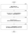
- 11 is a flowchart (2) illustrating an example of a station placement design process according to the present embodiment.
- FIG. 2 is a diagram illustrating an example of a hardware configuration of a station design apparatus according to the present embodiment.
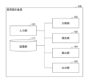
- ⁇ Configuration example of station design device> 1 is a diagram showing an example of the configuration of a station placement design device according to this embodiment.
- the station placement design device 100 is an information processing device having a computer configuration, or a system including multiple computers.
- the station placement design device 100 performs station placement design to design the installation position and orientation of an appropriate wireless base station or relay station (hereinafter referred to as "wireless base station, etc.") for constructing a wireless area, for example.
- wireless base station wireless base station, etc.
- the station design device 100 realizes the functional configuration of an input unit 101, a division unit 102, an estimation unit 103, a calculation unit 104, an output unit 105, etc., by, for example, a computer included in the station design device 100 executing a program stored in a storage medium.
- the station design device 100 also has a memory unit 111 realized by, for example, a storage device of the computer included in the station design device 100.
- the input unit 101 accepts various inputs to the station placement design device 100.
- the input unit 101 accepts input of design conditions for station placement design, and stores the accepted design conditions in the storage unit 111, etc.
- the design conditions for station design include, for example, information such as station location candidates, multiple evaluation points, required reception power (or required throughput), and the number of wireless base stations, etc. to be installed within the wireless area.
- the station location candidates are, for example, candidate installation locations for wireless base stations, etc., expressed as a combination of the installation location and orientation of the wireless base stations, etc.
- the orientation of the wireless base stations, etc. includes, for example, the orientation of the antennas equipped on the wireless base stations, etc., or the orientation in which the wireless base stations, etc. transmit and receive radio waves.
- the multiple evaluation points indicate the points within the wireless area where the reception power, etc. is evaluated.
- the required reception power (or required throughput) is, for example, a reference value (or target value) for determining whether sufficient reception power (or throughput) can be obtained at the evaluation point.
- the division unit 102 executes a division process that divides a plurality of evaluation points in a wireless area into a predetermined number of clusters based on the amount of radio wave propagation loss between the evaluation points.
- the division unit 102 divides the plurality of evaluation points into a predetermined number of clusters using the k-means++ method based on the radio wave spatial distance (the amount of radio wave propagation loss between the evaluation points).
- the division unit 102 divides the plurality of evaluation points in a wireless area into clusters equal in number to the number of wireless base stations, etc., installed in the wireless area. Note that a specific example of the process of dividing a plurality of evaluation points into a predetermined number of clusters will be described later.
- the estimation unit 103 executes an estimation process for estimating radio wave propagation from a station location candidate to an evaluation point within the cluster, for example, for each cluster divided by the division unit 102. For example, the estimation unit 103 calculates the received power at each evaluation point within the cluster for each station location candidate by simulating radio wave propagation characteristics such as ray tracing.
- the calculation unit 104 calculates a quality evaluation index for each station position candidate for each cluster based on the radio wave propagation estimation result by the estimation unit 103.
- the quality evaluation index include the average value of the received power at each evaluation point in the cluster, or the average value of the throughput predicted based on the received power at each evaluation point in the cluster.
- the calculation unit 104 may convert the received power to the throughput using a conversion table between received power and throughput prepared in advance. Alternatively, the calculation unit 104 may input the received power to a prediction model that has been machine-learned in advance to predict the throughput based on the received power, etc., to predict the throughput.
- the output unit 105 executes an output process to output, for each cluster, the installation position and orientation of the wireless base station, etc. (wireless base station or relay station) for which the quality evaluation index is the maximum, based on the quality evaluation index calculated by the calculation unit 104.
- the output unit 105 may output, for each cluster, the installation positions and orientations of a predetermined number of wireless base stations, etc., in descending order of the quality evaluation index, based on the quality evaluation index calculated by the calculation unit 104.
- the storage unit 111 stores various information, data, programs, etc., including, for example, the design conditions for the station placement design received by the input unit 101 and the estimation results of the radio wave propagation estimation calculated by the estimation unit 103.
- the functional configuration of the station placement design device 100 shown in FIG. 1 is an example.
- the memory unit 111 may be realized by a storage server that the station placement design device 100 can access via a communication network, or a class service.
- each of the above functional configurations is not limited to a physical machine (computer), and may be realized, for example, by a program executed by a virtual machine on the cloud.
- at least a part of each of the above functional configurations may be realized by hardware.
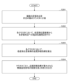
- (Channel placement design process 1) 2 is a flowchart showing an example of a station placement design process according to the present embodiment. This process shows an example of a station placement design process executed by the station placement design device 100 described with reference to FIG.
- step S201 the division unit 102 divides the multiple evaluation points in the wireless area into a predetermined number of clusters. For example, the division unit 102 performs clustering using the k-means++ method based on the radio wave spatial distance (the amount of radio wave propagation loss between the evaluation points).
- FIG. 3 is a diagram for explaining the station placement design process according to this embodiment.
- a plurality of shields 301, a plurality of evaluation points 302 where the received power from a wireless base station or the like is evaluated, and a plurality of station placement position candidates 303 are arranged in a wireless area 300.
- the plurality of evaluation points 302 are divided into three clusters 304a, 304b, and 304c.
- the division unit 102 divides the multiple evaluation points 302 in the wireless area 300 into clusters equal in number to the number of wireless base stations, etc. (wireless base stations or relay stations) to be installed in the wireless area 300. This makes it possible to place a predetermined number of wireless base stations, etc. in the wireless area 300, for example, by determining the optimal placement position and orientation of the wireless base stations, etc. for each cluster.
- the estimation unit 103 performs radio wave propagation estimation from each station location candidate 303 to each evaluation point 302 in each cluster. For example, as shown in FIG. 3, the estimation unit 103 calculates the received power from the station location candidate 303 to the evaluation point 302 in cluster 304a by radio wave propagation simulation such as ray tracing. In the same manner, the estimation unit 103 calculates the received power for all combinations of the station location candidate 303 and evaluation point 302 in cluster 304a. Furthermore, in the other clusters 304b and 304c, the estimation unit 103 calculates the received power for all combinations of the station location candidate 303 and evaluation point 302 in each cluster in the same manner.
- the estimation unit 103 may store the radio wave propagation estimation result calculated in step S202 in the storage unit 111 or the like, and reuse the result when executing the process of FIG. 2 again.
- the calculation unit 104 calculates a quality evaluation index for each station position candidate 303 in each cluster based on the estimation result of the radio wave propagation estimation.
- the quality evaluation index may be, for example, the average value of the received power received by each evaluation point 302 in the cluster from each station position candidate 303, or the average value of the throughput predicted based on the received power.
- the calculation unit 104 may predict the throughput from, for example, a conversion table between received power and throughput that is prepared in advance by acquiring actual measurement data or by link level simulation or the like. Alternatively, the calculation unit 104 may predict the throughput by inputting the received power into a prediction model that has been machine-learned in advance to predict throughput from the received power.
- the quality evaluation index may be, for example, the achievement rate of the target received power (or target throughput), or the minimum received power (or minimum throughput), etc.
- the station design device 100 can output the installation position and orientation of the wireless base station or the like that maximizes the quality evaluation index in each cluster.
- step S401 the output unit 105 outputs, for each cluster, the installation positions and orientations of a predetermined number of wireless base stations, etc., with the highest quality evaluation indexes, based on the quality evaluation index of each station position candidate 303.
- the output unit 105 outputs the installation positions and orientations of a predetermined number of wireless base stations, etc., in descending order of the quality evaluation index.
- the process of FIG. 4 makes it easy to determine the placement positions and orientations of wireless base stations, etc. so that the placement positions of wireless base stations, etc. are uniform, for example, when the placement positions of wireless base stations, etc. with the largest quality evaluation index are biased in each cluster.
- Cluster division process Here, an example of cluster division processing in which the division unit 102 divides a plurality of evaluation points 302 in the wireless area 300 into a predetermined number will be described.
- the division unit 102 divides the multiple evaluation points 302 into N clusters using the k-means++ method.
- k-means++ is a clustering method that divides given data into a specified number of clusters.
- a randomly selected evaluation point i is used as the initial value, the distance D between this point and the nearest neighbor center is calculated, and a weighted probability distribution (D ⁇ 2/ ⁇ D ⁇ 2) is used to randomly select evaluation point i+1, which will be the next cluster center.
- the division unit 102 repeats this process to select N cluster centers.
- the division unit 102 also generates clusters using the following (Equation 1) with the selected N cluster centers as initial values.
- Cj is a cluster and
- is the distance between the centroid (center of gravity of the cluster) and the cluster element.
- the amount of radio wave propagation loss (radio wave spatial distance) between the evaluation points 302 is used as the distance D between the evaluation points.
- the amount of radio wave loss between the evaluation points 302 is calculated by a radio wave propagation simulation or the like, taking into account the influence of multiple obstructions 301, as shown in FIG. 3, for example.
- the amount of radio wave loss between the evaluation points 302 may be actual measurement data or the like.
- the amount of radio wave loss between the evaluation points 302 may be calculated by the estimation unit 103, or may be a previously calculated or measured value stored in the storage unit 111 or the like.
- the amount of radio wave propagation loss between the centroid and the cluster elements in (Equation 1) may be calculated and obtained each time, or the centroid may be regarded as being the same as the evaluation point A of the nearest coordinates, and the amount of radio wave propagation loss between evaluation point A and another evaluation point 302 may be used.
- the k-means++ method is one example, and the division unit 102 may divide the multiple evaluation points 302 into N clusters using the amount of radio wave propagation loss between the evaluation points 302 and other clustering algorithms.
- the station placement design device 100 according to this embodiment is able to perform clustering calculations that take into account the obstruction 301. Therefore, the station placement design device 10 according to this embodiment is particularly suitable for station placement design in a system that uses a relatively high frequency band and in an environment where the influence of obstructions is significant, for example.
- FIG. 5 is a diagram showing an example of the hardware configuration of the station design device according to this embodiment.
- the station design device 100 has, for example, the hardware configuration of a computer 500 as shown in Fig. 5.
- the computer 500 has a processor 501, a memory 502, a storage device 503, a communication device 504, an input device 505, an output device 506, a bus B, etc.
- the processor 501 is, for example, an arithmetic device such as a CPU (Central Processing Unit) that realizes various functions by executing a specific program.
- the memory 502 is a storage medium readable by the computer 500, and includes, for example, a RAM (Random Access Memory) and a ROM (Read Only Memory).
- the storage device 503 is a computer-readable storage medium, and may include, for example, a HDD (Hard Disk Drive), an SSD (Solid State Drive), various optical disks, and magneto-optical disks.
- the communication device 504 includes one or more pieces of hardware (communication devices) for communicating with other devices via a wireless or wired network.
- the input device 505 is an input device (e.g., a keyboard, a mouse, a microphone, a switch, a button, a sensor, etc.) that accepts input from the outside.
- the output device 506 is an output device (e.g., a display, a speaker, an LED lamp, etc.) that outputs to the outside.
- the input device 505 and the output device 506 may be integrated into one configuration (e.g., an input/output device such as a touch panel display).
- Bus B is commonly connected to each of the above components and transmits, for example, address signals, data signals, and various control signals.
- the processor 501 is not limited to a CPU, and may be, for example, a DSP (Digital Signal Processor), a PLD (Programmable Logic Device), or an FPGA (Field Programmable Gate Array).
- the station design device 100 in this embodiment is not limited to being realized by a dedicated device, but may be realized by a general-purpose computer.
- a program for realizing this function may be recorded on a computer-readable recording medium, and the program recorded on the recording medium may be read into a computer system and executed to realize the function.
- the "computer system” here includes hardware such as an OS and peripheral devices.
- “computer-readable recording media” includes various storage devices such as portable media such as flexible disks, optical magnetic disks, ROMs, and CD-ROMs, as well as hard disks built into computer systems. Furthermore, “computer-readable recording media” may also include devices that dynamically hold a program for a short period of time, such as a communication line when transmitting a program via a network such as the Internet or a communication line such as a telephone line, and devices that hold a program for a certain period of time, such as volatile memory inside a computer system that serves as a server or client in such cases.
- the above program may be for realizing some of the functions described above, or may be capable of realizing the functions described above in combination with a program already recorded in the computer system, or may be realized using hardware such as a PLD (Programmable Logic Device) or FPGA (Field Programmable Gate Array).
- PLD Programmable Logic Device
- FPGA Field Programmable Gate Array
- the station design device 100 is capable of performing clustering calculations that take into account the obstructions 301, making it particularly suitable for network design in systems that use relatively high frequency bands and in environments where the obstructions 301 have a large impact.
- a station placement design device that designs an installation position and orientation of a radio base station or a relay station, a division unit that divides a plurality of evaluation points in a wireless area into a predetermined number of clusters based on an amount of radio wave propagation loss between the evaluation points; an estimation unit that performs radio wave propagation estimation from candidates for installation positions of the wireless base station or relay station, which are represented by a combination of the installation position and the orientation, to the evaluation point within the cluster, for each of the clusters; an output unit that outputs, based on a result of the radio wave propagation estimation, an installation position and an orientation of the radio base station or the relay station that maximizes a quality evaluation index at the evaluation point in the cluster; A station placement design device having the above-mentioned.
- (Section 2) 2. The station location design device according to claim 1, wherein the division unit divides the plurality of evaluation points in the wireless area into the predetermined number of clusters using a k-means++ algorithm with the amount of radio wave propagation loss between the evaluation points as the distance between the evaluation points. (Section 3) The division unit divides the plurality of evaluation points in the wireless area into clusters equal in number to the number of the wireless base stations or the relay stations installed in the wireless area, The output unit outputs, for each cluster, an installation position and an orientation of the wireless base station or the relay station that maximizes a quality evaluation index at the evaluation point in the cluster. 3. The station placement design device according to claim 1 or 2.
- a station location design device that designs an installation position and an orientation of a radio base station or a relay station, A process of dividing a plurality of evaluation points in a wireless area into a predetermined number of clusters based on an amount of radio wave propagation loss between the evaluation points; A process of performing radio wave propagation estimation to the evaluation point within the cluster from candidates for the installation positions of the wireless base station or relay station represented by a combination of the installation positions and orientations for each of the clusters; a process of outputting, based on a result of the radio wave propagation estimation, an installation position and an orientation of the wireless base station or the relay station that maximizes a quality evaluation index at the evaluation point in the cluster; A station placement design method that performs the above.
- (Section 7) A computer that designs the installation position and orientation of a wireless base station or a relay station, A process of dividing a plurality of evaluation points in a wireless area into a predetermined number of clusters based on an amount of radio wave propagation loss between the evaluation points; A process of performing radio wave propagation estimation to the evaluation point within the cluster from candidates for the installation positions of the wireless base station or relay station represented by a combination of the installation positions and orientations for each of the clusters; a process of outputting, based on a result of the radio wave propagation estimation, an installation position and an orientation of the wireless base station or the relay station that maximizes a quality evaluation index at the evaluation point in the cluster; A storage medium that stores a program that executes the program.
- REFERENCE SIGNS LIST 100 Station placement design device 102: Division unit 103: Estimation unit 104: Calculation unit 105: Output unit 111: Storage unit 500: Computer
Landscapes
- Engineering & Computer Science (AREA)
- Computer Networks & Wireless Communication (AREA)
- Signal Processing (AREA)
- Mobile Radio Communication Systems (AREA)
Abstract
Un dispositif de conception de placement de station conçoit une position d'installation et une orientation pour une station de base sans fil ou une station relais, le dispositif de conception de placement de station comprenant : une unité de division pour diviser une pluralité de points d'évaluation dans la zone sans fil en un nombre prédéterminé de grappes sur la base de la quantité d'affaiblissement de propagation d'ondes radio entre les points d'évaluation ; une unité d'estimation pour estimer, pour chacune des grappes, une propagation d'ondes radio vers les points d'évaluation dans la grappe depuis une position d'installation candidate pour la station de base sans fil ou la station relais, la position d'installation candidate étant représentée par une combinaison de la position d'installation et de l'orientation ; et une unité de sortie pour délivrer en sortie la position d'installation et l'orientation pour la station de base sans fil ou la station de relais qui obtient l'indice d'évaluation de qualité maximale au niveau des points d'évaluation dans la grappe, une telle sortie étant effectuée sur la base des résultats d'estimation de l'estimation de propagation d'onde radio.
Priority Applications (2)
| Application Number | Priority Date | Filing Date | Title |
|---|---|---|---|
| JP2025525925A JPWO2024252684A1 (fr) | 2023-06-09 | 2023-06-09 | |
| PCT/JP2023/021615 WO2024252684A1 (fr) | 2023-06-09 | 2023-06-09 | Dispositif de conception de placement de station, procédé de conception de placement de station et programme |
Applications Claiming Priority (1)
| Application Number | Priority Date | Filing Date | Title |
|---|---|---|---|
| PCT/JP2023/021615 WO2024252684A1 (fr) | 2023-06-09 | 2023-06-09 | Dispositif de conception de placement de station, procédé de conception de placement de station et programme |
Publications (1)
| Publication Number | Publication Date |
|---|---|
| WO2024252684A1 true WO2024252684A1 (fr) | 2024-12-12 |
Family
ID=93795833
Family Applications (1)
| Application Number | Title | Priority Date | Filing Date |
|---|---|---|---|
| PCT/JP2023/021615 Ceased WO2024252684A1 (fr) | 2023-06-09 | 2023-06-09 | Dispositif de conception de placement de station, procédé de conception de placement de station et programme |
Country Status (2)
| Country | Link |
|---|---|
| JP (1) | JPWO2024252684A1 (fr) |
| WO (1) | WO2024252684A1 (fr) |
Citations (5)
| Publication number | Priority date | Publication date | Assignee | Title |
|---|---|---|---|---|
| JP2004201269A (ja) * | 2002-10-23 | 2004-07-15 | Nec Corp | 移動通信システムにおける基地局設置設計方法及び基地局設置設計装置並びにプログラム |
| WO2020250366A1 (fr) * | 2019-06-13 | 2020-12-17 | 日本電信電話株式会社 | Dispositif ainsi que procédé de soutien à la conception pour installation de station, et programme |
| WO2022172332A1 (fr) * | 2021-02-09 | 2022-08-18 | 日本電信電話株式会社 | Dispositif de prise en charge de placement de station de base, procédé de prise en charge de placement de station de base et programme |
| WO2022219669A1 (fr) * | 2021-04-12 | 2022-10-20 | 日本電信電話株式会社 | Dispositif et procédé d'aide à la conception de site de station |
| WO2023032223A1 (fr) * | 2021-09-06 | 2023-03-09 | 日本電信電話株式会社 | Procédé de prise en charge de conception d'installation de station et appareil de prise en charge de conception d'installation de station |
-
2023
- 2023-06-09 WO PCT/JP2023/021615 patent/WO2024252684A1/fr not_active Ceased
- 2023-06-09 JP JP2025525925A patent/JPWO2024252684A1/ja active Pending
Patent Citations (5)
| Publication number | Priority date | Publication date | Assignee | Title |
|---|---|---|---|---|
| JP2004201269A (ja) * | 2002-10-23 | 2004-07-15 | Nec Corp | 移動通信システムにおける基地局設置設計方法及び基地局設置設計装置並びにプログラム |
| WO2020250366A1 (fr) * | 2019-06-13 | 2020-12-17 | 日本電信電話株式会社 | Dispositif ainsi que procédé de soutien à la conception pour installation de station, et programme |
| WO2022172332A1 (fr) * | 2021-02-09 | 2022-08-18 | 日本電信電話株式会社 | Dispositif de prise en charge de placement de station de base, procédé de prise en charge de placement de station de base et programme |
| WO2022219669A1 (fr) * | 2021-04-12 | 2022-10-20 | 日本電信電話株式会社 | Dispositif et procédé d'aide à la conception de site de station |
| WO2023032223A1 (fr) * | 2021-09-06 | 2023-03-09 | 日本電信電話株式会社 | Procédé de prise en charge de conception d'installation de station et appareil de prise en charge de conception d'installation de station |
Also Published As
| Publication number | Publication date |
|---|---|
| JPWO2024252684A1 (fr) | 2024-12-12 |
Similar Documents
| Publication | Publication Date | Title |
|---|---|---|
| Wu et al. | Location estimation via support vector regression | |
| US6640089B1 (en) | System and method for adaptively predicting radio wave propagation | |
| US20220078630A1 (en) | Station placement designing method, station placement designing apparatus and program | |
| JP2019012875A (ja) | 無線機器の設置位置決定装置、無線機器の設置位置決定方法及び無線機器の設置位置決定プログラム | |
| CN113169777B (zh) | 波束对准 | |
| JP7521621B2 (ja) | 基地局配置支援装置、基地局配置支援方法及びプログラム | |
| US12375936B2 (en) | Network planning tool for forecasting in telecommunications networks | |
| US12022496B2 (en) | Systems and methods for dynamic selection of a physical uplink control channel format | |
| US20090167756A1 (en) | Method and apparatus for computation of wireless signal diffraction in a three-dimensional space | |
| JP7786542B2 (ja) | 置局設計装置、置局設計方法、及びプログラム | |
| CN113055901B (zh) | 一种终端定位的方法和装置 | |
| WO2024252684A1 (fr) | Dispositif de conception de placement de station, procédé de conception de placement de station et programme | |
| JP7823769B2 (ja) | 置局設計装置、及びプログラム | |
| JP7747210B2 (ja) | 置局設計装置、置局設計方法、及びプログラム | |
| US11812279B2 (en) | Wireless base station installation position calculation method and wireless base station installation position calculation system | |
| CN114268390A (zh) | Rsrp切换点确定方法、装置、介质及电子设备 | |
| JP7747209B2 (ja) | 置局設計装置、置局設計方法、及びプログラム | |
| JP7571803B2 (ja) | 通信システム、制御サーバ装置、基地局配置方法、及びプログラム | |
| WO2024236756A1 (fr) | Dispositif de conception de placement de station, procédé de conception de placement de station et programme | |
| WO2025120824A1 (fr) | Système de conception d'installation de station, dispositif de conception d'installation de station, procédé de conception d'installation de station et programme | |
| WO2025126286A1 (fr) | Système de conception de déploiement de station, dispositif de conception de déploiement de station, procédé de conception de déploiement de station et programme | |
| JP7412379B2 (ja) | 特徴量データ生成装置、無線利用予測システム、特徴量データ生成方法及びコンピュータプログラム | |
| JP2025029970A (ja) | 反射方向制御装置、反射方向制御方法、及びプログラム | |
| WO2025126285A1 (fr) | Système de conception d'installation de station, dispositif de conception d'installation de station, procédé de conception d'installation de station et programme | |
| WO2024100810A1 (fr) | Appareil et programme de conception de placement de station |
Legal Events
| Date | Code | Title | Description |
|---|---|---|---|
| 121 | Ep: the epo has been informed by wipo that ep was designated in this application |
Ref document number: 23940780 Country of ref document: EP Kind code of ref document: A1 |
|
| ENP | Entry into the national phase |
Ref document number: 2025525925 Country of ref document: JP Kind code of ref document: A |
|
| WWE | Wipo information: entry into national phase |
Ref document number: 2025525925 Country of ref document: JP |
|
| NENP | Non-entry into the national phase |
Ref country code: DE |