WO2024252692A1 - 防振装置 - Google Patents
防振装置 Download PDFInfo
- Publication number
- WO2024252692A1 WO2024252692A1 PCT/JP2023/042377 JP2023042377W WO2024252692A1 WO 2024252692 A1 WO2024252692 A1 WO 2024252692A1 JP 2023042377 W JP2023042377 W JP 2023042377W WO 2024252692 A1 WO2024252692 A1 WO 2024252692A1
- Authority
- WO
- WIPO (PCT)
- Prior art keywords
- vibration
- elastic member
- stopper
- inner member
- elastic
- Prior art date
- Legal status (The legal status is an assumption and is not a legal conclusion. Google has not performed a legal analysis and makes no representation as to the accuracy of the status listed.)
- Ceased
Links
Images



Classifications
-
- F—MECHANICAL ENGINEERING; LIGHTING; HEATING; WEAPONS; BLASTING
- F16—ENGINEERING ELEMENTS AND UNITS; GENERAL MEASURES FOR PRODUCING AND MAINTAINING EFFECTIVE FUNCTIONING OF MACHINES OR INSTALLATIONS; THERMAL INSULATION IN GENERAL
- F16F—SPRINGS; SHOCK-ABSORBERS; MEANS FOR DAMPING VIBRATION
- F16F15/00—Suppression of vibrations in systems; Means or arrangements for avoiding or reducing out-of-balance forces, e.g. due to motion
- F16F15/02—Suppression of vibrations of non-rotating, e.g. reciprocating systems; Suppression of vibrations of rotating systems by use of members not moving with the rotating systems
- F16F15/04—Suppression of vibrations of non-rotating, e.g. reciprocating systems; Suppression of vibrations of rotating systems by use of members not moving with the rotating systems using elastic means
- F16F15/08—Suppression of vibrations of non-rotating, e.g. reciprocating systems; Suppression of vibrations of rotating systems by use of members not moving with the rotating systems using elastic means with rubber springs ; with springs made of rubber and metal
-
- F—MECHANICAL ENGINEERING; LIGHTING; HEATING; WEAPONS; BLASTING
- F16—ENGINEERING ELEMENTS AND UNITS; GENERAL MEASURES FOR PRODUCING AND MAINTAINING EFFECTIVE FUNCTIONING OF MACHINES OR INSTALLATIONS; THERMAL INSULATION IN GENERAL
- F16F—SPRINGS; SHOCK-ABSORBERS; MEANS FOR DAMPING VIBRATION
- F16F1/00—Springs
- F16F1/36—Springs made of rubber or other material having high internal friction, e.g. thermoplastic elastomers
- F16F1/371—Springs made of rubber or other material having high internal friction, e.g. thermoplastic elastomers characterised by inserts or auxiliary extension or exterior elements, e.g. for rigidification
-
- F—MECHANICAL ENGINEERING; LIGHTING; HEATING; WEAPONS; BLASTING
- F16—ENGINEERING ELEMENTS AND UNITS; GENERAL MEASURES FOR PRODUCING AND MAINTAINING EFFECTIVE FUNCTIONING OF MACHINES OR INSTALLATIONS; THERMAL INSULATION IN GENERAL
- F16F—SPRINGS; SHOCK-ABSORBERS; MEANS FOR DAMPING VIBRATION
- F16F1/00—Springs
- F16F1/36—Springs made of rubber or other material having high internal friction, e.g. thermoplastic elastomers
- F16F1/373—Springs made of rubber or other material having high internal friction, e.g. thermoplastic elastomers characterised by having a particular shape
-
- F—MECHANICAL ENGINEERING; LIGHTING; HEATING; WEAPONS; BLASTING
- F16—ENGINEERING ELEMENTS AND UNITS; GENERAL MEASURES FOR PRODUCING AND MAINTAINING EFFECTIVE FUNCTIONING OF MACHINES OR INSTALLATIONS; THERMAL INSULATION IN GENERAL
- F16F—SPRINGS; SHOCK-ABSORBERS; MEANS FOR DAMPING VIBRATION
- F16F1/00—Springs
- F16F1/36—Springs made of rubber or other material having high internal friction, e.g. thermoplastic elastomers
- F16F1/38—Springs made of rubber or other material having high internal friction, e.g. thermoplastic elastomers with a sleeve of elastic material between a rigid outer sleeve and a rigid inner sleeve or pin, i.e. bushing-type
- F16F1/3828—End stop features or buffering
-
- F—MECHANICAL ENGINEERING; LIGHTING; HEATING; WEAPONS; BLASTING
- F16—ENGINEERING ELEMENTS AND UNITS; GENERAL MEASURES FOR PRODUCING AND MAINTAINING EFFECTIVE FUNCTIONING OF MACHINES OR INSTALLATIONS; THERMAL INSULATION IN GENERAL
- F16F—SPRINGS; SHOCK-ABSORBERS; MEANS FOR DAMPING VIBRATION
- F16F1/00—Springs
- F16F1/36—Springs made of rubber or other material having high internal friction, e.g. thermoplastic elastomers
- F16F1/38—Springs made of rubber or other material having high internal friction, e.g. thermoplastic elastomers with a sleeve of elastic material between a rigid outer sleeve and a rigid inner sleeve or pin, i.e. bushing-type
- F16F1/3842—Method of assembly, production or treatment; Mounting thereof
- F16F1/3849—Mounting brackets therefor, e.g. stamped steel brackets; Restraining links
-
- F—MECHANICAL ENGINEERING; LIGHTING; HEATING; WEAPONS; BLASTING
- F16—ENGINEERING ELEMENTS AND UNITS; GENERAL MEASURES FOR PRODUCING AND MAINTAINING EFFECTIVE FUNCTIONING OF MACHINES OR INSTALLATIONS; THERMAL INSULATION IN GENERAL
- F16F—SPRINGS; SHOCK-ABSORBERS; MEANS FOR DAMPING VIBRATION
- F16F1/00—Springs
- F16F1/36—Springs made of rubber or other material having high internal friction, e.g. thermoplastic elastomers
- F16F1/38—Springs made of rubber or other material having high internal friction, e.g. thermoplastic elastomers with a sleeve of elastic material between a rigid outer sleeve and a rigid inner sleeve or pin, i.e. bushing-type
- F16F1/3863—Springs made of rubber or other material having high internal friction, e.g. thermoplastic elastomers with a sleeve of elastic material between a rigid outer sleeve and a rigid inner sleeve or pin, i.e. bushing-type characterised by the rigid sleeves or pin, e.g. of non-circular cross-section
-
- F—MECHANICAL ENGINEERING; LIGHTING; HEATING; WEAPONS; BLASTING
- F16—ENGINEERING ELEMENTS AND UNITS; GENERAL MEASURES FOR PRODUCING AND MAINTAINING EFFECTIVE FUNCTIONING OF MACHINES OR INSTALLATIONS; THERMAL INSULATION IN GENERAL
- F16F—SPRINGS; SHOCK-ABSORBERS; MEANS FOR DAMPING VIBRATION
- F16F13/00—Units comprising springs of the non-fluid type as well as vibration-dampers, shock-absorbers, or fluid springs
- F16F13/04—Units comprising springs of the non-fluid type as well as vibration-dampers, shock-absorbers, or fluid springs comprising both a plastics spring and a damper, e.g. a friction damper
- F16F13/06—Units comprising springs of the non-fluid type as well as vibration-dampers, shock-absorbers, or fluid springs comprising both a plastics spring and a damper, e.g. a friction damper the damper being a fluid damper, e.g. the plastics spring not forming a part of the wall of the fluid chamber of the damper
- F16F13/08—Units comprising springs of the non-fluid type as well as vibration-dampers, shock-absorbers, or fluid springs comprising both a plastics spring and a damper, e.g. a friction damper the damper being a fluid damper, e.g. the plastics spring not forming a part of the wall of the fluid chamber of the damper the plastics spring forming at least a part of the wall of the fluid chamber of the damper
- F16F13/10—Units comprising springs of the non-fluid type as well as vibration-dampers, shock-absorbers, or fluid springs comprising both a plastics spring and a damper, e.g. a friction damper the damper being a fluid damper, e.g. the plastics spring not forming a part of the wall of the fluid chamber of the damper the plastics spring forming at least a part of the wall of the fluid chamber of the damper the wall being at least in part formed by a flexible membrane or the like
-
- F—MECHANICAL ENGINEERING; LIGHTING; HEATING; WEAPONS; BLASTING
- F16—ENGINEERING ELEMENTS AND UNITS; GENERAL MEASURES FOR PRODUCING AND MAINTAINING EFFECTIVE FUNCTIONING OF MACHINES OR INSTALLATIONS; THERMAL INSULATION IN GENERAL
- F16F—SPRINGS; SHOCK-ABSORBERS; MEANS FOR DAMPING VIBRATION
- F16F13/00—Units comprising springs of the non-fluid type as well as vibration-dampers, shock-absorbers, or fluid springs
- F16F13/04—Units comprising springs of the non-fluid type as well as vibration-dampers, shock-absorbers, or fluid springs comprising both a plastics spring and a damper, e.g. a friction damper
- F16F13/06—Units comprising springs of the non-fluid type as well as vibration-dampers, shock-absorbers, or fluid springs comprising both a plastics spring and a damper, e.g. a friction damper the damper being a fluid damper, e.g. the plastics spring not forming a part of the wall of the fluid chamber of the damper
- F16F13/08—Units comprising springs of the non-fluid type as well as vibration-dampers, shock-absorbers, or fluid springs comprising both a plastics spring and a damper, e.g. a friction damper the damper being a fluid damper, e.g. the plastics spring not forming a part of the wall of the fluid chamber of the damper the plastics spring forming at least a part of the wall of the fluid chamber of the damper
- F16F13/10—Units comprising springs of the non-fluid type as well as vibration-dampers, shock-absorbers, or fluid springs comprising both a plastics spring and a damper, e.g. a friction damper the damper being a fluid damper, e.g. the plastics spring not forming a part of the wall of the fluid chamber of the damper the plastics spring forming at least a part of the wall of the fluid chamber of the damper the wall being at least in part formed by a flexible membrane or the like
- F16F13/101—Units comprising springs of the non-fluid type as well as vibration-dampers, shock-absorbers, or fluid springs comprising both a plastics spring and a damper, e.g. a friction damper the damper being a fluid damper, e.g. the plastics spring not forming a part of the wall of the fluid chamber of the damper the plastics spring forming at least a part of the wall of the fluid chamber of the damper the wall being at least in part formed by a flexible membrane or the like characterised by buffering features or stoppers
-
- F—MECHANICAL ENGINEERING; LIGHTING; HEATING; WEAPONS; BLASTING
- F16—ENGINEERING ELEMENTS AND UNITS; GENERAL MEASURES FOR PRODUCING AND MAINTAINING EFFECTIVE FUNCTIONING OF MACHINES OR INSTALLATIONS; THERMAL INSULATION IN GENERAL
- F16F—SPRINGS; SHOCK-ABSORBERS; MEANS FOR DAMPING VIBRATION
- F16F2226/00—Manufacturing; Treatments
- F16F2226/04—Assembly or fixing methods; methods to form or fashion parts
- F16F2226/041—Clipping
-
- F—MECHANICAL ENGINEERING; LIGHTING; HEATING; WEAPONS; BLASTING
- F16—ENGINEERING ELEMENTS AND UNITS; GENERAL MEASURES FOR PRODUCING AND MAINTAINING EFFECTIVE FUNCTIONING OF MACHINES OR INSTALLATIONS; THERMAL INSULATION IN GENERAL
- F16F—SPRINGS; SHOCK-ABSORBERS; MEANS FOR DAMPING VIBRATION
- F16F2230/00—Purpose; Design features
- F16F2230/0041—Locking; Fixing in position
-
- F—MECHANICAL ENGINEERING; LIGHTING; HEATING; WEAPONS; BLASTING
- F16—ENGINEERING ELEMENTS AND UNITS; GENERAL MEASURES FOR PRODUCING AND MAINTAINING EFFECTIVE FUNCTIONING OF MACHINES OR INSTALLATIONS; THERMAL INSULATION IN GENERAL
- F16F—SPRINGS; SHOCK-ABSORBERS; MEANS FOR DAMPING VIBRATION
- F16F2230/00—Purpose; Design features
- F16F2230/0052—Physically guiding or influencing
- F16F2230/007—Physically guiding or influencing with, or used as an end stop or buffer; Limiting excessive axial separation
Definitions
- the present invention relates to an anti-vibration device.
- This application claims priority to Japanese Patent Application No. 2023-94375, filed on June 7, 2023, the entire contents of which are incorporated herein by reference.
- a conventional vibration isolation device includes an outer member (bracket) connected to one of the vibration generating side and the vibration receiving side, a first mounting member connected to the outer member, an inner member (second mounting member) connected to the other of the vibration generating side and the vibration receiving side and disposed inside the bracket, and an elastic member (elastic body) that connects the outer member and the inner member (see, for example, Patent Document 1).
- the inner member is provided with a stopper portion (press-fitted cylindrical portion) formed integrally with the elastic member, and the stopper portion is further disposed inside the bracket. The stopper portion can limit the relative movement between the outer member and the inner member by contacting the outer member.
- the stopper portion is formed integrally with the elastic member. Therefore, the spring constant of the stopper portion is lower than the spring constant of the second mounting member. Therefore, the conventional vibration-damping device can achieve soft spring characteristics when in contact with the bracket.
- the stopper portion is supported by the second mounting member. Therefore, in reality, the spring constant of the stopper portion increases immediately after it comes into contact with the bracket. That is, in the conventional vibration-damping device, the actual spring characteristics become stiff immediately after it comes into contact with the bracket. Therefore, if the conventional vibration-damping device is used as an engine mount, for example, there is a risk that it may affect the ride comfort.
- the object of the present invention is to provide an anti-vibration device that can reliably regulate excessive displacement between the outer member and the inner member while suppressing the increase in the spring constant after hitting the stopper.
- the vibration-damping device is an anti-vibration device comprising an outer member connected to one of the vibration generating side and the vibration receiving side, an inner member connected to the other of the vibration generating side and the vibration receiving side, and an elastic member that connects the outer member and the inner member and is disposed inside the outer member, and further comprising a stopper that contacts the outer member to limit relative movement between the outer member and the inner member, and the stopper is supported by the elastic member.
- the vibration-damping device can reliably regulate excessive displacement between the outer member and the inner member while suppressing an increase in the spring constant after contacting the stopper.
- the inner member has an annular portion in which a through-hole is formed, and the stopper can be supported by an elastic member including the elastic member disposed in the through-hole.
- the stopper can be supported by the elastic member with a simple configuration.
- the elastic member includes a connection portion that connects the outer member and the inner member so that they are aligned in a direction in which the same axis extends, and legs that support the inner member relative to the outer member, and the elastic member can further cover the annular portion of the inner member so as to surround the connection portion of the elastic member. In this case, it is effective in suppressing an increase in the spring constant after hitting the stopper.
- the present invention provides an anti-vibration device that can reliably regulate excessive displacement between the outer and inner members while suppressing an increase in the spring constant after hitting the stopper.
- FIG. 1 is a perspective view showing a vibration isolation device according to an exemplary embodiment of the present invention, viewed from the outer side in a vehicle width direction.
- 2 is a side view showing the vibration isolation device of FIG. 1 from the outer side in the vehicle width direction.
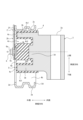
- FIG. 3 is a cross-sectional view showing the vibration isolation device of FIG. 2 along the line AA.
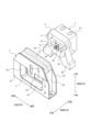
- 2 is an exploded view showing the vibration isolation device of FIG. 1 , divided into an outer member and an inner member provided with an elastic member.
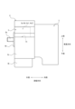
- FIG. 5 is a side view showing the inner member provided with the elastic member shown in FIG. 4, viewed from the outer side in the vehicle width direction.
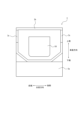
- FIG. FIG. 6 is a rear view showing the inner member shown in FIG.
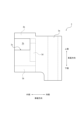
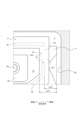
- FIG. 3 is a diagram partially and diagrammatically illustrating the internal structure of the vibration isolation device of FIG. 2.
- the vibration isolation device 1 can be attached to a vehicle.
- the vibration isolation device 1 is interposed between the vibration generating side and the vibration receiving side, thereby elastically connecting the vibration generating side and the vibration receiving side.
- the vibration isolation device 1 is an engine mount that connects the engine and the vehicle body. That is, in this embodiment, one of the vibration generating side and the vibration receiving side is one of the engine and the vehicle body, and the other of the vibration generating side and the vibration receiving side is the other of the engine and the vehicle body.
- the vibration isolation device 1 does not have to be an engine mount.
- the vibration isolation device 1 may be a vibration isolation device other than an engine mount.
- the vibration isolation device 1 may be a vibration isolation device for a vehicle other than an engine mount.
- the vibration isolation device 1 may be a vibration isolation device for a vehicle that includes an engine mount.
- all length direction refers to the front-to-rear direction (length direction) of the vehicle, and here refers to the direction when the vibration isolation device 1 is attached to the vehicle.
- vehicle width direction refers to the width direction of the vehicle, and here refers to the direction when the vibration isolation device 1 is attached to the vehicle.
- vehicle height direction refers to the height direction of the vehicle, and here refers to the direction when the vibration isolation device 1 is attached to the vehicle.
- the direction in which the axis O extends is also referred to as the "axial direction”.
- a view from the "axial direction” is also referred to as an "axial direction view”.
- a direction perpendicular to the axial direction is also referred to as the "axial-perpendicular direction”.
- a view from the "axial-perpendicular direction” is also referred to as an "axial-perpendicular direction view”.
- the vibration isolation device 1 includes an outer member 2 connected to one of the vibration generating side and the vibration receiving side, an inner member 3 connected to the other of the vibration generating side and the vibration receiving side, and an elastic member 4 that connects the outer member 2 and the inner member 3 and is disposed inside the outer member 2.
- the outer member 2 is fixed to the vehicle body on the vibration receiving side. This allows the vibration isolation device 1 to be supported by the vehicle body.
- the inner member 3 is fixed to the engine on the vibration generating side. This allows the vibration isolation device 1 to elastically support the engine relative to the vehicle body.
- the vibration isolation device 1 is provided with a stopper 5 that contacts the outer member 2 to limit the relative movement between the outer member 2 and the inner member 3.
- the stopper 5 is supported by an elastic member 4.
- the inner member 3 has an annular portion 3b in which a through portion 3c is formed.
- the support portion 5a of the stopper 5 is an elastic member 4 including the elastic member 4 arranged in the through portion 3c.
- the stopper 5 is supported by the elastic member 4 that penetrates the through portion 3c in the full length direction.
- the stopper 5 is supported by the support portion 5a made of the elastic member 4 having elasticity, which will be described later. As a result, in this embodiment, the stopper 5 is supported by the elastic member 4.
- the vibration isolation device 1 is shown diagrammatically in the A-A cross section of FIG. 2.
- the elastic member 4 has a connection portion 4a that connects the outer member 2 and the inner member 3 so that they are aligned in a line in the direction in which the same axis O extends, and legs 4b that support the inner member 3 relative to the outer member 2.
- the elastic member 4 covers the annular portion 3b of the inner member 3 so as to surround the connection portion 4a.
- the vibration isolation device 1 is described in more detail below.
- an accommodation space S for accommodating the elastic member 4 is formed inside the outer member 2.
- the outer member 2 includes a lower wall 2a fixed to the vehicle body, two full-length walls 2b standing from the lower wall 2a and spaced apart in the full-length direction, and an upper wall 2c connected to the upper ends of the two full-length walls 2b.
- the outer member 2 includes two vehicle width walls 2d spaced apart in the vehicle width direction.
- An opening A2 is formed in each of the two vehicle width walls 2d.
- the outer member 2 includes a connecting plate 2f. In this embodiment, the connecting plate 2f is attached to the vehicle width wall 2d on the outer side in the vehicle width direction of the two vehicle width walls 2d.
- the connecting plate 2f closes the upper portion of the opening A2 formed in the vehicle width wall 2d.
- the connecting plate 2f includes a long hole 2h extending in the vehicle height direction.
- the storage space S is defined by the above configuration.
- the outer member 2 is formed as a single unit.
- the inner member 3 has a mounting portion 3a.
- the engine is attached to the mounting portion 3a.
- An elastic member 4 is integrally formed on the outer side of the inner member 3 in the vehicle width direction.
- the inner member 3 has an annular portion 3b.
- the annular portion 3b extends from the mounting portion 3a to one side in the vehicle width direction (in this embodiment, the outer side in the vehicle width direction).
- the inner member 3 further has a raised portion 3d on the inside of the annular portion 3b.
- the raised portion 3d also extends from the mounting portion 3a to one side in the vehicle width direction (in this embodiment, the outer side in the vehicle width direction).
- the raised portion 3d functions as a base on which the connection portion 4a of the elastic member 4 is placed.
- the through portion 3c is a notch formed in the annular portion 3b. As shown in FIG. 8, in this embodiment, the through portion 3c extends from one side end of the annular portion 3b in the vehicle width direction (in this embodiment, the outer end of the annular portion 3b in the vehicle width direction) to the other side in the vehicle width direction (in this embodiment, the inner side of the annular portion 3b in the vehicle width direction). As shown in FIG. 8, in this embodiment, the through portion 3c is formed to coincide with one side end of the raised portion 3d in the vehicle width direction (in this embodiment, the outer end of the raised portion 3d in the vehicle width direction).
- the through portion 3c can be formed up to a position on the other side in the vehicle width direction (inner side in the vehicle width direction) of the one side end of the raised portion 3d in the vehicle width direction (outer end of the raised portion 3d in the vehicle width direction in this embodiment). Furthermore, the through portion 3c can be formed up to a position on one side in the vehicle width direction (outer side in the vehicle width direction) of the one side end of the raised portion 3d in the vehicle width direction (outer end of the raised portion 3d in the vehicle width direction in this embodiment).
- the outer member 2 and the inner member 3 are each made of a highly rigid material.
- highly rigid materials include metals and resins such as engineering plastics.
- the elastic member 4 includes a covering portion 4c that covers the annular portion 3b of the inner member 3.
- the connection portion 4a and the leg portion 4b are integrally formed via the covering portion 4c.
- the covering portion 4c includes an outer layer 4c1 that covers the outer peripheral surface of the annular portion 3b of the inner member 3, and an inner layer 4c2 that covers the inner peripheral surface of the annular portion 3b of the inner member 3.
- the elastic member 4 is pressed into the storage space S of the outer member 2.
- the elastic member 4 is attached to the outer member 2 by pressing the covering portion 4c and the leg portion 4b between the lower wall 2a and the upper wall 2c of the outer member 2.
- the upper surface of the outer layer 4c1 arranged on the upper side of the elastic member 4 is a flat surface, but the upper surface can be formed with unevenness, etc.
- connection portion 4a of the elastic member 4 is connected to the outer member 2 by a coupling portion 6.
- the coupling portion 6 is composed of a screw shaft 6a, a base plate 6b, and a nut 6c.
- a base plate 6b having a screw shaft 6a is attached to one end of the connection part 4a of the elastic member 4 in the vehicle width direction (in this embodiment, the outer end of the connection part 4a in the vehicle width direction).
- the screw shaft 6a passes through a long hole 2h formed in the connection plate 2f of the outer member 2, and is fixed to the connection plate 2f by a nut 6c. This allows the connection part 4a of the elastic member 4 to move up and down along the long hole 2h.
- the long hole 2h may be a perfect circle hole as long as it is a hole through which the screw shaft 6a can pass.
- the elastic member 4 has two legs 4b. Also, in this embodiment, the elastic member 4 has a recess 4n formed on one side in the vehicle width direction (in this embodiment, the outer side in the vehicle width direction). In this embodiment, the recess 4n is formed by the inner circumferential surface of the inner layer 4c2 of the covering portion 4c, with the annular portion 3b of the inner member 3 as a skeleton. In this embodiment, the through portion 3c formed in the annular portion 3b is filled with the elastic member 4. As a result, the support portion 5a of the stopper 5 is formed in the through portion 3c of the inner member 3 so as to penetrate the through portion 3c.
- the support portion 5a of the stopper 5 includes a base 4d made of the elastic member 4 present in the area partitioned by the through portion 3c of the inner member 3, and each of the outer layer 4c1 and the inner layer 4c2 of the covering portion 4c connected to the base 4d. That is, in this embodiment, the stopper 5 is composed of a base 4d disposed in the through-hole 3c formed in the inner member 3, an outer layer 4c1 of the covering portion 4c that covers the inner member 3, and an inner layer 4c2 of the covering portion 4c.
- the support portion 5a of the stopper 5 includes the inner layer 4c2 of the elastic member 4 in addition to the outer layer 4c1 and base 4d of the elastic member 4, as shown in FIG. 3. That is, in this embodiment, the thickness of the support portion 5a of the stopper 5 (in this embodiment, the thickness in the overall length direction) is the overall thickness of the elastic member 4 penetrating the penetrating portion 3c formed in the annular portion 3b of the inner member 3 (in this embodiment, the thickness in the overall length direction). However, the thickness of the support portion 5a of the stopper 5 can be changed as appropriate.
- the inner layer 4c2 does not exist in the elastic member 4, it can be the thickness of the outer layer 4c1 and base 4d of the elastic member 4 (in this embodiment, the thickness in the overall length direction).
- the support portion 5a of the stopper 5 can also be composed of only the base 4d of the elastic member 4.
- the stopper 5 is formed integrally with the elastic member 4.
- the stopper 5 is formed as part of the elastic member 4, that is, in this embodiment, the stopper 5 is formed from the same elastic material as the elastic member 4.
- the elastic material is a material that has a lower rigidity than the outer member 2 and the inner member 3 and has elasticity to absorb vibrations, such as rubber or elastomer.
- the elastic member 4 is formed from rubber.
- the elastic member 4 has two stoppers 5.
- the two stoppers 5 are formed on the front and rear sides of the covering portion 4c in the overall length direction, respectively.
- the stoppers 5 are arranged in a position aligned with the through-hole 3c formed in the annular portion 3b of the inner member 3 in the overall length direction, as shown in FIG. 5.
- the elastic member 4 has a recess 4n formed inside the covering portion 4c of the elastic member 4, which has the annular portion 3b of the inner member 3 as a skeleton, as shown in FIG. 5, when viewed in the axial direction. In this embodiment, no other member is present in the recess 4n surrounding the connection portion 4a.
- the stopper 5 is supported by the base 4d made of the elastic member 4 present in the area partitioned by the through-hole 3c of the inner member 3, and the outer layer 4c1 and inner layer 4c2 of the elastic member 4 connected to the base 4d, i.e., only by the elastic member 4.
- the stopper 5 is formed over the entire vehicle width direction of the covering portion 4c of the elastic member 4 so as to include the through portion 3c formed in the inner member 3.
- the stopper 5 is supported only by the base 4d of the elastic member 4 and the outer layer 4c1 and inner layer 4c2 of the elastic member 4 connected to the base 4d, i.e., by the elastic member 4.
- the through portion 3c of the inner member 3 is formed so as to be included in the stopper 5, but it can also be formed so as to coincide with the stopper 5.
- the through portion 3c of the inner member 3 can be formed so as to include the stopper 5.
- the stopper 5 contacts the full-length wall 2b of the outer member 2, thereby restricting the relative displacement between the outer member 2 and the inner member 3 in the full-length direction.
- the stopper 5 is supported by the annular portion 3b of the inner member 3, which has high rigidity, via the elastic member 4. Therefore, when the stopper 5 is disposed at the position of the annular portion 3b of the inner member 3, the restriction range of the stopper 5 is the range of the dimension ⁇ L0 between the rear end of the stopper 5 in the full length direction and the rear end of the annular portion 3b in the full length direction. In this case, the stopper 5 is suddenly compressed together with the elastic member 4 immediately after contacting the full length wall 2b of the outer member 2.
- the spring constant of the stopper 5 increases rapidly with respect to the spring constant originally possessed by the elastic member 4 immediately after contacting the full length wall 2b. That is, when the stopper 5 is disposed at the position of the annular portion 3b of the inner member 3 as in the conventional vibration-proof device, the actual spring characteristic changes in a direction that becomes suddenly harder immediately after contacting the outer member 2. Therefore, if the above conventional vibration-proof device is adopted as, for example, an engine mount, there is a risk of affecting the ride comfort.
- the stopper 5 is supported only by the elastic member 4. Therefore, in the case of the vibration-proof device 1, the regulated range of the stopper 5 is theoretically a range equal to or greater than the dimension ⁇ L1 between the rear end of the stopper 5 in the full-length direction and the inner circumferential surface of the recess 4n of the elastic member 4. In this case, the stopper 5 is not suddenly compressed together with the elastic member 4 immediately after contacting the full-length wall 2b of the outer member 2. Therefore, even after contacting the full-length wall 2b, the spring constant of the stopper 5 does not suddenly increase relative to the spring constant originally possessed by the elastic member 4.
- the vibration-proof device 1 in the case of the vibration-proof device 1, the actual spring characteristics are unlikely to suddenly change in the direction of hardening even after contacting the outer member 2. Therefore, when the vibration-proof device 1 is adopted as, for example, an engine mount, it is possible to suppress the influence on the ride comfort that may occur due to the spring characteristics suddenly changing in the direction of hardening.
- the thickness ( ⁇ L0) of the elastic member 4 used to restrict displacement is the same as when the through-hole 3c is not formed in the inner member 3. Therefore, in the case of the vibration-proof device 1 of this embodiment, there is no impact on durability, etc. compared to the conventional case.
- the stopper 5 is supported by the elastic member 4. Therefore, in the vibration isolation device 1 of this embodiment, for example, a separate rigid member (inner bracket) for connecting to the vibration generating side or vibration receiving side is inserted into the annular portion 3b of the inner member 3, and the inner member 3 is connected to the vibration generating side or vibration receiving side, and thus the stopper 5 is supported by the rigid member rather than the elastic member.
- the increase in the spring constant after the stopper hits can be suppressed while reliably restricting excessive displacement between the outer member 2 and the inner member 3, compared to when the stopper 5 is not supported by the elastic member 4. This ensures the reliability of the stopper 5 and improves the ride comfort performance after the stopper hits.
- the stopper 5 is supported by the elastic member 4 disposed in the through-hole 3c formed in the annular portion 3b of the inner member 3.
- the stopper 5 can be supported only by the elastic member 4 with a simple configuration in which the through-hole 3c is formed in the annular portion 3b of the inner member 3 and the base 4d of the elastic member 4 passing through the through-hole 3c is connected to the stopper 5.
- the through-hole 3c is a notch in this embodiment, it can also be a through hole.
- the elastic member 4 has a connection portion 4a that connects the outer member 2 and the inner member 3 so that they are aligned in a row in the direction in which the same axis O extends, and a leg portion 4b that supports the inner member 3 relative to the outer member 2. Furthermore, the elastic member 4 covers the annular portion 3b of the inner member 3 so as to surround the connection portion 4a.
- the outer member 2 and the inner member 3 can be elastically connected with a simple configuration that is completely different from the vibration-proof device using the connection member, without using a separate connection member.
- the base portion 4d of the elastic member 4 is adjacent to the recess 4n, and the part that comes into contact due to relative displacement between the outer member 2 and the inner member 3 is the connection portion 4a of the elastic member 4. Therefore, in this case, it is effective in suppressing the increase in the spring constant after hitting the stopper.
- the inner peripheral surface of the annular portion 3b of the inner member 3 is covered by the inner layer 4c2 of the elastic member 4.
- the base 4d of the elastic member 4 that supports the stopper 5 is connected to the inner layer 4c2 of the covering portion 4c.
- the base 4d of the elastic member 4 is firmly fixed to the through portion 3c formed in the annular portion 3b of the inner member 3. Therefore, in this case, the durability of the vibration isolation device 1 can be increased.
- the vibration isolation device 1 has been described as being mounted so that the axis O is parallel to the vehicle width direction, but it can also be mounted so that the axis O is parallel to the vehicle length direction or vehicle height direction. Furthermore, the axis O can also be mounted so that it intersects with the vehicle width direction, length direction, or vehicle height direction.
- the outer member 2 is connected to the vibration receiving side, but it may also be connected to the vibration generating side.
- the inner member 3 connected to the vibration generating side in this embodiment is connected to the vibration receiving side.
Landscapes
- Engineering & Computer Science (AREA)
- General Engineering & Computer Science (AREA)
- Mechanical Engineering (AREA)
- Manufacturing & Machinery (AREA)
- Chemical & Material Sciences (AREA)
- Combustion & Propulsion (AREA)
- Physics & Mathematics (AREA)
- Acoustics & Sound (AREA)
- Aviation & Aerospace Engineering (AREA)
- Vibration Prevention Devices (AREA)
- Springs (AREA)
Abstract
Description
Claims (4)
- 振動発生側及び振動受け側の一方に接続される外側部材と、前記振動発生側及び前記振動受け側の他方に接続される内側部材と、前記外側部材と前記内側部材とを連結するとともに前記外側部材の内部に配置される弾性部材とを備える、防振装置であって、
前記外側部材に接触することによって前記外側部材と前記内側部材との間の相対移動を制限するストッパを備えており、前記ストッパは、前記弾性部材によって支持されている、防振装置。 - 前記内側部材は、貫通部が形成された環状部を有しており、
前記ストッパは、前記貫通部に配置される前記弾性部材を含んだ当該弾性部材によって支持されている、請求項1に記載された防振装置。 - 前記弾性部材は、前記外側部材と前記内側部材とを、同一の軸線が延在する方向において一列に整列するように接続する接続部と、前記内側部材を前記外側部材に対して支持する脚部と、を備えており、
さらに、前記弾性部材は、前記弾性部材の前記接続部を取り囲むように前記内側部材の前記環状部を被覆している、請求項2に記載された防振装置。 - 前記内側部材の前記環状部の内周面は、前記弾性部材によって被覆されている、請求項2に記載された防振装置。
Priority Applications (3)
| Application Number | Priority Date | Filing Date | Title |
|---|---|---|---|
| CN202380097793.0A CN121039415A (zh) | 2023-06-07 | 2023-11-27 | 防振装置 |
| EP23940787.7A EP4726232A1 (en) | 2023-06-07 | 2023-11-27 | Vibration-proofing device |
| JP2025525930A JPWO2024252692A1 (ja) | 2023-06-07 | 2023-11-27 |
Applications Claiming Priority (2)
| Application Number | Priority Date | Filing Date | Title |
|---|---|---|---|
| JP2023094375 | 2023-06-07 | ||
| JP2023-094375 | 2023-06-07 |
Publications (1)
| Publication Number | Publication Date |
|---|---|
| WO2024252692A1 true WO2024252692A1 (ja) | 2024-12-12 |
Family
ID=93795202
Family Applications (1)
| Application Number | Title | Priority Date | Filing Date |
|---|---|---|---|
| PCT/JP2023/042377 Ceased WO2024252692A1 (ja) | 2023-06-07 | 2023-11-27 | 防振装置 |
Country Status (4)
| Country | Link |
|---|---|
| EP (1) | EP4726232A1 (ja) |
| JP (1) | JPWO2024252692A1 (ja) |
| CN (1) | CN121039415A (ja) |
| WO (1) | WO2024252692A1 (ja) |
Citations (6)
| Publication number | Priority date | Publication date | Assignee | Title |
|---|---|---|---|---|
| JP2006170447A (ja) * | 2004-12-16 | 2006-06-29 | Carl Freudenberg Kg | ユニットマウント |
| JP2014031843A (ja) * | 2012-08-03 | 2014-02-20 | Bridgestone Corp | 防振装置 |
| JP2016075322A (ja) * | 2014-10-03 | 2016-05-12 | 株式会社ブリヂストン | 防振装置 |
| WO2017056959A1 (ja) * | 2015-09-29 | 2017-04-06 | 住友理工株式会社 | 防振装置とその製造方法 |
| JP2017096331A (ja) | 2015-11-19 | 2017-06-01 | 株式会社ブリヂストン | 防振装置 |
| JP2023094375A (ja) | 2021-12-23 | 2023-07-05 | ダイムラー トラック エージー | 吸気ダクト |
-
2023
- 2023-11-27 JP JP2025525930A patent/JPWO2024252692A1/ja active Pending
- 2023-11-27 WO PCT/JP2023/042377 patent/WO2024252692A1/ja not_active Ceased
- 2023-11-27 CN CN202380097793.0A patent/CN121039415A/zh active Pending
- 2023-11-27 EP EP23940787.7A patent/EP4726232A1/en active Pending
Patent Citations (6)
| Publication number | Priority date | Publication date | Assignee | Title |
|---|---|---|---|---|
| JP2006170447A (ja) * | 2004-12-16 | 2006-06-29 | Carl Freudenberg Kg | ユニットマウント |
| JP2014031843A (ja) * | 2012-08-03 | 2014-02-20 | Bridgestone Corp | 防振装置 |
| JP2016075322A (ja) * | 2014-10-03 | 2016-05-12 | 株式会社ブリヂストン | 防振装置 |
| WO2017056959A1 (ja) * | 2015-09-29 | 2017-04-06 | 住友理工株式会社 | 防振装置とその製造方法 |
| JP2017096331A (ja) | 2015-11-19 | 2017-06-01 | 株式会社ブリヂストン | 防振装置 |
| JP2023094375A (ja) | 2021-12-23 | 2023-07-05 | ダイムラー トラック エージー | 吸気ダクト |
Non-Patent Citations (1)
| Title |
|---|
| See also references of EP4726232A1 |
Also Published As
| Publication number | Publication date |
|---|---|
| JPWO2024252692A1 (ja) | 2024-12-12 |
| CN121039415A (zh) | 2025-11-28 |
| EP4726232A1 (en) | 2026-04-15 |
Similar Documents
| Publication | Publication Date | Title |
|---|---|---|
| CN109424680B (zh) | 防振构造 | |
| WO2019187368A1 (ja) | 筒形防振装置 | |
| JP7219150B2 (ja) | 防振装置取付構造 | |
| JP6783162B2 (ja) | ブラケット付き防振装置 | |
| JP2017096321A (ja) | ブラケット付き防振装置 | |
| WO2024252692A1 (ja) | 防振装置 | |
| JP2010060022A (ja) | 防振ブッシュ | |
| CN112922988B (zh) | 带托架的筒型防振装置 | |
| JP4833883B2 (ja) | 防振装置 | |
| CN115135531A (zh) | 车辆用座椅 | |
| JP7527258B2 (ja) | 複数種類のブラケット付き筒型防振装置 | |
| JPH1026162A (ja) | 防振支持体 | |
| JP7121719B2 (ja) | ブラケット付き筒型防振装置 | |
| JP7460512B2 (ja) | 防振装置 | |
| JP5693386B2 (ja) | 防振装置 | |
| JP4757133B2 (ja) | トルクロッド | |
| JP7102234B2 (ja) | 防振装置 | |
| JP2018100727A (ja) | 防振装置 | |
| JP6182077B2 (ja) | 筒形防振装置 | |
| US20260016066A1 (en) | Tubular vibration-damping device for motor mount | |
| JPH06109050A (ja) | エンジンマウント | |
| JP5396252B2 (ja) | 筒形防振装置 | |
| JP4053037B2 (ja) | 液封入式防振装置 | |
| KR100460929B1 (ko) | 차량용 변속기의 마운팅 장치 | |
| JP2010091042A (ja) | 防振装置 |
Legal Events
| Date | Code | Title | Description |
|---|---|---|---|
| 121 | Ep: the epo has been informed by wipo that ep was designated in this application |
Ref document number: 23940787 Country of ref document: EP Kind code of ref document: A1 |
|
| ENP | Entry into the national phase |
Ref document number: 2025525930 Country of ref document: JP Kind code of ref document: A |
|
| WWE | Wipo information: entry into national phase |
Ref document number: 2025525930 Country of ref document: JP |
|
| WWE | Wipo information: entry into national phase |
Ref document number: CN2023800977930 Country of ref document: CN |
|
| WWE | Wipo information: entry into national phase |
Ref document number: 2023940787 Country of ref document: EP |
|
| NENP | Non-entry into the national phase |
Ref country code: DE |
|
| ENP | Entry into the national phase |
Ref document number: 2023940787 Country of ref document: EP Effective date: 20260107 |
|
| ENP | Entry into the national phase |
Ref document number: 2023940787 Country of ref document: EP Effective date: 20260107 |
|
| ENP | Entry into the national phase |
Ref document number: 2023940787 Country of ref document: EP Effective date: 20260107 |
|
| ENP | Entry into the national phase |
Ref document number: 2023940787 Country of ref document: EP Effective date: 20260107 |
|
| ENP | Entry into the national phase |
Ref document number: 2023940787 Country of ref document: EP Effective date: 20260107 |
|
| WWP | Wipo information: published in national office |
Ref document number: 2023940787 Country of ref document: EP |