WO2024252717A1 - Vehicle control device and vehicle control method - Google Patents
Vehicle control device and vehicle control method Download PDFInfo
- Publication number
- WO2024252717A1 WO2024252717A1 PCT/JP2024/001239 JP2024001239W WO2024252717A1 WO 2024252717 A1 WO2024252717 A1 WO 2024252717A1 JP 2024001239 W JP2024001239 W JP 2024001239W WO 2024252717 A1 WO2024252717 A1 WO 2024252717A1
- Authority
- WO
- WIPO (PCT)
- Prior art keywords
- vehicle
- target
- angular velocity
- control device
- vehicle body
- Prior art date
- Legal status (The legal status is an assumption and is not a legal conclusion. Google has not performed a legal analysis and makes no representation as to the accuracy of the status listed.)
- Ceased
Links
Images





Classifications
-
- B—PERFORMING OPERATIONS; TRANSPORTING
- B62—LAND VEHICLES FOR TRAVELLING OTHERWISE THAN ON RAILS
- B62D—MOTOR VEHICLES; TRAILERS
- B62D6/00—Arrangements for automatically controlling steering depending on driving conditions sensed and responded to, e.g. control circuits
- B62D6/002—Arrangements for automatically controlling steering depending on driving conditions sensed and responded to, e.g. control circuits computing target steering angles for front or rear wheels
- B62D6/003—Arrangements for automatically controlling steering depending on driving conditions sensed and responded to, e.g. control circuits computing target steering angles for front or rear wheels in order to control vehicle yaw movement, i.e. around a vertical axis
-
- B—PERFORMING OPERATIONS; TRANSPORTING
- B60—VEHICLES IN GENERAL
- B60W—CONJOINT CONTROL OF VEHICLE SUB-UNITS OF DIFFERENT TYPE OR DIFFERENT FUNCTION; CONTROL SYSTEMS SPECIALLY ADAPTED FOR HYBRID VEHICLES; ROAD VEHICLE DRIVE CONTROL SYSTEMS FOR PURPOSES NOT RELATED TO THE CONTROL OF A PARTICULAR SUB-UNIT
- B60W10/00—Conjoint control of vehicle sub-units of different type or different function
- B60W10/04—Conjoint control of vehicle sub-units of different type or different function including control of propulsion units
-
- B—PERFORMING OPERATIONS; TRANSPORTING
- B60—VEHICLES IN GENERAL
- B60W—CONJOINT CONTROL OF VEHICLE SUB-UNITS OF DIFFERENT TYPE OR DIFFERENT FUNCTION; CONTROL SYSTEMS SPECIALLY ADAPTED FOR HYBRID VEHICLES; ROAD VEHICLE DRIVE CONTROL SYSTEMS FOR PURPOSES NOT RELATED TO THE CONTROL OF A PARTICULAR SUB-UNIT
- B60W10/00—Conjoint control of vehicle sub-units of different type or different function
- B60W10/18—Conjoint control of vehicle sub-units of different type or different function including control of braking systems
-
- B—PERFORMING OPERATIONS; TRANSPORTING
- B60—VEHICLES IN GENERAL
- B60W—CONJOINT CONTROL OF VEHICLE SUB-UNITS OF DIFFERENT TYPE OR DIFFERENT FUNCTION; CONTROL SYSTEMS SPECIALLY ADAPTED FOR HYBRID VEHICLES; ROAD VEHICLE DRIVE CONTROL SYSTEMS FOR PURPOSES NOT RELATED TO THE CONTROL OF A PARTICULAR SUB-UNIT
- B60W10/00—Conjoint control of vehicle sub-units of different type or different function
- B60W10/20—Conjoint control of vehicle sub-units of different type or different function including control of steering systems
-
- B—PERFORMING OPERATIONS; TRANSPORTING
- B60—VEHICLES IN GENERAL
- B60W—CONJOINT CONTROL OF VEHICLE SUB-UNITS OF DIFFERENT TYPE OR DIFFERENT FUNCTION; CONTROL SYSTEMS SPECIALLY ADAPTED FOR HYBRID VEHICLES; ROAD VEHICLE DRIVE CONTROL SYSTEMS FOR PURPOSES NOT RELATED TO THE CONTROL OF A PARTICULAR SUB-UNIT
- B60W30/00—Purposes of road vehicle drive control systems not related to the control of a particular sub-unit, e.g. of systems using conjoint control of vehicle sub-units
- B60W30/02—Control of vehicle driving stability
- B60W30/045—Improving turning performance
-
- B—PERFORMING OPERATIONS; TRANSPORTING
- B62—LAND VEHICLES FOR TRAVELLING OTHERWISE THAN ON RAILS
- B62D—MOTOR VEHICLES; TRAILERS
- B62D6/00—Arrangements for automatically controlling steering depending on driving conditions sensed and responded to, e.g. control circuits
-
- B—PERFORMING OPERATIONS; TRANSPORTING
- B62—LAND VEHICLES FOR TRAVELLING OTHERWISE THAN ON RAILS
- B62D—MOTOR VEHICLES; TRAILERS
- B62D6/00—Arrangements for automatically controlling steering depending on driving conditions sensed and responded to, e.g. control circuits
- B62D6/002—Arrangements for automatically controlling steering depending on driving conditions sensed and responded to, e.g. control circuits computing target steering angles for front or rear wheels
-
- B—PERFORMING OPERATIONS; TRANSPORTING
- B62—LAND VEHICLES FOR TRAVELLING OTHERWISE THAN ON RAILS
- B62D—MOTOR VEHICLES; TRAILERS
- B62D6/00—Arrangements for automatically controlling steering depending on driving conditions sensed and responded to, e.g. control circuits
- B62D6/04—Arrangements for automatically controlling steering depending on driving conditions sensed and responded to, e.g. control circuits responsive only to forces disturbing the intended course of the vehicle, e.g. forces acting transversely to the direction of vehicle travel
-
- B—PERFORMING OPERATIONS; TRANSPORTING
- B62—LAND VEHICLES FOR TRAVELLING OTHERWISE THAN ON RAILS
- B62D—MOTOR VEHICLES; TRAILERS
- B62D7/00—Steering linkage; Stub axles or their mountings
- B62D7/06—Steering linkage; Stub axles or their mountings for individually-pivoted wheels, e.g. on king-pins
- B62D7/14—Steering linkage; Stub axles or their mountings for individually-pivoted wheels, e.g. on king-pins the pivotal axes being situated in more than one plane transverse to the longitudinal centre line of the vehicle, e.g. all-wheel steering
- B62D7/15—Steering linkage; Stub axles or their mountings for individually-pivoted wheels, e.g. on king-pins the pivotal axes being situated in more than one plane transverse to the longitudinal centre line of the vehicle, e.g. all-wheel steering characterised by means varying the ratio between the steering angles of the steered wheels
- B62D7/159—Steering linkage; Stub axles or their mountings for individually-pivoted wheels, e.g. on king-pins the pivotal axes being situated in more than one plane transverse to the longitudinal centre line of the vehicle, e.g. all-wheel steering characterised by means varying the ratio between the steering angles of the steered wheels characterised by computing methods or stabilisation processes or systems, e.g. responding to yaw rate, lateral wind, load, road condition
Definitions
- the present invention relates to a vehicle control device and a vehicle control method.
- the vehicle steering device of Patent Document 1 has a main steering mechanism that steers the front wheels with a steering wheel, and an auxiliary steering mechanism that steers the front wheel angle or the rear wheels with an actuator such as an electric motor depending on the vehicle's running state. It also has a vehicle body sideslip angular velocity calculation unit that detects or estimates the vehicle body sideslip angular velocity at a point forward of the rear axle, and a control means that controls the actuator to reduce the absolute value of the vehicle body sideslip angular velocity.
- the steering mechanism is controlled to reduce the absolute value of the detected or estimated vehicle body sideslip angular velocity
- the vehicle's future driving state is not taken into consideration. For example, in a transitional state where the vehicle is driving through a transition section where the road curvature gradually changes, fluctuations in vehicle behavior may occur, resulting in a decrease in the vehicle's sense of contact with the ground and stability.
- the present invention was made in consideration of the current situation, and its purpose is to provide a vehicle control device and a vehicle control method that can improve the vehicle's sense of contact with the ground and stability during transient states of vehicle driving.
- At least one of a target steering angular velocity or a target acceleration/deceleration of the vehicle is controlled so that a target vehicle body sideslip angular velocity in a transient state when the vehicle's traveling transitions from a transient state to a steady state becomes a predetermined time change rate.
- a target steering angular velocity and a target acceleration/deceleration of the vehicle are controlled to be constant during a period from when the vehicle starts turning until the vehicle reaches a steady turn.
- the present invention can improve the vehicle's sense of contact with the ground and stability during transient vehicle driving conditions.
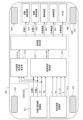
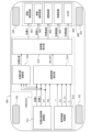
- FIG. 2 is a block diagram showing a vehicle control system.
- FIG. 2 is a diagram illustrating a transient state of vehicle travel.
- FIG. 2 is a two-wheel model diagram for explaining the correlation between the steering angular velocity, acceleration/deceleration, and the vehicle body skid angular velocity ⁇ .
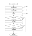
- 4 is a flowchart showing a first embodiment of a control process for a vehicle body side-slip angular velocity ⁇ .
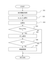
- 10 is a flowchart showing a second embodiment of a control process for a vehicle body side-slip angular velocity ⁇ .
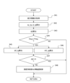
- 10 is a flowchart showing a third embodiment of a control process for a vehicle body side-slip angular velocity ⁇ .
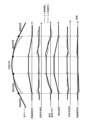
- FIG. 13 is a time chart showing changes in steering angle, longitudinal acceleration, etc., when a third embodiment of a control process for a vehicle body sideslip angular velocity ⁇ is implemented;
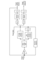
- FIG. 2 is a block diagram showing a vehicle control device that generates a target trajectory as control of a vehicle body sideslip angular velocity ⁇ .
- 4 is a block diagram showing a configuration of a target position conversion unit;
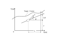
- FIG. 13 is a diagram showing a lateral deviation amount ⁇ at a forward gaze position in a world coordinate system.
- 13 is a flowchart showing a fourth embodiment of a control process for a vehicle body slip angular velocity ⁇ .
- 13 is a time chart showing changes in the steering angles of the front and rear wheels, the longitudinal acceleration, etc., when a fifth embodiment of a control process for a vehicle body sideslip angular velocity ⁇ is carried out.
- 13 is a flowchart showing a fifth embodiment of a control process for a vehicle body side-slip angular velocity ⁇ .
- FIG. 1 is a block diagram showing an embodiment of a vehicle control system 200 mounted on a vehicle 100. As shown in FIG. 1
- the vehicle 100 is a four-wheeled automobile equipped with a pair of left and right front wheels 101, 102 and a pair of left and right rear wheels 103, 104.
- the vehicle control system 200 is an automatic driving system or a driving assistance system having a function of controlling the movement of the vehicle 100 , and includes a vehicle control device 500 and an actuator unit 600 controlled by the vehicle control device 500 .
- the vehicle control device 500 is an electronic control device that includes a microcomputer 510 as a control unit that performs calculations based on input information and outputs the results of the calculations.
- the microcomputer 510 includes a microprocessor unit (MPU), a read only memory (ROM), a random access memory (RAM), and the like, all of which are not shown.
- the microcomputer 510 can be referred to as an MCU (Micro Controller Unit), a processor, a processing device, an arithmetic device, or the like.
- the actuator section 600 is a device that actively changes the behavior of the vehicle 100 .
- the actuator section 600 includes a front wheel steering device 601 that steers the front wheels 101, 102 using a steer-by-wire system, a rear wheel steering device 602 that steers the rear wheels 103, 104, a drive device 603 such as an internal combustion engine or a motor that generates the driving force for the vehicle 100, a braking device 604 that applies braking force to each of the wheels 101-104 of the vehicle 100, and an electronically controlled LSD (Limited-Slip-Differential gear) 605.
- LSD Lited-Slip-Differential gear
- the steer-by-wire system of the front wheel steering device 601 is a steering system in which the steering wheel operated by the driver and the front wheels 101, 102, which are steered wheels, are mechanically separated, and the steering angle of the front wheels 101, 102 is controlled by an electrical signal.
- the front wheel steering device 601, the rear wheel steering device 602, the drive device 603, the brake device 604, and the electronically controlled LSD 605 are all equipped with actuators that can electronically control control variables such as steering angle, drive force, braking force, and differential limiting force by electric signals.
- the main steering mechanism that operates the front wheels 101, 102 is a steering wheel, but this is not limited to this and may be an operation device whose size, shape, etc. are set arbitrarily.
- the vehicle 100 includes a motor as the drive device 603, the motor can be used as a braking device by generating a regenerative braking force.
- the microcomputer 510 of the vehicle control device 500 includes the functional units of a target position information recognition unit 511, a vehicle information recognition unit 512, a ⁇ angular velocity requirement value calculation unit 513, a transition region detection unit 514, and a control amount calculation unit 515 as application programs.
- the target position information recognition unit 511 outputs information regarding the target position ahead of the vehicle 100 (in other words, the forward gaze position), more specifically, information such as the target vehicle speed, which is the target speed of the vehicle 100 at the target position, the target curvature at the target position, the arrival time to the target position (in other words, the forward gaze position time PT), and the distance to the target position (in other words, the forward gaze position distance PD).
- the forward gaze position is set at a position a predetermined distance ahead of the vehicle 100 along the traveling direction of the vehicle 100, and the predetermined distance is a constant value or a distance that increases as the vehicle speed V increases.
- the target position information recognition unit 511 acquires signals from, for example, a GPS (Global Positioning System) receiver that measures the latitude and longitude of the vehicle 100, a database of map information, a wireless communication device that performs road-to-vehicle communication and/or vehicle-to-vehicle communication, a camera that acquires image information about the surroundings of the vehicle 100, a radar or LiDAR (Light Detection and Ranging, Laser Imaging Detection and Ranging) that detects objects around the vehicle 100, and the like, and recognizes information about the target position based on the acquired signals.
- a GPS Global Positioning System
- LiDAR Light Detection and Ranging, Laser Imaging Detection and Ranging
- the vehicle information recognition unit 512 acquires signals from sensors that detect the vehicle state, such as a yaw rate sensor that detects the yaw rate of the vehicle 100, a lateral acceleration sensor that detects the lateral acceleration of the vehicle 100, a steering angle sensor that detects the steering angles of the front and rear wheels (in other words, tire angles), and a wheel speed sensor that detects the rotational speed of each of the wheels 101-104 of the vehicle 100. Based on the outputs of these sensors, the vehicle information recognition unit 512 recognizes information relating to the motion state of the vehicle 100, such as the yaw rate, lateral acceleration, steering angles of the front and rear wheels, and vehicle speed (in other words, vehicle body speed), and outputs a signal of the recognized vehicle information.
- sensors that detect the vehicle state such as a yaw rate sensor that detects the yaw rate of the vehicle 100, a lateral acceleration sensor that detects the lateral acceleration of the vehicle 100, a steering angle sensor that detects the steering angles of the front and rear wheels
- the ⁇ angular velocity required value calculation unit 513, the transition region detection unit 514, and the control amount calculation unit 515 are functional units for executing control of the vehicle body skid angular velocity ⁇ .
- the control of the vehicle body slip angular velocity ⁇ involves controlling at least one of the target steering angular velocity or the target acceleration/deceleration of the vehicle 100 so that the target vehicle body slip angular velocity ⁇ _tg in the transient state when the vehicle 100 is transitioning from a transient state to a steady state has a predetermined time change rate.
- the control of the vehicle body sideslip angular velocity ⁇ involves planning in advance the steering angular velocity or acceleration/deceleration related to the vehicle body sideslip angular velocity ⁇ in a transient state so that the future vehicle body sideslip angular velocity ⁇ has a predetermined time change rate, and changing the steering angle or vehicle speed in accordance with the plan, thereby controlling the time change rate of the vehicle body sideslip angular velocity ⁇ in a transient state.
- the vehicle control device 500 controls the time rate of change of the vehicle body sideslip angular velocity ⁇ in a transient state of vehicle traveling, thereby suppressing fluctuations in vehicle behavior and improving the sense of contact and stability of the vehicle 100.
- the transient state in which control of the vehicle body slip angle velocity ⁇ is performed is a state in which the vehicle body slip angle ⁇ changes, and includes a turning transient state in which the vehicle 100 is traveling through a transitional section of the road, and a state in which the vehicle 100 changes course to change lanes, etc.
- the vehicle body sideslip angle ⁇ [rad] is the angle between the direction of travel of the vehicle 100 and the left-right central axis of the vehicle body
- the vehicle body sideslip angular velocity ⁇ [rad/s] is the time differential value of the vehicle body sideslip angle ⁇ , i.e., the first-order differential value of the vehicle body sideslip angle ⁇ .
- the vehicle body sideslip angular acceleration ⁇ [rad/s 2 ] is the time differential value of the vehicle body sideslip angular velocity ⁇ , that is, the second-order differential value of the vehicle body sideslip angle ⁇ , and corresponds to the time rate of change of the vehicle body sideslip angular velocity ⁇ .
- the ⁇ angular velocity requirement value calculation unit 513 acquires signals of the target vehicle speed, the target curvature at the target position, and the arrival time to the target position (in other words, the forward gaze position time PT) from the target position information recognition unit 511 . Then, the ⁇ angular velocity requirement value calculation unit 513 determines a future target vehicle body slip angular velocity ⁇ _tg based on the acquired signal related to the target position, and outputs a signal of the target vehicle body slip angular velocity ⁇ _tg.
- the target vehicle body slip angular velocity ⁇ _tg can be set to a constant value up to the target position (in other words, the vehicle body slip angular acceleration ⁇ is zero), and such a constant vehicle body slip angular velocity ⁇ can be realized by controlling the target steering angular velocity to a constant value or the target acceleration/deceleration to a constant value.
- the target vehicle body slip angular velocity ⁇ _tg is not limited to a value that is maintained constant up to the target position, and can be set arbitrarily within a range that can improve the sense of contact and stability of the vehicle 100 during the transient state of vehicle travel.
- the transient area detection unit 514 obtains signals of the target vehicle speed, target curvature at the target position, arrival time to the target position (in other words, forward gaze position time PT), and distance to the target position (in other words, forward gaze position distance PD) from the target position information recognition unit 511, and further obtains signals of the yaw rate, lateral acceleration, steering angles of the front and rear wheels, and vehicle speed from the vehicle information recognition unit 512.
- the transitional region detection unit 514 determines whether the traveling state of the vehicle 100 is in a transitional state in which control of the vehicle body skid angular velocity ⁇ should be executed, and outputs a signal instructing the control of the vehicle body skid angular velocity ⁇ to be turned on or off.
- the control amount calculation unit 515 obtains a signal of the target vehicle body slip angular velocity ⁇ _tg from the ⁇ angular velocity requirement value calculation unit 513, and obtains a signal instructing the control of the vehicle body slip angular velocity ⁇ to be turned on or off (in other words, a signal indicating the result of the determination as to whether or not the vehicle is in a transient state) from the transient region detection unit 514.
- the control quantity calculation unit 515 receives a signal from the transient region detection unit 514 instructing the implementation of control of the vehicle body slip angular velocity ⁇ , it outputs signals of the target steering angle and the target rotational speed (in other words, the target wheel speed) based on the target vehicle body slip angular velocity ⁇ _tg to the actuator unit 600.
- the vehicle control device 500 generates a vehicle motion plan for setting the vehicle body sideslip angular velocity ⁇ at a predetermined time rate of change based on route information ahead of the vehicle, and controls the steering angle and vehicle speed based on the generated vehicle motion plan.
- FIG. 2 is a diagram showing a curved road in which a transition section, which is a transition region in which control of the vehicle body sideslip angular velocity ⁇ is executed, is set.
- the road in FIG. 2 has a transition section (more specifically, a clothoid section) between a circular arc section (in other words, a steady turning section) and a straight section.
- the arc section is a section in which the curvature ⁇ , i.e., the turning radius R, is constant
- the transition section is a section in which the curvature ⁇ changes at a constant rate depending on the distance (in other words, the length of the curve).
- the vehicle control device 500 executes control of the vehicle body slip angular velocity ⁇ in the first transition section when transitioning from the first transition section to the arc section, or in the second transition section when transitioning from the second transition section to the straight section.
- the vehicle control device 500 can control at least one of the target steering angular velocity or the target acceleration/deceleration of the vehicle 100, for example, so that the vehicle body slip angular velocity ⁇ is maintained at a constant value, in other words, so that the target vehicle body slip angular acceleration ⁇ , which is the time derivative value of the vehicle body slip angular velocity ⁇ , is maintained at zero, during the transient state in which the vehicle 100 is traveling through the mitigation section.
- the vehicle control device 500 sets the vehicle body slip angular acceleration ⁇ in the transition zone to zero, in other words, when the vehicle body slip angular velocity ⁇ is a constant value, the vehicle control device 500 sets the target steering angular velocity or the target acceleration/deceleration in the transition zone to a constant value.
- the vehicle control device 500 plans in advance the steering angular velocity and acceleration/deceleration from the beginning of the transient state to the transition to the steady state so that the vehicle slip angle ⁇ changes at a constant angular velocity during the process from the initial vehicle slip angle ⁇ _in (current value) in the first driving state at the beginning of the transient state to the target vehicle slip angle ⁇ _tg (predicted value) in the second driving state where the transition from the transient state to the steady state takes place.
- the vehicle control device 500 determines the target vehicle body slip angular velocity ⁇ _tg at which the vehicle body slip angle ⁇ changes at a constant angular velocity and the vehicle body slip angular acceleration ⁇ becomes zero based on the initial vehicle body slip angle ⁇ _in and the target vehicle body slip angle ⁇ _tg, and sets the target steering angular velocity or target acceleration/deceleration so that the vehicle body slip angle ⁇ changes at this target vehicle body slip angular velocity ⁇ _tg. This suppresses fluctuations in the vehicle body skid angular velocity ⁇ during a transient state while the vehicle 100 is traveling, improving the vehicle's feeling of contact with the ground and stability.
- the first driving state at the beginning of the transient state is, for example, when the vehicle 100 starts turning, and in the case of the road in Figure 2, it is when the vehicle 100 enters a transition section from a straight section and the steering angle starts to be increased.
- the second driving state in which the vehicle transitions from a transient state to a steady state is, for example, when the vehicle 100 starts turning and then turns steadily, which, in the case of the road in Figure 2, is the time of maximum curvature when the vehicle 100 enters the arc section from the transition section.
- the first driving state at the beginning of the transient state is, for example, when the vehicle 100 starts increasing or decreasing the steering angle or accelerating or decelerating after completing a steady turn, and in the case of the road in Figure 2, it is when the vehicle 100 enters the transition section from the arc section and starts turning back the steering angle.
- the second driving state in which the vehicle 100 transitions from a transient state to a steady state is, for example, a state in which the vehicle 100 travels straight after completing a steady turn; in the case of the road in FIG. 2, this is when the vehicle 100 leaves the transition section and enters a straight section, and the vehicle body sideslip angle ⁇ returns to zero.
- the transient region detection unit 514 obtains information regarding the motion state of the vehicle 100, such as yaw rate, lateral acceleration, steering angles of the front and rear wheels, and wheel speed, from the vehicle information recognition unit 512, and further obtains information regarding the forward gaze position, such as the target vehicle speed, target curvature, time to the forward gaze position, and distance to the forward gaze position, from the target position information recognition unit 511.
- the transition region detection unit 514 calculates the current vehicle body skid angular velocity ⁇ based on the various acquired information, and further calculates the target lateral acceleration ⁇ y_tg at the forward gaze position.
- the transient region detection unit 514 determines that the vehicle 100 is in a transient state and outputs a signal to the control amount calculation unit 515 to command the implementation of control of the vehicle body skid angular velocity ⁇ .
- the lateral acceleration ⁇ y_tg, yaw rate ⁇ _tg, and vehicle body sideslip angle ⁇ _tg in a steady circle without centrifugal force can be calculated as shown in Equation 1.
- the information on the curvature at the forward gaze position is information on the maximum curvature if it is a transition section just before a circular arc section.
- the transient region detection unit 514 can detect a situation in which the curvature ⁇ will increase in the future and the vehicle slip angle ⁇ will increase, or a situation in which the curvature ⁇ will decrease in the future and the vehicle slip angle ⁇ will decrease. Furthermore, if the current vehicle body slip angle velocity ⁇ is not zero, the transient region detection unit 514 can detect that the vehicle 100 is in a transient state, and issues a command to control the vehicle body slip angle velocity ⁇ in order to deal with future changes in the vehicle body slip angle ⁇ .
- a ⁇ angular velocity requirement calculation unit 513 calculates, based on the initial vehicle body slip angle ⁇ _in, the target vehicle body slip angle ⁇ _tg, and the predicted arrival time to the position of the target vehicle body slip angle ⁇ _tg, as a target vehicle body slip angular velocity ⁇ _tg, and outputs a signal of the target vehicle body slip angular velocity ⁇ _tg to a control variable calculation unit 515.
- the target vehicle body sideslip angular velocity ⁇ _tg being a constant value corresponds to the target vehicle body sideslip angular acceleration ⁇ _tg being zero.
- the control amount calculation unit 515 outputs a control target for changing the vehicle body slip angle ⁇ at the target vehicle body slip angle velocity ⁇ _tg to the actuator unit 600.
- the control amount calculation unit 515 calculates a target steering angle in accordance with a target steering angular velocity for changing the vehicle body slip angle ⁇ at the target vehicle body slip angle velocity ⁇ _tg, and a target rotational angular velocity (in other words, a target wheel speed) in accordance with a target acceleration/deceleration for changing the vehicle body slip angle ⁇ at the target vehicle body slip angular velocity ⁇ _tg, and outputs a signal of the target steering angle and a signal of the target rotational angular velocity to the actuator unit 600.
- the target vehicle body skid angular velocity ⁇ _tg is a constant value
- the target steering angle and the target acceleration/deceleration are constant.
- ⁇ is the yaw rate
- ⁇ f is the front wheel slip angle
- ⁇ r is the rear wheel slip angle
- L is the wheelbase
- Lf is the distance from the center of gravity to the front axle
- Lr is the distance from the center of gravity to the rear axle
- m is the vehicle weight
- Yf is the front wheel lateral force
- Yr is the rear wheel lateral force.
- the lateral acceleration ⁇ y is calculated based on the vehicle body sideslip angular velocity ⁇ , the yaw rate ⁇ , and the vehicle speed V according to Equation 2.
- the front wheel slip angle ⁇ f and the rear wheel slip angle ⁇ r are obtained according to Equation 3.
- the yaw rate ⁇ is expressed using the front wheel sideslip angle ⁇ f and the rear wheel sideslip angle ⁇ r as in Equation 4
- the vehicle body sideslip angle ⁇ is expressed using the front wheel sideslip angle ⁇ f and the rear wheel sideslip angle ⁇ r as in Equation 5.
- Equation 4 and Equation 5 are differentiated, Equation 6 and Equation 7 are obtained.
- Equation 9 The equation of motion expressing the two-degree-of-freedom motion with the front wheel sideslip angle ⁇ f and the rear wheel sideslip angle ⁇ r is given by Equation 9, where the front wheel steering angle is ⁇ , the rear wheel steering angle is ⁇ r, and the cornering coefficients of the front and rear wheels are Cf and Cr.
- the vehicle body slip angular velocity ⁇ changes according to the front wheel slip angular velocity ⁇ f and the rear wheel slip angular velocity ⁇ r.
- the front wheel slip angular velocity ⁇ f and the rear wheel slip angular velocity ⁇ r vary depending on the front wheel steering angle ⁇ , the rear wheel steering angle ⁇ r, and the vehicle speed V.
- the vehicle control device 500 can control the vehicle body slip angular velocity ⁇ in a transient state, and further, by controlling the target steering angular velocity and the target acceleration/deceleration, can control the target vehicle body slip angular velocity ⁇ _tg to a predetermined time change rate when the vehicle body slip angle ⁇ changes toward the target vehicle body slip angle ⁇ _tg. Furthermore, the vehicle control device 500 controls the target vehicle body slip angular velocity ⁇ _tg during the transient state of the vehicle 100's driving to a predetermined time change rate, thereby preventing fluctuations in vehicle behavior during the transient state, and improving the sense of contact and stability of the vehicle 100.
- FIG. 4 is a flowchart showing a control process when the vehicle control device 500 controls the target steering angular velocities of the front and rear wheels so that the target vehicle body skid angular velocity ⁇ _tg becomes constant in a transient state.
- step S21 the vehicle control device 500 acquires information on the target vehicle speed at the forward gaze position, the road curvature, the distance to the forward gaze position, and the time from the route information of the vehicle 100.
- step S22 the vehicle control device 500 calculates the lateral acceleration ⁇ y at the forward gaze position of the vehicle 100, i.e., the position of maximum curvature, from the target vehicle speed, curvature, and time to the forward gaze position as the target lateral acceleration ⁇ y_tg.
- step S22 the vehicle control device 500 calculates a target vehicle body slip angle ⁇ _tg, which is the vehicle body slip angle ⁇ at the forward gaze position, based on the target lateral acceleration ⁇ y_tg and the target vehicle speed.
- the vehicle control device 500 When the vehicle control device 500 is able to acquire information on the road shape ahead of the vehicle 100, it identifies the position of maximum curvature of the curve ahead, and determines the target lateral acceleration ⁇ y_tg and the target vehicle body sideslip angle ⁇ _tg from the information on the maximum curvature.
- the maximum curvature position is the end point of the transition section, and the maximum curvature is the curvature of the circular arc section.
- the vehicle control device 500 sets the target vehicle body slip angle ⁇ _tg and the target lateral acceleration ⁇ y_tg to zero.
- step S23 the vehicle control device 500 calculates the current vehicle body skid angular velocity ⁇ based on the detected value of the vehicle speed V and the detected value of the lateral acceleration ⁇ y (in other words, the current lateral acceleration ⁇ y_ac). Then, in step S24, the vehicle control device 500 determines, as the first condition for determining whether the vehicle 100 is in a transient state, whether the absolute value of the difference D ⁇ y between the target lateral acceleration ⁇ y_tg and the current lateral acceleration ⁇ y_ac is greater than or equal to a predetermined value TH ⁇ y (TH ⁇ y > 0).
- the vehicle control device 500 proceeds to step S25 and subsequent steps.
- the vehicle control device 500 ends this routine without controlling the vehicle body skid angle velocity ⁇ .
- step S25 the vehicle control device 500 calculates a target steering angular velocity ⁇ _tg for changing the vehicle body slip angle ⁇ from the current vehicle body slip angle ⁇ (in other words, the initial vehicle body slip angle ⁇ _in) to the target vehicle body slip angle ⁇ _tg at the target vehicle body slip angle velocity ⁇ _tg.
- the vehicle control device 500 calculates the target steering angular velocity ⁇ _tg that changes the steering angle from the current steering angle to the target steering angle at the target vehicle body slip angle ⁇ _tg at a constant angular velocity.
- the vehicle control device 500 sets the target steering angular velocity ⁇ _tg in a transient state to a constant value, thereby making the target vehicle body skid angular velocity ⁇ _tg in a transient state a constant value.
- step S26 the vehicle control device 500 determines, as a second condition for determining whether the vehicle 100 is in a transient state, whether the current vehicle body skid angular velocity ⁇ is less than or equal to a predetermined value, for example, whether the current vehicle body skid angular velocity ⁇ is zero. That is, in step S26, the vehicle control device 500 determines whether the vehicle body sideslip angle ⁇ is changing or whether the vehicle body sideslip angle ⁇ is maintaining a constant value.
- the vehicle control device 500 proceeds to step S27 and executes control to change the steering angle in accordance with the target steering angular velocity ⁇ _tg calculated in step S25.
- step S27 the vehicle control device 500 determines a steering angular velocity gain based on the target steering angular velocity ⁇ _tg, and outputs a steering control current based on the steering angular velocity gain to each of the front wheel steering device 601 and the rear wheel steering device 602.
- the vehicle control device 500 can control only the front wheel steering device 601 out of the front wheel steering device 601 and the rear wheel steering device 602.
- the vehicle control device 500 determines the vehicle body slip angular velocity ⁇ in step S26, in other words, determines whether to start control of the vehicle body slip angular velocity ⁇ .
- the calculation process of the target steering angular velocity ⁇ _tg is repeated in preparation for the start of control, thereby preventing a delay in the calculation cycle of the control amount when it is determined that control should be started.
- the vehicle control device 500 ends this routine without controlling the vehicle body skid angular velocity ⁇ .
- the vehicle control device 500 waits by repeating the calculation process of the target steering angular velocity ⁇ _tg until the vehicle enters a transitional state.
- the vehicle control device 500 carries out the process shown in the flowchart of FIG. 4 to change the steering angle along a constant target steering angular velocity ⁇ _tg in a transient state, such as when driving in a transition section, thereby suppressing fluctuations in the vehicle body slip angular velocity ⁇ in the transient state.
- FIG. 5 is a flowchart showing a control process when the vehicle control device 500 controls the target acceleration/deceleration of the vehicle 100 so that the vehicle body sideslip angular velocity ⁇ becomes constant in a transient state.
- steps S31 to S34 in the flowchart of FIG. 5 the same processes as in steps S21 to S24 in the flowchart of FIG. 4 are carried out, and therefore detailed description thereof will be omitted here.
- step S34 the vehicle control device 500 determines in step S34 that the difference D ⁇ y is equal to or greater than the predetermined value TH ⁇ y.
- the process proceeds to step S35.
- step S35 the vehicle control device 500 calculates a target acceleration/deceleration AD_tg for changing the vehicle body slip angle ⁇ from the current vehicle body slip angle ⁇ (in other words, the initial vehicle body slip angle ⁇ _in) to the target vehicle body slip angle ⁇ _tg at the target vehicle body slip angle velocity ⁇ _tg.
- the vehicle control device 500 calculates a target acceleration/deceleration AD_tg that changes the vehicle speed from the current time to the target vehicle speed at the target vehicle body slip angle ⁇ _tg at a constant acceleration/deceleration.
- the vehicle control device 500 sets the target acceleration/deceleration AD_tg in a transient state to a constant value, thereby keeping the target vehicle body slip angular velocity ⁇ _tg in a transient state at a constant value.
- step S36 the vehicle control device 500 determines whether the current vehicle body skid angular velocity ⁇ is zero, similarly to step S26. Then, when the vehicle control device 500 determines in step S36 that the current vehicle body skid angular velocity ⁇ is not zero, the process proceeds to step S37.
- step S37 the vehicle control device 500 executes control to change the vehicle speed in accordance with the target acceleration/deceleration AD_tg calculated in step S35. Specifically, in step S37, the vehicle control device 500 determines the rotation speed gain based on the target acceleration/deceleration AD_tg. During acceleration, the vehicle control device 500 outputs a drive control current based on the rotation speed gain to the drive device 603, and during deceleration, outputs a brake control current based on the rotation speed gain to the brake device 604. As described above, the vehicle control device 500 carries out the process shown in the flowchart of FIG.
- FIG. 6 is a flowchart showing a control process when the vehicle control device 500 controls both the target steering angular velocity and the target acceleration/deceleration so that the vehicle body sideslip angular velocity ⁇ becomes constant in a transient state.
- steps S41 to S44 in the flowchart of FIG. 6 the same processes as those in steps S21 to S24 in the flowchart of FIG. 4 are carried out, and therefore detailed description thereof will be omitted here.
- step S44 When the vehicle control device 500 determines in step S44 that the difference D ⁇ y is equal to or greater than the predetermined value TH ⁇ y, it performs the process of step S45 and the process of step S46 in parallel.
- step S45 the vehicle control device 500 determines the target steering angular velocity ⁇ _tg in the same manner as in step S25, and in step S46, determines the target acceleration/deceleration AD_tg in the same manner as in step S35.
- step S47 the vehicle control device 500 determines whether the current vehicle body skid angular velocity ⁇ is zero, similarly to step S26. If the vehicle control device 500 determines in step S47 that the current vehicle body skid angular velocity ⁇ is not zero, the process proceeds to step S48.
- step S48 similar to step S27, the vehicle control device 500 determines a steering angular velocity gain based on the target steering angular velocity ⁇ _tg, and outputs steering control currents based on the steering angular velocity gains to the front wheel steering device 601 and the rear wheel steering device 602, respectively. Furthermore, in step S48, as in step S37, the vehicle control device 500 determines a rotational speed gain based on the target acceleration/deceleration AD_tg, and if accelerating, outputs a drive control current based on the rotational speed gain to the drive device 603, and if decelerating, outputs a braking control current based on the rotational speed gain to the braking device 604.
- the vehicle control device 500 carries out the process shown in the flowchart of FIG. 6 to change the steering angle based on a constant target steering angular velocity ⁇ _tg and to change the vehicle speed (wheel speed) in accordance with a constant target acceleration/deceleration AD_tg in a transient state, such as when driving in a transition section, thereby suppressing fluctuations in vehicle body skid angular velocity ⁇ in the transient state.
- the time chart in Figure 7 illustrates changes in front wheel steering angle, wheel rotational speed, vehicle body sideslip angle ⁇ , lateral acceleration, and longitudinal acceleration when vehicle 100 travels along a curved road that goes from a straight section ⁇ transition section ⁇ arc section ⁇ transition section ⁇ straight section.
- the solid line in Figure 7 indicates a state in which the vehicle control device 500 performs control of the vehicle body skid angular velocity ⁇ (more specifically, control that keeps the target steering angular velocity and the target acceleration/deceleration constant), and the dotted line in Figure 7 indicates a state in which control of the vehicle body skid angular velocity ⁇ is not performed.
- the vehicle body slip angle ⁇ will move unstably in accordance with changes in the steering angular velocity and acceleration/deceleration during the transitional state in which the vehicle 100 is traveling through the transition section, reducing the sense of contact with the ground and stability of the vehicle 100.
- the target steering angular velocity and target acceleration/deceleration are controlled to be constant in the transient state, so that the vehicle body slip angle ⁇ changes at a constant angular velocity ⁇ , improving the sense of contact and stability of the vehicle 100 in the transient state.
- the vehicle control device 500 can generate a target trajectory of the vehicle 100 based on a target position of the vehicle 100 such that the target vehicle body skid angular velocity ⁇ _tg has a predetermined time change rate.
- the vehicle control device 500 can generate a target trajectory incorporating a target steering angular velocity ⁇ _tg or a target acceleration/deceleration AD_tg such that the target vehicle body slip angular velocity ⁇ _tg has a predetermined time change rate, and control the actuator unit 600 to trace such a target trajectory.
- FIG. 8 is a block diagram showing a vehicle control device 500 that generates a target trajectory as control of the vehicle body sideslip angular velocity ⁇ .
- the vehicle control device 500 shown in FIG. 8 has a target position conversion unit 516 instead of the ⁇ angular velocity required value calculation unit 513 included in the vehicle control device 500 shown in FIG.
- the target position conversion unit 516 is a functional unit that determines a target vehicle position incorporating the vehicle body skid angular velocity ⁇ _tg.
- FIG. 9 is a block diagram showing in detail the signal transmission path in the target position conversion unit 516.
- FIG. 10 is a diagram showing, in the world coordinate system, the lateral deviation ⁇ of the vehicle 100 from the target trajectory when the vehicle 100 is in the forward gaze position.
- a target position conversion unit 516 converts the lateral deviation ⁇ into a steering angle ⁇ , and obtains the vehicle body lateral slip angle ⁇ and yaw rate ⁇ according to Equations 10 and 11.
- the target position conversion unit 516 obtains the forward vehicle speed and the lateral vehicle speed from the vehicle body sideslip angle ⁇ and yaw rate ⁇ according to Equations 12 and 13.
- the target position conversion unit 516 adds the target vehicle body slip angular velocity ⁇ _tg to determine the forward vehicle position x and lateral vehicle position y that represent the target vehicle position according to Formula 14 and Formula 15, and outputs information on this target vehicle position (more specifically, the forward vehicle position x and lateral vehicle position y) to the control amount calculation unit 515 as information on the target trajectory.
- the control amount calculation unit 515 controls the actuator unit 600 so that the vehicle passes through the acquired target vehicle position.
- FIG. 11 is a flowchart showing a control process when a target trajectory is planned taking into account the target vehicle body slip angular velocity ⁇ _tg.
- steps S51 to S54 in the flowchart of FIG. 11 the same processes as in steps S21 to S24 in the flowchart of FIG. 4 are carried out, and therefore detailed description thereof will be omitted here.
- step S54 the vehicle control device 500 calculates the target vehicle position incorporating the target vehicle body skid angular velocity ⁇ _tg. As described above, the target vehicle position is calculated by the target position conversion unit 516 shown in FIG.
- step S56 the vehicle control device 500 calculates control amounts that are target values for each device for making the vehicle 100 follow the target vehicle position incorporating the target vehicle body skid angular velocity ⁇ _tg. Then, in step S57, the vehicle control device 500 determines whether the vehicle body skid angular velocity ⁇ at the current time is zero, thereby determining whether the vehicle 100 is in a transient state.
- the vehicle control device 500 proceeds to step S58, and controls the braking/driving force based on the control amount calculated in step S56, and also controls the steering angles of the front and rear wheels, thereby causing the vehicle 100 to follow the target vehicle position incorporating the target vehicle body skid angular velocity ⁇ _tg.
- the vehicle control device 500 can realize, for example, transient driving in which the target vehicle body slip angular velocity ⁇ _tg is constant, and the sense of contact and stability of the vehicle 100 in a transient state of vehicle driving can be improved.
- the target vehicle body sideslip angular velocity ⁇ _tg is set to a constant value
- the target trajectory incorporating the target vehicle body sideslip angular velocity ⁇ _tg becomes a target trajectory in which the target steering angular velocity and the target acceleration/deceleration are constant in the transition region.
- control of the vehicle body slip angular velocity ⁇ performed by the vehicle control device 500 is not limited to control in which the target vehicle body slip angular velocity ⁇ _tg in a transient state is set to a constant value, that is, control in which the target vehicle body slip angular acceleration ⁇ _tg in a transient state is set to zero.
- FIG. 12 is a time chart showing an example of target vehicle body slip angular velocity ⁇ _tg that is not a constant value in a transient state.
- the target vehicle body slip angle velocity ⁇ _tg is set so that at the beginning of the transition region, specifically, when the vehicle 100 first enters the transition section from the straight section and when the vehicle 100 first enters the transition section from the arc section, the vehicle body slip angle ⁇ changes at a constant angular velocity in the direction toward the outward side of the turn. Thereafter, the target vehicle body slip angle velocity ⁇ _tg is set so that the direction of change of the vehicle body slip angle ⁇ reverses at a certain angle and returns to zero, and the target vehicle body slip angle ⁇ changes at a constant angular velocity toward the vehicle body slip angle ⁇ at maximum curvature on the side where the vehicle body faces inward during turning.
- the target vehicle body slip angle velocity ⁇ _tg is set in the opposite direction to the vehicle body slip angle ⁇ at the forward gaze position at the beginning of the transition region, and then reverses to the direction toward the vehicle body slip angle ⁇ at the forward gaze position.
- the sense of contact of vehicle 100 with the ground can be improved by first changing vehicle body slip angle ⁇ to the side where the vehicle turns outward and then changing it toward vehicle body slip angle ⁇ at the forward gaze position, rather than changing vehicle body slip angle ⁇ toward vehicle body slip angle ⁇ at the forward gaze position from the point where vehicle 100 enters the transition region.
- the target vehicle body slip angle velocity ⁇ _tg when the vehicle 100 initially enters the transition section from the straight section is set so that the magnitude of the vehicle body slip angle ⁇ on the side where the vehicle body turns outward is not larger than when control of the vehicle body slip angle velocity ⁇ is not implemented, and further, after the vehicle body slip angle ⁇ returns to zero, it is set so that it is changed at a constant angle toward the vehicle body slip angle ⁇ at maximum curvature.
- the vehicle control device 500 can variably set the target vehicle body slip angle velocity ⁇ _tg and the target period when changing the vehicle body slip angle ⁇ in the reverse direction at the beginning of the transition period depending on the rate of change of the curvature, the vehicle speed, etc. Furthermore, the target vehicle body slip angle velocity ⁇ _tg when the vehicle body slip angle ⁇ is changed from zero toward the vehicle body slip angle ⁇ at the maximum curvature is not limited to a constant value, and changes in the angular velocity within a predetermined range are permitted.
- the vehicle control device 500 can control the change in the vehicle body slip angle ⁇ on the side where the vehicle body will turn outward by implementing control to reduce the longitudinal acceleration and control to steer the rear wheels 103, 104 in opposite phases.
- the microcomputer 510 controls the difference in braking/driving force between the left and right wheels, thereby controlling the turning moment generated in the vehicle 100 and controlling the change in the vehicle body sideslip angle ⁇ on the side where the vehicle body faces outward during a turn.
- FIG. 13 is a flowchart showing a control process when the vehicle control device 500 controls the target steering angular velocities and the target acceleration/deceleration of the front and rear wheels so that the target vehicle body skid angular velocity ⁇ _tg in a transient state has a predetermined time rate of change such as that shown in FIG.
- steps S61 to S64 in the flowchart of FIG. 13 the same processes as in steps S21 to S24 in the flowchart of FIG. 4 are carried out, and therefore detailed description thereof will be omitted here.
- step S64 When the vehicle control device 500 determines in step S64 that the transient judgment condition is satisfied, that is, that the difference between the target lateral acceleration ⁇ y_tg and the current lateral acceleration ⁇ y_ac is greater than or equal to a predetermined value, it executes the processing in step S65 and the processing in step S66 in parallel.
- step S65 the vehicle control device 500 calculates a target steering angular velocity ⁇ _tg toward the forward gaze position in a time series manner so that the target vehicle body skid angular velocity ⁇ _tg has a predetermined time change rate, for example, as shown in FIG.
- a target steering angular velocity ⁇ _tg is calculated that makes the steering angles of the rear wheels 103, 104 in opposite phases at the beginning of the transition period.
- step S66 the vehicle control device 500 calculates the target acceleration/deceleration AD_tg toward the forward gaze position in a time series manner so that the target vehicle body skid angular velocity ⁇ _tg has a predetermined time change rate, for example, as shown in FIG.
- the vehicle control device 500 can generate a turning moment by controlling the difference in braking/driving force between the left and right wheels and by controlling the electronically controlled LSD in order to change the vehicle body sideslip angle ⁇ so that the vehicle body turns outward at the beginning of the transition.
- step S67 After calculating the target steering angular velocity ⁇ _tg and the target acceleration/deceleration AD_tg, the vehicle control device 500 proceeds to step S67, where it is determined whether the current vehicle body sideslip angular velocity ⁇ is zero.
- the vehicle control device 500 proceeds to step S68 and executes control of the vehicle body skid angular velocity ⁇ .
- step S68 the vehicle control device 500 determines a wheel rotational speed gain based on the target acceleration/deceleration AD_tg at that time, and outputs a braking/driving control current to each of the drive device 603 and the braking device 604, and also determines a steering angular velocity gain based on the target steering angular velocity ⁇ _tg at that time, and outputs a steering control current to each of the front wheel steering device 601 and the rear wheel steering device 602.
- the vehicle control device 500 ends this routine without performing control of the vehicle body skid angular velocity ⁇ .
- the vehicle control device 500 controls the target steering angular velocity and the target acceleration/deceleration so that the target vehicle body skid angular velocity ⁇ _tg has a predetermined time rate of change that is not a constant value, thereby making it possible to further improve the vehicle's sense of contact with the ground and stability compared to when the values are constant.
- the above condition for vehicle speed V is intended to perform control of vehicle body skid angular velocity ⁇ at medium to high vehicle speeds that can contribute to improving the feeling of contact with the ground and stability. Adding the condition for vehicle speed V makes it possible to prevent ineffective control from being unnecessarily performed at low vehicle speeds.
- the vehicle control device 500 can control the throttle opening degree in accordance with the target acceleration/deceleration. Furthermore, the vehicle 100 can implement control of the vehicle body skid angular velocity ⁇ either when the vehicle 100 enters the transition section from a straight section or when the vehicle 100 enters the transition section from a circular arc section.
Landscapes
- Engineering & Computer Science (AREA)
- Chemical & Material Sciences (AREA)
- Combustion & Propulsion (AREA)
- Transportation (AREA)
- Mechanical Engineering (AREA)
- Physics & Mathematics (AREA)
- Mathematical Physics (AREA)
- Automation & Control Theory (AREA)
- Theoretical Computer Science (AREA)
- Steering Control In Accordance With Driving Conditions (AREA)
- Control Of Driving Devices And Active Controlling Of Vehicle (AREA)
Abstract
Description
本発明は、車両制御装置、及び、車両制御方法に関する。 The present invention relates to a vehicle control device and a vehicle control method.
特許文献1の車両用操舵装置は、ステアリングホイールで前輪を操舵する主操舵機構と、車両の走行状態に応じて前輪舵角若しくは後輪を電動機などのアクチュエータで操舵する補助操舵機構とを有し、さらに、後車軸よりも前方のある点での車体横滑り角速度を検出または推定する車体横滑り角速度演算部と、車体横滑り角速度の絶対値を減少させるようにアクチュエータを制御する制御手段とを有する。
The vehicle steering device of
ところで、車体横滑り角速度の検出値または推定値の絶対値を減少させるように操舵機構が制御される場合、車両の将来的な走行状態が考慮されないことから、たとえば、道路曲率が徐々に変化する緩和区間を車両が走行する過渡状態において車両挙動の変動が発生して、車両の接地感、安定感が低下する可能性があった。 However, when the steering mechanism is controlled to reduce the absolute value of the detected or estimated vehicle body sideslip angular velocity, the vehicle's future driving state is not taken into consideration. For example, in a transitional state where the vehicle is driving through a transition section where the road curvature gradually changes, fluctuations in vehicle behavior may occur, resulting in a decrease in the vehicle's sense of contact with the ground and stability.
本発明は、従来の実情に鑑みてなされたものであり、その目的は、車両走行の過渡状態における車両の接地感、安定感を向上させることができる、車両制御装置、及び、車両制御方法を提供することにある。 The present invention was made in consideration of the current situation, and its purpose is to provide a vehicle control device and a vehicle control method that can improve the vehicle's sense of contact with the ground and stability during transient states of vehicle driving.
本発明に係る車両制御装置によれば、その1つの態様において、車両の走行が過渡状態から定常状態へ遷移するときの前記過渡状態における目標車体横滑り角速度が所定の時間変化率になるように、前記車両の目標操舵角速度、または目標加減速度のうち少なくとも一方を制御する。
また、本発明に係る車両制御方法によれば、その1つの態様において、車両が旋回を開始してから定常旋回になるまでの区間において、前記車両の目標操舵角速度及び目標加減速度を一定に制御する。
In one aspect of the vehicle control device according to the present invention, at least one of a target steering angular velocity or a target acceleration/deceleration of the vehicle is controlled so that a target vehicle body sideslip angular velocity in a transient state when the vehicle's traveling transitions from a transient state to a steady state becomes a predetermined time change rate.
In one aspect of the vehicle control method according to the present invention, a target steering angular velocity and a target acceleration/deceleration of the vehicle are controlled to be constant during a period from when the vehicle starts turning until the vehicle reaches a steady turn.
本発明によれば、車両走行の過渡状態における車両の接地感、安定感を向上させることができる。 The present invention can improve the vehicle's sense of contact with the ground and stability during transient vehicle driving conditions.
以下、本発明に係る車両制御装置、及び、車両制御方法の実施形態を、図面に基づいて説明する。
図1は、車両100に搭載される車両制御システム200の一態様を示すブロック図である。
DETAILED DESCRIPTION OF THE PREFERRED EMBODIMENTS Hereinafter, embodiments of a vehicle control device and a vehicle control method according to the present invention will be described with reference to the drawings.
FIG. 1 is a block diagram showing an embodiment of a vehicle control system 200 mounted on a
車両100は、左右一対の前輪101,102、及び、左右一対の後輪103,104を備えた4輪自動車である。
車両制御システム200は、車両100の運動を制御する機能を有した自動運転システム若しくは運転支援システムであって、車両制御装置500と、車両制御装置500によって制御されるアクチュエータ部600を備える。
The
The vehicle control system 200 is an automatic driving system or a driving assistance system having a function of controlling the movement of the
車両制御装置500は、入力した情報に基づいて演算を行って演算結果を出力するコントロール部としてのマイクロコンピュータ510を備える電子制御装置である。
マイクロコンピュータ510は、図示を省略したMPU(Microprocessor Unit)、ROM(Read Only Memory)、RAM(Random Access Memory)などを備える。
なお、マイクロコンピュータ510は、MCU(Micro Controller Unit)、プロセッサ、処理装置、演算装置などと言い換えることができる。
The
The
The
アクチュエータ部600は、車両100の挙動を能動的に変化させるデバイスである。
アクチュエータ部600は、ステアバイワイヤ方式で前輪101,102を操舵する前輪操舵装置601、後輪103,104を操舵する後輪操舵装置602、車両100の駆動力を発生する内燃機関やモータなどの駆動装置603、車両100の各車輪101-104に制動力を付与する制動装置604、電子制御式LSD(Limited-Slip-Differential gear)605を備える。
The
The
前輪操舵装置601のステアバイワイヤ方式とは、運転者が操作するステアリングホイールと、転舵輪である前輪101,102とが機械的に切り離され、電気信号で前輪101,102の操舵角を制御する操舵システムである。
なお、前輪操舵装置601、後輪操舵装置602、駆動装置603、制動装置604、及び、電子制御式LSD605は、いずれも電気信号によって、操舵角、駆動力、制動力、差動制限力などの制御量を電子制御することが可能なアクチュエータを備える。ここで、本実施形態では、前輪101,102を操作する主操舵機構をステアリングホイールとしているが、これに限らず、その大きさ、形状等を任意に設定した操作デバイスであっても構わない。
また、車両100が駆動装置603としてモータを備える場合、モータで回生制動力を発生させることで、モータを制動装置として用いることが可能である。
The steer-by-wire system of the front
The front
Furthermore, when the
車両制御装置500のマイクロコンピュータ510は、目標位置情報認識部511、車両情報認識部512、β角速度要求値算出部513、過渡領域検知部514、制御量算出部515の各機能部をアプリケーションプログラムとして備える。
目標位置情報認識部511は、車両100の前方の目標位置(換言すれば、前方注視位置)に関する情報、詳しくは、目標位置での車両100の目標速度である目標車速、目標位置での目標曲率、目標位置までの到達時間(換言すれば、前方注視位置時間PT)、目標位置までの距離(換言すれば、前方注視位置距離PD)などの情報を出力する。
なお、前方注視位置は、車両100の進行方向に沿って所定距離だけ車両100の前方の位置に設定され、所定距離は、一定値、または、車速Vが高くなるにつれて増加する距離である。
The
The target position
The forward gaze position is set at a position a predetermined distance ahead of the
目標位置情報認識部511は、たとえば、車両100の緯度及び経度を測定するGPS(Global Positioning System)受信部、地図情報のデータベース、路車間通信及び/または車車間通信を行う無線通信装置、車両100の周囲の画像情報を取得するカメラ、車両100の周囲の物体を検出するレーダやLiDAR(Light Detection and Ranging、Laser Imaging Detection and Ranging)などからの信号を取得し、取得した信号に基づいて目標位置に関する情報を認識する。
The target position
車両情報認識部512は、たとえば、車両100のヨーレイトを検出するヨーレイトセンサ、車両100の横加速度を検出する横加速度センサ、前輪及び後輪の操舵角(換言すれば、タイヤ角)を検出する操舵角センサ、車両100の車輪101-104それぞれの回転速度を検出する車輪速センサなどの車両状態を検出するセンサからの信号を取得する。
そして、車両情報認識部512は、これらのセンサの出力に基づき、車両100の運動状態に関する情報であるヨーレイト、横加速度、前後輪の操舵角、車速(換言すれば、車体速)を認識し、認識した車両情報の信号を出力する。
The vehicle
Based on the outputs of these sensors, the vehicle
β角速度要求値算出部513、過渡領域検知部514、及び、制御量算出部515は、車体横滑り角速度Δβの制御を実行するための機能部である。
車体横滑り角速度Δβの制御は、後で詳細に説明するように、車両100の走行が過渡状態から定常状態へ遷移するときの前記過渡状態における目標車体横滑り角速度Δβ_tgが所定の時間変化率になるように、車両100の目標操舵角速度、または目標加減速度のうち少なくとも一方を制御する。
The β angular velocity required
As will be described in detail later, the control of the vehicle body slip angular velocity Δβ involves controlling at least one of the target steering angular velocity or the target acceleration/deceleration of the
換言すれば、車体横滑り角速度Δβの制御は、過渡状態において、将来的な車体横滑り角速度Δβが所定の時間変化率になるように、車体横滑り角速度Δβに関与する操舵角速度または加減速度を事前に計画し、計画にそって操舵角または車速を変化させることで、過渡状態での車体横滑り角速度Δβの時間変化率を制御するものである。
このように、車両制御装置500は、車両走行の過渡状態での車体横滑り角速度Δβの時間変化率を制御することで、車両挙動の変動を抑止し、車両100の接地感、安定感を向上させる。
In other words, the control of the vehicle body sideslip angular velocity Δβ involves planning in advance the steering angular velocity or acceleration/deceleration related to the vehicle body sideslip angular velocity Δβ in a transient state so that the future vehicle body sideslip angular velocity Δβ has a predetermined time change rate, and changing the steering angle or vehicle speed in accordance with the plan, thereby controlling the time change rate of the vehicle body sideslip angular velocity Δβ in a transient state.
In this way, the
なお、車体横滑り角速度Δβの制御が実施される過渡状態は、車体横滑り角βが変化する状態であって、車両100が道路の緩和区間を走行する旋回過渡状態や、車両100が車線変更などのために進路を変更する状態などが含まれる。
また、車体横滑り角β[rad]は、車両100の進行方向と車体の左右中心軸とがなす角度であり、車体横滑り角速度Δβ[rad/s]は、車体横滑り角βの時間微分値、つまり、車体横滑り角βの1階微分値)である。
さらに、車体横滑り角加速度ΔΔβ[rad/s2]は、車体横滑り角速度Δβの時間微分値、つまり、車体横滑り角βの2階微分値であり、車体横滑り角速度Δβの時間変化率に相当する。
The transient state in which control of the vehicle body slip angle velocity Δβ is performed is a state in which the vehicle body slip angle β changes, and includes a turning transient state in which the
In addition, the vehicle body sideslip angle β [rad] is the angle between the direction of travel of the
Furthermore, the vehicle body sideslip angular acceleration ΔΔβ [rad/s 2 ] is the time differential value of the vehicle body sideslip angular velocity Δβ, that is, the second-order differential value of the vehicle body sideslip angle β, and corresponds to the time rate of change of the vehicle body sideslip angular velocity Δβ.
β角速度要求値算出部513は、目標位置情報認識部511から、目標車速、目標位置での目標曲率、目標位置までの到達時間(換言すれば、前方注視位置時間PT)の信号を取得する。
そして、β角速度要求値算出部513は、取得した目標位置に関する信号に基づいて、将来的な目標車体横滑り角速度Δβ_tgを定め、目標車体横滑り角速度Δβ_tgの信号を出力する。
The β angular velocity requirement
Then, the β angular velocity requirement
なお、目標車体横滑り角速度Δβ_tgは、目標位置まで一定値(換言すれば、車体横滑り角加速度ΔΔβがゼロ)となるように定めることができ、係る一定の車体横滑り角速度Δβは、目標操舵角速度を一定、または、目標加減速度を一定に制御することで実現させることができる。
但し、目標位置まで一定値を維持する目標車体横滑り角速度Δβ_tgに限定されず、目標車体横滑り角速度Δβ_tgは、車両走行の過渡状態における車両100の接地感、安定感を向上させ得る範囲内で任意に設定することができる。
The target vehicle body slip angular velocity Δβ_tg can be set to a constant value up to the target position (in other words, the vehicle body slip angular acceleration ΔΔβ is zero), and such a constant vehicle body slip angular velocity Δβ can be realized by controlling the target steering angular velocity to a constant value or the target acceleration/deceleration to a constant value.
However, the target vehicle body slip angular velocity Δβ_tg is not limited to a value that is maintained constant up to the target position, and can be set arbitrarily within a range that can improve the sense of contact and stability of the
過渡領域検知部514は、目標位置情報認識部511から、目標車速、目標位置での目標曲率、目標位置までの到達時間(換言すれば、前方注視位置時間PT)、目標位置までの距離(換言すれば、前方注視位置距離PD)の信号を取得し、さらに、車両情報認識部512から、ヨーレイト、横加速度、前後輪の操舵角、車速の信号を取得する。
そして、過渡領域検知部514は、取得した目標位置に関する信号及び車両情報の信号に基づいて、車両100の走行状態が車体横滑り角速度Δβの制御を実行する過渡状態であるか否かを判断し、車体横滑り角速度Δβの制御のオンオフを指示する信号を出力する。
The transient
Then, based on the acquired signal related to the target position and the vehicle information signal, the transitional
制御量算出部515は、β角速度要求値算出部513から目標車体横滑り角速度Δβ_tgの信号を取得し、過渡領域検知部514から車体横滑り角速度Δβの制御のオンオフを指示する信号(換言すれば、過渡状態であるか否かの判断結果を示す信号)を取得する。
そして、制御量算出部515は、過渡領域検知部514から車体横滑り角速度Δβの制御の実施を指示する信号を取得したときに、目標車体横滑り角速度Δβ_tgに基づく、目標操舵角、目標回転速度(換言すれば、目標車輪速)の信号をアクチュエータ部600に出力する。
つまり、車両制御装置500は、車両前方の経路情報に基づいて、車体横滑り角速度Δβを所定の時間変化率とするための車両運動計画を生成し、生成した車両運動計画に基づき、操舵角や車速を制御する。
The control
Then, when the control
In other words, the
図2は、車体横滑り角速度Δβの制御が実行される過渡領域である緩和区間が設定されたカーブ路を示す図である。
図2の道路は、円弧区間(換言すれば、定常旋回区間)と直線区間との間に、緩和区間(詳細には、クロソイド区間)が設定されている。
円弧区間は、曲率ρ、つまり、旋回半径Rが一定の区間であり、緩和区間は、距離(換言すれば、曲線長)に応じて曲率ρが一定の割合で変化する区間である。
FIG. 2 is a diagram showing a curved road in which a transition section, which is a transition region in which control of the vehicle body sideslip angular velocity Δβ is executed, is set.
The road in FIG. 2 has a transition section (more specifically, a clothoid section) between a circular arc section (in other words, a steady turning section) and a straight section.
The arc section is a section in which the curvature ρ, i.e., the turning radius R, is constant, and the transition section is a section in which the curvature ρ changes at a constant rate depending on the distance (in other words, the length of the curve).
したがって、図2の道路を車両100が走行する場合、直線区間及び円弧区間では車両100は定常状態となり、緩和区間では車両100は車体横滑り角βが変化する過渡状態となる。
そして、車両制御装置500は、車両100が緩和区間を走行する過渡状態であるとき、詳細には、第1緩和区間から円弧区間へ遷移するときの第1緩和区間、または、第2緩和区間から直線区間に遷移するときの第2緩和区間において、車体横滑り角速度Δβの制御を実行する。
Therefore, when the
Then, when the
ここで、車両制御装置500は、車両100が緩和区間を走行する過渡状態で、たとえば、車体横滑り角速度Δβが一定値を維持するように、換言すれば、車体横滑り角速度Δβの時間微分値である目標車体横滑り角加速度ΔΔβがゼロを維持するように、車両100の目標操舵角速度、または目標加減速度のうち少なくとも一方を制御することができる。
そして、車両制御装置500は、緩和区間における車体横滑り角加速度ΔΔβをゼロ、換言すれば、車体横滑り角速度Δβを一定値とする場合、緩和区間での目標操舵角速度、または目標加減速度を一定に設定する。
Here, the
The
車両100の走行の過渡状態で、車体横滑り角速度Δβの変動が大きいと、車両挙動の変動が発生することで、車両の接地感、安定感が低下し、乗員の安心感を損ねる場合がある。
そこで、車両制御装置500は、過渡状態の初期の第1走行状態での初期車体横滑り角β_in(現状値)から、過渡状態から定常状態に遷移する第2走行状態での目標車体横滑り角β_tg(予測値)に至るまでの過程において、車体横滑り角βを一定の角速度で変化させるように、過渡状態の初期から定常状態に遷移するまでの間での操舵角速度、加減速度を事前に計画する。
If the vehicle body skid angular velocity Δβ fluctuates greatly in a transient state while the
Therefore, the
つまり、車両制御装置500は、初期車体横滑り角β_inと目標車体横滑り角β_tgに基づいて、車体横滑り角βが一定角速度で変化して車体横滑り角加速度ΔΔβがゼロとなる目標車体横滑り角速度Δβ_tgを求め、この目標車体横滑り角速度Δβ_tgで車体横滑り角βが変化するように、目標操舵角速度または目標加減速度を設定する。
これにより、車両100の走行の過渡状態での車体横滑り角速度Δβの変動が抑止され、車両の接地感、安定感が向上する。
In other words, the
This suppresses fluctuations in the vehicle body skid angular velocity Δβ during a transient state while the
ここで、過渡状態の初期の第1走行状態とは、たとえば、車両100が旋回を開始するときであり、図2の道路では、車両100が直線区間から緩和区間に入って操舵角の切り増しが開始されるときである。
この場合、過渡状態から定常状態に遷移する第2走行状態とは、たとえば、車両100が旋回を開始した後に、定常旋回になるときであり、図2の道路では、車両100が緩和区間から円弧区間に入る最大曲率のときである。
Here, the first driving state at the beginning of the transient state is, for example, when the
In this case, the second driving state in which the vehicle transitions from a transient state to a steady state is, for example, when the
また、過渡状態の初期の第1走行状態とは、たとえば、車両100が定常旋回を終了した後、操舵角の増減または加減速を開始するときであり、図2の道路では、車両100が円弧区間から緩和区間に入って操舵角の切り戻しが開始されるときである。
この場合、過渡状態から定常状態に遷移する第2走行状態とは、たとえば、車両100が定常旋回を終了した後、車両100が直進する状態であり、図2の道路では、車両100が緩和区間から直線区間に入って車体横滑り角βがゼロに戻るときである。
In addition, the first driving state at the beginning of the transient state is, for example, when the
In this case, the second driving state in which the
以下では、β角速度要求値算出部513、過渡領域検知部514、制御量算出部515の作用機能を詳細に説明する。
過渡領域検知部514は、車両情報認識部512から、ヨーレイト、横加速度、前後輪の操舵角、車輪速などの車両100の運動状態に関する情報を取得し、さらに、目標位置情報認識部511から、目標車速、目標曲率、前方注視位置までの時間、前方注視位置までの距離などの前方注視位置に関する情報を取得する。
In the following, the functions of the β angular velocity required
The transient
そして、過渡領域検知部514は、取得した各種情報に基づき、現時点での車体横滑り角速度Δβを求め、さらに、前方注視位置での目標横加速度αy_tgを求める。
ここで、過渡領域検知部514は、現時点での車体横滑り角速度Δβがゼロでなく、かつ、目標横加速度αy_tgと現時点での横加速度αy_acとの差がゼロでないときに、車両100が過渡状態であると判断し、車体横滑り角速度Δβの制御の実施を指令する信号を、制御量算出部515に出力する。
Then, the transition
Here, when the current vehicle body skid angular velocity Δβ is not zero and the difference between the target lateral acceleration αy_tg and the current lateral acceleration αy_ac is not zero, the transient
前方注視位置での曲率の情報を、道路形状情報として取得するか、若しくは、第2走行状態における目標コースからの横ずれ量から取得できると、定常円での遠心力なしの状態での横加速度αy_tg、ヨーレイトγ_tg、車体横滑り角β_tgは、数式1に示すようにして求められる。
なお、前方注視位置での曲率の情報は、円弧区間手前の緩和区間であれば最大曲率の情報である。

The information on the curvature at the forward gaze position is information on the maximum curvature if it is a transition section just before a circular arc section.
したがって、過渡領域検知部514は、前方注視位置での曲率から演算した定常状態での目標横加速度αy_tgと現在の横加速度αy_acとを比較することで、将来的に曲率ρが大きくなって車体横滑り角βが増大する状況、または、将来的に曲率ρが小さくなって車体横滑り角βが減少する状況を検知できる。
さらに、過渡領域検知部514は、現時点での車体横滑り角速度Δβがゼロでない場合、車両100が過渡状態になっていることを検知でき、今後の車体横滑り角βの変化に対処するために、車体横滑り角速度Δβの制御の実施を指令する。
Therefore, by comparing the target lateral acceleration αy_tg in the steady state calculated from the curvature at the forward gaze position with the current lateral acceleration αy_ac, the transient
Furthermore, if the current vehicle body slip angle velocity Δβ is not zero, the transient
β角速度要求値算出部513は、初期車体横滑り角β_inと目標車体横滑り角β_tgと目標車体横滑り角β_tgの位置までの到達予測時間とに基づき、初期車体横滑り角β_inから目標車体横滑り角β_tgにまで車体横滑り角βが一定角速度で変化するときの車体横滑り角速度Δβを、目標車体横滑り角速度Δβ_tgとして求め、目標車体横滑り角速度Δβ_tgの信号を制御量算出部515に出力する。
なお、目標車体横滑り角速度Δβ_tgが一定値であることは、目標車体横滑り角加速度ΔΔβ_tgがゼロであることに相当する。
A β angular velocity
Note that the target vehicle body sideslip angular velocity Δβ_tg being a constant value corresponds to the target vehicle body sideslip angular acceleration ΔΔβ_tg being zero.
制御量算出部515は、過渡領域検知部514が車両100の過渡状態を判断して車体横滑り角速度Δβの制御の実施を指令する信号を出力するときに、目標車体横滑り角速度Δβ_tgで車体横滑り角βを変化させるための制御目標をアクチュエータ部600に出力する。
詳細には、制御量算出部515は、目標車体横滑り角速度Δβ_tgで車体横滑り角βを変化させるための目標操舵角速度にしたがった目標操舵角、目標車体横滑り角速度Δβ_tgで車体横滑り角βを変化させるための目標加減速度にしたがった目標回転角速度(換言すれば、目標車輪速)を求め、目標操舵角の信号及び目標回転角速度の信号をアクチュエータ部600に出力する。
ここで、目標車体横滑り角速度Δβ_tgが一定値である場合、目標操舵角、目標加減速度は一定となる。
When the transient
In detail, the control
Here, when the target vehicle body skid angular velocity Δβ_tg is a constant value, the target steering angle and the target acceleration/deceleration are constant.
次に、操舵角速度、加減速度を制御することで、車体横滑り角速度Δβを制御できることを、図3の2輪モデルを参照しつつ説明する。
なお、γはヨーレイト、βfは前輪横滑り角、βrは後輪横滑り角、Lはホイールベース、Lfは重心から前輪軸までの距離、Lrは重心から後輪軸までの距離、mは車重、Yfは前輪横力、Yrは後輪横力である。
Next, the fact that the vehicle body sideslip angular velocity Δβ can be controlled by controlling the steering angular velocity and acceleration/deceleration will be described with reference to a two-wheel model in FIG.
In addition, γ is the yaw rate, βf is the front wheel slip angle, βr is the rear wheel slip angle, L is the wheelbase, Lf is the distance from the center of gravity to the front axle, Lr is the distance from the center of gravity to the rear axle, m is the vehicle weight, Yf is the front wheel lateral force, and Yr is the rear wheel lateral force.
横加速度αyは、車体横滑り角速度Δβ、ヨーレイトγ、車速Vに基づき、数式2によって求められる。

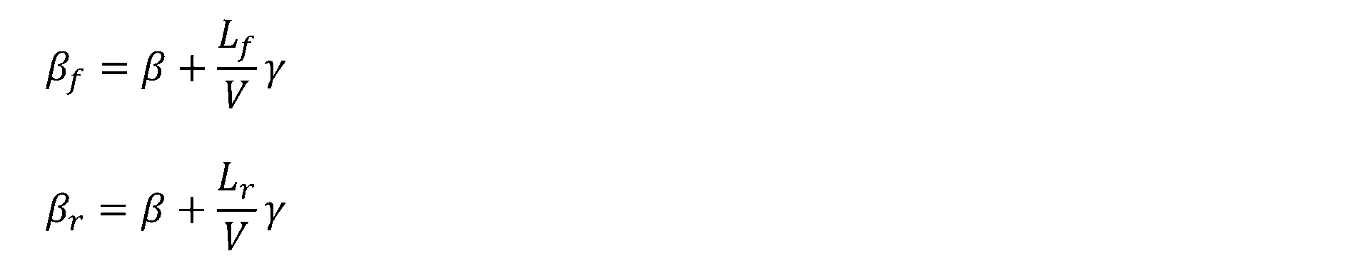
ここで、ヨーレイトγは、前輪横滑り角βf、後輪横滑り角βrを用いて表すと数式4になり、車体横滑り角βは、前輪横滑り角βf、後輪横滑り角βrを用いて表すと数式5になる。


そして、数式4、数式5をそれぞれ微分すると、数式6、数式7となる。


また、車両の運動方程式から、数式8が成立する。なお、数式8において、Izは慣性モーメントである。

そして、2自由度運動を前輪横滑り角βf、後輪横滑り角βrで表現する運動方程式は、前輪操舵角をδ、後輪操舵角をδrとし、前後輪のコーナリング係数をCf、Crとしたときに、数式9となる。

数式7に示したように、車体横滑り角速度Δβは、前輪横滑り角速度Δβf及び後輪横滑り角速度Δβrに応じて変化する。
また、数式9に示したように、前輪横滑り角速度Δβf及び後輪横滑り角速度Δβrは、前輪操舵角δ、後輪操舵角δr、及び車速Vによって変わる。
As shown in Equation 7, the vehicle body slip angular velocity Δβ changes according to the front wheel slip angular velocity Δβf and the rear wheel slip angular velocity Δβr.
As shown in Equation 9, the front wheel slip angular velocity Δβf and the rear wheel slip angular velocity Δβr vary depending on the front wheel steering angle δ, the rear wheel steering angle δr, and the vehicle speed V.
したがって、車両制御装置500は、前輪操舵角δ、後輪操舵角δr、車速Vを制御することで、過渡状態における車体横滑り角速度Δβを制御でき、さらに、目標操舵角速度、目標加減速度を制御することで、目標車体横滑り角β_tgに向けて車体横滑り角βが変化するときの目標車体横滑り角速度Δβ_tgを所定の時間変化率に制御することができる。
そして、車両制御装置500が、車両100の走行の過渡状態における目標車体横滑り角速度Δβ_tgを所定の時間変化率に制御することで、過渡状態において車両挙動の変動が発生することを抑止し、車両100の接地感、安定感が向上する。
Therefore, by controlling the front wheel steering angle δ, the rear wheel steering angle δr, and the vehicle speed V, the
Furthermore, the
以下では、車両制御装置500(詳細には、マイクロコンピュータ510)が実行する、車体横滑り角速度Δβの制御のプロセスを説明する。
図4は、車両制御装置500が、過渡状態において目標車体横滑り角速度Δβ_tgが一定になるように、前後輪の目標操舵角速度を制御するときの制御プロセスを示すフローチャートである。
The process of controlling the vehicle body sideslip angular velocity Δβ executed by the vehicle control device 500 (specifically, the microcomputer 510) will be described below.
FIG. 4 is a flowchart showing a control process when the
車両制御装置500は、ステップS21で、車両100の経路情報から、前方注視位置での目標車速、道路曲率、前方注視位置までの距離、時間の情報を取得する。
次いで、車両制御装置500は、ステップS22で、車両100の前方注視位置、つまり、最大曲率の位置での目標車速、曲率、前方注視位置までの時間から、前方注視位置での横加速度αyを目標横加速度αy_tgとして算出する。
また、車両制御装置500は、ステップS22で、前方注視位置での車体横滑り角βである目標車体横滑り角β_tgを、目標横加速度αy_tgと目標車速に基づき算出する。
In step S21, the
Next, in step S22, the
In addition, in step S22, the
なお、車両制御装置500は、車両100の前方の道路形状の情報を取得できる場合、前方のカーブの最大曲率位置を特定し、最大曲率の情報から目標横加速度αy_tg及び目標車体横滑り角β_tgを求める。
最大曲率位置は、車両100が緩和区間を経て円弧区間を走行する場合、緩和区間の終点であって、最大曲率は円弧区間の曲率である。
また、車両制御装置500は、車両100がカーブの出口に向けて走行している場合、換言すれば、車両100が直線区間手前の緩和区間を走行している場合、目標車体横滑り角β_tg及び目標横加速度αy_tgをゼロとする。
When the
When the
In addition, when the
さらに、車両制御装置500は、ステップS23で、現時点での車体横滑り角速度Δβを、車速Vの検出値、及び、横加速度αyの検出値(換言すれば、現時点での横加速度αy_ac)に基づいて算出する。
そして、車両制御装置500は、ステップS24で、車両100の過渡状態を判断する第1条件として、目標横加速度αy_tgと現時点での横加速度αy_acとの差Dαyの絶対値が所定値THαy(THαy>0)以上であるか否かを判断する。
Furthermore, in step S23, the
Then, in step S24, the
ここで、差Dαyが所定値THαy以上であって、前方注視位置に向けた過渡状態が予測される場合、車両制御装置500は、ステップS25以降に進む。
一方、差Dαyが所定値THαy以上であるという過渡判定の第1条件が成立していない場合、車両制御装置500は、車体横滑り角速度Δβの制御を実施することなく、本ルーチンを終了させる。
Here, if the difference Dαy is equal to or greater than the predetermined value THαy and a transient state toward a forward gaze position is predicted, the
On the other hand, if the first condition for transient determination, that is, the difference Dαy is equal to or greater than the predetermined value THαy, is not satisfied, the
車両制御装置500は、ステップS25で、現時点の車体横滑り角β(換言すれば、初期車体横滑り角β_in)から目標車体横滑り角β_tgにまで、目標車体横滑り角速度Δβ_tgで車体横滑り角βを変化させるための目標操舵角速度Δδ_tgを求める。
ここで、車両制御装置500は、目標車体横滑り角速度Δβ_tgを過渡状態で一定値とする場合、現時点の操舵角から目標車体横滑り角β_tgのときの目標操舵角にまで一定角速度で変化させる目標操舵角速度Δδ_tgを算出する。
換言すれば、車両制御装置500は、過渡状態での目標操舵角速度Δδ_tgを一定値に設定することで、過渡状態での目標車体横滑り角速度Δβ_tgを一定値とする。
In step S25, the
Here, when the target vehicle body slip angle velocity Δβ_tg is set to a constant value in a transient state, the
In other words, the
次いで、車両制御装置500は、ステップS26で、車両100の過渡状態を判断する第2条件として、現時点での車体横滑り角速度Δβが所定値以下であるか否か、たとえば、現時点での車体横滑り角速度Δβがゼロであるか否かを判断する。
つまり、車両制御装置500は、ステップS26で、車体横滑り角βが変化している状態であるか、車体横滑り角βが一定値を維持する状態であるかを判断する。
ここで、車体横滑り角速度Δβがゼロでなく、車両100の走行が、車体横滑り角βが変化する過渡状態になっている場合、車両制御装置500は、ステップS27に進んで、ステップS25で求めた目標操舵角速度Δδ_tgにそって操舵角を変化させる制御を実行する。
Next, in step S26, the
That is, in step S26, the
Here, if the vehicle body slip angle velocity Δβ is not zero and the
詳細には、車両制御装置500は、ステップS27で、目標操舵角速度Δδ_tgに基づき操舵角速度ゲインを定め、前輪操舵装置601、後輪操舵装置602それぞれに操舵角速度ゲインに基づく操舵制御電流を出力する。
なお、車両制御装置500は、車体横滑り角速度Δβの制御において、前輪操舵装置601と後輪操舵装置602とのうちの前輪操舵装置601のみを制御対象とすることができる。
In detail, in step S27, the
In addition, in controlling the vehicle body sideslip angular velocity Δβ, the
上記のように、車両制御装置500は、ステップS25で目標操舵角速度Δδ_tgの算出処理を行った後に、ステップS26での車体横滑り角速度Δβの判定、換言すれば、車体横滑り角速度Δβの制御の開始判定を行う。
これにより、横加速度に関する第1条件が車体横滑り角速度Δβに関する第2条件に先行して成立した時点から、制御の開始に備えて目標操舵角速度Δδ_tgの算出処理が繰り返されることになり、制御開始が判定されたときの制御量の演算周期遅れが防がれる。
As described above, after performing the process of calculating the target steering angular velocity Δδ_tg in step S25, the
As a result, from the point in time when the first condition related to the lateral acceleration is satisfied prior to the second condition related to the vehicle body sideslip angular velocity Δβ, the calculation process of the target steering angular velocity Δδ_tg is repeated in preparation for the start of control, thereby preventing a delay in the calculation cycle of the control amount when it is determined that control should be started.
一方、車体横滑り角速度Δβがゼロであって車両100の走行が定常状態である場合、車両制御装置500は、車体横滑り角速度Δβの制御を実施することなく、本ルーチンを終了させる。
つまり、車両100の前方に過渡領域が存在するものの、車両100が過渡領域に入っていない場合、たとえば、車両100が緩和区間手前の直線区間を走行している場合、車両制御装置500は、過渡状態になるまでの間、目標操舵角速度Δδ_tgの算出処理を繰り返して待機する。
以上のように、車両制御装置500は、図4のフローチャートに示したプロセスを実施することで、緩和区間での走行などの過渡状態で、一定の目標操舵角速度Δδ_tgに沿って操舵角を変化させ、過渡状態での車体横滑り角速度Δβの変動を抑止する。
On the other hand, when the vehicle body skid angular velocity Δβ is zero and the
In other words, if a transitional region exists ahead of the
As described above, the
図5は、車両制御装置500が、車両制御装置500が、過渡状態において車体横滑り角速度Δβが一定になるように、車両100の目標加減速度を制御するときの制御プロセスを示すフローチャートである。
図5のフローチャートのステップS31からステップS34までの各ステップでは、図4のフローチャートのステップS21からステップS24までの各ステップと同様な処理が実施されるので、ここでの詳細な説明は省略する。
FIG. 5 is a flowchart showing a control process when the
In steps S31 to S34 in the flowchart of FIG. 5, the same processes as in steps S21 to S24 in the flowchart of FIG. 4 are carried out, and therefore detailed description thereof will be omitted here.
車両制御装置500は、ステップS34において差Dαyが所定値THαy以上であると判断すると、ステップS35に進む。
そして、車両制御装置500は、ステップS35で、現時点の車体横滑り角β(換言すれば、初期車体横滑り角β_in)から目標車体横滑り角β_tgにまで、目標車体横滑り角速度Δβ_tgで車体横滑り角βを変化させるための目標加減速度AD_tgを求める。
When the
Then, in step S35, the
ここで、車両制御装置500は、目標車体横滑り角速度Δβ_tgを過渡状態で一定値とする場合、現時点の車速から目標車体横滑り角β_tgのときの目標車速にまで一定の加減速度で変化させる目標加減速度AD_tgを算出する。
換言すれば、車両制御装置500は、過渡状態での目標加減速度AD_tgを一定値に設定することで、過渡状態での目標車体横滑り角速度Δβ_tgを一定値とする。
Here, when the target vehicle body slip angle velocity Δβ_tg is set to a constant value in a transient state, the
In other words, the
次いで、車両制御装置500は、ステップS36で、ステップS26と同様に、現時点での車体横滑り角速度Δβがゼロであるか否かを判断する。
そして、車両制御装置500は、ステップS36で、現時点での車体横滑り角速度Δβがゼロでないと判断すると、ステップS37に進む。
Next, in step S36, the
Then, when the
車両制御装置500は、ステップS37で、ステップS35で求めた目標加減速度AD_tgにそって車速を変化させる制御を実行する。
詳細には、車両制御装置500は、ステップS37で、目標加減速度AD_tgに基づき回転速度ゲインを定める。
そして、車両制御装置500は、加速時であれば、駆動装置603に回転速度ゲインに基づく駆動制御電流を出力し、減速時であれば、制動装置604に回転速度ゲインに基づく制動制御電流を出力する。
以上のように、車両制御装置500は、図5のフローチャートに示したプロセスを実施することで、緩和区間での走行などの過渡状態で、一定の目標加減速度AD_tgに沿って車速(車輪速)を変化させ、過渡状態での車体横滑り角速度Δβの変動を抑止する。
In step S37, the
Specifically, in step S37, the
During acceleration, the
As described above, the
図6は、車両制御装置500が、車両制御装置500が、過渡状態において車体横滑り角速度Δβが一定になるように、目標操舵角速度と目標加減速度との両方を制御するときの制御プロセスを示すフローチャートである。
図6のフローチャートのステップS41からステップS44までの各ステップでは、図4のフローチャートのステップS21からステップS24までの各ステップと同様な処理が実施されるので、ここでの詳細な説明は省略する。
FIG. 6 is a flowchart showing a control process when the
In steps S41 to S44 in the flowchart of FIG. 6, the same processes as those in steps S21 to S24 in the flowchart of FIG. 4 are carried out, and therefore detailed description thereof will be omitted here.
車両制御装置500は、ステップS44において差Dαyが所定値THαy以上であると判断すると、ステップS45の処理とステップS46の処理とを並行して実施する。
車両制御装置500は、ステップS45では、ステップS25と同様にして目標操舵角速度Δδ_tgを求め、ステップS46では、ステップS35と同様にして目標加減速度AD_tgを求める。
When the
In step S45, the
次いで、車両制御装置500は、ステップS47で、ステップS26と同様に、現時点での車体横滑り角速度Δβがゼロであるか否かを判断する。
そして、車両制御装置500は、ステップS47で、現時点での車体横滑り角速度Δβがゼロでないと判断すると、ステップS48に進む。
Next, in step S47, the
If the
車両制御装置500は、ステップS48で、ステップS27と同様に、目標操舵角速度Δδ_tgに基づき操舵角速度ゲインを定め、前輪操舵装置601、後輪操舵装置602それぞれに操舵角速度ゲインに基づく操舵制御電流を出力する。
さらに、車両制御装置500は、ステップS48で、ステップS37と同様に、目標加減速度AD_tgに基づき回転速度ゲインを定め、加速時であれば、駆動装置603に回転速度ゲインに基づく駆動制御電流を出力し、減速時であれば、制動装置604に回転速度ゲインに基づく制動制御電流を出力する。
以上のように、車両制御装置500は、図6のフローチャートに示したプロセスを実施することで、緩和区間での走行などの過渡状態で、一定の目標操舵角速度Δδ_tgに基づき操舵角を変化させ、かつ、一定の目標加減速度AD_tgに沿って車速(車輪速)を変化させ、過渡状態での車体横滑り角速度Δβの変動を抑止する。
In step S48, similar to step S27, the
Furthermore, in step S48, as in step S37, the
As described above, the
図7のタイムチャートは、車両100が、直線区間→緩和区間→円弧区間→緩和区間→直線区間のカーブ路を走行するときの、前輪操舵角、車輪回転速度、車体横滑り角β、横加速度、前後加速度の変化を例示する。
なお、図7の実線は、車両制御装置500が車体横滑り角速度Δβの制御(詳細には、目標操舵角速度及び目標加減速度を一定とする制御)を実施した状態を示し、図7の点線は、車体横滑り角速度Δβの制御を実施しない状態を示す。
The time chart in Figure 7 illustrates changes in front wheel steering angle, wheel rotational speed, vehicle body sideslip angle β, lateral acceleration, and longitudinal acceleration when
Note that the solid line in Figure 7 indicates a state in which the
車体横滑り角速度Δβの制御が実施されない場合は、車両100が緩和区間を走行する過渡状態において、操舵角速度や加減速度の変化に伴って車体横滑り角βが不安定に動き、車両100の接地感、安定感を低下させる。
これに対し、車体横滑り角速度Δβの制御が実施される場合は、過渡状態で目標操舵角速度及び目標加減速度(換言すれば、目標前後加速度)が一定に制御されることで、車体横滑り角βが一定の角速度Δβで変化し、過渡状態における車両100の接地感、安定感が向上する。
If control of the vehicle body slip angle velocity Δβ is not performed, the vehicle body slip angle β will move unstably in accordance with changes in the steering angular velocity and acceleration/deceleration during the transitional state in which the
In contrast, when control of the vehicle body slip angular velocity Δβ is implemented, the target steering angular velocity and target acceleration/deceleration (in other words, the target longitudinal acceleration) are controlled to be constant in the transient state, so that the vehicle body slip angle β changes at a constant angular velocity Δβ, improving the sense of contact and stability of the
ところで、車両制御装置500は、目標車体横滑り角速度Δβ_tgが所定の時間変化率になるような車両100の目標位置に基づいて車両100の目標軌道を生成することができる。
つまり、車両制御装置500は、目標車体横滑り角速度Δβ_tgが所定の時間変化率になるような目標操舵角速度Δδ_tg、または、目標加減速度AD_tgを組み込んだ目標軌道を生成し、係る目標軌道をトレースするようにアクチュエータ部600を制御することができる。
Incidentally, the
In other words, the
図8は、車体横滑り角速度Δβの制御として目標軌道の生成を実施する車両制御装置500を示すブロック図である。
図8に示す車両制御装置500は、図1に示した車両制御装置500が備えるβ角速度要求値算出部513に代えて、目標位置換算部516を有する。
目標位置換算部516は、車体横滑り角速度Δβ_tgを組み込んだ目標車両位置を求める機能部である。
FIG. 8 is a block diagram showing a
The
The target
図9は、目標位置換算部516における信号伝達経路を詳細に示すブロック線図である。
また、図10は、前方注視位置での車両100の目標軌道からの横ずれ量εをワールド座標系で示す図である。
ここで、横ずれ量εは、下式にしたがって求められる。
ε=y+Lφ-yOL
FIG. 9 is a block diagram showing in detail the signal transmission path in the target
FIG. 10 is a diagram showing, in the world coordinate system, the lateral deviation ε of the
Here, the lateral deviation ε is calculated according to the following formula:
ε=y+Lφ- yOL
そして、目標位置換算部516は、横ずれ量εを舵角δに換算し、車体横滑り角β、ヨーレイトγを数式10、数式11にしたがって求める。


さらに、目標位置換算部516は、車体横滑り角β、ヨーレイトγから、数式12、数式13にしたがって、前方向車両速度、横方向車両速度を求める。


そして、目標位置換算部516は、目標車体横滑り角速度Δβ_tgを付加して、目標車両位置を表す前方向車両位置x及び横方向車両位置yを、数式14、数式15にしたがって求め、この目標車両位置の情報(詳細には、前方向車両位置x及び横方向車両位置y)を目標軌道に関する情報として、制御量算出部515に出力する。
制御量算出部515は、取得した目標車両位置を通過するように、アクチュエータ部600を制御する。


The control
図11は、目標車体横滑り角速度Δβ_tgを加味して目標軌道を計画する場合の制御プロセスを示すフローチャートである。
図11のフローチャートのステップS51からステップS54までの各ステップでは、図4のフローチャートのステップS21からステップS24までの各ステップと同様な処理が実施されるので、ここでの詳細な説明は省略する。
FIG. 11 is a flowchart showing a control process when a target trajectory is planned taking into account the target vehicle body slip angular velocity Δβ_tg.
In steps S51 to S54 in the flowchart of FIG. 11, the same processes as in steps S21 to S24 in the flowchart of FIG. 4 are carried out, and therefore detailed description thereof will be omitted here.
車両制御装置500は、ステップS54において差Dαyが所定値THαy以上であると判断すると、ステップS55に進む。
車両制御装置500は、ステップS55で、目標車体横滑り角速度Δβ_tgを組み込んだ目標車両位置を算出する。
係る目標車両位置は、前述したように、図8に示した目標位置換算部516によって数式14、数式15にしたがい求められる。
When the
In step S55, the
As described above, the target vehicle position is calculated by the target
次いで、車両制御装置500は、ステップS56で、目標車体横滑り角速度Δβ_tgを組み込んだ目標車両位置に車両100を追従させるための各デバイスの目標値となる制御量を算出する。
そして、車両制御装置500は、ステップS57で、現時点での車体横滑り角速度Δβがゼロであるか否かを判断することで、車両100が、過渡状態になっているか否かを判断する。
ここで、現時点での車体横滑り角速度Δβがゼロでない場合、車両制御装置500は、ステップS58に進み、ステップS56で求めた制御量に基づき、制駆動力を制御し、また、前後輪の操舵角を制御することで、目標車体横滑り角速度Δβ_tgを組み込んだ目標車両位置に車両100を追従させる。
Next, in step S56, the
Then, in step S57, the
Here, if the current vehicle body skid angular velocity Δβ is not zero, the
このように、車両制御装置500は、目標車体横滑り角速度Δβ_tgを組み込んだ軌道を計画することによって、換言すれば、目標車体横滑り角速度Δβ_tgを実現できるように目標軌道を修正することで、たとえば、目標車体横滑り角速度Δβ_tgが一定となる過渡走行を実現でき、車両走行の過渡状態における車両100の接地感、安定感を向上させることができる。
なお、目標車体横滑り角速度Δβ_tgを一定値とする場合、目標車体横滑り角速度Δβ_tgを組み込んだ目標軌道は、過渡領域で目標操舵角速度及び目標加減速度が一定となる目標軌道となる。
In this way, by planning a trajectory that incorporates the target vehicle body slip angular velocity Δβ_tg, in other words, by correcting the target trajectory so as to realize the target vehicle body slip angular velocity Δβ_tg, the
When the target vehicle body sideslip angular velocity Δβ_tg is set to a constant value, the target trajectory incorporating the target vehicle body sideslip angular velocity Δβ_tg becomes a target trajectory in which the target steering angular velocity and the target acceleration/deceleration are constant in the transition region.
ところで、車両制御装置500が実施する車体横滑り角速度Δβの制御は、過渡状態における目標車体横滑り角速度Δβ_tgを一定値とする制御、つまり、過渡状態における目標車体横滑り角加速度ΔΔβ_tgをゼロとする制御に限定されない。
図12は、過渡状態において一定値ではない目標車体横滑り角速度Δβ_tgの一例を示すタイムチャートである。
Incidentally, the control of the vehicle body slip angular velocity Δβ performed by the
FIG. 12 is a time chart showing an example of target vehicle body slip angular velocity Δβ_tg that is not a constant value in a transient state.
図12に示す例では、目標車体横滑り角速度Δβ_tgは、過渡領域の当初、詳細には、車両100が直進区間から緩和区間に進入した当初、及び、円弧区間から緩和区間に進入した当初において、車体横滑り角βが、車体が旋回外向きとなる側に一定角速度で変化するように設定される。
その後、目標車体横滑り角速度Δβ_tgは、車体横滑り角βが、ある角度で変化方向が反転してゼロに戻り、車体が旋回内向きとなる側で、最大曲率での車体横滑り角βに向けて一定角速度で変化するように設定される。
In the example shown in FIG. 12 , the target vehicle body slip angle velocity Δβ_tg is set so that at the beginning of the transition region, specifically, when the
Thereafter, the target vehicle body slip angle velocity Δβ_tg is set so that the direction of change of the vehicle body slip angle β reverses at a certain angle and returns to zero, and the target vehicle body slip angle Δβ changes at a constant angular velocity toward the vehicle body slip angle β at maximum curvature on the side where the vehicle body faces inward during turning.
つまり、図12に示す例では、目標車体横滑り角速度Δβ_tgは、過渡領域の当初において、前方注視位置での車体横滑り角βに向かう方向とは逆方向に設定され、その後、前方注視位置での車体横滑り角βに向かう方向に反転する。
車体横滑り角βを、車両100が過渡領域に進入した時点から前方注視位置での車体横滑り角βに向けて変化させる場合よりも、一旦、車体横滑り角βを車体が旋回外向きとなる側に変化させてから、前方注視位置での車体横滑り角βに向けて変化させる方が、車両100の接地感をより高めることができる。
In other words, in the example shown in FIG. 12, the target vehicle body slip angle velocity Δβ_tg is set in the opposite direction to the vehicle body slip angle β at the forward gaze position at the beginning of the transition region, and then reverses to the direction toward the vehicle body slip angle β at the forward gaze position.
The sense of contact of
なお、車両100が直進区間から緩和区間に進入した当初は、図12に点線で示したように、車体横滑り角速度Δβの制御を実施しない場合でも、車体横滑り角βは車体が旋回外向きとなる側に一時的に変化する。
ここで、車両100が直進区間から緩和区間に進入した当初における目標車体横滑り角速度Δβ_tgは、車体が旋回外向きとなる側での車体横滑り角βの大きさが、車体横滑り角速度Δβの制御を実施しない場合よりも大きくならないように設定され、さらに、車体横滑り角βがゼロに戻ってからは、最大曲率での車体横滑り角βに向けて一定角度で変化させるように設定される。
係る目標車体横滑り角速度Δβ_tgの設定によって、過渡状態での車体横滑り角βの変化を制御することで、車両の接地感、安定感をより一層向上させることができる。
Incidentally, when the
Here, the target vehicle body slip angle velocity Δβ_tg when the
By controlling the change in the vehicle body slip angle β in a transient state through setting the target vehicle body slip angle velocity Δβ_tg in this manner, the feeling of contact with the ground and stability of the vehicle can be further improved.
なお、車両制御装置500は、過渡当初において逆方向へ車体横滑り角βを変化させるときの目標車体横滑り角速度Δβ_tgや目標期間などを、曲率の変化率や車速などに応じて可変設定することができる。
また、車体横滑り角βをゼロから最大曲率での車体横滑り角βに向けて変化させるときの目標車体横滑り角速度Δβ_tgは一定値に限定されず、所定範囲内での角速度の変化は許容される。
The
Furthermore, the target vehicle body slip angle velocity Δβ_tg when the vehicle body slip angle β is changed from zero toward the vehicle body slip angle β at the maximum curvature is not limited to a constant value, and changes in the angular velocity within a predetermined range are permitted.
車両制御装置500は、車体が旋回外向きとなる側へ車体横滑り角βを変化させるときに、前後加速度を下げる制御や、後輪103,104を逆位相に操舵する制御を実施することで、車体が旋回外向きとなる側での車体横滑り角βの変化を制御することができる。
また、マイクロコンピュータ510は、左右輪の間での制駆動力の差を制御することで、車両100に発生する回頭モーメントを制御し、車体が旋回外向きとなる側での車体横滑り角βの変化を制御することができる。
When changing the vehicle body slip angle β to the side where the vehicle body will turn outward, the
In addition, the
図13は、車両制御装置500が、過渡状態における目標車体横滑り角速度Δβ_tgが、図12に例示したような所定の時間変化率になるように、前後輪の目標操舵角速度や目標加減速度などを制御するときの制御プロセスを示すフローチャートである。
図13のフローチャートのステップS61からステップS64までの各ステップでは、図4のフローチャートのステップS21からステップS24までの各ステップと同様な処理が実施されるので、ここでの詳細な説明は省略する。
FIG. 13 is a flowchart showing a control process when the
In steps S61 to S64 in the flowchart of FIG. 13, the same processes as in steps S21 to S24 in the flowchart of FIG. 4 are carried out, and therefore detailed description thereof will be omitted here.
車両制御装置500は、ステップS64で、目標横加速度αy_tgと現時点での横加速度αy_acとの差が所定以上であるという過渡判定条件が成立していると判断すると、ステップS65での処理とステップS66での処理とを並行して実行する。
車両制御装置500は、ステップS65で、目標車体横滑り角速度Δβ_tgがたとえば図12に例示したような所定の時間変化率になるように、前方注視位置に向けての目標操舵角速度Δδ_tgを時系列に算出する。
ここで、図12に示した例では、過渡当初に後輪103,104の操舵角を逆位相とするような目標操舵角速度Δδ_tgが算出される。
When the
In step S65, the
In the example shown in FIG. 12, a target steering angular velocity Δδ_tg is calculated that makes the steering angles of the
また、車両制御装置500は、ステップS66で、目標車体横滑り角速度Δβ_tgがたとえば図12に例示したような所定の時間変化率になるように、前方注視位置に向けての目標加減速度AD_tgを時系列に算出する。
なお、車両制御装置500は、前述したように、過渡当初において車体が旋回外向きとなる側へ車体横滑り角βを変化させるために、左輪と右輪との間における制駆動力差の制御や電子制御式LSDの制御で回頭モーメントを発生させることができる。
In addition, in step S66, the
As described above, the
車両制御装置500は、目標操舵角速度Δδ_tg、目標加減速度AD_tgを算出すると、ステップS67に進み、現時点での車体横滑り角速度Δβがゼロであるか否かを判断する。
ここで、車体横滑り角速度Δβがゼロでなく、車両100の走行が過渡状態になっている場合、車両制御装置500は、ステップS68に進んで、車体横滑り角速度Δβの制御を実行する。
After calculating the target steering angular velocity Δδ_tg and the target acceleration/deceleration AD_tg, the
Here, if the vehicle body skid angular velocity Δβ is not zero and the
車両制御装置500は、ステップS68で、そのときの目標加減速度AD_tgに基づき車輪の回転速度ゲインを定め、駆動装置603、制動装置604それぞれに制駆動制御電流を出力し、また、そのときの目標操舵角速度Δδ_tgに基づき操舵角速度ゲインを定め、前輪操舵装置601、後輪操舵装置602それぞれに操舵制御電流を出力する。
一方、車体横滑り角速度Δβがゼロであって車両100の走行が定常状態である場合、つまり、過渡状態になる前の定常状態である場合、車両制御装置500は、車体横滑り角速度Δβの制御を実施することなく、本ルーチンを終了させる。
上記のように、車両制御装置500は、目標車体横滑り角速度Δβ_tgが一定値ではない所定の時間変化率となるように目標操舵角速度や目標加減速度を制御することで、一定値とする場合よりもさらに車両の接地感、安定感を向上させることが可能になる。
In step S68, the
On the other hand, if the vehicle body skid angular velocity Δβ is zero and the
As described above, the
上記実施形態で説明した各技術的思想は、矛盾が生じない限りにおいて、適宜組み合わせて使用することができる。
また、好ましい実施形態を参照して本発明の内容を具体的に説明したが、本発明の基本的技術思想及び教示に基づいて、当業者であれば、種々の変形態様を採り得ることは自明である。
The technical ideas described in the above embodiments can be used in any suitable combination as long as no contradiction occurs.
Furthermore, although the contents of the present invention have been specifically described with reference to preferred embodiments, it is obvious that a person skilled in the art can adopt various modified embodiments based on the basic technical concept and teachings of the present invention.
たとえば、車両制御装置500は、車速Vが所定速度(たとえば、所定速度=40km/h)を超えていることを、車体横滑り角速度Δβの制御の実施条件として付加することができる。
上記の車速Vの条件は、車体横滑り角速度Δβの制御を、接地感、安定感の向上に寄与できる中高車速域で実施させるためのものであり、車速Vの条件を付加することで、低車速域で実効性のない制御が無用に実施されることを抑止できる。
For example, the
The above condition for vehicle speed V is intended to perform control of vehicle body skid angular velocity Δβ at medium to high vehicle speeds that can contribute to improving the feeling of contact with the ground and stability. Adding the condition for vehicle speed V makes it possible to prevent ineffective control from being unnecessarily performed at low vehicle speeds.
車両100が、駆動装置603として内燃機関を備える場合、車両制御装置500は、目標加減速度に応じてスロットル開度を制御することができる。
また、車両100は、車両100が直線区間から緩和区間に入ったときと、円弧区間から緩和区間に入ったときとのいずれか一方で、車体横滑り角速度Δβの制御を実施することができる。
When the
Furthermore, the
100…車両、500…車両制御装置、510…マイクロコンピュータ(コントロール部)、513…β角速度要求値算出部、514…過渡領域検知部、515…制御量算出部、600…アクチュエータ部、601…前輪操舵装置、602…後輪操舵装置、603…駆動装置、604…制動装置 100...vehicle, 500...vehicle control device, 510...microcomputer (control unit), 513...β angular velocity requirement value calculation unit, 514...transient region detection unit, 515...control amount calculation unit, 600...actuator unit, 601...front wheel steering device, 602...rear wheel steering device, 603...drive device, 604...braking device
Claims (10)
前記車両制御装置が備えるコントロール部は、
車両の走行が過渡状態から定常状態へ遷移するときの前記過渡状態における目標車体横滑り角速度が所定の時間変化率になるように、前記車両の目標操舵角速度、または目標加減速度のうち少なくとも一方を制御する、
車両制御装置。 A vehicle control device,
The control unit of the vehicle control device includes:
controlling at least one of a target steering angular velocity and a target acceleration/deceleration of the vehicle so that a target vehicle body sideslip angular velocity in a transition state when the traveling of the vehicle transitions from a transition state to a steady state has a predetermined time change rate;
Vehicle control device.
前記所定の時間変化率はゼロである、
車両制御装置。 The vehicle control device according to claim 1,
the predetermined time rate of change is zero;
Vehicle control device.
前記コントロール部は、
前記目標操舵角速度を一定、または前記目標加減速度を一定に制御する、
車両制御装置。 The vehicle control device according to claim 2,
The control unit includes:
Controlling the target steering angular velocity to a constant value or the target acceleration/deceleration to a constant value.
Vehicle control device.
前記コントロール部は、
前記過渡状態の初期の前記車両の走行を示す第1走行状態での前記車両の速度と前記車両の横加速度に基づいて、初期車体横滑り角を取得し、
前記第1走行状態から前記車両の走行が前記定常状態に遷移する第2走行状態での前記車両の目標速度と前記車両の目標横加速度に基づいて、目標車体横滑り角を取得し、
前記初期車体横滑り角と前記目標車体横滑り角に基づいて前記目標車体横滑り角速度を求める、
車両制御装置。 The vehicle control device according to claim 3,
The control unit includes:
obtaining an initial vehicle body sideslip angle based on a speed of the vehicle and a lateral acceleration of the vehicle in a first running state indicating running of the vehicle at an initial stage of the transient state;
acquiring a target vehicle body sideslip angle based on a target speed of the vehicle and a target lateral acceleration of the vehicle in a second running state in which the running of the vehicle transitions from the first running state to the steady state;
determining the target vehicle body sideslip angular velocity based on the initial vehicle body sideslip angle and the target vehicle body sideslip angle;
Vehicle control device.
前記第1走行状態は、前記車両が旋回を開始するときの状態であり、
前記第2走行状態は、前記車両が旋回を開始した後に、定常旋回になるときの状態である、
車両制御装置。 The vehicle control device according to claim 4,
the first running state is a state when the vehicle starts turning,
The second running state is a state in which the vehicle starts turning and then turns steadily.
Vehicle control device.
前記第1走行状態は、前記車両が定常旋回を終了した後、前記車両の操舵角を増減または加減速を開始するときの状態であり、
前記第2走行状態は、前記車両が定常旋回を終了した後、前記車両が直進する状態である、
車両制御装置。 The vehicle control device according to claim 4,
The first traveling state is a state in which the steering angle of the vehicle starts to be increased or decreased or the vehicle starts to be accelerated or decelerated after the vehicle has finished a steady turn,
The second running state is a state in which the vehicle travels straight after the vehicle has completed a steady turn.
Vehicle control device.
前記コントロール部は、
車体横滑り角速度がゼロでなく、かつ、前記目標横加速度と前記横加速度に差がある場合に、前記制御を実行する、
車両制御装置。 The vehicle control device according to claim 4,
The control unit includes:
executing the control when a vehicle body sideslip angular velocity is not zero and there is a difference between the target lateral acceleration and the lateral acceleration;
Vehicle control device.
前記コントロール部は、
前記目標操舵角速度及び前記目標加減速度の両方を制御する、
車両制御装置。 The vehicle control device according to claim 1,
The control unit includes:
controlling both the target steering angular velocity and the target acceleration/deceleration;
Vehicle control device.
前記コントロール部は、
前記目標車体横滑り角速度が所定の時間変化率になるような前記車両の目標位置に基づいて前記車両の目標軌道を生成する、
車両制御装置。 The vehicle control device according to claim 1,
The control unit includes:
generating a target trajectory of the vehicle based on a target position of the vehicle such that the target vehicle body sideslip angular velocity has a predetermined time change rate;
Vehicle control device.
前記コントロール部は、
前記車両が旋回を開始してから定常旋回になるまでの区間において、前記車両の目標操舵角速度及び目標加減速度を一定に制御する、
車両制御方法。 A vehicle control method executed by a control unit provided in a vehicle, comprising:
The control unit includes:
A target steering angular velocity and a target acceleration/deceleration of the vehicle are controlled to be constant during a period from when the vehicle starts turning until when the vehicle reaches a steady turning state.
A vehicle control method.
Priority Applications (3)
| Application Number | Priority Date | Filing Date | Title |
|---|---|---|---|
| JP2025525942A JPWO2024252717A1 (en) | 2023-06-08 | 2024-01-18 | |
| DE112024002462.9T DE112024002462T5 (en) | 2023-06-08 | 2024-01-18 | VEHICLE CONTROL DEVICE AND VEHICLE CONTROL METHOD |
| CN202480018772.XA CN120826342A (en) | 2023-06-08 | 2024-01-18 | Vehicle control device and vehicle control method |
Applications Claiming Priority (2)
| Application Number | Priority Date | Filing Date | Title |
|---|---|---|---|
| JP2023094586 | 2023-06-08 | ||
| JP2023-094586 | 2023-06-08 |
Publications (1)
| Publication Number | Publication Date |
|---|---|
| WO2024252717A1 true WO2024252717A1 (en) | 2024-12-12 |
Family
ID=93795818
Family Applications (1)
| Application Number | Title | Priority Date | Filing Date |
|---|---|---|---|
| PCT/JP2024/001239 Ceased WO2024252717A1 (en) | 2023-06-08 | 2024-01-18 | Vehicle control device and vehicle control method |
Country Status (4)
| Country | Link |
|---|---|
| JP (1) | JPWO2024252717A1 (en) |
| CN (1) | CN120826342A (en) |
| DE (1) | DE112024002462T5 (en) |
| WO (1) | WO2024252717A1 (en) |
Citations (3)
| Publication number | Priority date | Publication date | Assignee | Title |
|---|---|---|---|---|
| JP2007001365A (en) * | 2005-06-22 | 2007-01-11 | Toyota Motor Corp | Vehicle steering control device |
| WO2017183486A1 (en) * | 2016-04-18 | 2017-10-26 | 日立オートモティブシステムズ株式会社 | Travel control device |
| JP2020125057A (en) * | 2019-02-06 | 2020-08-20 | 日産自動車株式会社 | Wheel load control method and wheel load control device of vehicle |
Family Cites Families (1)
| Publication number | Priority date | Publication date | Assignee | Title |
|---|---|---|---|---|
| JP4468509B2 (en) | 1999-04-06 | 2010-05-26 | 本田技研工業株式会社 | Vehicle steering system |
-
2024
- 2024-01-18 JP JP2025525942A patent/JPWO2024252717A1/ja active Pending
- 2024-01-18 WO PCT/JP2024/001239 patent/WO2024252717A1/en not_active Ceased
- 2024-01-18 CN CN202480018772.XA patent/CN120826342A/en active Pending
- 2024-01-18 DE DE112024002462.9T patent/DE112024002462T5/en active Pending
Patent Citations (3)
| Publication number | Priority date | Publication date | Assignee | Title |
|---|---|---|---|---|
| JP2007001365A (en) * | 2005-06-22 | 2007-01-11 | Toyota Motor Corp | Vehicle steering control device |
| WO2017183486A1 (en) * | 2016-04-18 | 2017-10-26 | 日立オートモティブシステムズ株式会社 | Travel control device |
| JP2020125057A (en) * | 2019-02-06 | 2020-08-20 | 日産自動車株式会社 | Wheel load control method and wheel load control device of vehicle |
Also Published As
| Publication number | Publication date |
|---|---|
| CN120826342A (en) | 2025-10-21 |
| DE112024002462T5 (en) | 2026-03-26 |
| JPWO2024252717A1 (en) | 2024-12-12 |
Similar Documents
| Publication | Publication Date | Title |
|---|---|---|
| US7860653B2 (en) | Obstacle avoidance control apparatus | |
| JP6952014B2 (en) | Vehicle control device, vehicle control method, and vehicle control system | |
| JP6752875B2 (en) | Travel control device | |
| US8457868B2 (en) | Lane keeping assist device and lane keeping assist method | |
| US20150336587A1 (en) | Driving assist device | |
| EP2712780B1 (en) | Method and apparatus for performing driving assistance | |
| JP4873047B2 (en) | Travel control device | |
| JP5569631B2 (en) | Lane maintenance support method and lane maintenance support device | |
| US20170088174A1 (en) | Driving assistance control apparatus for vehicle | |
| JP2009061878A (en) | Travel control device | |
| JP7487994B2 (en) | Vehicle driving assistance device. | |
| JP5227082B2 (en) | Vehicle steering control device equipped with a four-wheel steering mechanism | |
| JP5853552B2 (en) | Vehicle travel control device | |
| US9031709B2 (en) | Vehicle travel control apparatus and vehicle travel control method | |
| US20030195684A1 (en) | System and method for using vehicle operator intent to adjust vehicle control system response | |
| WO2016110729A1 (en) | Target vehicle speed generation device and drive control device | |
| JP6986463B2 (en) | Driving support device, driving support method and driving support system | |
| JP7535648B2 (en) | VEHICLE CONTROL DEVICE, VEHICLE CONTROL METHOD, TARGET TRACK CALCULATION METHOD, AND VEHICLE | |
| JP7521701B2 (en) | Vehicle control method and vehicle control device | |
| JP2013086781A (en) | Vehicle travel support device | |
| JP5045108B2 (en) | Driving support device | |
| JP6706166B2 (en) | Vehicle running control device | |
| JP4576922B2 (en) | Vehicle travel control device | |
| JP4970134B2 (en) | Vehicle driving support device | |
| CN120826342A (en) | Vehicle control device and vehicle control method |
Legal Events
| Date | Code | Title | Description |
|---|---|---|---|
| 121 | Ep: the epo has been informed by wipo that ep was designated in this application |
Ref document number: 24818956 Country of ref document: EP Kind code of ref document: A1 |
|
| ENP | Entry into the national phase |
Ref document number: 2025525942 Country of ref document: JP Kind code of ref document: A |
|
| WWE | Wipo information: entry into national phase |
Ref document number: 2025525942 Country of ref document: JP |
|
| WWE | Wipo information: entry into national phase |
Ref document number: 202480018772.X Country of ref document: CN |
|
| WWP | Wipo information: published in national office |
Ref document number: 202480018772.X Country of ref document: CN |
|
| WWE | Wipo information: entry into national phase |
Ref document number: 112024002462 Country of ref document: DE |
|
| WWP | Wipo information: published in national office |
Ref document number: 112024002462 Country of ref document: DE |