WO2024252720A1 - Imprimante à jet d'encre et procédé de nettoyage d'unité de tête - Google Patents
Imprimante à jet d'encre et procédé de nettoyage d'unité de tête Download PDFInfo
- Publication number
- WO2024252720A1 WO2024252720A1 PCT/JP2024/002062 JP2024002062W WO2024252720A1 WO 2024252720 A1 WO2024252720 A1 WO 2024252720A1 JP 2024002062 W JP2024002062 W JP 2024002062W WO 2024252720 A1 WO2024252720 A1 WO 2024252720A1
- Authority
- WO
- WIPO (PCT)
- Prior art keywords
- wiping
- head
- ink
- blade
- wipe
- Prior art date
- Legal status (The legal status is an assumption and is not a legal conclusion. Google has not performed a legal analysis and makes no representation as to the accuracy of the status listed.)
- Ceased
Links
Images


Classifications
-
- B—PERFORMING OPERATIONS; TRANSPORTING
- B41—PRINTING; LINING MACHINES; TYPEWRITERS; STAMPS
- B41J—TYPEWRITERS; SELECTIVE PRINTING MECHANISMS, i.e. MECHANISMS PRINTING OTHERWISE THAN FROM A FORME; CORRECTION OF TYPOGRAPHICAL ERRORS
- B41J2/00—Typewriters or selective printing mechanisms characterised by the printing or marking process for which they are designed
- B41J2/005—Typewriters or selective printing mechanisms characterised by the printing or marking process for which they are designed characterised by bringing liquid or particles selectively into contact with a printing material
- B41J2/01—Ink jet
- B41J2/135—Nozzles
- B41J2/165—Prevention or detection of nozzle clogging, e.g. cleaning, capping or moistening for nozzles
Definitions
- An inkjet printer includes a treatment liquid head that ejects treatment liquid, an ink head that ejects ink, a first wiping member that wipes the nozzle arrangement surface of the treatment liquid head, and a second wiping member different from the first wiping member that wipes the nozzle arrangement surface of the ink head.
- a method for cleaning a head unit is a method for cleaning a head unit having a treatment liquid head that ejects a treatment liquid and an ink head that ejects ink, in which a nozzle arrangement surface of the treatment liquid head is wiped with a first wiping member, and a nozzle arrangement surface of the ink head is wiped with a second wiping member different from the first wiping member.
- FIG. 1 is a front view showing the overall configuration of an inkjet printer according to an embodiment of the present disclosure.
- FIG. 2 is a cross-sectional view taken along line II-II of FIG. 1 with a printing press added.
- FIG. 3 is an enlarged perspective view of the carriage shown in FIG.
- FIG. 4 is a perspective view of a blade wiping device (first wiping device) that is installed in the printer for cleaning the treatment liquid head and the ink head.
- the upper diagram in FIG. 5 is a plan view of the blade wipe unit, and the lower diagram in FIG. 5 is a plan view showing the arrangement of the heads mounted on the carriage.
- FIG. 6 is a perspective view of an ink blade provided in the blade wipe unit.
- FIG. 7 is a schematic cross-sectional view of the carriage and the blade wipe unit.
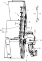
- FIG. 8 is a perspective view of a cloth wiping device (second wiping device) that is installed in a printer for cleaning the ink heads, showing the cleaning state of the nozzle arrangement surface.
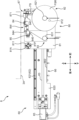
- FIG. 9A is a left side view of the cloth wiping device.
- FIG. 9B is a side view of the mobile unit.
- FIG. 10 is a perspective view of the cloth wipe unit.
- FIG. 11 is a left side view of the cloth wiping device, showing a state in which the cloth wiping unit is in the cleaning position.
- FIG. 12 is a block diagram showing a part of the control configuration of the inkjet printer.
- FIG. 13 is a flow chart showing an example of a cleaning operation for the ink head and the treatment liquid head in an ink jet printer.
- FIG. 14A is a diagram showing a procedure for cleaning an ink head using a blade wipe unit.
- FIG. 14B is a diagram showing a procedure for cleaning the ink head using the blade wipe unit.
- FIG. 14C is a diagram showing a procedure for cleaning the ink head using a blade wipe unit.
- FIG. 15 is a flow chart showing another example of the cleaning operation for the ink heads and the treatment liquid heads.
- FIG. 16 is a front view showing the overall configuration of an ink jet printer according to a modified embodiment.
- an example of an inkjet printer of the present disclosure is a printer equipped with an ink head that ejects ink for forming an image onto a wide, long recording medium.
- An example of a head unit cleaning method of the present disclosure is applied to a head unit equipped in the printer.
- the inkjet printer of this embodiment is suitable for digital textile printing, which uses an inkjet method to print images such as characters and patterns onto a recording medium (work) made of fabric such as woven or knitted fabric.
- the inkjet printer and cleaning method according to the present disclosure can also be used for printing various inkjet images onto recording media such as paper sheets and resin sheets.
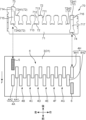
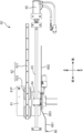
- FIG. 1 is a front view showing the overall configuration of the inkjet printer 1 according to an embodiment
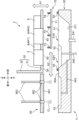
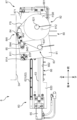
- Fig. 2 is a schematic cross-sectional view taken along line II-II in Fig. 1.
- directional indications such as up/down, front/back, and left/right are provided, but these are merely for the convenience of explanation and are not intended to limit the directions.
- the inkjet printer 1 is a printer that prints images on a wide and long workpiece W using an inkjet method, and includes a device frame 10, a workpiece transport section 2 and a carriage 3 incorporated in the device frame 10, and a dryer 19 arranged in front of the device frame 10. Note that the dryer 19 is not shown in Figure 1.
- the left-right direction is the main scanning direction when printing on the workpiece W
- the direction from the rear to the front is the sub-scanning direction, which is the transport direction F of the workpiece W.
- the device frame 10 forms a framework for mounting the various components of the inkjet printer 1.
- the work transport unit 2 is a mechanism that intermittently feeds the work W so that the work W progresses in a transport direction F from rear to front through a printing area where inkjet printing processing is performed.
- the carriage 3 is equipped with an ink head 4, a pre-processing head 5, a post-processing head 6, and a sub-tank (not shown), and moves back and forth in the left and right directions during the inkjet printing processing.
- the device frame 10 includes a central frame 111, a right frame 112, and a left frame 113.
- the central frame 111 forms a framework for mounting various components of the inkjet printer 1, and has a left-right width corresponding to the work transport section 2.
- the right frame 112 and the left frame 113 are erected to the right and left of the central frame 111, respectively.
- Between the right frame 112 and the left frame 113 is the printing area 12 where printing processing is performed on the work W.
- the printing area 12 is an area where the carriage 3 moves back and forth in the width direction perpendicular to the transport direction F of the work W, that is, in the main scanning direction.
- the right frame 112 forms the blade wipe area 13.
- the blade wipe area 13 is also an area where the carriage 3 is retracted when the printing process is not being performed, and is an area where, for maintenance purposes, purging of the heads 4, 5, and 6 and blade cleaning of the nozzle arrangement surface 40 (FIG. 7, FIG. 14A to FIG. 14C) of the heads 4, 5, and 6 exposed on the underside 3A of the carriage 3 are performed at the required timing.
- a blade wipe device 7 (first wipe device) that performs the blade cleaning is disposed in the blade wipe area 13.
- the blade wipe device 7 includes a blade wipe unit 70 having a blade BL (first wiping member) that wipes the nozzle arrangement surface 40.
- the underside 3A of the carriage 3 and the nozzle arrangement surface 40 are wiped with the blade BL.
- the purging process is a process of forcibly ejecting ink or processing liquid from each nozzle of the ink head 4, the pre-processing head 5, and the post-processing head 6.
- the blade cleaning is a process in which the nozzle arrangement surface 40 of the heads 4, 5, and 6 is wiped with a blade BL.
- the blade wiper device 7 also functions as a cap to prevent the heads 4, 5, and 6 from drying out when they are at rest.
- the left frame 113 forms the cloth wipe area 14.
- the cloth wipe area 14 is an area where cloth wipe cleaning is performed by cleaning the nozzle arrangement surface 40 using a cloth sheet.
- a cloth wipe device 8 (second wipe device) that performs the cloth wipe cleaning is arranged in the cloth wipe area 14.
- the cloth wipe device 8 includes a cloth wipe unit 80 having a cloth sheet FS (second wiping member).
- the cloth wipe area 14 is also a folding area for the carriage 3.
- the carriage 3 that scans the printing area 12 from right to left in the printing process temporarily enters the cloth wipe area 14 before scanning in the opposite direction. During maintenance, the carriage 3 is stopped in the cloth wipe area 14, and cloth wipe cleaning is performed by the cloth wipe device 8.
- the cloth wipe device 8 is also configured to be relatively small compared to the cloth wipe area 14. Therefore, when the carriage 3 is moved to the cloth wiping area 14, the underside 3A (nozzle arrangement surface 40) of the carriage 3 can be visually observed. This improves the ease of maintenance of the inkjet printer.
- the inkjet printer 1 of this embodiment is equipped with two different wiping members, the blade BL and the cloth sheet FS, for cleaning the heads.
- Cleaning with the blade BL is applied to at least the pre-processing head 5 and post-processing head 6.
- Cleaning with the cloth sheet FS is applied only to the ink head 4.
- an example is shown in which cleaning with the blade BL is applied to all heads 4, 5, and 6.
- the blade wipe device 7 is located in a blade wipe area 13 located on the right side (one side) of the printing area 12, and the cloth wipe device 8 is located in a cloth wipe area 14 located on the left side (the other side) of the printing area 12.
- the blade wipe area 13 and the cloth wipe area 14 are spaces that are essentially necessary for the printer 1 as a retreat space for the carriage 3 that moves back and forth in the printing area 12 and a space for the folding back operation. By utilizing such spaces to accommodate the blade wipe device 7 and the cloth wipe device 8, the printer 1 can be prevented from becoming larger even when equipped with two different types of wiping members.
- a single-axis robot 15 is attached near the top of the device frame 10 to move the carriage 3 back and forth in the left-right direction, i.e., the main scanning direction in the printing process.
- the single-axis robot 15 is disposed above the work transport section 2 so as to extend in the left-right direction.
- the single-axis robot 15 includes a linear motor 16 and a pair of upper and lower guide rails 17.
- the linear motor 16 includes a stator 161 disposed in the extension direction of the single-axis robot 15, and a mover 162 that moves along the guide rails 17.
- the pair of guide rails 17 extend in parallel in the left-right direction, and a moving block 163 carrying the mover 162 is engaged with the pair of guide rails 17.
- the carriage 3 is mounted on the moving block 163 and moved left or right by the single-axis robot 15.
- the work transport section 2 includes a feed roller 21 that pays out the work W before printing in the transport direction F, a take-up roller 22 that takes up the work W after printing, and a transport unit 20 arranged in the printing area 12.
- the feed roller 21 is the take-up shaft of the feed roll WA, which is a roll of the work W before printing.
- the take-up roller 22 is the take-up shaft of the take-up roll WB, which is a roll of the work W after the printing process.
- the feed roller 21 is arranged upstream of the printing area 12, and the take-up roller 22 is arranged downstream of the dryer 19.
- the path between the delivery roller 21 and the take-up roller 22 and passing through the printing area 12 is the transport path for the work W.
- a tension roller 23, a work guide 24, a transport roller 25, a pinch roller 26, a transport unit 20, a peeling roller 27, a loading roller 28, a dryer 19, and a folding roller 29 are arranged.
- the tension roller 23 applies a predetermined tension to the work W upstream of the transport roller 25.
- the work guide 24 changes the transport direction F of the work W from upward to forward, and transports the work W into the printing area 12.
- the transport roller 25 generates a transport force that intermittently feeds the work W in the printing area 12.
- the pinch roller 26 forms a transport nip with the transport roller 25. The pair of the transport roller 25 and the pinch roller 26 unwinds the work W from the delivery roll WA, and transports the work W intermittently in the transport direction F so that it passes through the printing area 12.
- the transport unit 20 is arranged to transport the workpiece W stably in the printing area 12 without floating or shaking.
- the transport unit 20 includes a drive roller 201 and a driven roller 202 arranged at a distance in the front-to-rear direction, and a transport belt 203 stretched across these rollers 201, 202.
- the workpiece W is transported in the transport direction F while in close contact with the surface of the transport belt 203.
- a platen 204 is arranged between the rollers 201, 202 and on the back side of the transport belt 203.
- ink and processing liquid are ejected from the ink head 4, pre-processing head 5, and post-processing head 6 onto the workpiece W.
- the peeling roller 27 is positioned diagonally above and in front of the drive roller 201, and serves to peel the printed work W from the surface of the conveyor belt 203, which is in close contact with the surface.
- the work W is peeled off from the conveyor belt 203 at a peeling section Bk at a predetermined peeling angle, and is sent to the downstream input roller 28. Between the peeling roller 27 and the input roller 28, the work W is in a slack state.
- the printed work W is sent from the input roller 28 to the dryer 19.
- the dryer 19 dries the wet work W by blowing hot air on it, for example.
- the turn-back roller 29 changes the transport direction F of the dried work W from the forward direction to the downward direction, and guides the work W to the take-up roller 22.
- the carriage 3 is supported by a movable block 163 in a cantilevered manner and moves back and forth in the main scanning direction (left and right direction) that intersects with the transport direction F.
- the carriage 3 comprises a carriage frame 30 that carries the ink head 4, pre-processing head 5, post-processing head 6, and a sub-tank (not shown).
- the carriage frame 30 includes a head support frame 31 and a back frame 32.
- the head support frame 31 is a horizontal plate that holds the heads 4, 5, and 6 described above.
- the back frame 32 is a vertical plate that extends upward from the rear edge of the head support frame 31.
- the back frame 32 is fixed to the movable block 163.
- FIG. 3 is an enlarged perspective view of the carriage 3 shown in FIG. 1.
- FIG. 3 shows the conveying direction F (sub-scanning direction) of the work W and the main scanning direction S, which is the moving direction of the carriage 3.
- FIG. 3 shows an example in which a plurality of ink heads 4 that eject ink for image formation onto the work W, and a pre-treatment head 5 and a post-treatment head 6 that eject non-coloring treatment liquid are mounted on the carriage 3. That is, in this embodiment, the carriage 3 is a head unit having the ink head 4 and the treatment heads 5 and 6.
- the actual carriage 3 also has a plurality of sub-tanks that supply the ink and the treatment liquid to these heads 4, 5, and 6. Note that the ink head 4, which is simply shown in FIG. 1, is more specifically shown in FIG. 3.
- Each of the ink heads 4 has a number of nozzles that eject ink droplets using an ejection method such as a piezo method using a piezo element or a thermal method using a heating element, and ink passages that guide ink to the nozzles.
- an ejection method such as a piezo method using a piezo element or a thermal method using a heating element
- ink passages that guide ink to the nozzles.
- a water-based pigment ink containing a water-based solvent, pigment, and binder resin can be used as the ink.
- the multiple ink heads 4 include first to eighth ink heads 4A to 4H that each eject eight different colors of ink.
- the ink heads 4A to 4H of each color are mounted on the head support frame 31 of the carriage 3 so as to be aligned in the main scanning direction S.
- Each of the ink heads 4A to 4H of each color has two heads.
- the first ink head 4A is composed of an upstream head 4A1 located upstream in the transport direction F, and a downstream head 4A2 located downstream of the upstream head 4A1 and shifted to the left in the main scanning direction S.
- the ink heads 4B to 4H of the other colors are similar.
- Each upstream head of these ink heads 4B to 4H is aligned in a row in the main scanning direction S at the same position as the upstream head 4A1 in the transport direction F, and each downstream head is aligned in a row in the main scanning direction S at the same position as the downstream head 4A2 in the transport direction F.
- the pre-treatment head 5 and the post-treatment head 6 are arranged at different positions from the ink head 4 in the transport direction F.
- the pre-treatment head 5 is arranged upstream of the ink head 4 in the transport direction F.
- FIG. 3 shows an example in which one pre-treatment head 5 is arranged near the left end of the ink head 4 array.
- the pre-treatment head 5 is to the left of the upstream head 4A1 of the first ink head 4A, and is aligned in front-to-back with the downstream head 4A2 at the same position in the main scanning direction S.
- the post-treatment head 6 is arranged downstream of the ink head 4 in the transport direction F.
- FIG 3 shows an example in which one post-treatment head 6 is arranged near the right end of the ink head 4 array.
- the post-treatment head 6 is to the right of the downstream head 4H2 of the eighth ink head 4H, and is aligned in front-to-back with the upstream head 4H1 at the same position in the main scanning direction S.
- the pretreatment head 5 ejects a pretreatment liquid for performing a predetermined pretreatment on the workpiece W.
- the pretreatment liquid is ejected from the pretreatment head 5 onto a position on the workpiece W where ink has not yet been ejected from the ink head 4.
- the pretreatment liquid is a non-coloring treatment liquid that does not develop color even when it adheres to the workpiece W, and is a treatment liquid that exhibits functions such as increasing the fixation of ink to the workpiece W and the coagulation of ink pigments.
- a treatment liquid in which a positively charged cationic resin is blended into the solvent can be used.
- the post-processing head 6 ejects a post-processing liquid for carrying out a predetermined post-processing on the workpiece W to which the ink has adhered.
- the post-processing liquid is ejected from the post-processing head 6 onto the position of the workpiece W after the ink has been ejected from the ink head 4.
- the post-processing liquid is a non-coloring processing liquid that does not develop color even when it adheres to the workpiece W, and is a processing liquid that exhibits a function of increasing the fixation and robustness of the ink image printed on the workpiece W by the ink head 4, such as resistance to rubbing and scraping.
- a silicone-based processing liquid can be used as such a post-processing liquid.
- Openings 31H are provided at the locations of the heads on the head support frame 31.
- the ink heads 4A-4F, pre-treatment head 5, and post-treatment head 6 are assembled to the head support frame 31 so that they fit into their respective openings 31H. From each opening 31H, the nozzle arrangement surface 40 located on the lower end surface of each head 4, 5, and 6 is exposed.
- the inkjet printer 1 includes a blade wiper device 7 that cleans the nozzle arrangement surface 40 (see FIG. 7 ) using a blade BL for maintenance of the heads 4, 5, and 6, and a fabric wiper device 8 that cleans the nozzle arrangement surface 40 using a fabric sheet FS.
- the nozzle arrangement surface 40 is a surface on which a large number of nozzle openings that eject ink and treatment liquid are arranged in a predetermined pattern in each of the heads 4, 5, and 6, and is exposed on the lower surface 3A of the carriage 3.
- the difference between the ink exemplified above and the pre-treatment liquid and the post-treatment liquid is the presence or absence of a binder resin.
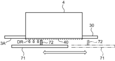
- the post-treatment liquid blade 74 that wipes the nozzle arrangement surface 40 of the post-treatment head 6 is attached near the front of the right end of the blade support plate 71.
- the post-treatment head 6 is arranged in line with the upstream head 4H1 of the eighth ink head 4H on the upstream and downstream sides of the transport direction F.
- the blade support plate 71 is provided with a retaining piece 716 and a window portion 717 near its right end.
- the retaining piece 716 supports an ink blade 72H1 that wipes the upstream head 4H1 at its rear edge.
- An ink blade 72H2 that wipes the downstream head 4H2 is supported on the edge of the recess 712 adjacent to the left side of the retaining piece 716.
- the window portion 717 is an opening arranged in front of the retaining piece 716.
- the post-treatment liquid blade 74 is supported at the opening edge on the front side of the window portion 717.
- the blade support plate 71 has a number of protrusions 713 arranged in correspondence with each of the blades 72, 73, and 74 described above.
- the protrusions 713 are connected to the rear end of the protrusion plate 711, the base edge of the recess 712, the rear end of the protrusion piece 714, and the base edge of the window portion 717. When viewed from above, these protrusions 713 are small projections that protrude in the direction of movement during wiping.
- the blades 72, 73, and 74 are each arranged on the corresponding protrusions 713. This arrangement makes it difficult for ink or treatment liquid adhering to the blades 72, 73, and 74 to adhere to the blade support plate 71.
- FIG. 6 shows the detailed structure of the ink blade 72, which corresponds to the blade BL (first wiping member) in FIG. 1.
- the pre-treatment liquid blade 73 and the post-treatment liquid blade 74 have a similar structure.
- the ink blade 72 includes a blade body 721, a first holder 722, and a second holder 723.
- the blade body 721 is a spatula-shaped plate that actually comes into contact with the nozzle arrangement surface 40 to perform the wiping operation.
- the upper end of the blade body 721 is located in a position that protrudes upward from the upper surface of the blade support plate 71.
- the first holder 722 and the second holder 723 are members that sandwich and hold the blade body 721.
- the first holder 722 is fitted into a recess provided in the protrusion 713 and fixed with a screw, supporting the lower back surface of the blade body 721.
- the second holder 723 is attached to the lower front surface of the blade body 721.
- the second holder 723 has a pair of openings 724, and the blade body 721 also has a through hole at the same position as the opening 724.
- the first holder 722 has a pair of claws 725.
- the claws 725 are inserted through the through holes and the opening 724, and engage the second holder 723 at the periphery of the opening 724. This engagement force causes the blade body 721 to be sandwiched between the first holder 722 and the second holder 723.
- the cloth wipe unit 80 is equipped with a cloth sheet roll FSR, which is a stack of cloth sheets for cloth wiping.
- the moving unit 60 moves the cloth wipe unit 80 in the front-to-rear direction.
- the wipe area 8W formed by the cloth sheet FS unwound from the cloth sheet roll FSR is pressed against the nozzle arrangement surface 40 of the ink head 4 exposed on the underside 3A of the carriage 3.
- Figure 8 shows this pressed state, and when the moving unit 60 moves the cloth wipe unit 80 backward from this state, the nozzle arrangement surface 40 is wiped by the cloth sheet FS in the wipe area 8W.
- the cloth wipe unit 80 is the unit that actually performs the cloth wipe cleaning.
- the moving unit 60 moves the cloth wipe unit 80 between a cleaning position where it cleans the lower surface 3A (nozzle arrangement surface 40) and a retracted position where no cleaning is performed.
- the cloth wipe unit 80 shown in FIG. 9A has been moved to the retracted position, and the cloth wipe unit 80 shown in FIG. 11 has been moved to the cleaning position.
- the moving unit 60 includes a moving plate 61, a linear guide 62, a ball screw 63, a nut 64, a cloth wiper moving motor 65, and a posture change guide 66.
- the movable plate 61 is a flat plate that is roughly rectangular in side view and can move in the front-rear direction along the linear guide 62.
- a cloth wipe unit 80 is mounted on the movable plate 61.
- a pivot pin 81P that protrudes to the left is attached near the corner of the rear and upper end of the movable plate 61.
- the pivot pin 81P is a pin that serves as the pivot axis for the cloth wipe unit 80.
- the cloth wipe unit 80 is mounted on the movable plate 61 so as to be rotatable around the axis of the pivot pin 81P.
- the linear guide 62 includes a guide base 620, a guide rail 621, and a block 622.
- the guide base 620 is a flat member that serves as a mounting base for the guide rail 621, the ball screw 63, the cloth wiper moving motor 65, and the posture change guide 66.
- the illustration of the guide base 620 is omitted in Figure 9A.
- the guide rail 621 is a rail that extends linearly in the front-to-rear direction.
- the block 622 is fitted into the guide rail 621 and can move in the front-to-rear direction along the guide rail 621.
- the moving plate 61 is fixed to the block 622.
- the ball screw 63 is journalled on the guide base 620 so as to extend in the front-rear direction parallel to the guide rail 621.
- the nut 64 is screwed onto the ball screw 63 and attached to the moving plate 61.
- the cloth wiper moving motor 65 is arranged so that its motor shaft is connected to the rear end of the ball screw 63, and drives the ball screw 63 to rotate forward or backward around its shaft. The rotation of the ball screw 63 moves the nut 64 in the front-rear direction, and accordingly the moving plate 61 moves in the front-rear direction while being guided by the guide rail 621.
- the cloth wipe unit 80 includes a base plate 81, a payout section 82, a take-up section 83, a pressure roller 84, a transport roller 85, and a transmission belt 86.
- the base plate 81 is a flat plate that is substantially square in side view and is larger than the movable plate 61.
- a bearing bush 811 protrudes from the right surface of the base plate 81 near the rear and upper corner.
- the bearing bush 811 has a rotation shaft hole 81A through which the pivot pin 81P of the movable plate 61 is inserted.
- the base plate 81 can rotate relative to the movable plate 61, with the bearing bush 811 supported by the pivot pin 81P as the pivot point.
- Abutment portion 812 protrudes from the left side of base plate 81 near the corner at the front end and bottom end.
- the abutment portion 812 is, for example, a roller that can rotate around an axis extending in the left-right direction.
- the corner where the abutment portion 812 is arranged is located diagonally from the corner where the bearing bush 811 is arranged.
- the abutment portion 812 abuts against the position change guide 66.
- FIG. 9A shows a state where the abutment portion 812 abuts against the first horizontal portion 661 of the position change guide 66, and the base plate 81 takes a horizontal position.
- FIG. 9A shows a state where the abutment portion 812 abuts against the first horizontal portion 661 of the position change guide 66, and the base plate 81 takes a horizontal position.
- FIG 11 shows a state where the abutment portion 812 abuts against the second horizontal portion 662 that is located higher than the first horizontal portion 661, and the base plate 81 rotates around the axis of the pivot pin 81P, and the front side is raised.
- the base plate 81 is fitted with an unwinding unit 82 and a take-up unit 83.
- the unwinding unit 82 unwinds the cloth sheet FS used for cloth wipe cleaning.
- the unwinding unit 82 has an unwinding roller 821 that holds a cloth sheet roll FSR, which is a roll of unused cloth sheet FS.
- a torque limiter 82L is attached to the rotation shaft of the unwinding roller 821.
- the take-up unit 83 takes up the cloth sheet FS after use in cloth wipe cleaning.
- the take-up unit 83 has a take-up roller 831 around which the used cloth sheet FS is wound.
- a torque limiter 83L is also attached to the rotation shaft of the take-up roller 831.
- a wiping area 8W using a cloth sheet FS is provided between the pay-out section 82 and the take-up section 83.
- the wiping area 8W is an area in which the cloth sheet portion of the long cloth sheet FS, which is made into the cloth sheet roll FSR, is pressed against the underside 3A of the carriage 3 and actually performs cloth wipe cleaning of the nozzle arrangement surface 40 is located. Unused cloth sheets FS are successively paid out from the cloth sheet roll FSR of the pay-out section 82 into the wiping area 8W. The cloth sheets FS used for cloth wipe cleaning in the wiping area 8W are successively taken up by the take-up section 83.
- the pressure roller 84 is made of an elastic roller, and supports the cloth sheet FS in the wiping area 8W.
- the pressure roller 84 serves to press the cloth sheet FS in the wiping area 8W against the lower surface 3A.
- the pressure roller 84 is supported on a shaft near the upper edge of the base plate 81 so that a portion of the pressure roller 84 protrudes upward from the upper edge of the base plate 81. As the cloth sheet FS is supported from below by such a pressure roller 84, the cloth sheet FS in the wiping area 8W also protrudes upward from the upper edge of the base plate 81.
- a one-way clutch (not shown) is attached to the rotation shaft of the pressure roller 84.
- the one-way clutch rotates the pressure roller 84 only in the payout direction of the cloth sheet FS.
- a pair of pulleys 842 are attached to both ends of the rotation shaft of the pressure roller 84.
- the pressure roller 84 is an elastically deformable roller, whereas the pulley 842 is made of a hard material that does not substantially deform elastically.
- the pair of pulleys 842 are pressed against the lower surface 3A to determine the positional relationship between the pressure roller 84 and the nozzle arrangement surface 40. Therefore, the amount of pressure of the cloth sheet FS by the pressure roller 84 onto the nozzle arrangement surface 40 can be made constant and uniform in the axial direction.
- a first guide roller 843 is disposed upstream of the pressure roller 84, and a second guide roller 844 is disposed downstream.
- a transport roller 85 and a tension roller 845 are disposed downstream of the second guide roller 844.
- the transport roller 85 sends the cloth sheet FS from the payout section 82 through the wiping area 8W toward the take-up section 83.
- a one-way clutch 851 is incorporated into the rotation shaft of the transport roller 85.
- the tension roller 845 applies tension to the cloth sheet FS being wound up in the take-up section 83.
- a gear (not shown) is attached to the shaft end of the transport roller 85.
- the base plate 81 rotates relative to the moving plate 61 with the bearing bush 811 as the pivot point, a driving force is applied to the gear, causing the transport roller 85 to rotate.
- the cloth sheet FS is sent downstream by the number of rotations of the transport roller 85.
- the rotation of the transport roller 85 also causes the used cloth sheet FS to be taken up by the take-up section 83.
- a transmission belt 86 is stretched between the transport roller 85 and the winding roller 831.
- the transport roller 85 rotates by a certain amount in response to a change in the position of the cloth wipe unit 80, the rotation is transmitted to the winding roller 831 by the transmission belt 86.
- the winding roller 831 winds up the cloth sheet FS by the number of rotations of the transport roller 85.
- a spray unit 87 is disposed between the first guide roller 843 and the pressure roller 84.
- the spray unit 87 has a spray gun 871 that sprays cleaning liquid consisting of pure water or a liquid containing a cleaning component.
- the spray unit 87 is attached to the left side plate of the device frame 10.
- the spray gun 871 sprays cleaning liquid onto the cloth sheet FS in the wiping area 8W upstream of the pressure roller 84. By wetting the cloth sheet FS with cleaning liquid immediately before cloth wipe cleaning, the cleaning effect of the nozzle arrangement surface 40 can be improved.
- FIG. 9A shows the retracted position in which the cloth wipe unit 80 does not clean the nozzle arrangement surface 40
- FIG. 11 shows the cleaning position in which the cloth wipe unit 80 cleans the nozzle arrangement surface 40.
- the contact portion 812 has climbed up the inclined portion 663 and reached the second horizontal portion 662.
- the contact portion 812 is raised by the height difference between the first horizontal portion 661 and the second horizontal portion 662, and the base plate 81 rotates around the axis of the pivot pin 81P by an angle corresponding to the amount of lift. This rotation also raises the wiping area 8W, and the portion of the cloth sheet FS supported by the pressure roller 84 abuts against the lower surface 3A (nozzle arrangement surface 40).
- the cloth sheet FS in the wiping area 8W is now in a state where it can be used to perform cloth wiping cleaning of the lower surface 3A.
- the moving plate 61 By driving the cloth wiper movement motor 65, the moving plate 61 is moved further backward, and the nozzle arrangement surface 40 is cleaned by the cloth sheet FS in the wiping area 8W.
- the ink heads 4 of each color are arranged in two rows, one behind the other.
- the width of the cloth sheet FS is sufficient to cover the two ink heads 4 arranged in the main scanning direction S. Therefore, it is desirable to move at least the wiping area 8W by a stroke equivalent to the two rows. For this reason, the front-to-rear length of the second horizontal portion 662 of the position change guide 66 is set longer than the stroke.
- the carriage 3 When the wiping area 8W has been moved to the rear end and cloth wipe cleaning is completed, the carriage 3 is raised slightly and the wiping area 8W is separated from the underside 3A.
- the cloth wiper movement motor 65 is then driven to return the moving plate 61 to the front.
- the contact position of the contact portion 812 changes from the second horizontal portion 6622 to the inclined portion 663, and then from the inclined portion 663 to the first horizontal portion 661.
- This causes the base plate 81 to rotate around the axis of the pivot pin 81P, and the cloth wipe unit 80 returns to a horizontal state, that is, the retracted position.
- the carriage 3 is then moved in the main scanning direction S by the distance of two heads, and the cloth wipe cleaning of the next ink head 4 is repeated in the above-mentioned procedure.
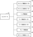
- Control configuration 12 is a block diagram showing part of the control configuration of the printer 1.
- the printer 1 includes a controller 33, a carriage drive motor 34, a carriage lift motor 35, a head drive unit 36, a work transport motor 37, a work take-up motor 38, a blade drive unit 75, and the cloth wiper movement motor 65 described above, whose operations are controlled by the controller 33.
- the carriage drive motor 34 generates a driving force to move the carriage 3 left and right between the blade wipe area 13 and the fabric wipe area 14 through the printing area 12.
- the carriage drive motor 34 corresponds to the linear motor 16 shown in FIG. 1.
- the carriage lift motor 35 generates a driving force to move the carriage 3 up and down in the blade wipe area 13 and the fabric wipe area 14.
- the head drive unit 36 executes the ejection operation of the ink, pre-treatment liquid, and post-treatment liquid from each of the heads 4, 5, and 6.
- the work transport motor 37 is a motor that serves as a driving source to transport the work W in the transport direction F in the printer 1.
- the drive motors of the transport roller 25, the drive roller 201 of the transport unit 20, and the like correspond to the work transport motor 37.
- the work winding motor 38 is a motor that serves as a driving source to rotate the winding roller 22 that winds up the work W after printing.
- the blade driving unit 75 operates the blade wiper device 7 to perform maintenance including purging of the heads 4, 5, and 6 and blade cleaning. Specifically, the blade driving unit 75 ejects high-pressure ink, pre-treatment liquid, and post-treatment liquid from the heads 4, 5, and 6 as a purging process to clean the nozzles. Also, as a blade cleaning process, the blades 72, 73, and 74 of the blade wipe unit 70 are moved in close proximity to the nozzle arrangement surfaces 40 of the heads 4, 5, and 6 in the case of non-contact wiping, which will be described later, and in contact with the nozzle arrangement surfaces 40 in the case of contact wiping.
- the cloth wiper movement motor 65 moves the moving plate 61 on which the cloth wipe unit 80 is mounted, and performs cloth wipe cleaning of the ink head 4.
- the controller 33 sets a cleaning sequence for the nozzle arrangement surface 40 by the cloth wipe unit 80, and controls the cloth wiper movement motor 65 and the carriage drive motor 34, etc., based on the cleaning sequence.
- the controller 33 is made up of a processor that operates according to a program, and generally controls the operation of each part of the printer 1. With regard to cleaning control of the heads 4, 5, and 6, the controller 33 controls the blade wiping device 7 (first wiping device) and the cloth wiping device 8 (second wiping device) to perform the required blade cleaning and cloth wiping cleaning.
- the controller 33 executes a two-stage wiping in which the nozzle arrangement surface 40 is wiped by both the blade wiper device 7 and the cloth wiper device 8.
- the wiping order is that the blade wiper device 7 first wipes the nozzle arrangement surface 40, and then the cloth wiper device 8 wipes the nozzle arrangement surface 40.
- the controller 33 sequentially executes a first wiping in which the ink blade 72 does not contact the nozzle arrangement surface 40, and a second wiping in which the ink blade 72 contacts the nozzle arrangement surface 40.
- the controller 33 wipes the nozzle arrangement surface 40 only by the blade wiper device 7.
- the controller 33 executes a purge in which the ink and the treatment liquid are forcibly ejected from the heads 4, 5, and 6 before the blade cleaning by the blade wiper device 7.
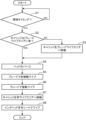
- FIG. 13 is a flowchart showing an example of the cleaning operation of the heads 4, 5, and 6 in the printer 1.
- the controller 33 judges whether or not the current time is the timing for cleaning (step S1). Whether or not it is the timing for cleaning is judged by referring to the accumulated printing time and printing area since the previous head cleaning, the number of operating days, and the like. Note that whether or not it is the timing for cleaning may be judged by considering not only the periodic factors listed above, but also non-periodic factors such as when high density printing is performed continuously or when a non-ejecting head is detected. If it is not the timing for cleaning (NO in step S1), the controller 33 puts the blade wiper device 7 and the cloth wiper device 8 into a standby state.
- step S1 If it is time for cleaning (YES in step S1), it is determined whether the carriage 3 is in the blade wipe area 13 (step S2). If the carriage 3 is not in the blade wipe area 13 (NO in step S2), the controller 33 controls the carriage drive motor 34 to move the carriage 3 to the blade wipe area 13 (step S3).
- the controller 33 executes blade cleaning.
- the controller 33 controls the blade drive unit 75 to first execute a purge that forcibly ejects ink and treatment liquid from the heads 4, 5, and 6 (step S4).
- the role of the purge is to expel air bubbles trapped in each nozzle of the heads 4, 5, and 6, and to blow away solid matter adhering to the nozzle arrangement surface 40 with the purge flow.
- the ink purge flow also softens solid matter derived from the ink, making it easier to peel off.
- the purge amount can be set in the range of about 3 ml to 60 ml per head. It is also possible to execute purging only on the ink head 4. Also, if only a specific ink head 4 has a clogged nozzle, it is also possible to execute purging on only that specific head. In this case, to prevent adverse effects on the heads (damage to the water-repellent film) due to empty wiping, it is desirable to eject a small amount (about 0.2 ml to 1.0 ml) of ink or treatment liquid from heads other than the specific ink head 4.
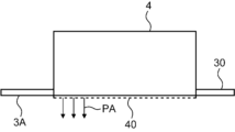
- the controller 33 causes the blade wipe unit 70 to perform a non-contact wipe (first wipe) of the heads 4, 5, and 6 (step S5).
- a gap of about 0.2 mm to 0.8 mm is provided between the blade body 721 of the ink blade 72 and the nozzle arrangement surface 40 of the ink head 4, and the wiping operation is performed.
- the controller 33 controls the carriage lift motor 35 to lower the carriage 3 so that the gap is formed.
- This non-contact wipe wipes away droplets hanging from the nozzle arrangement surface 40 of the heads 4, 5, and 6 after purging.
- the movement speed of the blade wipe unit 70 in the non-contact wipe can be selected from a range of about 10 mm/s to 100 mm/s.
- FIG. 16 is a front view showing the overall configuration of an inkjet printer 1A according to a modified embodiment.
- a right frame 112A is disposed on the right side of the printing area 12, defining the maintenance area 13A.
- the maintenance area 13A contains a blade wipe device 7 and a fabric wipe device 8. That is, with the printer 1A, both blade cleaning and fabric wipe cleaning can be performed in the maintenance area 13A.
Landscapes
- Ink Jet (AREA)
Abstract
L'invention concerne une imprimante à jet d'encre comprenant : une tête de liquide de traitement pour décharger un liquide de traitement ; une tête d'encre pour décharger de l'encre ; un premier élément d'essuyage pour essuyer une surface d'agencement de buse de la tête de liquide de traitement ; et un second élément d'essuyage pour essuyer une surface d'agencement de buse de la tête d'encre, le second élément d'essuyage étant différent du premier élément d'essuyage.
Priority Applications (5)
| Application Number | Priority Date | Filing Date | Title |
|---|---|---|---|
| CN202480036196.1A CN121219138A (zh) | 2023-06-06 | 2024-06-06 | 喷墨式打印机及头单元的清扫方法 |
| EP24819386.4A EP4696512A1 (fr) | 2023-06-06 | 2024-06-06 | Imprimante à jet d'encre et procédé de nettoyage d'unité de tête |
| PCT/JP2024/020698 WO2024253158A1 (fr) | 2023-06-06 | 2024-06-06 | Imprimante à jet d'encre et procédé de nettoyage d'unité de tête |
| JP2025502680A JP7704997B2 (ja) | 2023-06-06 | 2024-06-06 | インクジェット式プリンターおよびヘッドユニットの清掃方法 |
| JP2025105808A JP2025128396A (ja) | 2023-06-06 | 2025-06-23 | インクジェット式プリンターおよびヘッドユニットの清掃方法 |
Applications Claiming Priority (2)
| Application Number | Priority Date | Filing Date | Title |
|---|---|---|---|
| JP2023-092878 | 2023-06-06 | ||
| JP2023092878 | 2023-06-06 |
Publications (1)
| Publication Number | Publication Date |
|---|---|
| WO2024252720A1 true WO2024252720A1 (fr) | 2024-12-12 |
Family
ID=93795787
Family Applications (1)
| Application Number | Title | Priority Date | Filing Date |
|---|---|---|---|
| PCT/JP2024/002062 Ceased WO2024252720A1 (fr) | 2023-06-06 | 2024-01-24 | Imprimante à jet d'encre et procédé de nettoyage d'unité de tête |
Country Status (1)
| Country | Link |
|---|---|
| WO (1) | WO2024252720A1 (fr) |
Citations (6)
| Publication number | Priority date | Publication date | Assignee | Title |
|---|---|---|---|---|
| JPH09254400A (ja) * | 1996-03-26 | 1997-09-30 | Canon Inc | インクジェット記録装置 |
| JP2004330750A (ja) * | 2003-05-12 | 2004-11-25 | Seiko Epson Corp | 液体噴射ヘッド及び液体噴射装置 |
| JP2008143039A (ja) * | 2006-12-11 | 2008-06-26 | Fuji Xerox Co Ltd | 液滴吐出装置 |
| JP2010221713A (ja) * | 2004-07-14 | 2010-10-07 | Seiko Epson Corp | 液体噴射装置および液体払拭装置 |
| JP2019030990A (ja) * | 2017-08-07 | 2019-02-28 | セイコーエプソン株式会社 | 液体噴射装置 |
| JP2023048762A (ja) * | 2021-09-28 | 2023-04-07 | 京セラドキュメントソリューションズ株式会社 | ワイピング装置並びに画像形成装置およびワイピング方法 |
-
2024
- 2024-01-24 WO PCT/JP2024/002062 patent/WO2024252720A1/fr not_active Ceased
Patent Citations (6)
| Publication number | Priority date | Publication date | Assignee | Title |
|---|---|---|---|---|
| JPH09254400A (ja) * | 1996-03-26 | 1997-09-30 | Canon Inc | インクジェット記録装置 |
| JP2004330750A (ja) * | 2003-05-12 | 2004-11-25 | Seiko Epson Corp | 液体噴射ヘッド及び液体噴射装置 |
| JP2010221713A (ja) * | 2004-07-14 | 2010-10-07 | Seiko Epson Corp | 液体噴射装置および液体払拭装置 |
| JP2008143039A (ja) * | 2006-12-11 | 2008-06-26 | Fuji Xerox Co Ltd | 液滴吐出装置 |
| JP2019030990A (ja) * | 2017-08-07 | 2019-02-28 | セイコーエプソン株式会社 | 液体噴射装置 |
| JP2023048762A (ja) * | 2021-09-28 | 2023-04-07 | 京セラドキュメントソリューションズ株式会社 | ワイピング装置並びに画像形成装置およびワイピング方法 |
Similar Documents
| Publication | Publication Date | Title |
|---|---|---|
| EP3530466B1 (fr) | Dispositif d'essuyage, dispositif de maintenance de tête et appareil de décharge de liquide | |
| JP6044307B2 (ja) | 液体噴射装置 | |
| JP5352409B2 (ja) | クリーナカートリッジ及びクリーニング装置並びに画像形成装置 | |
| JP5259458B2 (ja) | インクジェット記録装置及び記録ヘッドのメンテナンス方法 | |
| US10457053B2 (en) | Ink jet printer | |
| JP2017052117A (ja) | 液体噴射装置及びクリーニング装置 | |
| JP6194576B2 (ja) | 液体噴射装置 | |
| JP2018079684A (ja) | ヘッド清掃装置、ヘッドメンテナンス装置、液体を吐出する装置 | |
| US20030081050A1 (en) | Inkjet printer cartridge adapted for enhanced cleaning thereof and method of assembling the printer cartridge | |
| JP2025065513A (ja) | インクジェット記録装置 | |
| JP6418207B2 (ja) | 液体噴射装置 | |
| JP2012051132A (ja) | インクジェット記録装置 | |
| JP2017071135A (ja) | クリーニング装置およびそれを備えたインクジェットプリンタ | |
| JP3018646B2 (ja) | インクジェット印刷装置のヘッドクリーニング装置 | |
| JP7704997B2 (ja) | インクジェット式プリンターおよびヘッドユニットの清掃方法 | |
| WO2024252720A1 (fr) | Imprimante à jet d'encre et procédé de nettoyage d'unité de tête | |
| JP2015085618A (ja) | インクジェット記録装置 | |
| JP3897453B2 (ja) | インクジェット記録装置 | |
| JP3166518B2 (ja) | インクジェット装置及びワイピング部材 | |
| JP4536858B2 (ja) | インクジェットプリンタ | |
| JP2010012739A (ja) | 液体吐出記録装置及びインクジェット記録装置 | |
| JP4408485B2 (ja) | インクジェットプリンタにおけるワイピング装置 | |
| JP6474684B2 (ja) | 液体払拭装置及び液体払拭方法 | |
| JP4368465B2 (ja) | インクジェットプリンタ | |
| WO2024202999A1 (fr) | Dispositif et procédé permettant de nettoyer une surface de placement de buses |
Legal Events
| Date | Code | Title | Description |
|---|---|---|---|
| 121 | Ep: the epo has been informed by wipo that ep was designated in this application |
Ref document number: 24818959 Country of ref document: EP Kind code of ref document: A1 |
|
| NENP | Non-entry into the national phase |
Ref country code: DE |