WO2024252720A1 - インクジェット式プリンターおよびヘッドユニットの清掃方法 - Google Patents
インクジェット式プリンターおよびヘッドユニットの清掃方法 Download PDFInfo
- Publication number
- WO2024252720A1 WO2024252720A1 PCT/JP2024/002062 JP2024002062W WO2024252720A1 WO 2024252720 A1 WO2024252720 A1 WO 2024252720A1 JP 2024002062 W JP2024002062 W JP 2024002062W WO 2024252720 A1 WO2024252720 A1 WO 2024252720A1
- Authority
- WO
- WIPO (PCT)
- Prior art keywords
- wiping
- head
- ink
- blade
- wipe
- Prior art date
- Legal status (The legal status is an assumption and is not a legal conclusion. Google has not performed a legal analysis and makes no representation as to the accuracy of the status listed.)
- Ceased
Links
Images


Classifications
-
- B—PERFORMING OPERATIONS; TRANSPORTING
- B41—PRINTING; LINING MACHINES; TYPEWRITERS; STAMPS
- B41J—TYPEWRITERS; SELECTIVE PRINTING MECHANISMS, i.e. MECHANISMS PRINTING OTHERWISE THAN FROM A FORME; CORRECTION OF TYPOGRAPHICAL ERRORS
- B41J2/00—Typewriters or selective printing mechanisms characterised by the printing or marking process for which they are designed
- B41J2/005—Typewriters or selective printing mechanisms characterised by the printing or marking process for which they are designed characterised by bringing liquid or particles selectively into contact with a printing material
- B41J2/01—Ink jet
- B41J2/135—Nozzles
- B41J2/165—Prevention or detection of nozzle clogging, e.g. cleaning, capping or moistening for nozzles
Definitions
- An inkjet printer includes a treatment liquid head that ejects treatment liquid, an ink head that ejects ink, a first wiping member that wipes the nozzle arrangement surface of the treatment liquid head, and a second wiping member different from the first wiping member that wipes the nozzle arrangement surface of the ink head.
- a method for cleaning a head unit is a method for cleaning a head unit having a treatment liquid head that ejects a treatment liquid and an ink head that ejects ink, in which a nozzle arrangement surface of the treatment liquid head is wiped with a first wiping member, and a nozzle arrangement surface of the ink head is wiped with a second wiping member different from the first wiping member.
- FIG. 1 is a front view showing the overall configuration of an inkjet printer according to an embodiment of the present disclosure.
- FIG. 2 is a cross-sectional view taken along line II-II of FIG. 1 with a printing press added.
- FIG. 3 is an enlarged perspective view of the carriage shown in FIG.
- FIG. 4 is a perspective view of a blade wiping device (first wiping device) that is installed in the printer for cleaning the treatment liquid head and the ink head.
- the upper diagram in FIG. 5 is a plan view of the blade wipe unit, and the lower diagram in FIG. 5 is a plan view showing the arrangement of the heads mounted on the carriage.
- FIG. 6 is a perspective view of an ink blade provided in the blade wipe unit.
- FIG. 7 is a schematic cross-sectional view of the carriage and the blade wipe unit.
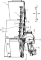
- FIG. 8 is a perspective view of a cloth wiping device (second wiping device) that is installed in a printer for cleaning the ink heads, showing the cleaning state of the nozzle arrangement surface.
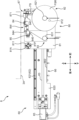
- FIG. 9A is a left side view of the cloth wiping device.
- FIG. 9B is a side view of the mobile unit.
- FIG. 10 is a perspective view of the cloth wipe unit.
- FIG. 11 is a left side view of the cloth wiping device, showing a state in which the cloth wiping unit is in the cleaning position.
- FIG. 12 is a block diagram showing a part of the control configuration of the inkjet printer.
- FIG. 13 is a flow chart showing an example of a cleaning operation for the ink head and the treatment liquid head in an ink jet printer.
- FIG. 14A is a diagram showing a procedure for cleaning an ink head using a blade wipe unit.
- FIG. 14B is a diagram showing a procedure for cleaning the ink head using the blade wipe unit.
- FIG. 14C is a diagram showing a procedure for cleaning the ink head using a blade wipe unit.
- FIG. 15 is a flow chart showing another example of the cleaning operation for the ink heads and the treatment liquid heads.
- FIG. 16 is a front view showing the overall configuration of an ink jet printer according to a modified embodiment.
- an example of an inkjet printer of the present disclosure is a printer equipped with an ink head that ejects ink for forming an image onto a wide, long recording medium.
- An example of a head unit cleaning method of the present disclosure is applied to a head unit equipped in the printer.
- the inkjet printer of this embodiment is suitable for digital textile printing, which uses an inkjet method to print images such as characters and patterns onto a recording medium (work) made of fabric such as woven or knitted fabric.
- the inkjet printer and cleaning method according to the present disclosure can also be used for printing various inkjet images onto recording media such as paper sheets and resin sheets.
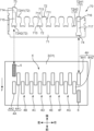
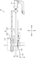
- FIG. 1 is a front view showing the overall configuration of the inkjet printer 1 according to an embodiment
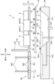
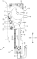
- Fig. 2 is a schematic cross-sectional view taken along line II-II in Fig. 1.
- directional indications such as up/down, front/back, and left/right are provided, but these are merely for the convenience of explanation and are not intended to limit the directions.
- the inkjet printer 1 is a printer that prints images on a wide and long workpiece W using an inkjet method, and includes a device frame 10, a workpiece transport section 2 and a carriage 3 incorporated in the device frame 10, and a dryer 19 arranged in front of the device frame 10. Note that the dryer 19 is not shown in Figure 1.
- the left-right direction is the main scanning direction when printing on the workpiece W
- the direction from the rear to the front is the sub-scanning direction, which is the transport direction F of the workpiece W.
- the device frame 10 forms a framework for mounting the various components of the inkjet printer 1.
- the work transport unit 2 is a mechanism that intermittently feeds the work W so that the work W progresses in a transport direction F from rear to front through a printing area where inkjet printing processing is performed.
- the carriage 3 is equipped with an ink head 4, a pre-processing head 5, a post-processing head 6, and a sub-tank (not shown), and moves back and forth in the left and right directions during the inkjet printing processing.
- the device frame 10 includes a central frame 111, a right frame 112, and a left frame 113.
- the central frame 111 forms a framework for mounting various components of the inkjet printer 1, and has a left-right width corresponding to the work transport section 2.
- the right frame 112 and the left frame 113 are erected to the right and left of the central frame 111, respectively.
- Between the right frame 112 and the left frame 113 is the printing area 12 where printing processing is performed on the work W.
- the printing area 12 is an area where the carriage 3 moves back and forth in the width direction perpendicular to the transport direction F of the work W, that is, in the main scanning direction.
- the right frame 112 forms the blade wipe area 13.
- the blade wipe area 13 is also an area where the carriage 3 is retracted when the printing process is not being performed, and is an area where, for maintenance purposes, purging of the heads 4, 5, and 6 and blade cleaning of the nozzle arrangement surface 40 (FIG. 7, FIG. 14A to FIG. 14C) of the heads 4, 5, and 6 exposed on the underside 3A of the carriage 3 are performed at the required timing.
- a blade wipe device 7 (first wipe device) that performs the blade cleaning is disposed in the blade wipe area 13.
- the blade wipe device 7 includes a blade wipe unit 70 having a blade BL (first wiping member) that wipes the nozzle arrangement surface 40.
- the underside 3A of the carriage 3 and the nozzle arrangement surface 40 are wiped with the blade BL.
- the purging process is a process of forcibly ejecting ink or processing liquid from each nozzle of the ink head 4, the pre-processing head 5, and the post-processing head 6.
- the blade cleaning is a process in which the nozzle arrangement surface 40 of the heads 4, 5, and 6 is wiped with a blade BL.
- the blade wiper device 7 also functions as a cap to prevent the heads 4, 5, and 6 from drying out when they are at rest.
- the left frame 113 forms the cloth wipe area 14.
- the cloth wipe area 14 is an area where cloth wipe cleaning is performed by cleaning the nozzle arrangement surface 40 using a cloth sheet.
- a cloth wipe device 8 (second wipe device) that performs the cloth wipe cleaning is arranged in the cloth wipe area 14.
- the cloth wipe device 8 includes a cloth wipe unit 80 having a cloth sheet FS (second wiping member).
- the cloth wipe area 14 is also a folding area for the carriage 3.
- the carriage 3 that scans the printing area 12 from right to left in the printing process temporarily enters the cloth wipe area 14 before scanning in the opposite direction. During maintenance, the carriage 3 is stopped in the cloth wipe area 14, and cloth wipe cleaning is performed by the cloth wipe device 8.
- the cloth wipe device 8 is also configured to be relatively small compared to the cloth wipe area 14. Therefore, when the carriage 3 is moved to the cloth wiping area 14, the underside 3A (nozzle arrangement surface 40) of the carriage 3 can be visually observed. This improves the ease of maintenance of the inkjet printer.
- the inkjet printer 1 of this embodiment is equipped with two different wiping members, the blade BL and the cloth sheet FS, for cleaning the heads.
- Cleaning with the blade BL is applied to at least the pre-processing head 5 and post-processing head 6.
- Cleaning with the cloth sheet FS is applied only to the ink head 4.
- an example is shown in which cleaning with the blade BL is applied to all heads 4, 5, and 6.
- the blade wipe device 7 is located in a blade wipe area 13 located on the right side (one side) of the printing area 12, and the cloth wipe device 8 is located in a cloth wipe area 14 located on the left side (the other side) of the printing area 12.
- the blade wipe area 13 and the cloth wipe area 14 are spaces that are essentially necessary for the printer 1 as a retreat space for the carriage 3 that moves back and forth in the printing area 12 and a space for the folding back operation. By utilizing such spaces to accommodate the blade wipe device 7 and the cloth wipe device 8, the printer 1 can be prevented from becoming larger even when equipped with two different types of wiping members.
- a single-axis robot 15 is attached near the top of the device frame 10 to move the carriage 3 back and forth in the left-right direction, i.e., the main scanning direction in the printing process.
- the single-axis robot 15 is disposed above the work transport section 2 so as to extend in the left-right direction.
- the single-axis robot 15 includes a linear motor 16 and a pair of upper and lower guide rails 17.
- the linear motor 16 includes a stator 161 disposed in the extension direction of the single-axis robot 15, and a mover 162 that moves along the guide rails 17.
- the pair of guide rails 17 extend in parallel in the left-right direction, and a moving block 163 carrying the mover 162 is engaged with the pair of guide rails 17.
- the carriage 3 is mounted on the moving block 163 and moved left or right by the single-axis robot 15.
- the work transport section 2 includes a feed roller 21 that pays out the work W before printing in the transport direction F, a take-up roller 22 that takes up the work W after printing, and a transport unit 20 arranged in the printing area 12.
- the feed roller 21 is the take-up shaft of the feed roll WA, which is a roll of the work W before printing.
- the take-up roller 22 is the take-up shaft of the take-up roll WB, which is a roll of the work W after the printing process.
- the feed roller 21 is arranged upstream of the printing area 12, and the take-up roller 22 is arranged downstream of the dryer 19.
- the path between the delivery roller 21 and the take-up roller 22 and passing through the printing area 12 is the transport path for the work W.
- a tension roller 23, a work guide 24, a transport roller 25, a pinch roller 26, a transport unit 20, a peeling roller 27, a loading roller 28, a dryer 19, and a folding roller 29 are arranged.
- the tension roller 23 applies a predetermined tension to the work W upstream of the transport roller 25.
- the work guide 24 changes the transport direction F of the work W from upward to forward, and transports the work W into the printing area 12.
- the transport roller 25 generates a transport force that intermittently feeds the work W in the printing area 12.
- the pinch roller 26 forms a transport nip with the transport roller 25. The pair of the transport roller 25 and the pinch roller 26 unwinds the work W from the delivery roll WA, and transports the work W intermittently in the transport direction F so that it passes through the printing area 12.
- the transport unit 20 is arranged to transport the workpiece W stably in the printing area 12 without floating or shaking.
- the transport unit 20 includes a drive roller 201 and a driven roller 202 arranged at a distance in the front-to-rear direction, and a transport belt 203 stretched across these rollers 201, 202.
- the workpiece W is transported in the transport direction F while in close contact with the surface of the transport belt 203.
- a platen 204 is arranged between the rollers 201, 202 and on the back side of the transport belt 203.
- ink and processing liquid are ejected from the ink head 4, pre-processing head 5, and post-processing head 6 onto the workpiece W.
- the peeling roller 27 is positioned diagonally above and in front of the drive roller 201, and serves to peel the printed work W from the surface of the conveyor belt 203, which is in close contact with the surface.
- the work W is peeled off from the conveyor belt 203 at a peeling section Bk at a predetermined peeling angle, and is sent to the downstream input roller 28. Between the peeling roller 27 and the input roller 28, the work W is in a slack state.
- the printed work W is sent from the input roller 28 to the dryer 19.
- the dryer 19 dries the wet work W by blowing hot air on it, for example.
- the turn-back roller 29 changes the transport direction F of the dried work W from the forward direction to the downward direction, and guides the work W to the take-up roller 22.
- the carriage 3 is supported by a movable block 163 in a cantilevered manner and moves back and forth in the main scanning direction (left and right direction) that intersects with the transport direction F.
- the carriage 3 comprises a carriage frame 30 that carries the ink head 4, pre-processing head 5, post-processing head 6, and a sub-tank (not shown).
- the carriage frame 30 includes a head support frame 31 and a back frame 32.
- the head support frame 31 is a horizontal plate that holds the heads 4, 5, and 6 described above.
- the back frame 32 is a vertical plate that extends upward from the rear edge of the head support frame 31.
- the back frame 32 is fixed to the movable block 163.
- FIG. 3 is an enlarged perspective view of the carriage 3 shown in FIG. 1.
- FIG. 3 shows the conveying direction F (sub-scanning direction) of the work W and the main scanning direction S, which is the moving direction of the carriage 3.
- FIG. 3 shows an example in which a plurality of ink heads 4 that eject ink for image formation onto the work W, and a pre-treatment head 5 and a post-treatment head 6 that eject non-coloring treatment liquid are mounted on the carriage 3. That is, in this embodiment, the carriage 3 is a head unit having the ink head 4 and the treatment heads 5 and 6.
- the actual carriage 3 also has a plurality of sub-tanks that supply the ink and the treatment liquid to these heads 4, 5, and 6. Note that the ink head 4, which is simply shown in FIG. 1, is more specifically shown in FIG. 3.
- Each of the ink heads 4 has a number of nozzles that eject ink droplets using an ejection method such as a piezo method using a piezo element or a thermal method using a heating element, and ink passages that guide ink to the nozzles.
- an ejection method such as a piezo method using a piezo element or a thermal method using a heating element
- ink passages that guide ink to the nozzles.
- a water-based pigment ink containing a water-based solvent, pigment, and binder resin can be used as the ink.
- the multiple ink heads 4 include first to eighth ink heads 4A to 4H that each eject eight different colors of ink.
- the ink heads 4A to 4H of each color are mounted on the head support frame 31 of the carriage 3 so as to be aligned in the main scanning direction S.
- Each of the ink heads 4A to 4H of each color has two heads.
- the first ink head 4A is composed of an upstream head 4A1 located upstream in the transport direction F, and a downstream head 4A2 located downstream of the upstream head 4A1 and shifted to the left in the main scanning direction S.
- the ink heads 4B to 4H of the other colors are similar.
- Each upstream head of these ink heads 4B to 4H is aligned in a row in the main scanning direction S at the same position as the upstream head 4A1 in the transport direction F, and each downstream head is aligned in a row in the main scanning direction S at the same position as the downstream head 4A2 in the transport direction F.
- the pre-treatment head 5 and the post-treatment head 6 are arranged at different positions from the ink head 4 in the transport direction F.
- the pre-treatment head 5 is arranged upstream of the ink head 4 in the transport direction F.
- FIG. 3 shows an example in which one pre-treatment head 5 is arranged near the left end of the ink head 4 array.
- the pre-treatment head 5 is to the left of the upstream head 4A1 of the first ink head 4A, and is aligned in front-to-back with the downstream head 4A2 at the same position in the main scanning direction S.
- the post-treatment head 6 is arranged downstream of the ink head 4 in the transport direction F.
- FIG 3 shows an example in which one post-treatment head 6 is arranged near the right end of the ink head 4 array.
- the post-treatment head 6 is to the right of the downstream head 4H2 of the eighth ink head 4H, and is aligned in front-to-back with the upstream head 4H1 at the same position in the main scanning direction S.
- the pretreatment head 5 ejects a pretreatment liquid for performing a predetermined pretreatment on the workpiece W.
- the pretreatment liquid is ejected from the pretreatment head 5 onto a position on the workpiece W where ink has not yet been ejected from the ink head 4.
- the pretreatment liquid is a non-coloring treatment liquid that does not develop color even when it adheres to the workpiece W, and is a treatment liquid that exhibits functions such as increasing the fixation of ink to the workpiece W and the coagulation of ink pigments.
- a treatment liquid in which a positively charged cationic resin is blended into the solvent can be used.
- the post-processing head 6 ejects a post-processing liquid for carrying out a predetermined post-processing on the workpiece W to which the ink has adhered.
- the post-processing liquid is ejected from the post-processing head 6 onto the position of the workpiece W after the ink has been ejected from the ink head 4.
- the post-processing liquid is a non-coloring processing liquid that does not develop color even when it adheres to the workpiece W, and is a processing liquid that exhibits a function of increasing the fixation and robustness of the ink image printed on the workpiece W by the ink head 4, such as resistance to rubbing and scraping.
- a silicone-based processing liquid can be used as such a post-processing liquid.
- Openings 31H are provided at the locations of the heads on the head support frame 31.
- the ink heads 4A-4F, pre-treatment head 5, and post-treatment head 6 are assembled to the head support frame 31 so that they fit into their respective openings 31H. From each opening 31H, the nozzle arrangement surface 40 located on the lower end surface of each head 4, 5, and 6 is exposed.
- the inkjet printer 1 includes a blade wiper device 7 that cleans the nozzle arrangement surface 40 (see FIG. 7 ) using a blade BL for maintenance of the heads 4, 5, and 6, and a fabric wiper device 8 that cleans the nozzle arrangement surface 40 using a fabric sheet FS.
- the nozzle arrangement surface 40 is a surface on which a large number of nozzle openings that eject ink and treatment liquid are arranged in a predetermined pattern in each of the heads 4, 5, and 6, and is exposed on the lower surface 3A of the carriage 3.
- the difference between the ink exemplified above and the pre-treatment liquid and the post-treatment liquid is the presence or absence of a binder resin.
- the post-treatment liquid blade 74 that wipes the nozzle arrangement surface 40 of the post-treatment head 6 is attached near the front of the right end of the blade support plate 71.
- the post-treatment head 6 is arranged in line with the upstream head 4H1 of the eighth ink head 4H on the upstream and downstream sides of the transport direction F.
- the blade support plate 71 is provided with a retaining piece 716 and a window portion 717 near its right end.
- the retaining piece 716 supports an ink blade 72H1 that wipes the upstream head 4H1 at its rear edge.
- An ink blade 72H2 that wipes the downstream head 4H2 is supported on the edge of the recess 712 adjacent to the left side of the retaining piece 716.
- the window portion 717 is an opening arranged in front of the retaining piece 716.
- the post-treatment liquid blade 74 is supported at the opening edge on the front side of the window portion 717.
- the blade support plate 71 has a number of protrusions 713 arranged in correspondence with each of the blades 72, 73, and 74 described above.
- the protrusions 713 are connected to the rear end of the protrusion plate 711, the base edge of the recess 712, the rear end of the protrusion piece 714, and the base edge of the window portion 717. When viewed from above, these protrusions 713 are small projections that protrude in the direction of movement during wiping.
- the blades 72, 73, and 74 are each arranged on the corresponding protrusions 713. This arrangement makes it difficult for ink or treatment liquid adhering to the blades 72, 73, and 74 to adhere to the blade support plate 71.
- FIG. 6 shows the detailed structure of the ink blade 72, which corresponds to the blade BL (first wiping member) in FIG. 1.
- the pre-treatment liquid blade 73 and the post-treatment liquid blade 74 have a similar structure.
- the ink blade 72 includes a blade body 721, a first holder 722, and a second holder 723.
- the blade body 721 is a spatula-shaped plate that actually comes into contact with the nozzle arrangement surface 40 to perform the wiping operation.
- the upper end of the blade body 721 is located in a position that protrudes upward from the upper surface of the blade support plate 71.
- the first holder 722 and the second holder 723 are members that sandwich and hold the blade body 721.
- the first holder 722 is fitted into a recess provided in the protrusion 713 and fixed with a screw, supporting the lower back surface of the blade body 721.
- the second holder 723 is attached to the lower front surface of the blade body 721.
- the second holder 723 has a pair of openings 724, and the blade body 721 also has a through hole at the same position as the opening 724.
- the first holder 722 has a pair of claws 725.
- the claws 725 are inserted through the through holes and the opening 724, and engage the second holder 723 at the periphery of the opening 724. This engagement force causes the blade body 721 to be sandwiched between the first holder 722 and the second holder 723.
- the cloth wipe unit 80 is equipped with a cloth sheet roll FSR, which is a stack of cloth sheets for cloth wiping.
- the moving unit 60 moves the cloth wipe unit 80 in the front-to-rear direction.
- the wipe area 8W formed by the cloth sheet FS unwound from the cloth sheet roll FSR is pressed against the nozzle arrangement surface 40 of the ink head 4 exposed on the underside 3A of the carriage 3.
- Figure 8 shows this pressed state, and when the moving unit 60 moves the cloth wipe unit 80 backward from this state, the nozzle arrangement surface 40 is wiped by the cloth sheet FS in the wipe area 8W.
- the cloth wipe unit 80 is the unit that actually performs the cloth wipe cleaning.
- the moving unit 60 moves the cloth wipe unit 80 between a cleaning position where it cleans the lower surface 3A (nozzle arrangement surface 40) and a retracted position where no cleaning is performed.
- the cloth wipe unit 80 shown in FIG. 9A has been moved to the retracted position, and the cloth wipe unit 80 shown in FIG. 11 has been moved to the cleaning position.
- the moving unit 60 includes a moving plate 61, a linear guide 62, a ball screw 63, a nut 64, a cloth wiper moving motor 65, and a posture change guide 66.
- the movable plate 61 is a flat plate that is roughly rectangular in side view and can move in the front-rear direction along the linear guide 62.
- a cloth wipe unit 80 is mounted on the movable plate 61.
- a pivot pin 81P that protrudes to the left is attached near the corner of the rear and upper end of the movable plate 61.
- the pivot pin 81P is a pin that serves as the pivot axis for the cloth wipe unit 80.
- the cloth wipe unit 80 is mounted on the movable plate 61 so as to be rotatable around the axis of the pivot pin 81P.
- the linear guide 62 includes a guide base 620, a guide rail 621, and a block 622.
- the guide base 620 is a flat member that serves as a mounting base for the guide rail 621, the ball screw 63, the cloth wiper moving motor 65, and the posture change guide 66.
- the illustration of the guide base 620 is omitted in Figure 9A.
- the guide rail 621 is a rail that extends linearly in the front-to-rear direction.
- the block 622 is fitted into the guide rail 621 and can move in the front-to-rear direction along the guide rail 621.
- the moving plate 61 is fixed to the block 622.
- the ball screw 63 is journalled on the guide base 620 so as to extend in the front-rear direction parallel to the guide rail 621.
- the nut 64 is screwed onto the ball screw 63 and attached to the moving plate 61.
- the cloth wiper moving motor 65 is arranged so that its motor shaft is connected to the rear end of the ball screw 63, and drives the ball screw 63 to rotate forward or backward around its shaft. The rotation of the ball screw 63 moves the nut 64 in the front-rear direction, and accordingly the moving plate 61 moves in the front-rear direction while being guided by the guide rail 621.
- the cloth wipe unit 80 includes a base plate 81, a payout section 82, a take-up section 83, a pressure roller 84, a transport roller 85, and a transmission belt 86.
- the base plate 81 is a flat plate that is substantially square in side view and is larger than the movable plate 61.
- a bearing bush 811 protrudes from the right surface of the base plate 81 near the rear and upper corner.
- the bearing bush 811 has a rotation shaft hole 81A through which the pivot pin 81P of the movable plate 61 is inserted.
- the base plate 81 can rotate relative to the movable plate 61, with the bearing bush 811 supported by the pivot pin 81P as the pivot point.
- Abutment portion 812 protrudes from the left side of base plate 81 near the corner at the front end and bottom end.
- the abutment portion 812 is, for example, a roller that can rotate around an axis extending in the left-right direction.
- the corner where the abutment portion 812 is arranged is located diagonally from the corner where the bearing bush 811 is arranged.
- the abutment portion 812 abuts against the position change guide 66.
- FIG. 9A shows a state where the abutment portion 812 abuts against the first horizontal portion 661 of the position change guide 66, and the base plate 81 takes a horizontal position.
- FIG. 9A shows a state where the abutment portion 812 abuts against the first horizontal portion 661 of the position change guide 66, and the base plate 81 takes a horizontal position.
- FIG 11 shows a state where the abutment portion 812 abuts against the second horizontal portion 662 that is located higher than the first horizontal portion 661, and the base plate 81 rotates around the axis of the pivot pin 81P, and the front side is raised.
- the base plate 81 is fitted with an unwinding unit 82 and a take-up unit 83.
- the unwinding unit 82 unwinds the cloth sheet FS used for cloth wipe cleaning.
- the unwinding unit 82 has an unwinding roller 821 that holds a cloth sheet roll FSR, which is a roll of unused cloth sheet FS.
- a torque limiter 82L is attached to the rotation shaft of the unwinding roller 821.
- the take-up unit 83 takes up the cloth sheet FS after use in cloth wipe cleaning.
- the take-up unit 83 has a take-up roller 831 around which the used cloth sheet FS is wound.
- a torque limiter 83L is also attached to the rotation shaft of the take-up roller 831.
- a wiping area 8W using a cloth sheet FS is provided between the pay-out section 82 and the take-up section 83.
- the wiping area 8W is an area in which the cloth sheet portion of the long cloth sheet FS, which is made into the cloth sheet roll FSR, is pressed against the underside 3A of the carriage 3 and actually performs cloth wipe cleaning of the nozzle arrangement surface 40 is located. Unused cloth sheets FS are successively paid out from the cloth sheet roll FSR of the pay-out section 82 into the wiping area 8W. The cloth sheets FS used for cloth wipe cleaning in the wiping area 8W are successively taken up by the take-up section 83.
- the pressure roller 84 is made of an elastic roller, and supports the cloth sheet FS in the wiping area 8W.
- the pressure roller 84 serves to press the cloth sheet FS in the wiping area 8W against the lower surface 3A.
- the pressure roller 84 is supported on a shaft near the upper edge of the base plate 81 so that a portion of the pressure roller 84 protrudes upward from the upper edge of the base plate 81. As the cloth sheet FS is supported from below by such a pressure roller 84, the cloth sheet FS in the wiping area 8W also protrudes upward from the upper edge of the base plate 81.
- a one-way clutch (not shown) is attached to the rotation shaft of the pressure roller 84.
- the one-way clutch rotates the pressure roller 84 only in the payout direction of the cloth sheet FS.
- a pair of pulleys 842 are attached to both ends of the rotation shaft of the pressure roller 84.
- the pressure roller 84 is an elastically deformable roller, whereas the pulley 842 is made of a hard material that does not substantially deform elastically.
- the pair of pulleys 842 are pressed against the lower surface 3A to determine the positional relationship between the pressure roller 84 and the nozzle arrangement surface 40. Therefore, the amount of pressure of the cloth sheet FS by the pressure roller 84 onto the nozzle arrangement surface 40 can be made constant and uniform in the axial direction.
- a first guide roller 843 is disposed upstream of the pressure roller 84, and a second guide roller 844 is disposed downstream.
- a transport roller 85 and a tension roller 845 are disposed downstream of the second guide roller 844.
- the transport roller 85 sends the cloth sheet FS from the payout section 82 through the wiping area 8W toward the take-up section 83.
- a one-way clutch 851 is incorporated into the rotation shaft of the transport roller 85.
- the tension roller 845 applies tension to the cloth sheet FS being wound up in the take-up section 83.
- a gear (not shown) is attached to the shaft end of the transport roller 85.
- the base plate 81 rotates relative to the moving plate 61 with the bearing bush 811 as the pivot point, a driving force is applied to the gear, causing the transport roller 85 to rotate.
- the cloth sheet FS is sent downstream by the number of rotations of the transport roller 85.
- the rotation of the transport roller 85 also causes the used cloth sheet FS to be taken up by the take-up section 83.
- a transmission belt 86 is stretched between the transport roller 85 and the winding roller 831.
- the transport roller 85 rotates by a certain amount in response to a change in the position of the cloth wipe unit 80, the rotation is transmitted to the winding roller 831 by the transmission belt 86.
- the winding roller 831 winds up the cloth sheet FS by the number of rotations of the transport roller 85.
- a spray unit 87 is disposed between the first guide roller 843 and the pressure roller 84.
- the spray unit 87 has a spray gun 871 that sprays cleaning liquid consisting of pure water or a liquid containing a cleaning component.
- the spray unit 87 is attached to the left side plate of the device frame 10.
- the spray gun 871 sprays cleaning liquid onto the cloth sheet FS in the wiping area 8W upstream of the pressure roller 84. By wetting the cloth sheet FS with cleaning liquid immediately before cloth wipe cleaning, the cleaning effect of the nozzle arrangement surface 40 can be improved.
- FIG. 9A shows the retracted position in which the cloth wipe unit 80 does not clean the nozzle arrangement surface 40
- FIG. 11 shows the cleaning position in which the cloth wipe unit 80 cleans the nozzle arrangement surface 40.
- the contact portion 812 has climbed up the inclined portion 663 and reached the second horizontal portion 662.
- the contact portion 812 is raised by the height difference between the first horizontal portion 661 and the second horizontal portion 662, and the base plate 81 rotates around the axis of the pivot pin 81P by an angle corresponding to the amount of lift. This rotation also raises the wiping area 8W, and the portion of the cloth sheet FS supported by the pressure roller 84 abuts against the lower surface 3A (nozzle arrangement surface 40).
- the cloth sheet FS in the wiping area 8W is now in a state where it can be used to perform cloth wiping cleaning of the lower surface 3A.
- the moving plate 61 By driving the cloth wiper movement motor 65, the moving plate 61 is moved further backward, and the nozzle arrangement surface 40 is cleaned by the cloth sheet FS in the wiping area 8W.
- the ink heads 4 of each color are arranged in two rows, one behind the other.
- the width of the cloth sheet FS is sufficient to cover the two ink heads 4 arranged in the main scanning direction S. Therefore, it is desirable to move at least the wiping area 8W by a stroke equivalent to the two rows. For this reason, the front-to-rear length of the second horizontal portion 662 of the position change guide 66 is set longer than the stroke.
- the carriage 3 When the wiping area 8W has been moved to the rear end and cloth wipe cleaning is completed, the carriage 3 is raised slightly and the wiping area 8W is separated from the underside 3A.
- the cloth wiper movement motor 65 is then driven to return the moving plate 61 to the front.
- the contact position of the contact portion 812 changes from the second horizontal portion 6622 to the inclined portion 663, and then from the inclined portion 663 to the first horizontal portion 661.
- This causes the base plate 81 to rotate around the axis of the pivot pin 81P, and the cloth wipe unit 80 returns to a horizontal state, that is, the retracted position.
- the carriage 3 is then moved in the main scanning direction S by the distance of two heads, and the cloth wipe cleaning of the next ink head 4 is repeated in the above-mentioned procedure.
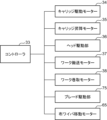
- Control configuration 12 is a block diagram showing part of the control configuration of the printer 1.
- the printer 1 includes a controller 33, a carriage drive motor 34, a carriage lift motor 35, a head drive unit 36, a work transport motor 37, a work take-up motor 38, a blade drive unit 75, and the cloth wiper movement motor 65 described above, whose operations are controlled by the controller 33.
- the carriage drive motor 34 generates a driving force to move the carriage 3 left and right between the blade wipe area 13 and the fabric wipe area 14 through the printing area 12.
- the carriage drive motor 34 corresponds to the linear motor 16 shown in FIG. 1.
- the carriage lift motor 35 generates a driving force to move the carriage 3 up and down in the blade wipe area 13 and the fabric wipe area 14.
- the head drive unit 36 executes the ejection operation of the ink, pre-treatment liquid, and post-treatment liquid from each of the heads 4, 5, and 6.
- the work transport motor 37 is a motor that serves as a driving source to transport the work W in the transport direction F in the printer 1.
- the drive motors of the transport roller 25, the drive roller 201 of the transport unit 20, and the like correspond to the work transport motor 37.
- the work winding motor 38 is a motor that serves as a driving source to rotate the winding roller 22 that winds up the work W after printing.
- the blade driving unit 75 operates the blade wiper device 7 to perform maintenance including purging of the heads 4, 5, and 6 and blade cleaning. Specifically, the blade driving unit 75 ejects high-pressure ink, pre-treatment liquid, and post-treatment liquid from the heads 4, 5, and 6 as a purging process to clean the nozzles. Also, as a blade cleaning process, the blades 72, 73, and 74 of the blade wipe unit 70 are moved in close proximity to the nozzle arrangement surfaces 40 of the heads 4, 5, and 6 in the case of non-contact wiping, which will be described later, and in contact with the nozzle arrangement surfaces 40 in the case of contact wiping.
- the cloth wiper movement motor 65 moves the moving plate 61 on which the cloth wipe unit 80 is mounted, and performs cloth wipe cleaning of the ink head 4.
- the controller 33 sets a cleaning sequence for the nozzle arrangement surface 40 by the cloth wipe unit 80, and controls the cloth wiper movement motor 65 and the carriage drive motor 34, etc., based on the cleaning sequence.
- the controller 33 is made up of a processor that operates according to a program, and generally controls the operation of each part of the printer 1. With regard to cleaning control of the heads 4, 5, and 6, the controller 33 controls the blade wiping device 7 (first wiping device) and the cloth wiping device 8 (second wiping device) to perform the required blade cleaning and cloth wiping cleaning.
- the controller 33 executes a two-stage wiping in which the nozzle arrangement surface 40 is wiped by both the blade wiper device 7 and the cloth wiper device 8.
- the wiping order is that the blade wiper device 7 first wipes the nozzle arrangement surface 40, and then the cloth wiper device 8 wipes the nozzle arrangement surface 40.
- the controller 33 sequentially executes a first wiping in which the ink blade 72 does not contact the nozzle arrangement surface 40, and a second wiping in which the ink blade 72 contacts the nozzle arrangement surface 40.
- the controller 33 wipes the nozzle arrangement surface 40 only by the blade wiper device 7.
- the controller 33 executes a purge in which the ink and the treatment liquid are forcibly ejected from the heads 4, 5, and 6 before the blade cleaning by the blade wiper device 7.
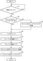
- FIG. 13 is a flowchart showing an example of the cleaning operation of the heads 4, 5, and 6 in the printer 1.
- the controller 33 judges whether or not the current time is the timing for cleaning (step S1). Whether or not it is the timing for cleaning is judged by referring to the accumulated printing time and printing area since the previous head cleaning, the number of operating days, and the like. Note that whether or not it is the timing for cleaning may be judged by considering not only the periodic factors listed above, but also non-periodic factors such as when high density printing is performed continuously or when a non-ejecting head is detected. If it is not the timing for cleaning (NO in step S1), the controller 33 puts the blade wiper device 7 and the cloth wiper device 8 into a standby state.
- step S1 If it is time for cleaning (YES in step S1), it is determined whether the carriage 3 is in the blade wipe area 13 (step S2). If the carriage 3 is not in the blade wipe area 13 (NO in step S2), the controller 33 controls the carriage drive motor 34 to move the carriage 3 to the blade wipe area 13 (step S3).
- the controller 33 executes blade cleaning.
- the controller 33 controls the blade drive unit 75 to first execute a purge that forcibly ejects ink and treatment liquid from the heads 4, 5, and 6 (step S4).
- the role of the purge is to expel air bubbles trapped in each nozzle of the heads 4, 5, and 6, and to blow away solid matter adhering to the nozzle arrangement surface 40 with the purge flow.
- the ink purge flow also softens solid matter derived from the ink, making it easier to peel off.
- the purge amount can be set in the range of about 3 ml to 60 ml per head. It is also possible to execute purging only on the ink head 4. Also, if only a specific ink head 4 has a clogged nozzle, it is also possible to execute purging on only that specific head. In this case, to prevent adverse effects on the heads (damage to the water-repellent film) due to empty wiping, it is desirable to eject a small amount (about 0.2 ml to 1.0 ml) of ink or treatment liquid from heads other than the specific ink head 4.
- the controller 33 causes the blade wipe unit 70 to perform a non-contact wipe (first wipe) of the heads 4, 5, and 6 (step S5).
- a gap of about 0.2 mm to 0.8 mm is provided between the blade body 721 of the ink blade 72 and the nozzle arrangement surface 40 of the ink head 4, and the wiping operation is performed.
- the controller 33 controls the carriage lift motor 35 to lower the carriage 3 so that the gap is formed.
- This non-contact wipe wipes away droplets hanging from the nozzle arrangement surface 40 of the heads 4, 5, and 6 after purging.
- the movement speed of the blade wipe unit 70 in the non-contact wipe can be selected from a range of about 10 mm/s to 100 mm/s.
- FIG. 16 is a front view showing the overall configuration of an inkjet printer 1A according to a modified embodiment.
- a right frame 112A is disposed on the right side of the printing area 12, defining the maintenance area 13A.
- the maintenance area 13A contains a blade wipe device 7 and a fabric wipe device 8. That is, with the printer 1A, both blade cleaning and fabric wipe cleaning can be performed in the maintenance area 13A.
Landscapes
- Ink Jet (AREA)
Abstract
インクジェット式プリンターは、処理液を吐出する処理液ヘッドと、インクを吐出するインクヘッドと、前記処理液ヘッドのノズル配置面を払拭する第1払拭部材と、前記インクヘッドのノズル配置面を払拭する、前記第1払拭部材とは異なる第2払拭部材と、を備える。
Description
本開示は、処理液を吐出する処理液ヘッドと、インクを吐出するインクヘッドとを有するインクジェット式プリンター、並びに、前記処理液ヘッドおよび前記インクヘッドを有するヘッドユニットの清掃方法に関する。
インクジェット式プリンターは、インクや所定の処理液を吐出する多数のノズルを有するヘッドを備える。このようなヘッドにおいては、前記ノズルの目詰まり解消やノズル配置面の汚れ等の除去のため、所定のタイミングで前記ノズル配置面を清掃する必要がある。
特許文献1には、処理液吐出ノズルおよびインク吐出ノズルを備えた1つのヘッドのノズル配置面を、押圧部材で支持された払拭部材で清掃するインクジェット式プリンターが開示されている。特許文献2には、ヘッドのノズル配置面を異なる払拭部材;多孔質部材のワイプブレードと弾性部材のワイプブレードとで清掃するインクジェット式プリンターが開示されている。
本開示の一の局面に係るインクジェット式プリンターは、処理液を吐出する処理液ヘッドと、インクを吐出するインクヘッドと、前記処理液ヘッドのノズル配置面を払拭する第1払拭部材と、前記インクヘッドのノズル配置面を払拭する、前記第1払拭部材とは異なる第2払拭部材と、を備える。
本開示の他の局面に係るヘッドユニットの清掃方法は、処理液を吐出する処理液ヘッドと、インクを吐出するインクヘッドとを有するヘッドユニットの清掃方法であって、前記処理液ヘッドのノズル配置面を第1払拭部材で払拭し、前記インクヘッドのノズル配置面を、前記第1払拭部材とは異なる第2払拭部材で払拭する。
以下、図面を参照しつつ、本開示の一実施形態について説明する。本実施形態では、本開示のインクジェット式プリンターとして、広幅で長尺の記録媒体に画像形成用のインクを吐出するインクヘッドを備えたプリンターを例示する。本開示のヘッドユニットの清掃方法は、当該プリンターが備えるヘッドユニットに適用される例を示す。本実施形態のインクジェット式プリンターは、織物や編物等の生地からなる記録媒体(ワーク)に、文字類や模様等の画像をインクジェット方式で印刷するデジタル捺染印刷に好適である。もちろん、本開示に係るインクジェット式プリンターおよび清掃方法は、紙シートや樹脂シート等の記録媒体に各種のインクジェット画像を印刷する用途にも用いることができる。
[インクジェット式プリンターの全体構成]
先ず、本開示の一実施形態に係るインクジェット式プリンター1の全体構成について説明する。図1は、実施形態に係るインクジェット式プリンター1の全体構成を示す正面図、図2は、図1のII-II線の模式的な断面図である。図1、図2および後出の図において、上下、前後、左右の方向表示が付されているが、これらは単に説明の便宜のためであり、方向を限定する趣旨ではない。
先ず、本開示の一実施形態に係るインクジェット式プリンター1の全体構成について説明する。図1は、実施形態に係るインクジェット式プリンター1の全体構成を示す正面図、図2は、図1のII-II線の模式的な断面図である。図1、図2および後出の図において、上下、前後、左右の方向表示が付されているが、これらは単に説明の便宜のためであり、方向を限定する趣旨ではない。
インクジェット式プリンター1は、広幅且つ長尺のワークWにインクジェット方式で画像を印刷するプリンターであって、装置フレーム10と、この装置フレーム10に組み込まれたワーク搬送部2およびキャリッジ3と、装置フレーム10の前方に配置された乾燥機19とを含む。なお、図1には乾燥機19の記載は省かれている。本実施形態では、左右方向がワークWに対して印刷を行う際の主走査方向、後方から前方に向かう方向が副走査方向であってワークWの搬送方向Fである。
装置フレーム10は、インクジェット式プリンター1の各種構成部材を搭載するための骨組みを形成している。ワーク搬送部2は、インクジェット印刷処理が行われる印刷エリアをワークWが、後方から前方に向かう搬送方向Fに進行するように、当該ワークWを間欠送りする機構である。キャリッジ3は、インクヘッド4、前処理ヘッド5、後処理ヘッド6および図略のサブタンクを搭載し、前記インクジェット印刷処理の際に左右方向に往復移動する。
装置フレーム10は、中央フレーム111、右フレーム112及び左フレーム113を含む。中央フレーム111は、インクジェット式プリンター1の各種構成部材を搭載するための骨組みを形成しており、ワーク搬送部2に応じた左右幅を有している。右フレーム112及び左フレーム113は、それぞれ中央フレーム111の右隣、左隣に立設されている。右フレーム112と左フレーム113との間が、ワークWに対して印刷処理が実行される印刷エリア12である。印刷エリア12は、ワークWの搬送方向Fと直交する幅方向、つまり主走査方向にキャリッジ3が往復移動する領域である。
右フレーム112は、ブレードワイプエリア13を形成する。ブレードワイプエリア13は、前記印刷処理が実行されないときキャリッジ3を退避させるエリアでもあって、メンテナンスのため、ヘッド4、5、6のパージ処理と、キャリッジ3の下面3Aに表出するヘッド4、5、6のノズル配置面40(図7、図14A~図14C)のブレード清掃とが所要のタイミングで行われるエリアである。ブレードワイプエリア13には、前記ブレード清掃を実行するブレードワイプ装置7(第1ワイプ装置)が配置されている。ブレードワイプ装置7は、ノズル配置面40を払拭するブレードBL(第1払拭部材)を有するブレードワイプユニット70を含む。実際には、キャリッジ3の下面3Aおよびノズル配置面40がブレードBLで払拭されることになる。前記パージ処理は、インクヘッド4、前処理ヘッド5および後処理ヘッド6の各ノズルからインクまたは処理液を強制吐出させる処理である。前記ブレード清掃は、上掲のヘッド4、5、6のノズル配置面40を、ブレードBLで払拭する処理である。ブレードワイプ装置7は、ヘッド4、5、6の休止時において、これらの乾燥を抑止するキャップとしての機能も果たす。
左フレーム113は、布ワイプエリア14を形成する。布ワイプエリア14は、布シートを用いてノズル配置面40を清掃する布ワイプ清掃が行われるエリアである。布ワイプエリア14には、前記布ワイプ清掃を実行する布ワイプ装置8(第2ワイプ装置)が配置されている。布ワイプ装置8は、布シートFS(第2払拭部材)を有する布ワイプユニット80を含む。なお、布ワイプエリア14は、キャリッジ3の折り返しエリアでもある。前記印刷処理において右方から左方へ印刷エリア12をスキャンしたキャリッジ3が、逆方向のスキャンを行う前に一時的に布ワイプエリア14へ入る。メンテナンス時には、キャリッジ3が布ワイプエリア14で停止され、布ワイプ装置8による布ワイプ清掃が実行される。また、布ワイプ装置8は、布ワイプエリア14に対して、比較的小さく構成されている。そのため、キャリッジ3を、布ワイプエリア14に移動させた際に、キャリッジ3の下面3A(ノズル配置面40)を目視することができる。そのため、インクジェット式プリンターのメンテナンス性を向上させることができる。
上述の通り本実施形態のインクジェット式プリンター1は、ヘッドの清掃用に、ブレードBLおよび布シートFSという異なる2種の払拭部材を備えている。これにより、インクヘッド4、前処理ヘッド5、後処理ヘッド6という異なる種類のヘッドの各々に応じた、つまり各ヘッドから吐出される液体の特性に応じた、各ノズル面の清掃が可能となる。ブレードBLによる清掃は、少なくとも前処理ヘッド5および後処理ヘッド6に適用される。布シートFSによる清掃は、インクヘッド4だけに適用される。本実施形態では、ブレードBLによる清掃は、全てのヘッド4、5、6に適用される例を示す。これらの点については、後記で詳述する。
また、ブレードワイプ装置7は、印刷エリア12の右側(一方の側部)に位置するブレードワイプエリア13、布ワイプ装置8は印刷エリア12の左側(他方の側部)に位置する布ワイプエリア14に、各々配置されている。ブレードワイプエリア13および布ワイプエリア14は、印刷エリア12を往復移動するキャリッジ3の退避空間および折り返し動作の空間として、プリンター1に本来的に必要な空間である。このような空間を利用して、ブレードワイプ装置7および布ワイプ装置8を装備させるので、異なる2種の払拭部材を具備させる場合でも、プリンター1の大型化を抑制することができる。
装置フレーム10の上部付近には、キャリッジ3に左右方向、つまり前記印刷処理における主走査方向の往復移動を行わせるための単軸ロボット15が組み付けられている。単軸ロボット15は、左右方向に延びるように、ワーク搬送部2の上方に配置されている。単軸ロボット15は、リニアモーター16と上下一対のガイドレール17とを含む。図2に示すように、リニアモーター16は、単軸ロボット15の延在方向に配設された固定子161と、ガイドレール17に沿って移動する可動子162とを含む。一対のガイドレール17は、左右方向に平行に延びており、可動子162を搭載した移動ブロック163が係合されている。キャリッジ3は、移動ブロック163に搭載され、単軸ロボット15によって左方向または右方向に移動される。
ワーク搬送部2は、印刷前のワークWを搬送方向Fへ繰り出す送り出しローラー21と、印刷後のワークWを巻き取る巻き取りローラー22と、印刷エリア12に配設される搬送ユニット20とを含む。送り出しローラー21は、印刷前のワークWの巻回体である送り出しロールWAの巻き取り軸である。巻き取りローラー22は、印刷処理後のワークWの巻回体である巻き取りロールWBの巻き取り軸である。送り出しローラー21は印刷エリア12の上流側、巻き取りローラー22は乾燥機19の下流側にそれぞれ配置されている。
送り出しローラー21と巻き取りローラー22との間であって印刷エリア12を通る経路が、ワークWの搬送経路となる。この搬送経路には、上流側から順にテンションローラー23、ワークガイド24、搬送ローラー25およびピンチローラー26、搬送ユニット20、引き剥がしローラー27、搬入ローラー28、乾燥機19および折り返しローラー29が配置されている。
テンションローラー23は、搬送ローラー25の上流側において、ワークWに所定の張力を付与する。ワークガイド24は、ワークWの搬送方向Fを上方向から前方向に変更し、ワークWを印刷エリア12へ搬入させる。搬送ローラー25は、印刷エリア12においてワークWを間欠送りする搬送力を発生する。ピンチローラー26は、搬送ローラー25と搬送ニップ部を形成している。搬送ローラー25とピンチローラー26とのペアにより、送り出しロールWAからワークWが繰り出され、当該ワークWが印刷エリア12を通過するように搬送方向Fへ間欠的に搬送される。
搬送ユニット20は、印刷エリア12においてワークWを、浮きや揺れを生じさせずに安定的に搬送させるために配置されている。搬送ユニット20は、前後方向に間隔を置いて配置された駆動ローラー201および従動ローラー202と、これらローラー201、202に架け渡された搬送ベルト203とを含む。ワークWは、搬送ベルト203の表面に密着した状態で搬送方向Fへ搬送される。ローラー201、202間であって搬送ベルト203の裏面側には、プラテン204が配置されている。印刷エリア12において、ワークWに対してインクヘッド4、前処理ヘッド5および後処理ヘッド6からインクおよび処理液がそれぞれ吐出される。
引き剥がしローラー27は、駆動ローラー201の前方斜め上に配置され、搬送ベルト203の表面に密着した状態の印刷後のワークWを、前記表面から引き剥がす役目を果たす。ワークWは、所定の引き剥がし角度となる引き剥がし部Bkで搬送ベルト203から引き剥がされ、下流側の搬入ローラー28へ送られる。引き剥がしローラー27と搬入ローラー28との間において、ワークWは弛みを持った状態となる。印刷後のワークWは、搬入ローラー28から乾燥機19へ送られる。乾燥機19は、ウェットなワークWに温風を吹き付けるなどして乾燥させる。折り返しローラー29は、乾燥後のワークWの搬送方向Fを前方向から下方向に変更し、ワークWを巻き取りローラー22へ導く。
キャリッジ3は、移動ブロック163に片持ち支持された状態で、搬送方向Fと交差する主走査方向(左右方向)に往復移動する。キャリッジ3は、上述のインクヘッド4、前処理ヘッド5、後処理ヘッド6および図略のサブタンクを搭載するキャリッジフレーム30を備える。キャリッジフレーム30は、ヘッド支持フレーム31及びバックフレーム32を含む。ヘッド支持フレーム31は、上掲のヘッド4、5、6を保持する水平板である。バックフレーム32は、ヘッド支持フレーム31の後端縁から上方に延びる垂直板である。バックフレーム32は移動ブロック163に固定されている。
[キャリッジの詳細]
キャリッジ3について、さらに説明を加える。図3は、図1に示すキャリッジ3の拡大斜視図である。図3には、ワークWの搬送方向F(副走査方向)と、キャリッジ3の移動方向である主走査方向Sとが示されている。図3では、ワークWに対して画像形成用のインクを吐出する複数のインクヘッド4と、非発色性の処理液を吐出する前処理ヘッド5および後処理ヘッド6とが、キャリッジ3に搭載されている例を示している。つまり、キャリッジ3は、本実施形態ではインクヘッド4および処理ヘッド5、6を有するヘッドユニットである。実際のキャリッジ3には、これらヘッド4、5、6に前記インク及び前記処理液を供給する複数のサブタンクも搭載される。なお、図1では簡略的に記載されているインクヘッド4が、図3ではより具体的に記載されている。
キャリッジ3について、さらに説明を加える。図3は、図1に示すキャリッジ3の拡大斜視図である。図3には、ワークWの搬送方向F(副走査方向)と、キャリッジ3の移動方向である主走査方向Sとが示されている。図3では、ワークWに対して画像形成用のインクを吐出する複数のインクヘッド4と、非発色性の処理液を吐出する前処理ヘッド5および後処理ヘッド6とが、キャリッジ3に搭載されている例を示している。つまり、キャリッジ3は、本実施形態ではインクヘッド4および処理ヘッド5、6を有するヘッドユニットである。実際のキャリッジ3には、これらヘッド4、5、6に前記インク及び前記処理液を供給する複数のサブタンクも搭載される。なお、図1では簡略的に記載されているインクヘッド4が、図3ではより具体的に記載されている。
インクヘッド4の各々は、例えばピエゾ素子を用いたピエゾ方式、加熱素子を用いたサーマル方式等の吐出方式でインク滴を吐出する多数のノズルと、このノズルにインクを導くインク通路とを備える。前処理ヘッド5および後処理ヘッド6も同様である。インクとしては、例えば、水系の溶媒、顔料及びバインダー樹脂を含む水系顔料インクを用いることができる。本実施形態における複数のインクヘッド4は、互いに異なる8色のインクを各々吐出する第1~第8インクヘッド4A~4Hを含む。
各色のインクヘッド4A~4Hは、主走査方向Sに並ぶように、キャリッジ3のヘッド支持フレーム31に搭載されている。各色のインクヘッド4A~4Hは、それぞれ2個のヘッドを有している。例えば第1インクヘッド4Aは、搬送方向Fの上流側に配置された上流側ヘッド4A1と、この上流側ヘッド4A1よりも下流側であって、主走査方向Sの左方側にシフトした位置に配置された下流側ヘッド4A2とで構成されている。他の色のインクヘッド4B~4Hも同様である。これらインクヘッド4B~4Hの各上流側ヘッドは、上流側ヘッド4A1と搬送方向Fにおいて同位置で主走査方向Sに一列に並び、また各下流側ヘッドは、下流側ヘッド4A2と搬送方向Fにおいて同位置で主走査方向Sに一列に並んでいる。
前処理ヘッド5及び後処理ヘッド6は、搬送方向Fにおいてインクヘッド4とは異なる位置に配置されている。前処理ヘッド5は、インクヘッド4の搬送方向Fの上流側に配置されている。図3では、1個の前処理ヘッド5がインクヘッド4の配列体の左端付近に配置されている例を示している。前処理ヘッド5は、第1インクヘッド4Aの上流側ヘッド4A1の左隣りであって、下流側ヘッド4A2と主走査方向Sにおいて同位置で前後に並んでいる。これに対し、後処理ヘッド6は、インクヘッド4の搬送方向Fの下流側に配置されている。図3では、1個の後処理ヘッド6がインクヘッド4の配列体の右端付近に配置されている例を示している。後処理ヘッド6は、第8インクヘッド4Hの下流側ヘッド4H2の右隣りであって、上流側ヘッド4H1と主走査方向Sにおいて同位置で前後に並んでいる。
前処理ヘッド5は、ワークWに対して所定の前処理を施すための前処理液を吐出する。前処理液は、ワークWの、まだインクヘッド4からインクが吐出されていない位置に、前処理ヘッド5から吐出される。前処理液は、ワークWに付着しても発色しない非発色性の処理液であって、例えばワークWへのインクの定着性やインク顔料の凝集性を高める機能等を発現する処理液である。このような前処理液としては、溶媒にプラス帯電するカチオン樹脂を配合した処理液を用いることができる。
後処理ヘッド6は、インクが付着したワークWに対して所定の後処理を施すための後処理液を吐出する。後処理液は、ワークWの、インクヘッド4からへインクが吐出された後の位置に、後処理ヘッド6から吐出される。後処理液は、同様にワークWに付着しても発色しない非発色性の処理液であって、インクヘッド4によりワークW上に印画されたインク画像の定着性や堅牢性、例えば擦れや削れ等に対する耐性を高める機能を発現する処理液である。このような後処理液としては、例えばシリコーン系の処理液を用いることができる。
ヘッド支持フレーム31のヘッドの配置箇所には、開口31Hが設けられている。インクヘッド4A~4F、前処理ヘッド5および後処理ヘッド6は、各々の開口31Hに嵌め込まれるように、ヘッド支持フレーム31に組み付けられている。各開口31Hからは、各ヘッド4、5、6の下端面に配置されているノズル配置面40が露出している。
以上の通り、本実施形態に係るインクジェット式プリンター1は、インクヘッド4、前処理ヘッド5及び後処理ヘッド6の3種類のヘッドが、一つのキャリッジ3に搭載されたオールインワン型のプリンターである。このプリンター1によれば、例えばデジタル捺染印刷における、生地にインクジェット印刷を行う印捺工程において、前処理液の吐出工程及び後処理液の吐出工程を一体的に実行させることができる。従って、捺染工程の簡素化、捺染装置のコンパクト化を図ることができる。
[ヘッドのメンテナンス]
上述の通り、インクジェット式プリンター1は、ヘッド4、5、6のメンテナンスのため、ブレードBLを用いてノズル配置面40(図7参照)を清掃するブレードワイプ装置7と、布シートFSを用いてノズル配置面40を清掃する布ワイプ装置8とを備える。なお、ノズル配置面40は、各ヘッド4、5、6においてインクや処理液を吐出する多数のノズル開口が所定のパターンで配列された面であり、キャリッジ3の下面3Aに表出している。上記で例示したインクと前処理液および後処理液とで相違する点は、バインダー樹脂の有無である。すなわち、インクには、発現色に応じて含有される顔料と、この顔料を結着する役目を果たすバインダー樹脂とが必須である。一方、前処理液および後処理液には顔料は含まれず、バインダー樹脂も必須ではない。顔料およびバインダー樹脂の含有の有無により、インクと前処理液および後処理液とでは液の物性が異なる。この物性の相違を考慮して、ブレードワイプ装置7と布ワイプ装置8とを適宜使い分けて、ヘッド4、5、6の清掃が行われる。
上述の通り、インクジェット式プリンター1は、ヘッド4、5、6のメンテナンスのため、ブレードBLを用いてノズル配置面40(図7参照)を清掃するブレードワイプ装置7と、布シートFSを用いてノズル配置面40を清掃する布ワイプ装置8とを備える。なお、ノズル配置面40は、各ヘッド4、5、6においてインクや処理液を吐出する多数のノズル開口が所定のパターンで配列された面であり、キャリッジ3の下面3Aに表出している。上記で例示したインクと前処理液および後処理液とで相違する点は、バインダー樹脂の有無である。すなわち、インクには、発現色に応じて含有される顔料と、この顔料を結着する役目を果たすバインダー樹脂とが必須である。一方、前処理液および後処理液には顔料は含まれず、バインダー樹脂も必須ではない。顔料およびバインダー樹脂の含有の有無により、インクと前処理液および後処理液とでは液の物性が異なる。この物性の相違を考慮して、ブレードワイプ装置7と布ワイプ装置8とを適宜使い分けて、ヘッド4、5、6の清掃が行われる。
ブレードワイプ装置7を用いたブレード清掃は、印刷時間や印刷面積、稼働日数などを基準として定期的に実行される。ブレード清掃の際には、単軸ロボット15の動作によってキャリッジ3がブレードワイプエリア13へ移動される。ブレード清掃の前に、インクヘッド4、前処理ヘッド5および後処理ヘッド6からインクまたは処理液を強制吐出させるパージが行われる。パージの後、ブレードワイプ装置7のブレードBLにより、ヘッド4、5、6のノズル配置面40に垂下している液滴を拭う非接触ワイプ(第1払拭)と、清掃ブレードをノズル配置面40に当接させて拭う接触ワイプ(第2払拭)とが行われる。なお、本実施形態では、第2払拭は、被払拭部と接触の可否の点で、第1払拭と異なっている。この接触・非接触ワイプについては、図14A~図14Cに基づき詳述する。
布ワイプ装置8を用いた布ワイプ清掃は、上記のブレード清掃の後、インクヘッド4のみを対象として実行される。つまり、前処理ヘッド5および後処理ヘッド6についてはブレードBLのみの払拭であるが、インクヘッド4については、ブレードBLでの払拭の後にさらに布シートFSでの払拭を行う二段階払拭が行われる。これは、インクヘッド4が顔料およびバインダー樹脂を含む液体(インク)を吐出するため、ブレード清掃だけでは十分にノズル面を清浄化できない場合があることによる。インクヘッド4のノズルにおいては、正確なインクの噴射やドットの形成のために、ノズル開口に所定のメニスカスが形成されることが肝要となる。ノズル詰まりが生じ、前記パージおよびブレード清掃を行ったとしても、所期のメニスカスがノズル開口に形成され難い。ブレード清掃の後に布シートFSでノズル配置面の払拭を行うことで、前記ノズル開口に適切なメニスカスを形成することが可能となる。他方、パージ後にいきなり布シートFSによる払拭を行うと、布シートFSが液滴を過度に吸って直ぐに清掃機能が損なわれるので、ブレードBLでの払拭が先に行われる。
前処理ヘッド5および後処理ヘッド6は、顔料およびバインダー樹脂を含まない液体を吐出するヘッドであるので、通常は布ワイプ清掃までは基本的には不要である。なお、上記のパージを行わず、インクヘッド4について布ワイプ清掃だけが行われる場合もある(図15に基づき後述する)。布ワイプ清掃の際には、図4に示すように、キャリッジ3が布ワイプエリア14へ移動される。
上記では、インクヘッド4および処理ヘッド5,6の双方を清掃する第1払拭部材としてブレードBLを、インクヘッド4のみを清掃する第2払拭部材として布シートFSを、それぞれ例示した。第1払拭部材の役目は、専らパージ後にヘッド4、5、6のノズル配置面40に存在する液を粗方拭い取ることにある。一方、第2払拭部材の役目は、先の払拭の後にノズル配置面40やノズル開口に残存する液を拭き取ることにある。
上掲の役目に鑑みて、第1払拭部材としては、非吸液性のワイパ、或いは空隙等が存在しない中実のワイパを用いることができる。ブレードBLは、その一例である。車窓の雨滴を拭うワイパの如く、第1払拭部材はノズル配置面40に存在する液滴を押し遣ることができれば良い。このため、第1払拭部材においては液滴を吸い取る吸液性は重要ではなく、ヘラ状の中実部材であれば良い。一般に、ヘッド4、5、6のノズル配置面40には、撥水膜がコートされる。この撥水膜を可及的に傷つけないよう、第1払拭部材としては、金属製よりも、所定の剛性を有するゴム材や樹脂材で形成された非吸液性の中実部材を用いることが望ましい。
一方、第2払拭部材としては、吸液性のワイパ、或いは多孔質のワイパであれば良い。吸液性・多孔質のワイパであれば、ノズル配置面40に残存する液滴やノズル開口の余分な液滴を吸い取ることができる。布シートFSは、その一例である。布シートFSとしては、例えば超極細繊維で織られた織布を用いることができる。泡径の小さい発泡体やスポンジ、海綿体なども、第2払拭部材として用いることができる。これらの中で、キャリッジ3の下面3Aに対して摺動抵抗が低く、吸液性にも優れる布シートFSを用いることが望ましい。このように、本実施形態では、第1払拭部材と第2払拭部材とは、構成する材料、或いはその構成が異なっている。
[ブレードワイプ装置の詳細]
続いて、ブレードワイプ装置7の具体例について、図4~図7を参照して説明する。図4は、図1に示したブレードワイプ装置7の具体例の斜視図である。ブレードワイプ装置7は、容器ユニット50およびブレードワイプユニット70を含む。図5の上段図は、ブレードワイプユニット70の平面図、図5の下段図は、キャリッジ3に搭載されたヘッド4、5、6の配置を示す平面図である。図6は、ブレードワイプユニット70が備えるインクブレード72の斜視図である。インクブレード72は、図1に示したブレードBL(第1払拭部材)に相当する。図7は、キャリッジ3およびブレードワイプユニット70の模式的な断面図である。
続いて、ブレードワイプ装置7の具体例について、図4~図7を参照して説明する。図4は、図1に示したブレードワイプ装置7の具体例の斜視図である。ブレードワイプ装置7は、容器ユニット50およびブレードワイプユニット70を含む。図5の上段図は、ブレードワイプユニット70の平面図、図5の下段図は、キャリッジ3に搭載されたヘッド4、5、6の配置を示す平面図である。図6は、ブレードワイプユニット70が備えるインクブレード72の斜視図である。インクブレード72は、図1に示したブレードBL(第1払拭部材)に相当する。図7は、キャリッジ3およびブレードワイプユニット70の模式的な断面図である。
上述の通り、ブレード清掃に際しては、ヘッド4、5、6のパージ動作が先に行われる。容器ユニット50は、前記パージ動作の際にヘッド4、5、6から吐出されるインク、前処理液及び後処理液を回収するための容器である。ブレードワイプユニット70は、ノズル配置面40のブレード清掃を実行するユニットである。
容器ユニット50は、前処理液と、インクおよび後処理液とを分別して回収する構造を備えている。前処理液は、インクの定着性やインク顔料の凝集性を高める処理液が用いられる。従って、前処理液とインクが混合すると、その混合液は凝集し、廃液タンクへの回収に支障を来すことがある。他方、後処理液は、インクと混合させても凝集等が生じない。これが、容器ユニット50における上記分別回収の理由である。
容器ユニット50は、フレーム構造体500の前方側に配置されたインク容器51および前処理液容器52と、フレーム構造体500の後方側に配置された洗浄液トレイ53とを含む。フレーム構造体500は、前後方向に延びる左右一対のサイドフレーム501と、これらサイドフレーム501の前端同士を繋ぐフロントフレーム502とを含む。フロントフレーム502には、容器ユニット50の引き出し用の取っ手503が取り付けられている。フロントフレーム502の下方からは、複数の廃液ホース504が引き出されている。この他、フレーム構造体500には、容器ユニット50の引き出しを可能とするスライダ505、電気ケーブルやホース類を収容するチェーンプロテクタ506が装備されている。
インク容器51は、前記パージ動作において、インクヘッド4および後処理ヘッド6から各々吐出されるインクおよび後処理液を回収する容器であって、その上面にインクおよび後処理液を受け入れる第1開口51Hを備えている。インク容器51は、左右方向に長い矩形の底面511と、底面511の4つの端縁から各々上方に延びる4つのテーパ面512と、第1開口51Hの周縁に形成された上端フランジ508とを含む。インク容器51は、前記ブレード清掃において、キャリッジ3の下面3Aに表出しているインクヘッド4および後処理ヘッド6のノズル配置面40(図7)から払拭されるインクおよび後処理液も回収する。
前処理液容器52は、第1開口51Hの上方の一部を覆う位置に配置されている。前処理液容器52は、前記パージ動作において、前処理ヘッド5から吐出される前処理液を回収する容器であって、その上面に前処理液を受け入れる第2開口72Hを備えている。前処理液容器52は、前記ブレード清掃において、前処理ヘッド5のノズル配置面40から払拭される前処理液も回収する。洗浄液トレイ53は、前記ブレード清掃の実行により汚濁したブレードワイプユニット70の洗浄用の洗浄液CL(図7)を回収する容器である。
容器ユニット50は、回収した液体の流通用に、オーバーフロー通路541、処理液通路542および中継通路543を備えている。オーバーフロー通路541は、インク容器51の底面511に始端開口を有し、終端側が図略の廃液容器へ向かう通路である。処理液通路542は、前処理液容器52の底面付近に始端開口を有し、終端側が前記廃液容器へ向かう通路である。中継通路543は、洗浄液トレイ53の底面に始端開口を有し、インク容器51の底面511付近に終端開口を有する通路である。
容器ユニット50の上面50Aにはキャップゴム55が取り付けられている。キャップゴム55は、インク容器51の第1開口51Hの周縁を取り囲むように配置されている。キャリッジ3は、図7の矢印A1で示すように、上下方向に移動が可能である。キャリッジ3がブレードワイプエリア13で待機モードとなるときや、プリンター1の休止時等にはキャリッジ3が下降され、ヘッド支持フレーム31の下面3Aがキャップゴム55に接面される。これにより、ヘッド4、5、6のノズル配置面40が密閉される。
洗浄液トレイ53の上方には、ブレードワイプユニット70の洗浄液CLを噴射する洗浄ユニット56が配置されている。洗浄ユニット56は、ノズル保持板561と、このノズル保持板561で保持される複数の洗浄ノズル562とを含む。洗浄ノズル562は、次述のブレードワイプユニット70のブレード72、73、74の各々に、洗浄液CLを扇形のスプレー状に放射する。洗浄ノズル562には、図略の洗浄液タンクから洗浄液ホース563を介して洗浄液CLが供給される。
ブレードワイプユニット70は、ブレード支持板71と、このブレード支持板71によって支持されるブレード群;インクブレード72、前処理液ブレード73および後処理液ブレード74とを備える。ブレードワイプユニット70は、図7の矢印A2で示すように、前後方向に移動が可能である。ブレード支持板71は、平板状の部材であり、キャリッジ3および洗浄ユニット56と、容器ユニット50との間で前後方向に移動する。インクブレード72は、下面3Aに表出しているインクヘッド4のノズル配置面40に当接した状態で後方向に移動することで、ノズル配置面40を払拭する。同様に、前処理液ブレード73および後処理液ブレード74は、それぞれ前処理ヘッド5及び後処理ヘッド6のノズル配置面40を払拭する。すなわち、ブレードワイプユニット70は、1回の後方向への移動動作によって、全てのヘッド4、5、6のノズル配置面40のワイピングを同時に行うことができる。
ブレードワイプユニット70の構造をさらに詳述する。図5の上段図には、ブレード72、73、74を保持したブレード支持板71の平面図が示されている。図5の下段図には、キャリッジ3に搭載されたヘッド4、5、6の配置と、ブレード72、73、74との対応関係が示されている。図5の下段図に示すヘッド4、5、6の配置態様は、先に図3に例示した態様と同じである。
ブレード支持板71は、短冊状の凸板711を複数備えている。複数の凸板711は、払拭時の移動方向である後方向に突出している。隣り合う凸板711の間には、前方側に窪んだ凹所712が形成されている。凸板711の端縁(後端)および凹所712の端縁には、インクヘッド4のノズル配置面40を払拭するインクブレード72が取り付けられている。凸板711の端縁に配置されたインクブレード72は、第1インクヘッド4Aの上流側ヘッド4A1用に配置されたインクブレード72A1などの、各色のインクヘッド4の上流側ヘッドの払拭用である。一方、凹所712の端縁に配置されたインクブレード72は、下流側ヘッド4A2用に配置されたインクブレード72A2などの、各色のインクヘッド4の下流側ヘッドの払拭用である。
前処理ヘッド5のノズル配置面40を払拭する前処理液ブレード73は、ブレード支持板71の他の領域よりも後方に突出した凸片714の端縁(後端)に取り付けられている。凸片714は、最も左方に位置する凸板711の後端から、さらに後方へ延出している。凸片714の前方側には、凹所712に対応する窓部715が設けられている。このように、前処理液ブレード73をブレード支持板71において最も前記移動方向に突出した箇所に配置することで、前処理液ブレード73が払拭した前処理液がブレード支持板71の他の部分に付着し難くなる。
後処理ヘッド6のノズル配置面40を払拭する後処理液ブレード74は、ブレード支持板71の右端の前方付近に取り付けられている。後処理ヘッド6は、第8インクヘッド4Hの上流側ヘッド4H1と、搬送方向Fの上流側と下流側とに並んで配置されている。このようなヘッド配置に対応して、ブレード支持板71は、その右端付近に保持片716および窓部717を備えている。保持片716は、その後端縁で上流側ヘッド4H1を払拭するインクブレード72H1を支持している。保持片716の左側に隣接する凹所712の端縁には、下流側ヘッド4H2をワイピングするインクブレード72H2が支持されている。窓部717は、保持片716の前方に配置された開口である。後処理液ブレード74は、窓部717の前側の開口縁において支持されている。
ブレード支持板71は、上述のブレード72、73、74の各々に対応付けて配置された複数の凸部713を有している。凸部713は、凸板711の後端、凹所712の基端縁、凸片714の後端、および窓部717の基端縁に各々連設されている。これら凸部713は、上面視の形状において、払拭時の移動方向に向けて突出する小突起である。ブレード72、73、74は、それぞれ対応付けられた凸部713に配置されている。このような配置とすることで、ブレード72、73、74に付着したインクや処理液がブレード支持板71に付着し難くすることができる。
図6には、図1のブレードBL(第1払拭部材)に相当するインクブレード72の詳細構造が示されている。前処理液ブレード73および後処理液ブレード74も、同様の構造を備えている。インクブレード72は、ブレード本体721、第1ホルダ722および第2ホルダ723を含む。ブレード本体721は、ノズル配置面40へ実際に当接して払拭動作を行うヘラ状の板材である。ブレード本体721の上端は、ブレード支持板71の上面から上方に突出した位置にある。
第1ホルダ722および第2ホルダ723は、ブレード本体721を挟み込んで保持する部材である。第1ホルダ722は、凸部713に設けられた凹所に嵌合されると共にネジ止め固定され、ブレード本体721の背面下部を支持している。第2ホルダ723は、ブレード本体721の前面下部に添設されている。第2ホルダ723は、一対の開口724を備え、ブレード本体721も開口724と同位置に貫通孔を備えている。一方、第1ホルダ722は一対の爪部725を備える。爪部725は、前記貫通孔及び開口724に挿通され、開口724の周縁において第2ホルダ723を係止している。この係止力によって、ブレード本体721が第1ホルダ722と第2ホルダ723とによって挟持されている。
[布ワイプ装置の詳細]
続いて、布ワイプ装置8の具体例について、図8~図11を参照して説明する。図8は、布ワイプ装置8の斜視図であって、布ワイプ清掃の状況を示す図である。布ワイプ装置8は、移動ユニット60および布ワイプユニット80を備える。図9Aは、布ワイプ装置8の左側面図、図9Bは、移動ユニット60の側面図である。図10は、布ワイプユニット80の斜視図、図11は、布ワイプユニット80が清掃姿勢とされた状態を示す図である。
続いて、布ワイプ装置8の具体例について、図8~図11を参照して説明する。図8は、布ワイプ装置8の斜視図であって、布ワイプ清掃の状況を示す図である。布ワイプ装置8は、移動ユニット60および布ワイプユニット80を備える。図9Aは、布ワイプ装置8の左側面図、図9Bは、移動ユニット60の側面図である。図10は、布ワイプユニット80の斜視図、図11は、布ワイプユニット80が清掃姿勢とされた状態を示す図である。
布ワイプユニット80は、布ワイプ用の布シートの束である布シートロールFSRを備える。移動ユニット60は、布ワイプユニット80を前後方向に移動させる。布ワイプ清掃においては、布シートロールFSRから繰り出された布シートFSによって構成されるワイプ領域8Wが、キャリッジ3の下面3Aに露呈しているインクヘッド4のノズル配置面40に押し当てた状態とされる。図8は、この押し当て状態を示し、当該状態から移動ユニット60が布ワイプユニット80を後方へ移動させることで、ワイプ領域8Wの布シートFSによってノズル配置面40が払拭される。
布ワイプユニット80は、布ワイプ清掃を実際に行うユニットである。移動ユニット60は、布ワイプユニット80を、下面3A(ノズル配置面40)を清掃する清掃位置と、前記清掃を行わない退避位置との間で移動させる。図9Aに示す布ワイプユニット80は前記退避位置に移動している状態、図11に示す布ワイプユニット80は、前記清掃位置に移動している状態である。移動ユニット60は、移動板61、直動ガイド62、ボールねじ63、ナット64、布ワイパ移動モーター65および姿勢変更ガイド66を含む。
移動板61は、側面視で略矩形の平板であり、直動ガイド62に沿って前後方向に移動可能である。移動板61には、布ワイプユニット80が搭載されている。移動板61の後端且つ上端のコーナー部付近には、左方に突出する回動ピン81Pが取り付けられている。回動ピン81Pは、布ワイプユニット80の回動軸となるピンである。布ワイプユニット80は、回動ピン81Pの軸回りに回動可能に移動板61に搭載されている。
直動ガイド62は、ガイドベース620、ガイドレール621およびブロック622を含む。ガイドベース620は、ガイドレール621、ボールねじ63、布ワイパ移動モーター65および姿勢変更ガイド66の取り付けベースとなる平板部材である。図9Aではガイドベース620の記載が省かれている。ガイドレール621は、前後方向に直線的に伸びるレールである。ブロック622は、ガイドレール621に嵌め込まれ、ガイドレール621に沿って前後方向に移動が可能である。移動板61は、ブロック622に固定されている。
ボールねじ63は、ガイドレール621と並行に前後方向に延びるように、ガイドベース620に軸支されている。ナット64はボールねじ63に螺合されるとともに、移動板61に取り付けられている。布ワイパ移動モーター65は、ボールねじ63の後端にモーター軸が連結されるよう配置され、ボールねじ63を軸回りに正回転または逆回転駆動する。ボールねじ63の回転により、ナット64が前後方向に移動し、これに伴って移動板61がガイドレール621にガイドされつつ前後方向へ移動する。
姿勢変更ガイド66は、移動板61の移動時に布ワイプユニット80の当接部812が当接する部材である。当接部812の姿勢変更ガイド66への当接位置によって、布ワイプユニット80の回動ピン81Pの軸回りの回動姿勢が変更される。姿勢変更ガイド66は、第1水平部661、第2水平部662および傾斜部663を含む。第1水平部661は、所定の高さの位置で直動ガイド62の延伸方向へ水平に延びている。第2水平部662は、第1水平部661よりも所定高さだけ高い位置であって、第1水平部661から後方に離れた位置で、前後方向に水平に延びている。傾斜部663は、高低差のある第1水平部661と第2水平部662との間を繋ぐ部分である。
布ワイプユニット80は、ベース板81、繰り出し部82、引き取り部83、押圧ローラー84、搬送ローラー85および伝達ベルト86を含む。ベース板81は、移動板61よりも大きいサイズを有する側面視で略正方形の平板である。ベース板81の右面であって後端且つ上端のコーナー部付近には、軸受ブッシュ811が突設されている。軸受ブッシュ811は、移動板61の回動ピン81Pが挿通される回転軸孔81Aを有している。ベース板81は、回動ピン81Pで軸支された軸受ブッシュ811を回動支点として、移動板61に対して回動可能である。
ベース板81の左面であって前端且つ下端のコーナー部付近には、当接部812が突設されている。当接部812は、例えば左右方向に延びる軸回りに回転自在なコロである。当接部812が配置されたコーナー部は、軸受ブッシュ811が配置されたコーナー部と対角方向に位置している。当接部812は、姿勢変更ガイド66に当接する。図9Aは、当接部812が姿勢変更ガイド66の第1水平部661に当接する状態を示しており、ベース板81は水平な姿勢を取る。図11は、当接部812が第1水平部661よりも高い位置にある第2水平部662に当接する状態を示しており、ベース板81は回動ピン81Pの軸回りに回動し、前側が持ち上がった状態となる。
ベース板81には繰り出し部82および引き取り部83が組み付けられている。繰り出し部82は、布ワイプ清掃を行う布シートFSを繰り出す。繰り出し部82は、未使用の布シートFSの巻回体である布シートロールFSRを保持する巻き出しローラー821を備える。巻き出しローラー821の回転軸には、トルクリミッター82Lが取り付けられている。引き取り部83は、布ワイプ清掃で使用された後の布シートFSを引き取る。引き取り部83は、使用後の布シートFSが巻回される巻き取りローラー831を備える。巻き取りローラー831の回転軸にも、トルクリミッター83Lが取り付けられている。
繰り出し部82と引き取り部83との間には、布シートFSによるワイプ領域8Wが設けられている。ワイプ領域8Wは、布シートロールFSRとされた長尺の布シートFSのうち、キャリッジ3の下面3Aに押し当てられ、実際にノズル配置面40の布ワイプ清掃を行う布シート部分が位置する領域である。ワイプ領域8Wには、繰り出し部82の布シートロールFSRから未使用の布シートFSが逐次繰り出される。ワイプ領域8Wで布ワイプ清掃の用に供された布シートFSは、引き取り部83に逐次引き取られる。
押圧ローラー84は、弾性を有するローラーからなり、ワイプ領域8Wにおいて布シートFSを支持している。押圧ローラー84は、ワイプ領域8Wの布シートFSを下面3Aに押し当てる役目を果たす。押圧ローラー84は、当該押圧ローラー84の一部がベース板81の上辺から上方へ突出するように、ベース板81の上辺付近で軸支されている。このような押圧ローラー84で布シートFSが下支えされることで、ワイプ領域8Wの布シートFSもまた、ベース板81の上辺から上方へ突出している。
押圧ローラー84の回転軸には、図には表れないワンウェイクラッチが取り付けられている。ワンウェイクラッチは、押圧ローラー84を布シートFSの繰り出し方向にのみ従動回転させる。押圧ローラー84の回転軸の両端には、一対のプーリー842が装着されている。押圧ローラー84は弾性変形可能なローラーであるのに対し、プーリー842は実質的に弾性変形しない硬質材料で形成されている。一対のプーリー842が下面3Aに押し当てられることで、押圧ローラー84とノズル配置面40との位置関係が決まる。従って、押圧ローラー84による布シートFSのノズル配置面40への押し込み量を、一定且つ軸方向に均一にすることができる。
布シートFSの繰り出し方向において、押圧ローラー84の上流側には第1ガイドローラー843が、下流側には第2ガイドローラー844が各々配設されている。第2ガイドローラー844の下流には搬送ローラー85、テンションローラー845が順次配置されている。搬送ローラー85は、布シートFSを、繰り出し部82からワイプ領域8Wを通して引き取り部83へ向けて送り出す。搬送ローラー85の回転軸には、ワンウェイクラッチ851が組み入れられている。テンションローラー845は、引き取り部83で巻き取られる布シートFSに張力を付与する。
搬送ローラー85の軸端には、図略のギアが取り付けられている。ベース板81が移動板61に対して軸受ブッシュ811を回動支点として回動すると、前記ギアに駆動力が与えられ、搬送ローラー85が回転する。搬送ローラー85の回転分だけ、布シートFSが下流側へ送り出される。また、搬送ローラー85の回転により、使用済みの布シートFSが引き取り部83に引き取られる。図10に示すように、搬送ローラー85と巻き取りローラー831との間には、伝達ベルト86が架け渡されている。搬送ローラー85が布ワイプユニット80の姿勢変更に応じて一定量だけ回転すると、その回転は伝達ベルト86によって巻き取りローラー831に伝達される。これにより、巻き取りローラー831が、搬送ローラー85の回転分だけ布シートFSを巻き取る。
第1ガイドローラー843と押圧ローラー84との間には、スプレーユニット87が配置されている。スプレーユニット87は、純水または洗浄成分を含む液体からなる洗浄液を吹き出すスプレーガン871を有する。スプレーユニット87は、装置フレーム10の左側板に取り付けられている。スプレーガン871は、押圧ローラー84の上流側においてワイプ領域8Wの布シートFSに洗浄液をスプレーする。布シートFSを布ワイプ清掃の直前に洗浄液で湿らせることで、ノズル配置面40の清掃効果を高めることができる。
図9Aは、布ワイプユニット80がノズル配置面40の清掃を行わない退避姿勢、図11は、ノズル配置面40の清掃を行う清掃姿勢を示している。図9Aの状態から布ワイパ移動モーター65が駆動され、移動板61が後方へ移動されると、布ワイプユニット80も後方へ移動する。姿勢変更ガイド66の第1水平部661(図9B)に当接していた当接部812は、傾斜部663に当接するようになる。当接部812が傾斜部663をせり上がることで、ベース板81は回動ピン81Pに挿通されている軸受ブッシュ811を回動支点として、前端部分が持ち上げられるように回動する。
図11は、当接部812が傾斜部663を登り切り、第2水平部662に至った状態である。当接部812は、第1水平部661と第2水平部662との高低差分だけ持ち上げられ、その持ち上げ分に応じた回転角度だけ、ベース板81は回動ピン81Pの軸回りに回動している。この回動により、ワイプ領域8Wも持ち上げられ、押圧ローラー84で下支えされた部分の布シートFSが下面3A(ノズル配置面40)に当接している。すなわち、ワイプ領域8Wの布シートFSで、下面3Aの布ワイプ清掃が可能な状態となる。
布ワイパ移動モーター65の駆動により、移動板61がさらに後方へ移動されることで、ノズル配置面40がワイプ領域8Wの布シートFSで清掃される。本実施形態では、図3に示したように、各色のインクヘッド4が前後に2列に並んでいる。また、布シートFSの幅は、主走査方向Sに並ぶ2つインクヘッド4をカバーできる幅を有している。従って、前後2列分のストロークだけ、少なくともワイプ領域8Wを移動させることが望ましい。このため、姿勢変更ガイド66の第2水平部662の前後長は、前記ストロークよりも長く設定されている。
ワイプ領域8Wを後端側まで移動させ布ワイプ清掃が完了すると、キャリッジ3が少量だけ上昇され、ワイプ領域8Wが下面3Aから離間される。その後、布ワイパ移動モーター65の駆動により、移動板61が前方へ戻される。やがて、当接部812の当接位置が第2水平部6622から傾斜部663へ、そして傾斜部663から第1水平部661へと変わる。これにより、ベース板81は回動ピン81Pの軸回りに回動し、布ワイプユニット80は水平な状態、つまり退避姿勢に戻る。しかる後、キャリッジ3が主走査方向Sへ2ヘッド分だけ移動され、次のインクヘッド4についての布ワイプ清掃が、上述の手順で繰り返される。
[制御構成]
図12は、プリンター1の制御構成の一部を示すブロック図である。プリンター1は、コントローラ33と、コントローラ33により動作が制御されるキャリッジ駆動モーター34、キャリッジ昇降モーター35、ヘッド駆動部36、ワーク搬送モーター37、ワーク巻取モーター38、ブレード駆動部75および上述の布ワイパ移動モーター65を含む。
図12は、プリンター1の制御構成の一部を示すブロック図である。プリンター1は、コントローラ33と、コントローラ33により動作が制御されるキャリッジ駆動モーター34、キャリッジ昇降モーター35、ヘッド駆動部36、ワーク搬送モーター37、ワーク巻取モーター38、ブレード駆動部75および上述の布ワイパ移動モーター65を含む。
キャリッジ駆動モーター34は、印刷エリア12を通してブレードワイプエリア13と布ワイプエリア14との間で、キャリッジ3を左右方向に移動させる駆動力を発生する。キャリッジ駆動モーター34は、図1に示すリニアモーター16に対応する。キャリッジ昇降モーター35は、ブレードワイプエリア13および布ワイプエリア14において、キャリッジ3を上下方向に移動させる駆動力を発生する。ヘッド駆動部36は、各ヘッド4、5、6からのインク、前処理液、後処理液の吐出動作を実行する。ワーク搬送モーター37は、プリンター1においてワークWを搬送方向Fへ搬送する駆動源となるモーターである。図2の例では、搬送ローラー25、搬送ユニット20の駆動ローラー201などの駆動モーターが、ワーク搬送モーター37に相当する。ワーク巻取モーター38は、印刷後のワークWを巻き取らせる巻き取りローラー22を回転させる駆動源となるモーターである。
ブレード駆動部75は、コントローラ33の制御下、ブレードワイプ装置7を動作させて、ヘッド4、5、6のパージ処理およびブレード清掃を含むメンテナンスを実行させる。具体的にはブレード駆動部75は、パージ処理として、ヘッド4、5、6から高圧のインク、前処理液および後処理液を各々吐出させ、ノズルを清浄化する。また、ブレード清掃として、ブレードワイプユニット70のブレード72、73、74を、ヘッド4、5、6のノズル配置面40に、後述する非接触ワイプのときは近接させ、接触ワイプのときは当接させた状態で移動させる。
布ワイパ移動モーター65は、コントローラ33の制御下、布ワイプユニット80が搭載された移動板61を移動させ、インクヘッド4の布ワイプ清掃を実行する。コントローラ33は、布ワイプユニット80によるノズル配置面40の清掃シーケンスを設定し、当該清掃シーケンスに基づき布ワイパ移動モーター65およびキャリッジ駆動モーター34などを制御する。
コントローラ33は、プログラムに従って動作するプロセッサー等からなり、プリンター1の各部の動作を統括的に制御する。ヘッド4、5、6の清掃制御に関し、コントローラ33は、ブレードワイプ装置7(第1ワイプ装置)および布ワイプ装置8(第2ワイプ装置)を制御して、所要のブレード清掃および布ワイプ清掃を実行させる。
コントローラ33は、インクヘッド4については、ブレードワイプ装置7および布ワイプ装置8の双方にてノズル配置面40を払拭させる二段階払拭を実行する。払拭順は、先ずブレードワイプ装置7でノズル配置面40を払拭させ、続いて布ワイプ装置8でノズル配置面40を払拭させる、という順序である。また、ブレードワイプ装置7によるインクヘッド4の払拭として、コントローラ33は、インクブレード72をノズル配置面40に接触させない第1払拭と、インクブレード72をノズル配置面40に接触させる第2払拭とを順次実行させる。一方、前処理ヘッド5および後処理ヘッド6については、コントローラ33は、ブレードワイプ装置7のみでノズル配置面40を払拭させる。なお、コントローラ33は、ブレードワイプ装置7によるブレード清掃の前には、ヘッド4、5、6からインクおよび処理液を各々強制吐出させるパージを実行させる。
[ヘッドの清掃制御の具体例]
上述したコントローラ33による清掃制御の具体的実施例を、図13および図15に示すフローチャートを参照して説明する。図13は、プリンター1におけるヘッド4、5、6の清掃動作の一例を示すフローチャートである。コントローラ33は、現時点が清掃タイミングであるか否かを判定する(ステップS1)。清掃タイミングであるか否かは、前回のヘッド清掃からの累積印刷時間や印刷面積、稼働日数などを参照して判定される。なお、先に挙げた定期的な要素だけでなく、高濃度印刷が連続して行われたとき、不吐出のヘッドが検知されたとき等、不定期的な要素も考慮して清掃タイミングであるか否かを判定しても良い。清掃タイミングではない場合(ステップS1でNO)、コントローラ33はブレードワイプ装置7および布ワイプ装置8を待機状態とする。
上述したコントローラ33による清掃制御の具体的実施例を、図13および図15に示すフローチャートを参照して説明する。図13は、プリンター1におけるヘッド4、5、6の清掃動作の一例を示すフローチャートである。コントローラ33は、現時点が清掃タイミングであるか否かを判定する(ステップS1)。清掃タイミングであるか否かは、前回のヘッド清掃からの累積印刷時間や印刷面積、稼働日数などを参照して判定される。なお、先に挙げた定期的な要素だけでなく、高濃度印刷が連続して行われたとき、不吐出のヘッドが検知されたとき等、不定期的な要素も考慮して清掃タイミングであるか否かを判定しても良い。清掃タイミングではない場合(ステップS1でNO)、コントローラ33はブレードワイプ装置7および布ワイプ装置8を待機状態とする。
清掃タイミングである場合(ステップS1でYES)、キャリッジ3がブレードワイプエリア13に存在している否かが判定される(ステップS2)。キャリッジ3がブレードワイプエリア13に存在していない場合(ステップS2でNO)、コントローラ33はキャリッジ駆動モーター34を制御して、キャリッジ3をブレードワイプエリア13へ移動させる(ステップS3)。
キャリッジ3がブレードワイプエリア13に存在している場合(ステップS2でYES)、コントローラ33はブレード清掃を実行させる。コントローラ33は、ブレード駆動部75を制御して、先ずはヘッド4、5、6からインクおよび処理液を各々強制吐出させるパージを実行させる(ステップS4)。パージの役目としては、ヘッド4、5、6の各ノズルに抱き込まれている気泡を排出すること、ノズル配置面40に付着している固形物をパージ流で吹き飛ばすこと、などが挙げられる。インクヘッド4については、インク由来の固形物をインクのパージ流で軟化させ、剥離させ易くすることも挙げられる。
パージ量は、1ヘッドあたり3ml~60ml程度の範囲に設定することができる。なお、インクヘッド4だけにパージを実行させても良い。また、特定のインクヘッド4だけにノズル詰まりが生じているような場合は、その特定ヘッドだけにパージを実行させても良い。この場合、空ワイプによるヘッドへの悪影響(撥水膜の損傷)の防止のため、前記特定のインクヘッド4以外のヘッドからも少量(0.2ml~1.0ml程度)のインクまたは処理液を吐出させることが望ましい。
次にコントローラ33は、ブレードワイプユニット70にヘッド4、5、6の非接触ワイプ(第1払拭)を実行させる(ステップS5)。非接触ワイプでは、インクブレード72のブレード本体721とインクヘッド4のノズル配置面40との間に、0.2mm~0.8mm程度のギャップを設けて払拭動作を行わせる。前処理ヘッド5および後処理ヘッド6についても同様である。コントローラ33は、前記ギャップが形成されるよう、キャリッジ昇降モーター35を制御してキャリッジ3を下降させる。この非接触ワイプにより、パージの後、ヘッド4、5、6のノズル配置面40に垂下している液滴が拭われる。非接触ワイプにおけるブレードワイプユニット70の移動速度は、10mm/s~100mm/s程度の範囲から選択することができる。
続いてコントローラ33は、ブレードワイプユニット70にヘッド4、5、6の接触ワイプ(第2払拭)を実行させる(ステップS6)。接触ワイプでは、インクブレード72のブレード本体721をインクヘッド4のノズル配置面40に押し当てて払拭動作を行わせる。前処理ヘッド5および後処理ヘッド6についても同様である。前記押し当ての押圧力(線圧)は、0.1N/m~10N/m程度に設定することができる。コントローラ33は、前記押圧力が達成させるよう、キャリッジ3を下降させる。接触ワイプにおけるブレードワイプユニット70の移動速度も、10mm/s~100mm/s程度の範囲から選択することができる。
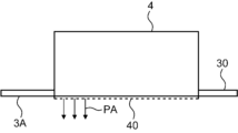
図14A~図14Cは、上記のステップS4~S6の清掃手順を模式的に示す図である。ここでは、一つのインクヘッド4と、当該ヘッド4の払拭用の一つのインクブレード72とが図示されている。図14Aは、ステップS4のパージ動作を示している。インクヘッド4のノズル配置面40からはパージ液PA、つまりインクが吐出されている。
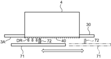
図14Bは、ステップS5の非接触ワイプの実行状況を示す図である。インクブレード72(ブレード本体721)とノズル配置面40との間には、上述のギャップが存在している。インクブレード72の搭載されているブレード支持板71が、キャリッジフレーム30に対して相対移動される。ノズル配置面40に付着している液滴DRは、インクブレード72により拭われる。
図14Cは、ステップS6の接触ワイプの実行状況を示す図である。インクブレード72はノズル配置面40に接触しており、前記押圧力によって変形した状態となる。この状態でブレード支持板71が、キャリッジフレーム30に対して相対移動される。これにより、ノズル配置面40自体が、インクブレード72により払拭される。このように非接触・接触の二段階の払拭により、ノズル配置面40が清浄化される。非接触ワイプではインクブレード72とノズル配置面40とが接触しないため、ノズル配置面40にコートされている撥水膜に影響を与えない。液滴DRの除去の全てをブレードの接触ワイプに依存すると、撥水膜がダメージを与え易い。本実施形態のように、液滴DRを拭う非接触ワイプを前置することで、ノズル配置面40のクリーニング性を高めつつ、前記撥水膜のダメージを抑制できる。
図13に戻り、ステップS4~S6のブレード清掃を終えたら、コントローラ33は、キャリッジ昇降モーター35を駆動して、ノズル配置面40がインクブレード72から離間するよう、キャリッジ3を上昇させる。引き続きコントローラ33は、キャリッジ駆動モーター34を制御して、キャリッジ3を布ワイプエリア14へ移動させる(ステップS7)。移動後、コントローラ33は、ノズル配置面40が所定の高さ位置となるよう、キャリッジ3を下降させる。続いてコントローラ33は、布ワイパ移動モーター65を駆動して、布ワイプユニット80によるインクヘッド4のノズル配置面40の布ワイプ清掃を実行させる(ステップS8)。
すなわち、移動ユニット60の移動板61がキャリッジフレーム30に対して相対移動され、布シートFSによりノズル配置面40の払拭が行われる。この払拭の前に、布シートFSにはスプレーユニット87から洗浄液が噴霧される。洗浄液には、ノズル配置面40の撥水膜の保護のため、表面張力を落とす界面活性剤を配合することが望ましい。押圧ローラー84による布シートFSのノズル配置面40への押圧力は、0.02N/mm2~0.20N/mm2、より好ましくは、0.05N/mm2~0.15N/mm2の範囲で設定することができる。布シートFSの相対移動速度は、10mm/s~100mm/s程度の範囲から選択することができる。
図13に示した制御は、ヘッド4、5、6のパージ、ブレード72、73、74によるヘッド4、5、6の非接触・接触払拭、および布シートFSによるインクヘッド4の払拭という順序で行われる、言わば「フルワイプ動作」である。常に、このフルワイプ動作を行わせる必要はなく、所要時にだけフルワイプ動作を実行させても良い。
図15は、フルワイプ動作を選択的に実行させる制御例を示すフローチャートである。コントローラ33は、プリンター1の現状モードが「通常モード」であるか否かを確認する(ステップS11)。「通常モード」は、不吐出ノズルの発生等のアクシデントが検出されたり、高濃度印刷が連続して行われたりする事象が生じていない状態である。「通常モード」では、定期的にインクヘッド4の布ワイプ清掃だけが行われるものとする。
「通常モード」である場合(ステップS11でYES)、コントローラ33は、現時点が清掃タイミングであるか否かを判定する(ステップS12)。清掃タイミングである場合(ステップS12でYES)、コントローラ33は、キャリッジ3を布ワイプエリア14へ移動させるとともに、布ワイプ装置8を動作させて布シートFSによるインクヘッド4の払拭を行わせる(ステップS13)。清掃タイミングではない場合(ステップS12でNO)、コントローラ33はブレードワイプ装置7および布ワイプ装置8を待機状態とする。
これに対し、「通常モード」ではない場合(ステップS11でNO)、コントローラ33は、ブレードワイプ装置7および布ワイプ装置8を適時に動作させて、図13に例示したような「フルワイプ動作」を実行させる(ステップS14)。なお、インクヘッド4に不吐出ノズルが発生した場合には、当該インクヘッド4に対して布ワイプ装置8にて布ワイプ清掃を先ずは実行させ、不吐出が回復しない場合に「フルワイプ動作」を実行させるというシーケンスを設定しても良い。
[プリンターの変形実施形態]
図1に示すプリンター1では、印刷エリア12の右側に位置するブレードワイプエリア13にブレードワイプ装置7を、左側に位置する布ワイプエリア14に布ワイプ装置8を、それぞれ配置する例を示した。この配置に代えて、ブレードワイプ装置7および布ワイプ装置8のいずれも、印刷エリア12の一方の側部に配置するレイアウトとしても良い。
図1に示すプリンター1では、印刷エリア12の右側に位置するブレードワイプエリア13にブレードワイプ装置7を、左側に位置する布ワイプエリア14に布ワイプ装置8を、それぞれ配置する例を示した。この配置に代えて、ブレードワイプ装置7および布ワイプ装置8のいずれも、印刷エリア12の一方の側部に配置するレイアウトとしても良い。
図16は、変形実施形態に係るインクジェット式プリンター1Aの全体構成を示す正面図である。印刷エリア12の右側には、メンテナンスエリア13Aを区画する右フレーム112Aが配置されている。メンテナンスエリア13Aには、ブレードワイプ装置7および布ワイプ装置8が収容されている。すなわち、プリンター1Aでは、ブレード清掃および布ワイプ清掃の双方が、メンテナンスエリア13Aにおいて実行可能である。
図1のプリンター1のレイアウトでは、キャリッジ3の往復移動のために必要な印刷エリア12の左右の領域を、ブレードワイプエリア13および布ワイプエリア14として各々活用するので、プリンター1の小型化を図れる利点がある。しかし、ブレードワイプエリア13でのブレード清掃の後、キャリッジ3を布ワイプエリア14へ移動させた上で、布ワイプ清掃を実行させる必要が生じる。一方、変形実施形態のプリンター1Aによれば、メンテナンスエリア13Aにおいて、キャリッジ3を僅かに移動させるだけで、ブレード清掃および布ワイプ清掃の双方を行える。従って、メンテナンス時間を短縮することが可能となる。また、ヘッド清掃に必要な付属品、例えば洗浄液の供給配管、廃液配管、タンク類などをメンテナンスエリア13A付近に集約でき、付属品の配置を簡素化・効率化できる利点もある。
この他、本開示のプリンターは種々の変形実施形態を取ることができる。上記実施形態では、第1払拭部材がブレードBL、第2払拭部材が布シートFSという、払拭部材の構成材料が異なる例を示した。第1払拭部材と第2払拭部材とが「異なる」という意味は、多義的である。例えば、(1)払拭方法が異なる、(2)払拭部材が同一または類似材料であるが特性が異なる、などを例示できる。上記(1)の例としては、ノズル配置面に対して接触または非接触とする、払拭速度や押圧力を異ならせる、などを例示できる。上記(2)の例としては、吸液性、撥水性、剛性を異ならせる、などを例示できる。上記(1)と(2)とを組み合わせて「異なる」を実現しても良い。さらに、上記実施形態では、インクヘッド4については、ブレードBLおよび布シートFSでの払拭を行う例を示した。同一の払拭部材で複数回の払拭を行うのではなく、「異なる」払拭部材を用いて複数回の払拭を行う限りにおいて、各種の払拭部材の組み合わせを採用することができる。
1 インクジェット式プリンター
12 印刷エリア
13 ブレードワイプエリア(一方の側部)
14 布ワイプエリア(他方の側部)
3 キャリッジ(ヘッドユニット)
33 コントローラ
4 インクヘッド
40 ノズル配置面
5 前処理ヘッド(処理液ヘッド)
6 後処理ヘッド(処理液ヘッド)
7 ブレードワイプ装置(第1ワイプ装置)
70 ブレードワイプユニット
72 インクブレード(ブレード)
73 前処理液ブレード(ブレード)
74 後処理液ブレード(ブレード)
8 布ワイプ装置(第2ワイプ装置)
80 布ワイプユニット
BL ブレード(第1払拭部材)
FS 布シート(第2払拭部材)
W ワーク(記録媒体)
12 印刷エリア
13 ブレードワイプエリア(一方の側部)
14 布ワイプエリア(他方の側部)
3 キャリッジ(ヘッドユニット)
33 コントローラ
4 インクヘッド
40 ノズル配置面
5 前処理ヘッド(処理液ヘッド)
6 後処理ヘッド(処理液ヘッド)
7 ブレードワイプ装置(第1ワイプ装置)
70 ブレードワイプユニット
72 インクブレード(ブレード)
73 前処理液ブレード(ブレード)
74 後処理液ブレード(ブレード)
8 布ワイプ装置(第2ワイプ装置)
80 布ワイプユニット
BL ブレード(第1払拭部材)
FS 布シート(第2払拭部材)
W ワーク(記録媒体)
Claims (15)
- 処理液を吐出する処理液ヘッドと、
インクを吐出するインクヘッドと、
前記処理液ヘッドのノズル配置面を払拭する第1払拭部材と、
前記インクヘッドのノズル配置面を払拭する、前記第1払拭部材とは異なる第2払拭部材と、を備えるインクジェット式プリンター。 - 請求項1に記載のインクジェット式プリンターにおいて、
前記第1払拭部材がブレードであり、前記第2払拭部材が布シートである、インクジェット式プリンター。 - 請求項1に記載のインクジェット式プリンターにおいて、
前記第1払拭部材が非吸液性のワイパであり、前記第2払拭部材が吸液性のワイパである、インクジェット式プリンター。 - 請求項1に記載のインクジェット式プリンターにおいて、
前記第1払拭部材が中実のワイパであり、前記第2払拭部材が多孔質のワイパである、インクジェット式プリンター。 - 請求項1~4のいずれか1項に記載のインクジェット式プリンターにおいて、
前記第1払拭部材を有する第1ワイプ装置と、
前記第2払拭部材を有する第2ワイプ装置と、
前記第1ワイプ装置および前記第2ワイプ装置を制御するコントローラと、を備え、
前記コントローラは、前記第1ワイプ装置および前記第2ワイプ装置で前記インクヘッドのノズル配置面を払拭させ、前記第1ワイプ装置のみで前記処理液ヘッドのノズル配置面を払拭させる制御を実行する、インクジェット式プリンター。 - 請求項5に記載のインクジェット式プリンターにおいて、
前記コントローラは、前記インクヘッドのノズル配置面を前記第1ワイプ装置で払拭させ、続いて前記第2ワイプ装置で払拭させる制御を実行する、インクジェット式プリンター。 - 請求項6に記載のインクジェット式プリンターにおいて、
前記コントローラは、前記インクヘッドのインク吐出動作をさらに制御するものであって、前記インクヘッドからインクを強制吐出するパージを実行させた後、前記第1ワイプ装置での払拭および前記第2ワイプ装置での払拭を順次実行させる、インクジェット式プリンター。 - 請求項1~4のいずれか1項に記載のインクジェット式プリンターにおいて、
前記処理液ヘッドおよび前記インクヘッドを搭載するキャリッジと、
インクジェット印刷される記録媒体の搬送領域であって、前記キャリッジがインクジェット印刷処理のため前記記録媒体の搬送方向と直交する幅方向に往復移動する印刷エリアと、
前記第1払拭部材を有する第1ワイプ装置と、
前記第2払拭部材を有する第2ワイプ装置と、を備え、
前記第1ワイプ装置は、前記印刷エリアの一方の側部に、前記第2ワイプ装置は、前記印刷エリアの他方の側部に、それぞれ配置されている、インクジェット式プリンター。 - 請求項1~4のいずれか1項に記載のインクジェット式プリンターにおいて、
前記処理液ヘッドおよび前記インクヘッドを搭載するキャリッジと、
インクジェット印刷される記録媒体の搬送領域であって、前記キャリッジがインクジェット印刷処理のため前記記録媒体の搬送方向と直交する幅方向に往復移動する印刷エリアと、
前記第1払拭部材を有する第1ワイプ装置と、
前記第2払拭部材を有する第2ワイプ装置と、を備え、
前記第1ワイプ装置および前記第2ワイプ装置は、いずれも前記印刷エリアの一方の側部に配置されている、インクジェット式プリンター。 - 処理液を吐出する処理液ヘッドと、インクを吐出するインクヘッドとを有するヘッドユニットの清掃方法であって、
前記処理液ヘッドのノズル配置面を第1払拭部材で払拭し、
前記インクヘッドのノズル配置面を、前記第1払拭部材とは異なる第2払拭部材で払拭する、ヘッドユニットの清掃方法。 - 請求項10に記載のヘッドユニットの清掃方法において、
前記第1払拭部材としてブレードを用い、前記第2払拭部材として布シートを用いる、ヘッドユニットの清掃方法。 - 請求項10または11に記載のヘッドユニットの清掃方法において、
前記処理液ヘッドのノズル配置面は、第1払拭部材のみの払拭とし、
前記インクヘッドのノズル配置面は、前記第1払拭部材で払拭した後に、前記第2払拭部材で払拭する二段階払拭とする、ヘッドユニットの清掃方法。 - 請求項12に記載のヘッドユニットの清掃方法において、
前記インクヘッドの前記第1払拭部材による払拭は、前記第1払拭部材を前記ノズル配置面に接触させない第1払拭と、前記第1払拭部材を前記ノズル配置面に接触させる第2払拭と、を含む、ヘッドユニットの清掃方法。 - 請求項12に記載のヘッドユニットの清掃方法において、
前記インクヘッドの前記第1払拭部材による払拭は、
前記第1払拭部材を前記ノズル配置面に接触させない第1払拭と、
前記第1払拭の後に行われる、前記第1払拭部材を前記ノズル配置面に接触させる第2払拭と、を含み、
前記第2払拭の後に、前記第2払拭部材として布シートを用いた払拭を行う、
ヘッドユニットの清掃方法。 - 請求項14に記載のヘッドユニットの清掃方法において、
前記第1払拭の前に、前記インクヘッドからインクを強制吐出するパージを実行させる、ヘッドユニットの清掃方法。
Priority Applications (5)
| Application Number | Priority Date | Filing Date | Title |
|---|---|---|---|
| CN202480036196.1A CN121219138A (zh) | 2023-06-06 | 2024-06-06 | 喷墨式打印机及头单元的清扫方法 |
| EP24819386.4A EP4696512A1 (en) | 2023-06-06 | 2024-06-06 | Ink jet printer and method for cleaning head unit |
| PCT/JP2024/020698 WO2024253158A1 (ja) | 2023-06-06 | 2024-06-06 | インクジェット式プリンターおよびヘッドユニットの清掃方法 |
| JP2025502680A JP7704997B2 (ja) | 2023-06-06 | 2024-06-06 | インクジェット式プリンターおよびヘッドユニットの清掃方法 |
| JP2025105808A JP2025128396A (ja) | 2023-06-06 | 2025-06-23 | インクジェット式プリンターおよびヘッドユニットの清掃方法 |
Applications Claiming Priority (2)
| Application Number | Priority Date | Filing Date | Title |
|---|---|---|---|
| JP2023-092878 | 2023-06-06 | ||
| JP2023092878 | 2023-06-06 |
Publications (1)
| Publication Number | Publication Date |
|---|---|
| WO2024252720A1 true WO2024252720A1 (ja) | 2024-12-12 |
Family
ID=93795787
Family Applications (1)
| Application Number | Title | Priority Date | Filing Date |
|---|---|---|---|
| PCT/JP2024/002062 Ceased WO2024252720A1 (ja) | 2023-06-06 | 2024-01-24 | インクジェット式プリンターおよびヘッドユニットの清掃方法 |
Country Status (1)
| Country | Link |
|---|---|
| WO (1) | WO2024252720A1 (ja) |
Citations (6)
| Publication number | Priority date | Publication date | Assignee | Title |
|---|---|---|---|---|
| JPH09254400A (ja) * | 1996-03-26 | 1997-09-30 | Canon Inc | インクジェット記録装置 |
| JP2004330750A (ja) * | 2003-05-12 | 2004-11-25 | Seiko Epson Corp | 液体噴射ヘッド及び液体噴射装置 |
| JP2008143039A (ja) * | 2006-12-11 | 2008-06-26 | Fuji Xerox Co Ltd | 液滴吐出装置 |
| JP2010221713A (ja) * | 2004-07-14 | 2010-10-07 | Seiko Epson Corp | 液体噴射装置および液体払拭装置 |
| JP2019030990A (ja) * | 2017-08-07 | 2019-02-28 | セイコーエプソン株式会社 | 液体噴射装置 |
| JP2023048762A (ja) * | 2021-09-28 | 2023-04-07 | 京セラドキュメントソリューションズ株式会社 | ワイピング装置並びに画像形成装置およびワイピング方法 |
-
2024
- 2024-01-24 WO PCT/JP2024/002062 patent/WO2024252720A1/ja not_active Ceased
Patent Citations (6)
| Publication number | Priority date | Publication date | Assignee | Title |
|---|---|---|---|---|
| JPH09254400A (ja) * | 1996-03-26 | 1997-09-30 | Canon Inc | インクジェット記録装置 |
| JP2004330750A (ja) * | 2003-05-12 | 2004-11-25 | Seiko Epson Corp | 液体噴射ヘッド及び液体噴射装置 |
| JP2010221713A (ja) * | 2004-07-14 | 2010-10-07 | Seiko Epson Corp | 液体噴射装置および液体払拭装置 |
| JP2008143039A (ja) * | 2006-12-11 | 2008-06-26 | Fuji Xerox Co Ltd | 液滴吐出装置 |
| JP2019030990A (ja) * | 2017-08-07 | 2019-02-28 | セイコーエプソン株式会社 | 液体噴射装置 |
| JP2023048762A (ja) * | 2021-09-28 | 2023-04-07 | 京セラドキュメントソリューションズ株式会社 | ワイピング装置並びに画像形成装置およびワイピング方法 |
Similar Documents
| Publication | Publication Date | Title |
|---|---|---|
| EP3530466B1 (en) | Wiping device, head maintenance device, and liquid discharge apparatus | |
| JP6044307B2 (ja) | 液体噴射装置 | |
| JP5352409B2 (ja) | クリーナカートリッジ及びクリーニング装置並びに画像形成装置 | |
| JP5259458B2 (ja) | インクジェット記録装置及び記録ヘッドのメンテナンス方法 | |
| US10457053B2 (en) | Ink jet printer | |
| JP2017052117A (ja) | 液体噴射装置及びクリーニング装置 | |
| JP6194576B2 (ja) | 液体噴射装置 | |
| JP2018079684A (ja) | ヘッド清掃装置、ヘッドメンテナンス装置、液体を吐出する装置 | |
| US20030081050A1 (en) | Inkjet printer cartridge adapted for enhanced cleaning thereof and method of assembling the printer cartridge | |
| JP2025065513A (ja) | インクジェット記録装置 | |
| JP6418207B2 (ja) | 液体噴射装置 | |
| JP2012051132A (ja) | インクジェット記録装置 | |
| JP2017071135A (ja) | クリーニング装置およびそれを備えたインクジェットプリンタ | |
| JP3018646B2 (ja) | インクジェット印刷装置のヘッドクリーニング装置 | |
| JP7704997B2 (ja) | インクジェット式プリンターおよびヘッドユニットの清掃方法 | |
| WO2024252720A1 (ja) | インクジェット式プリンターおよびヘッドユニットの清掃方法 | |
| JP2015085618A (ja) | インクジェット記録装置 | |
| JP3897453B2 (ja) | インクジェット記録装置 | |
| JP3166518B2 (ja) | インクジェット装置及びワイピング部材 | |
| JP4536858B2 (ja) | インクジェットプリンタ | |
| JP2010012739A (ja) | 液体吐出記録装置及びインクジェット記録装置 | |
| JP4408485B2 (ja) | インクジェットプリンタにおけるワイピング装置 | |
| JP6474684B2 (ja) | 液体払拭装置及び液体払拭方法 | |
| JP4368465B2 (ja) | インクジェットプリンタ | |
| WO2024202999A1 (ja) | ノズル配置面の清掃装置および清掃方法 |
Legal Events
| Date | Code | Title | Description |
|---|---|---|---|
| 121 | Ep: the epo has been informed by wipo that ep was designated in this application |
Ref document number: 24818959 Country of ref document: EP Kind code of ref document: A1 |
|
| NENP | Non-entry into the national phase |
Ref country code: DE |