WO2024252727A1 - Appareil de détection de gaz - Google Patents
Appareil de détection de gaz Download PDFInfo
- Publication number
- WO2024252727A1 WO2024252727A1 PCT/JP2024/004634 JP2024004634W WO2024252727A1 WO 2024252727 A1 WO2024252727 A1 WO 2024252727A1 JP 2024004634 W JP2024004634 W JP 2024004634W WO 2024252727 A1 WO2024252727 A1 WO 2024252727A1
- Authority
- WO
- WIPO (PCT)
- Prior art keywords
- detection chamber
- intake
- exhaust
- gas
- hole
- Prior art date
- Legal status (The legal status is an assumption and is not a legal conclusion. Google has not performed a legal analysis and makes no representation as to the accuracy of the status listed.)
- Ceased
Links
Images


Classifications
-
- G—PHYSICS
- G01—MEASURING; TESTING
- G01N—INVESTIGATING OR ANALYSING MATERIALS BY DETERMINING THEIR CHEMICAL OR PHYSICAL PROPERTIES
- G01N29/00—Investigating or analysing materials by the use of ultrasonic, sonic or infrasonic waves; Visualisation of the interior of objects by transmitting ultrasonic or sonic waves through the object
- G01N29/02—Analysing fluids
- G01N29/036—Analysing fluids by measuring frequency or resonance of acoustic waves
-
- G—PHYSICS
- G01—MEASURING; TESTING
- G01N—INVESTIGATING OR ANALYSING MATERIALS BY DETERMINING THEIR CHEMICAL OR PHYSICAL PROPERTIES
- G01N29/00—Investigating or analysing materials by the use of ultrasonic, sonic or infrasonic waves; Visualisation of the interior of objects by transmitting ultrasonic or sonic waves through the object
- G01N29/22—Details, e.g. general constructional or apparatus details
- G01N29/24—Probes
Definitions
- smell identification relies on the experience and senses of on-site workers, leading to increased management costs and training costs.
- the photoacoustic effect is a phenomenon in which, when light of a specific wavelength (such as laser light) is intermittently (pulsed) irradiated onto molecules of a specific component that makes up a gas, the molecules that absorb the light undergo thermal expansion and contraction, generating acoustic waves.
- Photoacoustic sensors are small and can detect gas components with high sensitivity, so they are being applied to a variety of manufacturing sites.
- the photoacoustic sensor works by using a microphone to detect acoustic waves that are generated when molecules that absorb light undergo thermal expansion and contraction.
- a microphone to detect acoustic waves that are generated when molecules that absorb light undergo thermal expansion and contraction.
- the photoacoustic sensor described in Patent Document 1 has only one detection cell, making it difficult to meet the demands for improved detection sensitivity and the ability to simultaneously detect multiple gas components.
- the object of the present invention is to provide a novel gas detection device that can solve at least one of the problems described above.
- the gas detection device comprises a first detection chamber and a second detection chamber with a predetermined volume, a light emitting means arranged in either or both of the first detection chamber and the second detection chamber for emitting light at a predetermined frequency, a resonance passage fluidly connecting the first detection chamber and the second detection chamber, a measurement chamber fluidly connected to the resonance passage, a microphone arranged in the measurement chamber for measuring the intensity of an acoustic wave, and an intake and exhaust mechanism for forcibly discharging gas remaining in the first detection chamber and the second detection chamber and drawing new measurement gas into the first detection chamber and the second detection chamber.
- the present invention makes it possible to improve detection sensitivity, detect multiple gas components simultaneously, and eliminate the effects of residual gas components when measuring gas components continuously.
- the gas detection device OD comprises at least a photoacoustic cell 10 and an intake and exhaust mechanism 21.
- the intake and exhaust mechanism 21 is made up of a first intake and exhaust mechanism 21A and a second intake and exhaust mechanism 21B.
- the first intake and exhaust mechanism 21A and the second intake and exhaust mechanism 21B are made up of propeller fans of the same specifications, but other types of fans can also be used.
- the intake and exhaust mechanism can also be a single intake and exhaust mechanism without being divided.
- the photoacoustic cell 10 is disposed on one side (hereinafter referred to as the front side) of a flat substrate (e.g., a resin substrate, etc.) 11, and the intake and exhaust mechanisms 21A, 21B are disposed on the other side (hereinafter referred to as the back side) of the substrate 11.
- the photoacoustic cell 10 is provided on the front side of the substrate 11 on which a control circuit, etc. is mounted.
- the substrate 11, the photoacoustic cell 10, and the intake and exhaust mechanism 21 are integrated as a whole into an assembly. This assembly can therefore be built into a box made of synthetic resin or the like and assembled into a gas detection device.
- the control circuit of the substrate 11 has the function of controlling the emission frequency and light intensity of the light emitting means described below, as well as the function of measuring acoustic waves from a microphone described below. For this reason, by arranging the photoacoustic cell 10 on the surface of the substrate 11 on which the control circuit is provided, connection wiring etc. is made easier.
- the photoacoustic sensor 10 includes a housing 12 made of a metal or resin material, and a first detection chamber 13A and a second detection chamber 13B with a predetermined volume are formed inside the housing 12.
- the first detection chamber 13A and the second detection chamber 13B are hollow spaces, and are formed with substantially the same shape and the same spatial volume.
- the spatial shape of the first detection chamber 13A and the second detection chamber 13B can be formed into a cylindrical shape or a rectangular parallelepiped shape. In this embodiment, the spatial shape is determined to be a cylindrical shape.
- a first suction hole 14A that fluidly connects the first detection chamber 13A to the outside is formed in the wall surface 12W of the housing 12 on the opposite side of the substrate 11 of the first detection chamber 13A.
- a second suction hole 14B that fluidly connects the second detection chamber 13B to the outside is formed in the wall surface 12W of the housing 12 on the opposite side of the substrate 11 of the second detection chamber 13B.
- suction holes 14A and 14B There may be one or more suction holes 14A and 14B, but what is important is that they have an suction area that allows the necessary amount of measurement gas to be smoothly introduced into the detection chambers 13A and 13B. In addition, the suction holes 14A and 14B have the same suction area.
- the outside refers to the space in which the gas to be measured exists, and corresponds to the manufacturing site or storage warehouse as described above. Therefore, the measurement gas present in the manufacturing site or storage warehouse is sucked into the first detection chamber 13A and the second detection chamber 13B through the first suction hole 14A and the second suction hole 14B.
- a first LED element 15A which is a first light emitting means, is disposed in the first detection chamber 13A, and the first LED element 15A emits light in a pulsed manner at a predetermined frequency to thermally excite a specific component of the measurement gas Gas in the first detection chamber 13A.
- the first LED element 15A is provided on the front side of the substrate 11, and is controlled and driven by a control circuit (not shown).
- a second LED element 15B which is a second light emitting means, is disposed in the second detection chamber 13B, and the second LED element 15B emits light in a pulsed manner at a predetermined frequency to thermally excite a specific component of the measurement gas Gas in the second detection chamber 13B.
- the second LED element 15B is also provided on the front side of the substrate 11, and is controlled and driven by a control circuit (not shown).
- the first detection chamber 13A and the second detection chamber 13B may detect the same gas component, or different gas components.
- the light emission frequency of each LED element 15A, 15B can be determined according to the gas component to be detected.
- a semiconductor laser or the like can also be used as the light emitting means.
- the first detection chamber 13A and the second detection chamber 13B are fluidly connected by a straight resonance passage 16 formed inside the housing 12.
- This resonance passage 16 has a circular cross section perpendicular to the axis of the resonance passage 16, and has the function of resonating and amplifying the minute photoacoustic waves generated in the first detection chamber 13A and the second detection chamber 13B. This makes it easy to measure the photoacoustic waves using a microphone, which will be described later.
- a measurement chamber 18 is formed on the side of the housing 12 that contacts the substrate 11, housing a microphone 17 that measures photoacoustic waves.
- the measurement chamber 18 is fluidly connected to the resonance passage 16 via a connection passage 19.
- the connection point between the resonance passage 16 and the connection passage 19 corresponds to the midpoint of the resonance passage 16 that is connected to the first detection chamber 13A and the second detection chamber 13B, ensuring the geometric symmetry of the first detection chamber 13A, the second detection chamber 13B, and the resonance passage 16.
- the first detection chamber 13A, the second detection chamber 13B, and the resonance passage 16 are shaped line-symmetrically on the page, with the axis of the connection passage 19 as the boundary.
- a microphone 17 for measuring the intensity of the photoacoustic wave is placed in the measurement chamber 18.
- the microphone 17 is provided on the front surface side of the substrate 11, and is controlled and driven by a control circuit (not shown). In this way, the photoacoustic wave generated by the light emission of the LED elements 15A and 15B is measured by the microphone 17, and the intensity of the photoacoustic wave measured by the microphone 17 is converted into an electrical signal.
- a control circuit such as that shown in Patent Document 1, for example.
- Each of the exhaust holes 20A and 20B may be one or more, but what is important is that they have an exhaust area that allows the necessary amount of measurement gas to be smoothly exhausted from the detection chambers 13A and 13B.
- the exhaust holes 20A and 204B have the same exhaust area.
- the intake and exhaust mechanisms 21A and 21B are the same type of propeller fan and have the same intake and exhaust performance.
- the intake and exhaust mechanisms 21A and 21B are driven intermittently at predetermined time intervals to forcibly exhaust the measured measurement gas in the detection chambers 13A and 13B from the exhaust holes 20A and 20B of the detection chambers 13A and 13B, and at the same time introduce new measurement gas to be used for the next measurement into the detection chambers 13A and 13B from the intake holes 14A and 14B. This means that no residual gas remains in the detection chambers 13A and 13B, making it possible to eliminate the adverse effects of residual gas.
- this embodiment includes a first detection chamber and a second detection chamber, a resonant passage that fluidly connects the first detection chamber and the second detection chamber, a microphone that detects acoustic waves, and an intake and exhaust mechanism that forcibly exhausts gas remaining in the first detection chamber and the second detection chamber and draws new measurement gas into the first detection chamber and the second detection chamber.
- the second embodiment will be described.
- the first embodiment when a specific gas component of a measurement gas is detected in the first detection chamber 13A and the second detection chamber 13B, the same measurement gas is also present in the resonance passage 16. Therefore, when the measurement of a specific gas component is completed and the measured measurement gas is discharged, there is a risk that the measurement gas present in the resonance passage 16 will remain because the performance of the first intake and exhaust mechanism 21A and the second intake and exhaust mechanism 21B are the same.
- new measurement gas is drawn in through the intake holes 14A, 14B of the first detection chamber 13A and the second detection chamber 13B, and the measured measurement gas is discharged through the exhaust holes 20A, 20B of the first detection chamber 13A and the second detection chamber 13B, and flows through the space between the first detection chamber 13A and the second detection chamber 13B, so the measurement gas in the resonance passage 16 is not discharged and becomes residual measurement gas.
- the residual measurement gas that has already been measured and is present in the resonance passage 16 may affect the new measurement gas, making it possible to make an accurate measurement impossible.
- the concentration or gas components of the residual measurement gas differ from those of the new measurement gas, it may not be possible to accurately analyze the gas components.
- the second embodiment proposes a gas detection device that can smoothly discharge the residual measurement gas that has already been measured and is present in the resonance passage 16.
- the same reference numbers as those in the gas detection device shown in Figure 1 indicate the same parts and components, so a repeated explanation will be omitted. However, explanations may be given as necessary.
- the first intake and exhaust mechanism 22A is a propeller fan with high gas exhaust performance
- the second intake and exhaust mechanism 22B is a propeller fan with low gas exhaust performance compared to the first intake and exhaust mechanism 22A.
- the first intake and exhaust mechanism 22A is a propeller fan with high static pressure (blows a lot of air)
- the second intake and exhaust mechanism 22B is a propeller fan with low static pressure (blows less air).
- the first intake and exhaust mechanism 22A and the second intake and exhaust mechanism 22B function as a "pressure difference generating mechanism" that creates a flow of measurement gas in the resonance passage 16 that connects the first detection chamber 13A and the second detection chamber 13B.
- the area of the first exhaust hole 20A is made larger than the area of the second exhaust hole 20B to allow the measurement gas to be discharged smoothly.
- the measurement gas discharged here is a mixture of the previously measured measurement gas and the new measurement gas, and the exchange of the measurement gas is completed by driving the intake and exhaust mechanisms 22A and 22B for a specified period of time.
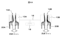
- Fig. 3 shows a model for simulating the flow of the measurement gas in the first detection chamber 13A, the second detection chamber 13B, and the resonance passage 16 shown in Fig. 2.
- this model the flow of the measurement gas when the exhaust performance of the intake and exhaust mechanisms 22A and 22B is changed is simulated, and the results are shown in Figs. 4A and 4B.
- FIG. 4A shows the case where the exhaust performance of the first intake and exhaust mechanism 22A and the second intake and exhaust mechanism 22B are the same, as shown in FIG. 1.
- the exhaust performance is shown as the air flow speed, and both are set to a flow rate of 1.0 m/s.
- no flow of the measurement gas was observed in the resonance passage 16.
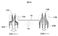
- Figure 4B shows a case where the first intake and exhaust mechanism 22A has greater exhaust performance than the second intake and exhaust mechanism 22B, as shown in Figure 2.
- the exhaust performance is shown as the air flow speed, with the flow speed set to 1.0 m/s for the first intake and exhaust mechanism 22A and 0.2 m/s for the second intake and exhaust mechanism 22B.
- a flow of the measurement gas was confirmed in the resonance passage 16.
- the intake and exhaust mechanisms 22A and 22B are driven to exhaust the measurement gas that has already been measured.
- the third embodiment also shows a configuration for discharging residual measurement gas present in the resonance passage 16.
- the same reference numbers as those in the gas detection device shown in Figure 1 indicate the same parts and components, so a repeated explanation will be omitted. However, explanations may be given as necessary.
- the first detection chamber 13A does not have a first exhaust hole 20A, and it is blocked by the substrate.
- the second detection chamber 13B has a second exhaust hole 20B. Therefore, the first intake and exhaust mechanism 1A is not provided, and only the second intake and exhaust mechanism 21B is provided in the second exhaust hole 20B. Also, the second detection chamber 13B does not have a second intake hole 14B, and it is blocked by the wall surface 12W of the housing 12.
- the first detection chamber 13A has a first intake hole 14A.
- This intake and exhaust mechanism 21B, the blocked first exhaust hole 20A of the first detection chamber 13A, and the blocked second intake hole 14B of the second detection chamber 13B function as a "pressure difference generating mechanism" that generates a flow of measurement gas in the resonance passage 16 that connects the first detection chamber 13A and the second detection chamber 13B.
- the fourth embodiment also shows a configuration for discharging residual measurement gas present in the resonance passage 16.
- the same reference numbers as those in the gas detection device shown in Figure 1 indicate the same parts and components, so a repeated explanation will be omitted. However, explanations may be given as necessary.
- the embodiment shown in FIG. 6 is a modified version of the embodiment shown in FIG. 5, and differs in that a second suction hole 14B is provided in the second detection chamber 13B. With this configuration, when replacing with a new measurement gas, the new measurement gas is also introduced from the second suction hole 14B, making it possible to efficiently discharge the measurement gas that has already been measured.
- the intake and exhaust mechanism 21B and the blocked first exhaust hole 20A of the first detection chamber 13A function as a "pressure difference generating mechanism" that generates a flow of measurement gas in the resonance passage 16 that connects the first detection chamber 13A and the second detection chamber 13B.
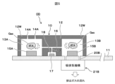
- the fifth embodiment also shows a configuration for discharging residual measurement gas present in the resonance passage 16.
- the same reference numbers as those in the gas detection device shown in Figure 1 indicate the same parts and components, so a repeated explanation will be omitted. However, explanations may be given as necessary.
- the intake and exhaust mechanism 23 is equipped with one large propeller fan.
- This propeller fan has a rotating shaft 24 and a fan 25 fixed to it.
- the center CR of the rotating shaft 24 is positioned eccentrically by ⁇ C toward the second detection chamber 13B with respect to the axis CA of the connecting passage 19.
- the amount of eccentricity ⁇ C is determined so that the second exhaust hole 20B coincides with the area where the fan 25 is most efficient at exhausting gas.
- the first exhaust hole 20A is positioned out of alignment with the area where the fan 25 is most efficient at exhausting gas due to the eccentricity of the rotating shaft 24.
- the eccentrically positioned intake and exhaust mechanism 23 functions as a "pressure difference generating mechanism" that generates a flow of measurement gas in the resonance passage 16 that connects the first detection chamber 13A and the second detection chamber 13B.
- the intake and exhaust mechanism 23 After detecting a specific gas component in the measurement gas in the first detection chamber 13A and the second detection chamber 13B with the intake and exhaust mechanism 23 stopped, if a specific gas component in the next measurement gas is to be detected, the intake and exhaust mechanism 23 is driven to exhaust the measurement gas that has already been measured.
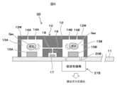
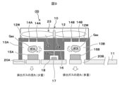
- the sixth embodiment also shows a configuration for discharging residual measurement gas present in the resonance passage 16.
- the same reference numbers as those in the gas detection device shown in Figure 1 indicate the same parts and components, so a repeated explanation will be omitted. However, explanations may be given as necessary.
- the intake and exhaust mechanism 23 is equipped with one large propeller fan.
- This propeller fan has a rotating shaft 24 and a fan 25 fixed to it.
- the center of rotation CR of the rotating shaft 24 is coaxial with the axis CA of the connecting passage 19. Therefore, the first exhaust hole 10A and the second exhaust hole 20B have the same exhaust performance.
- the discharge area of the second discharge hole 20B is larger than that of the first discharge hole 20A. Therefore, the intake and exhaust mechanism 23 discharges the measurement gas from the first discharge hole 20A and the second discharge hole 20B, but the amount of discharge is greater from the second discharge hole 20B. As a result, the pressure in the second detection chamber 13B is lower than the pressure in the first detection chamber 13A, and the measurement gas in the first detection chamber 13A flows into the second detection chamber 13B via the resonance passage 16 and is further discharged from the second discharge hole 20B.
- the intake and exhaust mechanism 23 and the second intake hole 14B formed in the second detection chamber 13B which has a larger exhaust area than the first exhaust hole 20A formed in the first detection chamber 13A, function as a "pressure difference generating mechanism" that generates a flow of measurement gas in the resonance passage 16 connecting the first detection chamber 13A and the second detection chamber 13B.
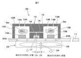
- the seventh embodiment also shows a configuration for discharging residual measurement gas present in the resonance passage 16.
- the same reference numbers as those in the gas detection device shown in Figure 1 indicate the same parts and components, so a repeated explanation will be omitted. However, explanations may be given as necessary.
- the intake and exhaust mechanism 23 is disposed on the wall surface of the housing 12 opposite the substrate 11, and is configured to supply the measurement gas to the first intake hole 14A of the first detection chamber 13A and the second intake hole 14B of the second detection chamber 13B.
- the intake and exhaust mechanism 23 is equipped with one large propeller fan, which has a rotating shaft 24 and a fan 25 fixed thereto.
- the center of rotation CR of the rotating shaft 24 is coaxial with the axis CA of the connecting passage 19. Therefore, the first suction hole 14A and the second suction hole 14B have the same discharge performance for pushing the measurement gas through them.
- the exhaust area of the second exhaust hole 20B is larger than that of the first exhaust hole 20A. Therefore, the intake and exhaust mechanism 23 exhausts gas from the first exhaust hole 20A and the second exhaust hole 20B, but the amount of gas exhausted from the second exhaust hole 20B is greater.
- the pressure in the first detection chamber 13A becomes higher than the pressure in the second detection chamber 13B, and the measurement gas in the first detection chamber 13A flows through the resonance passage 16 into the second detection chamber 13B and is then exhausted through the second exhaust hole 20B.
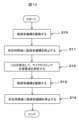
- the above-described embodiments are related to the configuration of the gas detection device, and the operation of this gas detection device (exchange of measurement gas) will now be briefly described.
- the board is equipped with a control circuit that controls the operation of the LED element, microphone, and intake and exhaust mechanism.
- the control circuit operates the LED elements 15A, 15B, and microphone 17 to perform a measurement of the measurement gas, and then operates the intake and exhaust mechanism for a predetermined period of time to exhaust the measured measurement gas from the first detection chamber 13A, the resonance passage 16, and the second detection chamber 13B.
- step S10 in FIG. 10 the intake and exhaust mechanism is first driven to exhaust the measured measurement gas remaining in the first and second detection chambers. At this time, new measurement gas is introduced into the first and second detection chambers, and new measurement gas is also introduced into the resonance passage at the same time.
- step S12 the LED element is caused to emit light at a predetermined frequency, and the intensity of the photoacoustic wave at this time is measured by a microphone. At this time, the necessary processing is carried out by the control circuit.
- step S13 the intake and exhaust mechanism is driven to exhaust the measured measurement gas and introduce new measurement gas. Furthermore, in step S14, the introduction of new measurement gas continues for a predetermined time, and the intake and exhaust mechanism is driven until the first detection chamber and the second detection chamber are filled with new measurement gas. By repeating these steps, it is possible to perform intermittent and continuous measurement of the measurement gas.
- the present invention is characterized in that the gas detection device comprises a first detection chamber and a second detection chamber with a predetermined volume, a light emitting means that emits light at a predetermined frequency and is disposed in either or both of the first detection chamber and the second detection chamber, a resonance passage that fluidly connects the first detection chamber and the second detection chamber, a measurement chamber that is fluidly connected to the resonance passage, a microphone that is disposed in the measurement chamber and measures the intensity of the acoustic wave, and an intake and exhaust mechanism that forcibly exhausts gas remaining in the first detection chamber and the second detection chamber and draws new measurement gas into the first detection chamber and the second detection chamber.
- 10 photoacoustic sensor, 11...substrate, 12...housing, 13A...first detection chamber, 13B...second detection chamber, 14A...first intake hole, 14B...second intake hole, 15A...first LED element, 15B...second LED element, 16...resonance passage, 17...microphone, 18...measurement chamber, 19...connection passage, 20A...first exhaust hole, 20B...second exhaust hole, 21A...first intake and exhaust mechanism, 21B...second intake and exhaust mechanism, 22A...first intake and exhaust mechanism, 22A...second intake and exhaust mechanism.
Landscapes
- Physics & Mathematics (AREA)
- Biochemistry (AREA)
- Health & Medical Sciences (AREA)
- Life Sciences & Earth Sciences (AREA)
- Chemical & Material Sciences (AREA)
- Analytical Chemistry (AREA)
- General Health & Medical Sciences (AREA)
- General Physics & Mathematics (AREA)
- Immunology (AREA)
- Pathology (AREA)
- Acoustics & Sound (AREA)
- Investigating Or Analyzing Materials By The Use Of Ultrasonic Waves (AREA)
- Investigating Or Analysing Materials By Optical Means (AREA)
Abstract
La présente invention concerne un appareil de détection de gaz capable d'améliorer la sensibilité de détection, de détecter simultanément une pluralité de composants gazeux, et d'éliminer l'influence d'un composant gazeux résiduel lors de la mesure continue de composants gazeux. L'appareil de détection de gaz comprend : une première chambre de détection 13A et une seconde chambre de détection 13B ayant chacune un volume prédéterminé ; des moyens d'émission de lumière 15A, 15B disposés dans la première chambre de détection et/ou la seconde chambre de détection et émettant une lumière à une fréquence prédéterminée ; un passage de résonance 16 pour relier de manière fluidique la première chambre de détection et la seconde chambre de détection ; une chambre de mesure 18 reliée de manière fluidique au passage de résonance ; un microphone 17 placé dans la chambre de mesure et mesurant l'intensité d'une onde acoustique ; et des mécanismes d'admission/échappement 21A, 21B pour évacuer de force le gaz restant dans la première chambre de détection et la seconde chambre de détection, et introduire un nouveau gaz de mesure dans la première chambre de détection et la seconde chambre de détection.
Applications Claiming Priority (2)
| Application Number | Priority Date | Filing Date | Title |
|---|---|---|---|
| JP2023095153A JP2024176562A (ja) | 2023-06-09 | 2023-06-09 | ガス検出装置 |
| JP2023-095153 | 2023-06-09 |
Publications (1)
| Publication Number | Publication Date |
|---|---|
| WO2024252727A1 true WO2024252727A1 (fr) | 2024-12-12 |
Family
ID=93795195
Family Applications (1)
| Application Number | Title | Priority Date | Filing Date |
|---|---|---|---|
| PCT/JP2024/004634 Ceased WO2024252727A1 (fr) | 2023-06-09 | 2024-02-09 | Appareil de détection de gaz |
Country Status (2)
| Country | Link |
|---|---|
| JP (1) | JP2024176562A (fr) |
| WO (1) | WO2024252727A1 (fr) |
Citations (5)
| Publication number | Priority date | Publication date | Assignee | Title |
|---|---|---|---|---|
| JPS5550142A (en) * | 1978-10-06 | 1980-04-11 | Nec Corp | Photo-acoustic gas detector |
| US5285677A (en) * | 1989-12-08 | 1994-02-15 | Oscar Oehler | Selective gas detection by field separation and velocity of sound determination, especially O2 detection |
| JP2013510293A (ja) * | 2009-11-03 | 2013-03-21 | コーニンクレッカ フィリップス エレクトロニクス エヌ ヴィ | 呼気中特定ガス濃度の測定装置 |
| CN113109268A (zh) * | 2021-05-25 | 2021-07-13 | 武汉理工大学 | 光声光谱增强装置以及使用该装置进行气体检测的方法 |
| JP2022023324A (ja) * | 2020-07-27 | 2022-02-08 | 日立グローバルライフソリューションズ株式会社 | 光音響センサ |
-
2023
- 2023-06-09 JP JP2023095153A patent/JP2024176562A/ja active Pending
-
2024
- 2024-02-09 WO PCT/JP2024/004634 patent/WO2024252727A1/fr not_active Ceased
Patent Citations (5)
| Publication number | Priority date | Publication date | Assignee | Title |
|---|---|---|---|---|
| JPS5550142A (en) * | 1978-10-06 | 1980-04-11 | Nec Corp | Photo-acoustic gas detector |
| US5285677A (en) * | 1989-12-08 | 1994-02-15 | Oscar Oehler | Selective gas detection by field separation and velocity of sound determination, especially O2 detection |
| JP2013510293A (ja) * | 2009-11-03 | 2013-03-21 | コーニンクレッカ フィリップス エレクトロニクス エヌ ヴィ | 呼気中特定ガス濃度の測定装置 |
| JP2022023324A (ja) * | 2020-07-27 | 2022-02-08 | 日立グローバルライフソリューションズ株式会社 | 光音響センサ |
| CN113109268A (zh) * | 2021-05-25 | 2021-07-13 | 武汉理工大学 | 光声光谱增强装置以及使用该装置进行气体检测的方法 |
Also Published As
| Publication number | Publication date |
|---|---|
| JP2024176562A (ja) | 2024-12-19 |
Similar Documents
| Publication | Publication Date | Title |
|---|---|---|
| US11754528B2 (en) | Gas detection device | |
| US8733162B2 (en) | Resonant flow sensor and uses and production methods for the same | |
| KR100676231B1 (ko) | 플라즈마처리장치 | |
| CN110869742A (zh) | 感测氟浓度的装置和方法 | |
| WO2024252727A1 (fr) | Appareil de détection de gaz | |
| JP2019516072A (ja) | 回転機械のための無線監視システム | |
| CN112639420A (zh) | 测定终端、测定系统、测定方法以及程序 | |
| CN104849004A (zh) | 一种电机电磁激振载荷的识别方法 | |
| CN103149135A (zh) | 细胞悬液浓度传感器 | |
| Würz et al. | Three-dimensional acoustic-roughness receptivity of a boundary layer on an airfoil: experiment and direct numerical simulations | |
| CN106969893B (zh) | 非接触式构件刚度检测设备及方法 | |
| CN1748129A (zh) | 在运行中确定涡轮机叶片应力的方法以及实施此方法的相应设备 | |
| JP2001324420A (ja) | 回転機械の翼の振動予測方法及びその装置 | |
| FI119526B (fi) | Menetelmä ja mittalaite mitata vesipitoisuutta | |
| TWI647435B (zh) | 熱致動振盪式懸浮微粒感測裝置及懸浮微粒感測方法 | |
| JP2004226264A (ja) | アンテナ及び物体検出装置 | |
| US8033169B2 (en) | Device and method for qualitative determination of the cavitation energy of ultrasound in containers | |
| JPS61114117A (ja) | 微小穴の深さ計測装置 | |
| JP2003156376A (ja) | ガスwi計測装置およびガス燃焼流量計測装置ならびにそれらに用いられるガス密度計測器 | |
| JP2022090807A (ja) | 物質検出システム | |
| KR950011838B1 (ko) | 타이어의 내부볼륨 공진주파수의 측정방법 및 장치 | |
| KR100400744B1 (ko) | 무향 시스템 | |
| RU2182065C2 (ru) | Способ запрессовки деталей и устройство для его осуществления | |
| JP3325670B2 (ja) | 塗膜厚測定装置 | |
| CN222636120U (zh) | 刻蚀腔体环境测试装置及刻蚀机台 |
Legal Events
| Date | Code | Title | Description |
|---|---|---|---|
| 121 | Ep: the epo has been informed by wipo that ep was designated in this application |
Ref document number: 24818966 Country of ref document: EP Kind code of ref document: A1 |
|
| NENP | Non-entry into the national phase |
Ref country code: DE |