WO2024252727A1 - ガス検出装置 - Google Patents
ガス検出装置 Download PDFInfo
- Publication number
- WO2024252727A1 WO2024252727A1 PCT/JP2024/004634 JP2024004634W WO2024252727A1 WO 2024252727 A1 WO2024252727 A1 WO 2024252727A1 JP 2024004634 W JP2024004634 W JP 2024004634W WO 2024252727 A1 WO2024252727 A1 WO 2024252727A1
- Authority
- WO
- WIPO (PCT)
- Prior art keywords
- detection chamber
- intake
- exhaust
- gas
- hole
- Prior art date
- Legal status (The legal status is an assumption and is not a legal conclusion. Google has not performed a legal analysis and makes no representation as to the accuracy of the status listed.)
- Ceased
Links
Images


Classifications
-
- G—PHYSICS
- G01—MEASURING; TESTING
- G01N—INVESTIGATING OR ANALYSING MATERIALS BY DETERMINING THEIR CHEMICAL OR PHYSICAL PROPERTIES
- G01N29/00—Investigating or analysing materials by the use of ultrasonic, sonic or infrasonic waves; Visualisation of the interior of objects by transmitting ultrasonic or sonic waves through the object
- G01N29/02—Analysing fluids
- G01N29/036—Analysing fluids by measuring frequency or resonance of acoustic waves
-
- G—PHYSICS
- G01—MEASURING; TESTING
- G01N—INVESTIGATING OR ANALYSING MATERIALS BY DETERMINING THEIR CHEMICAL OR PHYSICAL PROPERTIES
- G01N29/00—Investigating or analysing materials by the use of ultrasonic, sonic or infrasonic waves; Visualisation of the interior of objects by transmitting ultrasonic or sonic waves through the object
- G01N29/22—Details, e.g. general constructional or apparatus details
- G01N29/24—Probes
Definitions
- smell identification relies on the experience and senses of on-site workers, leading to increased management costs and training costs.
- the photoacoustic effect is a phenomenon in which, when light of a specific wavelength (such as laser light) is intermittently (pulsed) irradiated onto molecules of a specific component that makes up a gas, the molecules that absorb the light undergo thermal expansion and contraction, generating acoustic waves.
- Photoacoustic sensors are small and can detect gas components with high sensitivity, so they are being applied to a variety of manufacturing sites.
- the photoacoustic sensor works by using a microphone to detect acoustic waves that are generated when molecules that absorb light undergo thermal expansion and contraction.
- a microphone to detect acoustic waves that are generated when molecules that absorb light undergo thermal expansion and contraction.
- the photoacoustic sensor described in Patent Document 1 has only one detection cell, making it difficult to meet the demands for improved detection sensitivity and the ability to simultaneously detect multiple gas components.
- the object of the present invention is to provide a novel gas detection device that can solve at least one of the problems described above.
- the gas detection device comprises a first detection chamber and a second detection chamber with a predetermined volume, a light emitting means arranged in either or both of the first detection chamber and the second detection chamber for emitting light at a predetermined frequency, a resonance passage fluidly connecting the first detection chamber and the second detection chamber, a measurement chamber fluidly connected to the resonance passage, a microphone arranged in the measurement chamber for measuring the intensity of an acoustic wave, and an intake and exhaust mechanism for forcibly discharging gas remaining in the first detection chamber and the second detection chamber and drawing new measurement gas into the first detection chamber and the second detection chamber.
- the present invention makes it possible to improve detection sensitivity, detect multiple gas components simultaneously, and eliminate the effects of residual gas components when measuring gas components continuously.
- the gas detection device OD comprises at least a photoacoustic cell 10 and an intake and exhaust mechanism 21.
- the intake and exhaust mechanism 21 is made up of a first intake and exhaust mechanism 21A and a second intake and exhaust mechanism 21B.
- the first intake and exhaust mechanism 21A and the second intake and exhaust mechanism 21B are made up of propeller fans of the same specifications, but other types of fans can also be used.
- the intake and exhaust mechanism can also be a single intake and exhaust mechanism without being divided.
- the photoacoustic cell 10 is disposed on one side (hereinafter referred to as the front side) of a flat substrate (e.g., a resin substrate, etc.) 11, and the intake and exhaust mechanisms 21A, 21B are disposed on the other side (hereinafter referred to as the back side) of the substrate 11.
- the photoacoustic cell 10 is provided on the front side of the substrate 11 on which a control circuit, etc. is mounted.
- the substrate 11, the photoacoustic cell 10, and the intake and exhaust mechanism 21 are integrated as a whole into an assembly. This assembly can therefore be built into a box made of synthetic resin or the like and assembled into a gas detection device.
- the control circuit of the substrate 11 has the function of controlling the emission frequency and light intensity of the light emitting means described below, as well as the function of measuring acoustic waves from a microphone described below. For this reason, by arranging the photoacoustic cell 10 on the surface of the substrate 11 on which the control circuit is provided, connection wiring etc. is made easier.
- the photoacoustic sensor 10 includes a housing 12 made of a metal or resin material, and a first detection chamber 13A and a second detection chamber 13B with a predetermined volume are formed inside the housing 12.
- the first detection chamber 13A and the second detection chamber 13B are hollow spaces, and are formed with substantially the same shape and the same spatial volume.
- the spatial shape of the first detection chamber 13A and the second detection chamber 13B can be formed into a cylindrical shape or a rectangular parallelepiped shape. In this embodiment, the spatial shape is determined to be a cylindrical shape.
- a first suction hole 14A that fluidly connects the first detection chamber 13A to the outside is formed in the wall surface 12W of the housing 12 on the opposite side of the substrate 11 of the first detection chamber 13A.
- a second suction hole 14B that fluidly connects the second detection chamber 13B to the outside is formed in the wall surface 12W of the housing 12 on the opposite side of the substrate 11 of the second detection chamber 13B.
- suction holes 14A and 14B There may be one or more suction holes 14A and 14B, but what is important is that they have an suction area that allows the necessary amount of measurement gas to be smoothly introduced into the detection chambers 13A and 13B. In addition, the suction holes 14A and 14B have the same suction area.
- the outside refers to the space in which the gas to be measured exists, and corresponds to the manufacturing site or storage warehouse as described above. Therefore, the measurement gas present in the manufacturing site or storage warehouse is sucked into the first detection chamber 13A and the second detection chamber 13B through the first suction hole 14A and the second suction hole 14B.
- a first LED element 15A which is a first light emitting means, is disposed in the first detection chamber 13A, and the first LED element 15A emits light in a pulsed manner at a predetermined frequency to thermally excite a specific component of the measurement gas Gas in the first detection chamber 13A.
- the first LED element 15A is provided on the front side of the substrate 11, and is controlled and driven by a control circuit (not shown).
- a second LED element 15B which is a second light emitting means, is disposed in the second detection chamber 13B, and the second LED element 15B emits light in a pulsed manner at a predetermined frequency to thermally excite a specific component of the measurement gas Gas in the second detection chamber 13B.
- the second LED element 15B is also provided on the front side of the substrate 11, and is controlled and driven by a control circuit (not shown).
- the first detection chamber 13A and the second detection chamber 13B may detect the same gas component, or different gas components.
- the light emission frequency of each LED element 15A, 15B can be determined according to the gas component to be detected.
- a semiconductor laser or the like can also be used as the light emitting means.
- the first detection chamber 13A and the second detection chamber 13B are fluidly connected by a straight resonance passage 16 formed inside the housing 12.
- This resonance passage 16 has a circular cross section perpendicular to the axis of the resonance passage 16, and has the function of resonating and amplifying the minute photoacoustic waves generated in the first detection chamber 13A and the second detection chamber 13B. This makes it easy to measure the photoacoustic waves using a microphone, which will be described later.
- a measurement chamber 18 is formed on the side of the housing 12 that contacts the substrate 11, housing a microphone 17 that measures photoacoustic waves.
- the measurement chamber 18 is fluidly connected to the resonance passage 16 via a connection passage 19.
- the connection point between the resonance passage 16 and the connection passage 19 corresponds to the midpoint of the resonance passage 16 that is connected to the first detection chamber 13A and the second detection chamber 13B, ensuring the geometric symmetry of the first detection chamber 13A, the second detection chamber 13B, and the resonance passage 16.
- the first detection chamber 13A, the second detection chamber 13B, and the resonance passage 16 are shaped line-symmetrically on the page, with the axis of the connection passage 19 as the boundary.
- a microphone 17 for measuring the intensity of the photoacoustic wave is placed in the measurement chamber 18.
- the microphone 17 is provided on the front surface side of the substrate 11, and is controlled and driven by a control circuit (not shown). In this way, the photoacoustic wave generated by the light emission of the LED elements 15A and 15B is measured by the microphone 17, and the intensity of the photoacoustic wave measured by the microphone 17 is converted into an electrical signal.
- a control circuit such as that shown in Patent Document 1, for example.
- Each of the exhaust holes 20A and 20B may be one or more, but what is important is that they have an exhaust area that allows the necessary amount of measurement gas to be smoothly exhausted from the detection chambers 13A and 13B.
- the exhaust holes 20A and 204B have the same exhaust area.
- the intake and exhaust mechanisms 21A and 21B are the same type of propeller fan and have the same intake and exhaust performance.
- the intake and exhaust mechanisms 21A and 21B are driven intermittently at predetermined time intervals to forcibly exhaust the measured measurement gas in the detection chambers 13A and 13B from the exhaust holes 20A and 20B of the detection chambers 13A and 13B, and at the same time introduce new measurement gas to be used for the next measurement into the detection chambers 13A and 13B from the intake holes 14A and 14B. This means that no residual gas remains in the detection chambers 13A and 13B, making it possible to eliminate the adverse effects of residual gas.
- this embodiment includes a first detection chamber and a second detection chamber, a resonant passage that fluidly connects the first detection chamber and the second detection chamber, a microphone that detects acoustic waves, and an intake and exhaust mechanism that forcibly exhausts gas remaining in the first detection chamber and the second detection chamber and draws new measurement gas into the first detection chamber and the second detection chamber.
- the second embodiment will be described.
- the first embodiment when a specific gas component of a measurement gas is detected in the first detection chamber 13A and the second detection chamber 13B, the same measurement gas is also present in the resonance passage 16. Therefore, when the measurement of a specific gas component is completed and the measured measurement gas is discharged, there is a risk that the measurement gas present in the resonance passage 16 will remain because the performance of the first intake and exhaust mechanism 21A and the second intake and exhaust mechanism 21B are the same.
- new measurement gas is drawn in through the intake holes 14A, 14B of the first detection chamber 13A and the second detection chamber 13B, and the measured measurement gas is discharged through the exhaust holes 20A, 20B of the first detection chamber 13A and the second detection chamber 13B, and flows through the space between the first detection chamber 13A and the second detection chamber 13B, so the measurement gas in the resonance passage 16 is not discharged and becomes residual measurement gas.
- the residual measurement gas that has already been measured and is present in the resonance passage 16 may affect the new measurement gas, making it possible to make an accurate measurement impossible.
- the concentration or gas components of the residual measurement gas differ from those of the new measurement gas, it may not be possible to accurately analyze the gas components.
- the second embodiment proposes a gas detection device that can smoothly discharge the residual measurement gas that has already been measured and is present in the resonance passage 16.
- the same reference numbers as those in the gas detection device shown in Figure 1 indicate the same parts and components, so a repeated explanation will be omitted. However, explanations may be given as necessary.
- the first intake and exhaust mechanism 22A is a propeller fan with high gas exhaust performance
- the second intake and exhaust mechanism 22B is a propeller fan with low gas exhaust performance compared to the first intake and exhaust mechanism 22A.
- the first intake and exhaust mechanism 22A is a propeller fan with high static pressure (blows a lot of air)
- the second intake and exhaust mechanism 22B is a propeller fan with low static pressure (blows less air).
- the first intake and exhaust mechanism 22A and the second intake and exhaust mechanism 22B function as a "pressure difference generating mechanism" that creates a flow of measurement gas in the resonance passage 16 that connects the first detection chamber 13A and the second detection chamber 13B.
- the area of the first exhaust hole 20A is made larger than the area of the second exhaust hole 20B to allow the measurement gas to be discharged smoothly.
- the measurement gas discharged here is a mixture of the previously measured measurement gas and the new measurement gas, and the exchange of the measurement gas is completed by driving the intake and exhaust mechanisms 22A and 22B for a specified period of time.
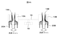
- Fig. 3 shows a model for simulating the flow of the measurement gas in the first detection chamber 13A, the second detection chamber 13B, and the resonance passage 16 shown in Fig. 2.
- this model the flow of the measurement gas when the exhaust performance of the intake and exhaust mechanisms 22A and 22B is changed is simulated, and the results are shown in Figs. 4A and 4B.
- FIG. 4A shows the case where the exhaust performance of the first intake and exhaust mechanism 22A and the second intake and exhaust mechanism 22B are the same, as shown in FIG. 1.
- the exhaust performance is shown as the air flow speed, and both are set to a flow rate of 1.0 m/s.
- no flow of the measurement gas was observed in the resonance passage 16.
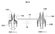
- Figure 4B shows a case where the first intake and exhaust mechanism 22A has greater exhaust performance than the second intake and exhaust mechanism 22B, as shown in Figure 2.
- the exhaust performance is shown as the air flow speed, with the flow speed set to 1.0 m/s for the first intake and exhaust mechanism 22A and 0.2 m/s for the second intake and exhaust mechanism 22B.
- a flow of the measurement gas was confirmed in the resonance passage 16.
- the intake and exhaust mechanisms 22A and 22B are driven to exhaust the measurement gas that has already been measured.
- the third embodiment also shows a configuration for discharging residual measurement gas present in the resonance passage 16.
- the same reference numbers as those in the gas detection device shown in Figure 1 indicate the same parts and components, so a repeated explanation will be omitted. However, explanations may be given as necessary.
- the first detection chamber 13A does not have a first exhaust hole 20A, and it is blocked by the substrate.
- the second detection chamber 13B has a second exhaust hole 20B. Therefore, the first intake and exhaust mechanism 1A is not provided, and only the second intake and exhaust mechanism 21B is provided in the second exhaust hole 20B. Also, the second detection chamber 13B does not have a second intake hole 14B, and it is blocked by the wall surface 12W of the housing 12.
- the first detection chamber 13A has a first intake hole 14A.
- This intake and exhaust mechanism 21B, the blocked first exhaust hole 20A of the first detection chamber 13A, and the blocked second intake hole 14B of the second detection chamber 13B function as a "pressure difference generating mechanism" that generates a flow of measurement gas in the resonance passage 16 that connects the first detection chamber 13A and the second detection chamber 13B.
- the fourth embodiment also shows a configuration for discharging residual measurement gas present in the resonance passage 16.
- the same reference numbers as those in the gas detection device shown in Figure 1 indicate the same parts and components, so a repeated explanation will be omitted. However, explanations may be given as necessary.
- the embodiment shown in FIG. 6 is a modified version of the embodiment shown in FIG. 5, and differs in that a second suction hole 14B is provided in the second detection chamber 13B. With this configuration, when replacing with a new measurement gas, the new measurement gas is also introduced from the second suction hole 14B, making it possible to efficiently discharge the measurement gas that has already been measured.
- the intake and exhaust mechanism 21B and the blocked first exhaust hole 20A of the first detection chamber 13A function as a "pressure difference generating mechanism" that generates a flow of measurement gas in the resonance passage 16 that connects the first detection chamber 13A and the second detection chamber 13B.
- the fifth embodiment also shows a configuration for discharging residual measurement gas present in the resonance passage 16.
- the same reference numbers as those in the gas detection device shown in Figure 1 indicate the same parts and components, so a repeated explanation will be omitted. However, explanations may be given as necessary.
- the intake and exhaust mechanism 23 is equipped with one large propeller fan.
- This propeller fan has a rotating shaft 24 and a fan 25 fixed to it.
- the center CR of the rotating shaft 24 is positioned eccentrically by ⁇ C toward the second detection chamber 13B with respect to the axis CA of the connecting passage 19.
- the amount of eccentricity ⁇ C is determined so that the second exhaust hole 20B coincides with the area where the fan 25 is most efficient at exhausting gas.
- the first exhaust hole 20A is positioned out of alignment with the area where the fan 25 is most efficient at exhausting gas due to the eccentricity of the rotating shaft 24.
- the eccentrically positioned intake and exhaust mechanism 23 functions as a "pressure difference generating mechanism" that generates a flow of measurement gas in the resonance passage 16 that connects the first detection chamber 13A and the second detection chamber 13B.
- the intake and exhaust mechanism 23 After detecting a specific gas component in the measurement gas in the first detection chamber 13A and the second detection chamber 13B with the intake and exhaust mechanism 23 stopped, if a specific gas component in the next measurement gas is to be detected, the intake and exhaust mechanism 23 is driven to exhaust the measurement gas that has already been measured.
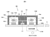
- the sixth embodiment also shows a configuration for discharging residual measurement gas present in the resonance passage 16.
- the same reference numbers as those in the gas detection device shown in Figure 1 indicate the same parts and components, so a repeated explanation will be omitted. However, explanations may be given as necessary.
- the intake and exhaust mechanism 23 is equipped with one large propeller fan.
- This propeller fan has a rotating shaft 24 and a fan 25 fixed to it.
- the center of rotation CR of the rotating shaft 24 is coaxial with the axis CA of the connecting passage 19. Therefore, the first exhaust hole 10A and the second exhaust hole 20B have the same exhaust performance.
- the discharge area of the second discharge hole 20B is larger than that of the first discharge hole 20A. Therefore, the intake and exhaust mechanism 23 discharges the measurement gas from the first discharge hole 20A and the second discharge hole 20B, but the amount of discharge is greater from the second discharge hole 20B. As a result, the pressure in the second detection chamber 13B is lower than the pressure in the first detection chamber 13A, and the measurement gas in the first detection chamber 13A flows into the second detection chamber 13B via the resonance passage 16 and is further discharged from the second discharge hole 20B.
- the intake and exhaust mechanism 23 and the second intake hole 14B formed in the second detection chamber 13B which has a larger exhaust area than the first exhaust hole 20A formed in the first detection chamber 13A, function as a "pressure difference generating mechanism" that generates a flow of measurement gas in the resonance passage 16 connecting the first detection chamber 13A and the second detection chamber 13B.
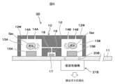
- the seventh embodiment also shows a configuration for discharging residual measurement gas present in the resonance passage 16.
- the same reference numbers as those in the gas detection device shown in Figure 1 indicate the same parts and components, so a repeated explanation will be omitted. However, explanations may be given as necessary.
- the intake and exhaust mechanism 23 is disposed on the wall surface of the housing 12 opposite the substrate 11, and is configured to supply the measurement gas to the first intake hole 14A of the first detection chamber 13A and the second intake hole 14B of the second detection chamber 13B.
- the intake and exhaust mechanism 23 is equipped with one large propeller fan, which has a rotating shaft 24 and a fan 25 fixed thereto.
- the center of rotation CR of the rotating shaft 24 is coaxial with the axis CA of the connecting passage 19. Therefore, the first suction hole 14A and the second suction hole 14B have the same discharge performance for pushing the measurement gas through them.
- the exhaust area of the second exhaust hole 20B is larger than that of the first exhaust hole 20A. Therefore, the intake and exhaust mechanism 23 exhausts gas from the first exhaust hole 20A and the second exhaust hole 20B, but the amount of gas exhausted from the second exhaust hole 20B is greater.
- the pressure in the first detection chamber 13A becomes higher than the pressure in the second detection chamber 13B, and the measurement gas in the first detection chamber 13A flows through the resonance passage 16 into the second detection chamber 13B and is then exhausted through the second exhaust hole 20B.
- the above-described embodiments are related to the configuration of the gas detection device, and the operation of this gas detection device (exchange of measurement gas) will now be briefly described.
- the board is equipped with a control circuit that controls the operation of the LED element, microphone, and intake and exhaust mechanism.
- the control circuit operates the LED elements 15A, 15B, and microphone 17 to perform a measurement of the measurement gas, and then operates the intake and exhaust mechanism for a predetermined period of time to exhaust the measured measurement gas from the first detection chamber 13A, the resonance passage 16, and the second detection chamber 13B.
- step S10 in FIG. 10 the intake and exhaust mechanism is first driven to exhaust the measured measurement gas remaining in the first and second detection chambers. At this time, new measurement gas is introduced into the first and second detection chambers, and new measurement gas is also introduced into the resonance passage at the same time.
- step S12 the LED element is caused to emit light at a predetermined frequency, and the intensity of the photoacoustic wave at this time is measured by a microphone. At this time, the necessary processing is carried out by the control circuit.
- step S13 the intake and exhaust mechanism is driven to exhaust the measured measurement gas and introduce new measurement gas. Furthermore, in step S14, the introduction of new measurement gas continues for a predetermined time, and the intake and exhaust mechanism is driven until the first detection chamber and the second detection chamber are filled with new measurement gas. By repeating these steps, it is possible to perform intermittent and continuous measurement of the measurement gas.
- the present invention is characterized in that the gas detection device comprises a first detection chamber and a second detection chamber with a predetermined volume, a light emitting means that emits light at a predetermined frequency and is disposed in either or both of the first detection chamber and the second detection chamber, a resonance passage that fluidly connects the first detection chamber and the second detection chamber, a measurement chamber that is fluidly connected to the resonance passage, a microphone that is disposed in the measurement chamber and measures the intensity of the acoustic wave, and an intake and exhaust mechanism that forcibly exhausts gas remaining in the first detection chamber and the second detection chamber and draws new measurement gas into the first detection chamber and the second detection chamber.
- 10 photoacoustic sensor, 11...substrate, 12...housing, 13A...first detection chamber, 13B...second detection chamber, 14A...first intake hole, 14B...second intake hole, 15A...first LED element, 15B...second LED element, 16...resonance passage, 17...microphone, 18...measurement chamber, 19...connection passage, 20A...first exhaust hole, 20B...second exhaust hole, 21A...first intake and exhaust mechanism, 21B...second intake and exhaust mechanism, 22A...first intake and exhaust mechanism, 22A...second intake and exhaust mechanism.
Landscapes
- Physics & Mathematics (AREA)
- Biochemistry (AREA)
- Health & Medical Sciences (AREA)
- Life Sciences & Earth Sciences (AREA)
- Chemical & Material Sciences (AREA)
- Analytical Chemistry (AREA)
- General Health & Medical Sciences (AREA)
- General Physics & Mathematics (AREA)
- Immunology (AREA)
- Pathology (AREA)
- Acoustics & Sound (AREA)
- Investigating Or Analyzing Materials By The Use Of Ultrasonic Waves (AREA)
- Investigating Or Analysing Materials By Optical Means (AREA)
Abstract
検出感度を向上したり、複数のガス成分を同時に検出したりすることができ、また、継続してガス成分を測定する場合に、残留ガス成分の影響を排除することができるガス検出装置を提供する。 所定の容積を備えた第1の検出室13A及び第2の検出室13Bと、第1の検出室と第2の検出室のどちらか一方、或いは両方に配置された、所定の周波数で発光する発光手段15A,15Bと、第1の検出室と第2の検出室を流体的に接続する共鳴通路16と、共鳴通路に流体的に接続された測定室18と、測定室に配置され音響波の強度を測定するマイクロフォン17と、第1の検出室と第2の検出室に残留するガスを強制的に排出して新たな測定ガスを第1の検出室と第2の検出室に吸入する吸排気機構21A、21Bとを備えている。
Description
本発明は匂い等の原因となる気体(ガス)の成分を検出するガス検出装置 に係り、特に光音響センサを用いて気体成分を検出するガス検出装置に関するものである。
味噌や醤油等の醸造品、化粧品等の製造現場や食品を保管する保管倉庫においては、匂い(香りとも言う)の品質管理項目があるが、DX(デジタルトランスフォーメーション)化が困難である。このため、匂いの識別は現場作業員の経験や感覚に頼っており、管理コストの増加や教育コストの増加を招いている。
そして、最近では匂いセンサによって匂いの定量化(ガスの種類、濃度等)を図ることで、DX化による品質管理の効率を向上する試みがなされている。匂いの定量化には目的に応じたガス成分や匂い成分を検知するガスセンサが必要である。ガス成分や匂い成分を検出するセンサとして、例えば、特開2020-78418号公報(特許文献1)に記載されたような、光音響効果を用いた光音響センサが提案されている。
光音響効果は、ガスを構成する特定成分の分子に対して、特定の波長の光(レーザ光等)を断続的(パルス状)に照射すると、光を吸収した分子が熱膨張、及び収縮を行うことで音響波が発生する現象である。光音響センサは、小型でガス成分を高感度に検出が可能なため、種々の製造現場での適用が進められている。
ところで、光音響センサは、光を吸収した分子が熱膨張、及び収縮を行うことで発生する音響波をマイクロフォンで検出する原理である。そして、検出感度を向上したり、複数のガス成分を同時に検出したりすることが求められる。しかしながら、特許文献1に記載された光音響センサでは、検出セルが1個であるため、検出感度を向上したり、複数のガス成分を同時に検出したりする要請に応えることは困難であった。また、継続してガス成分を計測する場合は、検出セル内の残留ガスを強制的に排出して、残留ガス成分の影響を排除することも必要である。
本発明の目的は、上述した課題の少なくとも1つ以上の課題を解決することができる新規なガス検出装置 を提供することにある。
本発明は、ガス検出装置 が、所定の容積を備えた第1の検出室及び第2の検出室と、第1の検出室と第2の検出室のどちらか一方、或いは両方に配置された、所定の周波数で発光する発光手段と、第1の検出室と第2の検出室を流体的に接続する共鳴通路と、共鳴通路に流体的に接続された測定室と、測定室に配置され音響波の強度を測定するマイクロフォンと、第1の検出室と第2の検出室に残留するガスを強制的に排出して新たな測定ガスを第1の検出室と第2の検出室に吸入する吸排気機構とを備えている、ことを特徴としている。
本発明によれば、検出感度を向上したり、複数のガス成分を同時に検出したりすることができ、また、継続してガス成分を測定する場合に、残留ガス成分の影響を排除することができる。
以下、本発明の実施形態について図面を用いて詳細に説明するが、本発明は以下の実施形態に限定されることなく、本発明の技術的な概念の中で種々の変形例や応用例をもその範囲に含むものである。
図1において、ガス検出装置 ODは、少なくとも光音響セル10と吸排気機構21を備えている。尚、本実施形態形態では、吸排気機構21は第1の吸排気機構21Aと、第2の吸排気機構21Bからなっている。また、第1の吸排気機構21Aと第2の吸排気機構21Bは同じ仕様のプロペラファンから構成されているが、これ以外の形式のファンを用いることもできる。また、吸排気機構を分割せずに1個の吸排気機構とすることもできる。
光音響セル10は、平板状の基板(例えば、樹脂基板等)11の一方の面(以下、表面と表記する)に配置され、吸排気機構21A、21Bは、基板11の他方の面(以下、裏面と表記する)に配置されている。特に光音響セル10は、制御回路等が実装された基板11の表面上に設けられている。このように、基板11、光音響セル10、及び吸排気機構21とは、全体的に見て一体化されて組立体とされている。したがって、この組立体を合成樹脂等の箱体に組み込んで、ガス検出装置 として組み立てることができる。
基板11の制御回路は、後述する発光手段の発光周波数や光の強度を制御する機能や、また後述するマイクロフォンから音響波を測定する機能を備えている。このため、光音響セル10を制御回路が設けられた基板11の表面に配置することで、接続配線等を容易にしている。
光音響センサ10は、金属材料や樹脂材料からなる筐体12を備えており、筐体12の内部には所定の容積を備えた第1の検出室13A、及び第2の検出室13Bが形成されている。第1の検出室13A、及び第2の検出室13Bは、空洞の空間であり、実質的に同じ形状で同じ空間容積に形成されている。例えば、第1の検出室13A、及び第2の検出室13Bの空間形状は、円柱形状や直方体形状に形成することができる。本実施形態では、空間形状は円柱形状に決められている。
第1の検出室13Aの基板11とは反対側の筐体12の壁面12Wには、第1の検出室13Aと外部を流体的に接続する第1の吸入透孔14Aが形成されている。同様に、第2の検出室13Bの基板11とは反対側の筐体12の壁面12Wには、第2の検出室13Bと外部を流体的に接続する第2の吸入透孔14Bが形成されている。
吸入透孔14A、14Bは、1個であっても良いし、複数個であっても良いものであり、要は必要な量の測定ガスが円滑に検出室13A、13Bに導入できる吸入面積を備えていれば良いものである。また、吸入透孔14A、14Bは、同じ吸入面積とされている。
ここで、外部とは測定すべきガス(気体)が存在する空間であり、上述したような製造現場や保管倉庫が該当する。したがって、製造現場や保管倉庫に存在する測定ガスが、第1の吸入透孔14A、第2の吸入透孔14Bから第1の検出室13A、及び第2の検出室13Bに吸入されるものである。
第1の検出室13A内には、第1の発光手段である第1のLED素子15Aが配置されており、第1のLED素子15Aを所定の周波数でパルス的に発光させて、第1の検出室13A内の測定ガスGasの特定成分を熱的に励起させている。第1のLED素子15Aは、基板11の表面の側に設けられて、図示しない制御回路によって制御、駆動される。
同様に、第2の検出室13B内には、第2の発光手段である第2のLED素子15Bが配置されており、第2のLED素子15Bを所定の周波数でパルス的に発光させて、第2の検出室13B内の測定ガスGasの特定成分を熱的に励起させている。第2のLED素子15Bも、基板11の表面の側に設けられて、図示しない制御回路によって制御、駆動される。
ここで、第1の検出室13A、及び第2の検出室13Bは、同じガス成分を検出しても良いし、異なったガス成分を検出しても良い。この場合は、検出すべきガス成分に合せて、それぞれのLED素子15A、15Bの発光周波数を決めてやれば良い。このように、2個の検出室13A、13Bを設けて、同じガス成分を検出したり、異なったガス成分を検出したりすることができる。尚、LED素子に代えて、発光手段として半導体レーザ等を用いることもできる。更には、どちらか一方の検出室にだけに発光手段(LEDやレーザ)を設け、他方の検出室を共鳴室として使用することもできる。
第1の検出室13Aと第2の検出室13Bは、筐体の12の内部に形成された直管状の共鳴通路16によって流体的に接続されている。この共鳴通路16は、共鳴通路16の軸線に直交する断面が円形状に形成されており、第1の検出室13Aと第2の検出室13Bで生じる微小な光音響波を、共鳴増幅させる機能を備えている。これによって、後述するマイクロフォンによって光音響波の測定を容易にしている。
また、筐体12の基板11に接する側には、光音響波を測定するマイクロフォン17を収納する測定室18が形成されている。測定室18は、共鳴通路16と接続通路19を介して流体的に接続されている。共鳴通路16と接続通路19の接続点は、第1の検出室13Aと第2の検出室13Bに接続される共鳴通路16の中点に相当し、第1の検出室13Aと第2の検出室13B及び共鳴通路16の形状的な対称性を確保している。つまり、接続通路19の軸線を境にして、第1の検出室13Aと第2の検出室13B及び共鳴通路16は、紙面上で線対称の形状とされてる。
測定室18内には、光音響波の強度を測定するためのマイクロフォン17が配置されている。マイクロフォン17は、基板11の表面の側に設けられ、図示しない制御回路によって、制御、駆動される。このように、LED素子15A、15Bの発光によって生じた光音響波は、マイクロフォン17で測定され、また、マイクロフォン17で測定された光音響波の強度は、電気信号に変換される。これらの処理は、例えば特許文献1に示すような制御回路によって処理される。
また、第1の検出室13Aが位置する基板11には、第1の検出室13Aと第1の吸排気機構21Aとを流体的に接続する第1の排出透孔20Aが形成されている。同様に、第2の検出室13Bが位置する基板11には、第2の検出室13Bと第2の吸排気機構21Bとを流体的に接続する第2の排出透孔20Bが形成されている。そして、吸入透孔14A、14Bと排出透孔20A、20Bは、互いに向き合う位置に形成されており、測定ガスが流れやすい位置関係とされている。
排出透孔20A、20Bの夫々は、1個であっても良いし、複数個であっても良いものであり、要は必要な量の測定ガスが円滑に検出室13A、13Bから排出できる排出面積を備えていれば良いものである。また、排出透孔20A、204Bは、同じ排出面積とされている。
吸排気機構21A、21Bは、同じ型式のプロペラファンであり、同じ吸排気性能を備えている。そして、吸排気機構21A、21Bは、所定時間毎に間欠的に駆動されており、検出室13A、13Bの測定済みの測定ガスを、検出室13A、13Bの排気透孔20A、20Bから強制的に排出し、同時に吸気透孔14A、14Bから次の測定に使用する新たな測定ガスを検出室13A、13Bに導入している。これによって、検出室13A、13Bにおいては、残留ガスが存在しなくなるので、残留ガスによる悪影響をなくすことが可能となる。
このように、本実施形態によれば、第1の検出室及び第2の検出室と、第1の検出室と第2の検出室を流体的に接続する共鳴通路と、音響波を検出するマイクロフォンと、第1の検出室と第2の検出室に残留するガスを強制的に排出して新たな測定ガスを第1の検出室と第2の検出室に吸入する吸排気機構とを備えている。
したがって、検出感度を向上したり、複数のガス成分を同時に検出したりすることができ、また、継続してガス成分を測定する場合に、それぞれの検出室の残留ガス成分の影響を排除することができる。
次に第2の実施形態について説明する。第1の実施形態においては、第1の検出室13Aと第2の検出室13Bで測定ガスの特定ガス成分を検出する場合、共鳴通路16にも同じ測定ガスが存在している。このため、特定ガス成分の測定が完了して測定済みの測定ガスを排出する場合、第1の吸排気機構21Aと第2の吸排気機構21Bの性能が同じであるため、共鳴通路16に存在する測定ガスが残留する恐れがる。
つまり、第1の検出室13Aと第2の検出室13Bの吸入透孔14A、14Bから吸入される新たな測定ガスと、第1の検出室13Aと第2の検出室13Bの排出透孔20A、20Bから排出される測定済みの測定ガスは、第1の検出室13Aと第2の検出室13Bの空間を通過して流れるため、共鳴通路16の測定ガスが排出されないで残留測定ガスになる。
このため、新たな測定ガスを測定する場合、共鳴通路16に存在する測定済みの残留測定ガスが、新たな測定ガスに対して影響を与え、正確な測定ができなくなる恐れがある。つまり、残留測定ガスの濃度やガス成分が、新たな測定ガスと異なっている場合、正確なガス成分の分析ができなくなる恐れがある。
そこで、第2の実施形態では、共鳴通路16に存在する測定済みの残留測定ガスを円滑に排出することができるガス検出装置 を提案するものである。ここで、図1に示すガス検出装置 と同じ参照番号は、同じ部品、構成要素を表すので改めて説明するのは省略する。ただ、必要に応じて説明する場合もある。
図2において、第1の吸排気機構22Aはガス排出性能が大きいプロペラファンであり、第2の吸排気機構22Bは、第1の吸排気機構22Aにガス排出性能が小さいプロペラファンである。つまり、第1の吸排気機構22Aは、静圧が大きい(風を多く送る)プロペラファンであり、第2の吸排気機構22Bは、静圧が小さい(風を少なく送る)プロペラファンである。
このため、第1の検出室13A内の圧力は、第2の検出室13B内の圧力より低くなり、この圧力差で共鳴通路16に新たな測定ガスの流れを生じるようになる。この第1の吸排気機構22A、及び第2の吸排気機構22Bが、第1の検出室13Aと第2の検出室13Bを接続する共鳴通路16に測定ガスの流れを生成する「圧力差発生機構」として機能する。
また、第1の吸排気機構22Aの働きによって、第2の検出室13Bから共鳴通路16を介して、測定ガスが第1の検出室13Aに余分に流れてくるので、これに合せて第1の排出透孔20Aの面積を、第2の排出透孔20Bの面積より大きくして、円滑に測定ガスが排出されるようにしている。
ここで、排出される測定ガスは、測定済みの測定ガスと新たな測定ガスの混合されたガスであり、吸排気機構22A、22Bを所定時間だけ駆動することで、測定ガスの交換が完了する。
図3は、図2に示す第1の検出室13A、第2の検出室13B、共鳴通路16の測定ガスの流れを模擬するためのモデルを示している。このモデルを使用して、吸排気機構22A、22Bの排出性能を変化させたときの測定ガスの流れをシミュレートし、その結果を図4A、図4Bに示している。
図4Aでは、図1に示すように、第1の吸排気機構22Aと第2の吸排気機構22Bの排気性能を同じにした場合を示している。ここでは、排気性能を送風速度で示しており、共に流速1.0m/sとして設定した。図4Aからわかるように、共鳴通路16には測定ガスの流れは確認できなかった。
一方、図4Bでは、図2に示すように、第1の吸排気機構22Aの方が第2の吸排気機構22Bより排気性能を大きくした場合を示している。ここでは、排気性能を送風速度で示しており、第1の吸排気機構22Aでは流速1.0m/sとし、第2の吸排気機構22Bでは流速0.2m/sとして設定した。図4Bからわかるように、共鳴通路16に測定ガスの流れが確認できた。
そして、本実施形態では、吸排気機構22A、22Bを停止した状態で、第1の検出室13A、第2の検出室13Bの測定ガスの特定ガス成分を検出した後に、新たに次の測定ガスの特定ガス成分を検出する場合は、吸排気機構22A、22Bを駆動して、測定済みの測定ガスを排出する。
この時、第1の吸排気機構22Aの排出性能が大きいので、第1の検出室13Aと第2の検出室13Bの間に圧力差が発生し、第2の検出室13Bから共鳴通路16を介して、新たな測定ガスが第1の検出室13に流れて排出されるので、共鳴通路16の残留測定ガスが存在しなくなる。この状態で、吸排気機構22A、22Bを停止して、第1の検出室13A、第2の検出室13Bの新たな測定ガスのガス成分を検出する。
このように、本実施形態では、新たな測定ガスを測定する場合、共鳴通路に存在する測定済みの残留測定ガスが存在しなくなるので、新たな測定ガスに対して悪影響を与えず、正確な測定ガスの検出を行うことができる。
次に第3の実施形態について説明する。第3の実施形態においても、共鳴通路16に存在する残留測定ガスを排出する構成を示している。ここで、図1に示すガス検出装置 と同じ参照番号は、同じ部品、構成要素を表すので改めて説明するのは省略する。ただ、必要に応じて説明する場合もある。
図5において、第1の検出室13Aには第1の排出透孔20Aが形成されておらず、基板よって閉塞されている。一方、第2の検出室13Bには第2の排出透孔20Bが形成されている。このため、第1の吸排気機構1Aは設けられておらず、第2の吸排気機構21Bのみが第2の排出透孔20Bに設けられている。また、第2の検出室13Bには第2の吸入透孔14Bが形成されておらず、筐体12の壁面12Wによって閉塞されている。一方、第1の検出室13Aには第1の吸入透孔14Aが形成されている。
この吸排気機構21Bと、第1の検出室13Aの閉塞された第1の排出透孔20Aと、第2の検出室13Bの閉塞された第2の吸入透孔14Bとが、第1の検出室13Aと第2の検出室13Bを接続する共鳴通路16に測定ガスの流れを生成する「圧力差発生機構」として機能する。
したがって、測定ガスの交換を行うために第2の吸排気機構21Bを駆動すると、新たな測定ガスは、第1の吸入透孔14Aから流入し、第1の検出室13Aの測定済みの測定ガスと共に共鳴通路16に流れ、更に第2の検出室13Bの測定済みの測定ガスと共に排出透孔19Bから排出される。このように、新たな測定ガスを、第1の吸入透孔14A→第1の検出室13A→共鳴通路16→第2の検出室13B→排出透孔19Bの順で流すので、第1の検出室13A、第2の検出室13B、共鳴通路16の残留測定ガスを排出することができるようになる。
このように、本実施形態においても、新たな測定ガスを測定する場合、共鳴通路に存在する測定済みの残留測定ガスが存在しなくなるので、新たな測定ガスに対して悪影響を与えず、正確な測定ガスの検出を行うことができる。また、吸排気機構の数を少なくできるので、全体の製造コストを低減できると共に、使用中の消費電力を削減することができる。
次に第4の実施形態について説明する。第4の実施形態においても、共鳴通路16に存在する残留測定ガスを排出する構成を示している。ここで、図1に示すガス検出装置 と同じ参照番号は、同じ部品、構成要素を表すので改めて説明するのは省略する。ただ、必要に応じて説明する場合もある。
図6に示す実施形態おいては、図5に示す実施形態の変形例であり、異なっている構成は、第2の検出室13Bに第2の吸入透孔14Bが設けられている点である。この構成によれば、新たな測定ガスに交換する場合、第2の吸入透孔14Bからも新たな測定ガスが導入されるので、測定済みの測定ガスの効率的な排出が可能となる。
この実施形態においても、吸排気機構21Bと、第1の検出室13Aの閉塞された第1の排出透孔20Aが、第1の検出室13Aと第2の検出室13Bを接続する共鳴通路16に測定ガスの流れを生成する「圧力差発生機構」として機能する。
このように、本実施形態においても、新たな測定ガスを測定する場合、共鳴通路に存在する測定済みの残留測定ガスが存在しなくなるので、新たな測定ガスに対して悪影響を与えず、正確な測定ガスの検出を行うことができる。また、吸排気機構の数を少なくできるので、全体の製造コストを低減できると共に、使用中の消費電力を削減することができる。
次に第5の実施形態について説明する。第5の実施形態においても、共鳴通路16に存在する残留測定ガスを排出する構成を示している。ここで、図1に示すガス検出装置 と同じ参照番号は、同じ部品、構成要素を表すので改めて説明するのは省略する。ただ、必要に応じて説明する場合もある。
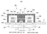
図7において、吸排気機構23は、1個の大型のプロペラファンを備えている。このプロペラファンは、回転軸24と、これに固定されたファン25を備えている。ここで、回転軸24の中心CRは、接続通路19の軸心CAに対して、ΔCだけ第2の検出室13Bの側に偏心された位置に配置されている。
ここで、ΔCの偏心量は、第2の排出透孔20Bと、ファン25が最もガスを排出する効率が大きい領域とが一致する位置に決められている。一方、これに対して、第1の排出透孔20Aは、回転軸24の偏心によって、第1の排出透孔20Aは、ファン25が最もガスを排出する効率が大きい領域とずれる位置となる。
この実施形態においては、偏心して配置された吸排気機構23が、第1の検出室13Aと第2の検出室13Bを接続する共鳴通路16に測定ガスの流れを生成する「圧力差発生機構」として機能する。
そして、本実施形態では、吸排気機構23を停止した状態で、第1の検出室13A、第2の検出室13Bの測定ガスの特定ガス成分を検出した後に、新たに次の測定ガスの特定ガス成分を検出する場合は、吸排気機構23を駆動して、測定済みの測定ガスを排出する。
この時、第2の排気透孔20Bの方が、排出性能が大きいので、第1の検出室13Aと第2の検出室13Bの間に圧力差が発生し、第1の検出室13Aから共鳴通路16を介して、新たな測定ガスが第2の検出室13Bに流れて排出されるので、共鳴通路16の残留測定ガスが存在しなくなる。この状態で、吸排気機構23を停止して、第1の検出室13A、第2の検出室13Bの新たな測定ガスのガス成分を検出する。
このように、本実施形態でも、新たな測定ガスを測定する場合、共鳴通路に存在する測定済みの残留測定ガスが存在しなくなるので、新たな測定ガスに対して悪影響を与えず、正確な測定ガスの検出を行うことができる。また、吸排気機構の数を少なくできるので、全体の製造コストを低減できると共に、使用中の消費電力を削減することができる。
次に第6の実施形態について説明する。第6の実施形態においても、共鳴通路16に存在する残留測定ガスを排出する構成を示している。ここで、図1に示すガス検出装置 と同じ参照番号は、同じ部品、構成要素を表すので改めて説明するのは省略する。ただ、必要に応じて説明する場合もある。
図8において、吸排気機構23は、1個の大型のプロペラファンを備えている。このプロペラファンは、回転軸24と、これに固定されたファン25を備えている。ここで、回転軸24の回転中心CRは、接続通路19の軸心CAに対して同軸心とされている。したがって、第1の排出透孔10Aと第2の排出透孔20Bに対して同じ排出性能である。
一方、第2の排出透孔20Bの排出面積は、第1の排出透孔20Aに比べて大きい排出面積を有している。このため、吸排気機構23によって、第1の排出透孔20Aと第2の排出透孔20Bから測定ガスが排出されるが、第2の排出透孔20Bの方が排出量として多くなる。このため、第2の検出室13Bの圧力の方が、第1の検出室13Aの圧力より低くなり、第1の検出室13Aの測定ガスは共鳴通路16を介して第2の検出室13Bに流れ、更に第2の排出透孔20Bから排出される。
この実施形態においても、吸排気機構23と、第1の検出室13Aに形成された第1の排出透孔20Aより排出面積が大きい第2の検出室13Bに形成された第2の吸入透孔14Bとが、第1の検出室13Aと第2の検出室13Bを接続する共鳴通路16に測定ガスの流れを生成する「圧力差発生機構」として機能する。
このように、本実施形態でも、新たな測定ガスを測定する場合、共鳴通路に存在する測定済みの残留測定ガスが存在しなくなるので、新たな測定ガスに対して悪影響を与えず、正確な測定ガスの検出を行うことができる。また、吸排気機構の数を少なくできるので、全体の製造コストを低減できると共に、使用中の消費電力を削減することができる。
次に第7の実施形態について説明する。第7の実施形態においても、共鳴通路16に存在する残留測定ガスを排出する構成を示している。ここで、図1に示すガス検出装置 と同じ参照番号は、同じ部品、構成要素を表すので改めて説明するのは省略する。ただ、必要に応じて説明する場合もある。
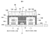
図9において、吸排気機構23は、筐体12の基板11の反対側の壁面に配置され、第1の検出室13Aの第1の吸入透孔14Aと、第2の検出室13Bの第2の吸入透孔14Bに測定ガスを供給するように構成されている。吸排気機構23は、1個の大型のプロペラファンを備えており、このプロペラファンは、回転軸24と、これに固定されたファン25を備えている。
ここで、回転軸24の回転中心CRは、接続通路19の軸心CAに対して同軸心とされている。したがって、第1の吸入透孔14Aと第2の吸入透孔14Bに対して、測定ガスを押し込む排出性能は同じである。
一方、第2の排出透孔20Bの排出面積は、第1の排出透孔20Aに比べて大きい排出面積を有している。このため、吸排気機構23によって、第1の排出透孔20Aと第2の排出透孔20Bからガスが排出されるが、第2の排出透孔20Bの方が排出量として多くなる。
このため、第1の検出室13Aの圧力の方が、第2の検出室13Bの圧力より高くなり、第1の検出室13Aの測定ガスは共鳴通路16を介して第2の検出室13Bに流れ、更に第2の排出透孔20Bから排出される。
この実施形態においても、吸排気機構23と、第1の検出室13Aに形成された第1の排出透孔20Aより排出面積が大きい第2の検出室13Bに形成された第2の吸入透孔14Bとが、第1の検出室13Aと第2の検出室13Bを接続する共鳴通路16に測定ガスの流れを生成する「圧力差発生機構」として機能する。
このように、本実施形態でも、新たな測定ガスを測定する場合、共鳴通路に存在する測定済みの残留測定ガスが存在しなくなるので、新たな測定ガスに対して悪影響を与えず、正確な測定ガスの検出を行うことができる。また、吸排気機構の数を少なくできるので、全体の製造コストを低減できると共に、使用中の消費電力を削減することができる。
以上に説明した夫々の実施形態は、ガス検出装置の構成についてであるが、次にこのガス検出装置の動作(測定ガスの交換)について簡単に説明する。基板には、LED素子、マイクロフォン、及び吸排気機構の動作を制御する制御回路が搭載されており、制御回路は、LED素子15A、15B、及びマイクロフォン17を動作させて測定スの測定を実行した後に、吸排気機構を所定時間だけ動作させて、第1の検出室13A、共鳴通路16、及び第2の検出室13Bの測定済みの測定ガスを排出するものである。
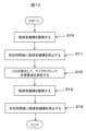
図10のステップS10においては、先ず吸排気機構を駆動して第1の検出室と第2の検出室に残留している測定済みの測定ガスを排出する。この時、新たな測定ガスが、第1の検出室と第2の検出室に導入されると共に、共鳴通路も同時に新たな測定ガスが導入される。
次に、ステップS11で所定時間に亘って新たな測定ガスの導入を継続し、第1の検出室と第2の検出室が、新たな測定ガスで満たされるまで吸排気機構を駆動する。
次に、ステップS12でLED素子を所定の周波数で発光させ、この時の光音響波の強度をマイクロフォンで測定する。この時、制御回路によって必要な処理が実行される。
次に、測定済みの測定ガスを排気し、また新たな測定ガスを導入するため、ステップS13で吸排気機構を駆動する。更に、ステップS14で所定時間に亘って新たな測定ガスの導入を継続し、第1の検出室と第2の検出室が、新たな測定ガスで満たされるまで吸排気機構を駆動する。これらの繰り返しよって、間欠的に連続して測定ガスの測定を実施することができる。
このような測定動作を行うことで、共鳴通路の残留ガスを排出し、更に測定時の吸排気機構の動作を停止するので、吸排気機構(例えば、プロペラファン)の動作音をマイクロフォンが採取することが抑制されるので、高精度な匂いの時系列変化の測定が可能になる。
以上の通り、本発明は、ガス検出装置が、所定の容積を備えた第1の検出室及び第2の検出室と、第1の検出室と第2の検出室のどちらか一方、或いは両方に配置された、所定の周波数で発光する発光手段と、第1の検出室と第2の検出室を流体的に接続する共鳴通路と、共鳴通路に流体的に接続された測定室と、測定室に配置され音響波の強度を測定するマイクロフォンと、第1の検出室と第2の検出室に残留するガスを強制的に排出して新たな測定ガスを第1の検出室と第2の検出室に吸入する吸排気機構とを備えている、ことを特徴としている。
これによれば、検出感度を向上したり、複数のガス成分を同時に検出したりすることができ、また、継続してガス成分を測定する場合に、残留ガス成分の影響を排除することができる。
尚、本発明は上記したいくつかの実施例に限定されるものではなく、様々な変形例が含まれる。上記の実施例は本発明を分かりやすく説明するために詳細に説明したものであり、必ずしも説明した全ての構成を備えるものに限定されるものではない。また、ある実施例の構成の一部を他の実施例の構成に置き換えることが可能であり、ある実施例の構成に他の実施例の構成を加えることも可能である。各実施例の構成について、他の構成の追加、削除、置換をすることも可能である。
10…光音響センサ、11…基板、12…筐体、13A…第1の検出室、13B…第2の検出室、14A…第1の吸入透孔、14B…第2の吸入透孔、15A…第1のLED素子、15B…第2のLED素子、16…共鳴通路、17…マイクロフォン、18…測定室、19…接続通路、20A…第1の排出透孔、20B…第2の排出透孔、21A…第1の吸排気機構、21B…第2の吸排気機構、22A…第1の吸排気機構、22A…第2の吸排気機構。
Claims (14)
- 所定の容積を備えた、第1の検出室及び第2の検出室と、
前記第1の検出室と前記第2の検出室のどちらか一方、或いは両方に配置された、所定の周波数で発光する発光手段と、
前記第1の検出室と前記第2の検出室を流体的に接続する共鳴通路と、
前記共鳴通路に流体的に接続された測定室と、
前記測定室に配置され、光音響波の強度を測定するマイクロフォンと、
前記第1の検出室と前記第2の検出室に残留する測定済みの測定ガスを強制的に排出して新たな測定ガスを前記第1の検出室と前記第2の検出室に吸入する吸排気機構と
を備えていることを特徴とするガス検出装置。 - 請求項1に記載のガス検出装置において、
前記第1の検出室と前記第2の検出室、前記発光手段、前記共鳴通路、前記測定室、及びマイクロフォンは、基板の一方の面に配置され、
前記吸排気機構は、前記基板の他方の面に配置されている
ことを特徴とするガス検出装置。 - 請求項2に記載のガス検出装置において、
前記吸排気機構は、前記第1の検出室と前記第2の検出室に対応して個別に設けられているか、或いは前記第1の検出室と前記第2の検出室に共通して設けれている
ことを特徴とするガス検出装置。 - 請求項3に記載のガス検出装置において、
前記第1の検出室には、前記新たな測定ガスが導入される第1の吸入透孔と、前記測定済みの測定ガスを前記吸排気機構に流す第1の排出透孔が設けられ、
前記第2の検出室には、前記新たな測定ガスが導入される第2の吸入透孔と、前記測定済みの測定ガスを前記吸排気機構に流す第2の排出透孔が設けられている
ことを特徴とするガス検出装置。 - 所定の容積を備えた、第1の検出室及び第2の検出室と、
前記第1の検出室と前記第2の検出室のどちらか一方、或いは両方に配置された、所定の周波数で発光する発光手段と、
前記第1の検出室と前記第2の検出室を流体的に接続する共鳴通路と、
前記共鳴通路に流体的に接続された測定室と、
前記測定室に配置され、光音響波の強度を測定するマイクロフォンと、
前記第1の検出室と前記第2の検出室に残留する測定済みの測定ガスを強制的に排出して新たな測定ガスを前記第1の検出室と前記第2の検出室に吸入する吸排気機構と
前記吸排気機構が動作されている時に、前記第1の検出室と前記第2の検出室に圧力差を発生して前記共鳴通路に残留する前記測定済みの測定ガスを排出する圧力差発生機構とを備えていることを特徴とするガス検出装置。 - 請求項5に記載のガス検出装置において、
前記第1の検出室と前記第2の検出室、前記発光手段、前記共鳴通路、前記測定室、及びマイクロフォンは、基板の一方の面に配置され、
前記吸排気機構は、前記基板の他方の面に配置されている
ことを特徴とするガス検出装置。 - 請求項6に記載のガス検出装置において、
前記第1の検出室には、前記新たな測定ガスが導入される第1の吸入透孔と、前記測定済みの測定ガスを前記吸排気機構に流す第1の排出透孔が設けられ、
前記第2の検出室には、前記新たな測定ガスが導入される第2の吸入透孔と、前記測定済みの測定ガスを前記吸排気機構に流す第2の排出透孔が設けられ、
前記吸排気機構は、前記第1の排出透孔に接続された第1の吸排気機構と、前記第2の排出透孔に接続された第2の吸排気機構とからなり、
前記圧力差発生機構は、前記第1の吸排気機構と前記第2の吸排気機構の一方が他方より前記測定済みの測定ガスの排出量が多く決められていることで、前記第1の検出室と前記第2の検出室に圧力差を発生する
ことを特徴とするガス検出装置。 - 請求項6に記載のガス検出装置において、
前記第1の検出室には、前記新たな測定ガスが導入される吸入透孔と、
前記第2の検出室には、前記測定済みの測定ガスを前記吸排気機構に流す排出透孔が設けられ、
前記圧力差発生機構は、前記吸排気機構が前記排出透孔に接続されることで、前記第1の検出室と前記第2の検出室に圧力差を発生して、前記新たな測定ガスを、前記吸入透孔、前記第1の検出室、前記共鳴通路、前記第2の検出室、及び前記排出透孔の順で流す
ことを特徴とするガス検出装置。 - 請求項8に記載のガス検出装置において、
前記第2の検出室には、前記新たな測定ガスが導入される第2の吸入透孔が設けられている
ことを特徴とするガス検出装置。 - 請求項6に記載のガス検出装置において、
前記第1の検出室には、前記新たな測定ガスが導入される第1の吸入透孔と、前記測定済みの測定ガスを前記吸排気機構に流す第1の排出透孔が設けられ、
前記第2の検出室には、前記新たな測定ガスが導入される第2の吸入透孔と、前記測定済みの測定ガスを前記吸排気機構に流す第2の排出透孔が設けられ、
前記吸排気機構は、前記第1の排出透孔と前記第2の排出透孔に接続された1個のプロペラファンであり、
前記圧力差発生機構は、前記プロペラファンの回転軸の軸心を前記第1の排出透孔、或いは前記第2の排出透孔の側に偏心させて配置することで、前記第1の検出室と前記第2の検出室に圧力差を発生する
ことを特徴とするガス検出装置。 - 請求項6に記載のガス検出装置において、
前記第1の検出室には、前記新たな測定ガスが導入される第1の吸入透孔と、前記測定済みの測定ガスを前記吸排気機構に流す第1の排出透孔が設けられ、
前記第2の検出室には、前記新たな測定ガスが導入される第2の吸入透孔と、前記測定済みの測定ガスを前記吸排気機構に流す第2の排出透孔が設けられ、
前記吸排気機構は、前記第1の排出透孔と前記第2の排出透孔に接続された1個の吸排気機構であり、
前記圧力差発生機構は、前記第1の排出透孔、或いは前記第2の排出透孔の一方の排出面積を他方の排出面積より大きくすることで、前記第1の検出室と前記第2の検出室に圧力差を発生する
ことを特徴とするガス検出装置。 - 請求項6に記載のガス検出装置において、
前記第1の検出室には、前記新たな測定ガスが導入される第1の吸入透孔と、前記測定済みの測定ガスを前記吸排気機構に流す第1の排出透孔が設けられ、
前記第2の検出室には、前記新たな測定ガスが導入される第2の吸入透孔と、前記測定済みの測定ガスを前記吸排気機構に流す第2の排出透孔が設けられ、
前記吸排気機構は、前記第1の吸入透孔と前記第2の吸入透孔に接続された1個の吸排気機構であり、
前記圧力差発生機構は、前記第1の排出透孔、或いは前記第2の排出透孔の一方の排出面積を他方の排出面積より大きくすることで、前記第1の検出室と前記第2の検出室に圧力差を発生する
ことを特徴とするガス検出装置。 - 請求項5に記載のガス検出装置において、
前記第1の検出室と前記第2の検出室、前記発光手段、前記共鳴通路、前記測定室、及びマイクロフォンは、基板の一方の面に配置され、前記吸排気機構は、前記基板の他方の面に配置される共に、
前記基板には、前記発光手段、前記マイクロフォン、及び前記吸排気機構の動作を制御する制御手段が搭載されており、
前記制御手段は、前記発光手段、及びマイクロフォンを動作させて前記新たな測定ガスの測定を実行した後に、前記吸排気機構を所定時間だけ動作させて、前記第1の検出室、前記共鳴通路、及び前記第2の検出室の前記測定済みの測定ガスを排出する
ことを特徴とするガス検出装置。 - 所定の容積を備えた、第1の検出室及び第2の検出室と、
前記第1の検出室と前記第2の検出室のどちらか一方、或いは両方に配置された、所定の周波数で発光する発光手段と、
前記第1の検出室と前記第2の検出室を流体的に接続する共鳴通路と、
前記共鳴通路に流体的に接続された測定室と、
前記測定室に配置され、光音響波の強度を測定するマイクロフォンと、を備え、
前記第1の検出室、または前記第2の検出室の少なくとも一方には、前記発光手段が設けられている面に、測定ガスが通過する通過孔が設けられている
ことを特徴とするガス検出装置。
Applications Claiming Priority (2)
| Application Number | Priority Date | Filing Date | Title |
|---|---|---|---|
| JP2023095153A JP2024176562A (ja) | 2023-06-09 | 2023-06-09 | ガス検出装置 |
| JP2023-095153 | 2023-06-09 |
Publications (1)
| Publication Number | Publication Date |
|---|---|
| WO2024252727A1 true WO2024252727A1 (ja) | 2024-12-12 |
Family
ID=93795195
Family Applications (1)
| Application Number | Title | Priority Date | Filing Date |
|---|---|---|---|
| PCT/JP2024/004634 Ceased WO2024252727A1 (ja) | 2023-06-09 | 2024-02-09 | ガス検出装置 |
Country Status (2)
| Country | Link |
|---|---|
| JP (1) | JP2024176562A (ja) |
| WO (1) | WO2024252727A1 (ja) |
Citations (5)
| Publication number | Priority date | Publication date | Assignee | Title |
|---|---|---|---|---|
| JPS5550142A (en) * | 1978-10-06 | 1980-04-11 | Nec Corp | Photo-acoustic gas detector |
| US5285677A (en) * | 1989-12-08 | 1994-02-15 | Oscar Oehler | Selective gas detection by field separation and velocity of sound determination, especially O2 detection |
| JP2013510293A (ja) * | 2009-11-03 | 2013-03-21 | コーニンクレッカ フィリップス エレクトロニクス エヌ ヴィ | 呼気中特定ガス濃度の測定装置 |
| CN113109268A (zh) * | 2021-05-25 | 2021-07-13 | 武汉理工大学 | 光声光谱增强装置以及使用该装置进行气体检测的方法 |
| JP2022023324A (ja) * | 2020-07-27 | 2022-02-08 | 日立グローバルライフソリューションズ株式会社 | 光音響センサ |
-
2023
- 2023-06-09 JP JP2023095153A patent/JP2024176562A/ja active Pending
-
2024
- 2024-02-09 WO PCT/JP2024/004634 patent/WO2024252727A1/ja not_active Ceased
Patent Citations (5)
| Publication number | Priority date | Publication date | Assignee | Title |
|---|---|---|---|---|
| JPS5550142A (en) * | 1978-10-06 | 1980-04-11 | Nec Corp | Photo-acoustic gas detector |
| US5285677A (en) * | 1989-12-08 | 1994-02-15 | Oscar Oehler | Selective gas detection by field separation and velocity of sound determination, especially O2 detection |
| JP2013510293A (ja) * | 2009-11-03 | 2013-03-21 | コーニンクレッカ フィリップス エレクトロニクス エヌ ヴィ | 呼気中特定ガス濃度の測定装置 |
| JP2022023324A (ja) * | 2020-07-27 | 2022-02-08 | 日立グローバルライフソリューションズ株式会社 | 光音響センサ |
| CN113109268A (zh) * | 2021-05-25 | 2021-07-13 | 武汉理工大学 | 光声光谱增强装置以及使用该装置进行气体检测的方法 |
Also Published As
| Publication number | Publication date |
|---|---|
| JP2024176562A (ja) | 2024-12-19 |
Similar Documents
| Publication | Publication Date | Title |
|---|---|---|
| US11754528B2 (en) | Gas detection device | |
| US8733162B2 (en) | Resonant flow sensor and uses and production methods for the same | |
| KR100676231B1 (ko) | 플라즈마처리장치 | |
| CN110869742A (zh) | 感测氟浓度的装置和方法 | |
| WO2024252727A1 (ja) | ガス検出装置 | |
| JP2019516072A (ja) | 回転機械のための無線監視システム | |
| CN112639420A (zh) | 测定终端、测定系统、测定方法以及程序 | |
| CN104849004A (zh) | 一种电机电磁激振载荷的识别方法 | |
| CN103149135A (zh) | 细胞悬液浓度传感器 | |
| Würz et al. | Three-dimensional acoustic-roughness receptivity of a boundary layer on an airfoil: experiment and direct numerical simulations | |
| CN106969893B (zh) | 非接触式构件刚度检测设备及方法 | |
| CN1748129A (zh) | 在运行中确定涡轮机叶片应力的方法以及实施此方法的相应设备 | |
| JP2001324420A (ja) | 回転機械の翼の振動予測方法及びその装置 | |
| FI119526B (fi) | Menetelmä ja mittalaite mitata vesipitoisuutta | |
| TWI647435B (zh) | 熱致動振盪式懸浮微粒感測裝置及懸浮微粒感測方法 | |
| JP2004226264A (ja) | アンテナ及び物体検出装置 | |
| US8033169B2 (en) | Device and method for qualitative determination of the cavitation energy of ultrasound in containers | |
| JPS61114117A (ja) | 微小穴の深さ計測装置 | |
| JP2003156376A (ja) | ガスwi計測装置およびガス燃焼流量計測装置ならびにそれらに用いられるガス密度計測器 | |
| JP2022090807A (ja) | 物質検出システム | |
| KR950011838B1 (ko) | 타이어의 내부볼륨 공진주파수의 측정방법 및 장치 | |
| KR100400744B1 (ko) | 무향 시스템 | |
| RU2182065C2 (ru) | Способ запрессовки деталей и устройство для его осуществления | |
| JP3325670B2 (ja) | 塗膜厚測定装置 | |
| CN222636120U (zh) | 刻蚀腔体环境测试装置及刻蚀机台 |
Legal Events
| Date | Code | Title | Description |
|---|---|---|---|
| 121 | Ep: the epo has been informed by wipo that ep was designated in this application |
Ref document number: 24818966 Country of ref document: EP Kind code of ref document: A1 |
|
| NENP | Non-entry into the national phase |
Ref country code: DE |