WO2024252735A1 - Steel cord, cord-rubber composite, and tire - Google Patents
Steel cord, cord-rubber composite, and tire Download PDFInfo
- Publication number
- WO2024252735A1 WO2024252735A1 PCT/JP2024/005840 JP2024005840W WO2024252735A1 WO 2024252735 A1 WO2024252735 A1 WO 2024252735A1 JP 2024005840 W JP2024005840 W JP 2024005840W WO 2024252735 A1 WO2024252735 A1 WO 2024252735A1
- Authority
- WO
- WIPO (PCT)
- Prior art keywords
- cord
- rubber
- steel cord
- point
- wire
- Prior art date
- Legal status (The legal status is an assumption and is not a legal conclusion. Google has not performed a legal analysis and makes no representation as to the accuracy of the status listed.)
- Ceased
Links
Images


Classifications
-
- B—PERFORMING OPERATIONS; TRANSPORTING
- B60—VEHICLES IN GENERAL
- B60C—VEHICLE TYRES; TYRE INFLATION; TYRE CHANGING; CONNECTING VALVES TO INFLATABLE ELASTIC BODIES IN GENERAL; DEVICES OR ARRANGEMENTS RELATED TO TYRES
- B60C9/00—Reinforcements or ply arrangement of pneumatic tyres
-
- B—PERFORMING OPERATIONS; TRANSPORTING
- B60—VEHICLES IN GENERAL
- B60C—VEHICLE TYRES; TYRE INFLATION; TYRE CHANGING; CONNECTING VALVES TO INFLATABLE ELASTIC BODIES IN GENERAL; DEVICES OR ARRANGEMENTS RELATED TO TYRES
- B60C9/00—Reinforcements or ply arrangement of pneumatic tyres
- B60C9/18—Structure or arrangement of belts or breakers, crown-reinforcing or cushioning layers
- B60C9/20—Structure or arrangement of belts or breakers, crown-reinforcing or cushioning layers built-up from rubberised plies each having all cords arranged substantially parallel
-
- D—TEXTILES; PAPER
- D07—ROPES; CABLES OTHER THAN ELECTRIC
- D07B—ROPES OR CABLES IN GENERAL
- D07B1/00—Constructional features of ropes or cables
- D07B1/06—Ropes or cables built-up from metal wires, e.g. of section wires around a hemp core
Definitions
- This disclosure relates to steel cords, cord-rubber composites, and tires.
- Patent Document 1 discloses a steel cord for reinforcing tires, which is formed by twisting together 2 to 13 steel wires having a wire diameter of 0.23 to 0.50 mm, and which is characterized in that the cord has an elongation rate of 1.5 to 3.0% when subjected to a tensile load of 10% of the breaking load, and the value A shown in the following formula is 50 to 100 N/%.
- the steel cord of the present disclosure is a steel cord having a 1 ⁇ 4 structure in which four wires are twisted together,
- the wire has a diameter of 0.15 mm or more and 0.20 mm or less,
- When embedded in rubber, in a cross section perpendicular to the longitudinal direction of the steel cord When a region surrounded by a common tangent line between adjacent wires that is in contact with the outer surface of the steel cord and a line segment that connects centers of adjacent wires along the outer surface of the steel cord is defined as a composite region, and an area of the composite region is defined as an effective cross-sectional area,
- the effective cross-sectional area is equal to or greater than 0.099 mm 2 and equal to or less than 0.224 mm 2 .
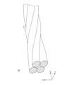
- FIG. 1 is a perspective view of a steel cord according to one embodiment of the present disclosure.
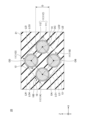
- FIG. 2 is a cross-sectional view of a plane perpendicular to the longitudinal direction of a steel cord according to one embodiment of the present disclosure, in a state in which the steel cord is embedded in rubber to form a cord-rubber composite.
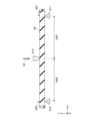
- FIG. 3 is an explanatory diagram of a corrugated wire.
- FIG. 4 is a cross-sectional view of a cord-rubber composite according to one embodiment of the present disclosure.
- FIG. 5 is a cross-sectional view of a tire according to one aspect of the disclosure.
- FIG. 6 is an explanatory diagram of a method for evaluating bending rigidity.
- FIG. 7 is an explanatory diagram of a method for evaluating durability.
- the thickness of the rubber in the cord-rubber composite is selected so that the steel cord can be embedded. For this reason, one possible way to make the cord-rubber composite lighter is to reduce the wire diameter of the wires that make up the steel cord, thereby reducing the outer diameter of the steel cord (cord diameter) and thus the thickness of the cord-rubber composite. However, if the wire diameter is reduced, the cord-rubber composite may be more susceptible to breakage when repeatedly bent, which could reduce its durability.
- the present disclosure aims to provide a stranded steel cord that, when applied to a cord-rubber composite, can reduce the weight of the cord-rubber composite while increasing its durability.
- This disclosure provides a stranded steel cord that, when applied to a cord-rubber composite, can reduce the weight of the cord-rubber composite while increasing its durability.
- a steel cord according to one embodiment of the present disclosure is a steel cord having a 1 ⁇ 4 structure in which four wires are twisted together,
- the wire has a diameter of 0.15 mm or more and 0.20 mm or less,
- When embedded in rubber, in a cross section perpendicular to the longitudinal direction of the steel cord When a region surrounded by a common tangent line between adjacent wires that is in contact with the outer surface of the steel cord and a line segment that connects centers of adjacent wires along the outer surface of the steel cord is defined as a composite region, and an area of the composite region is defined as an effective cross-sectional area,
- the effective cross-sectional area is equal to or greater than 0.099 mm 2 and equal to or less than 0.224 mm 2 .
- the outer diameter of the steel cord can be reduced.
- the thickness of the cord-rubber composite is selected so that the steel cord contained therein can be embedded. Therefore, by reducing the outer diameter of the steel cord according to one embodiment of the present disclosure, the thickness of the cord-rubber composite can also be reduced, and the cord-rubber composite and tires including the cord-rubber composite can be made lighter.
- the number of steel cords required to achieve the desired bending rigidity can be reduced for a cord-rubber composite including a steel cord according to one embodiment of the present disclosure. This allows for weight reduction of the cord-rubber composite and tires including the cord-rubber composite.
- the bending rigidity of the cord-rubber composite body can be set within an appropriate range, and durability can be improved.
- the ratio of the area of the region in which steel is distributed to the effective cross-sectional area in the cross section may be 30% or more and 128% or less.
- the area ratio of the steel region which is the ratio of the area of the region where steel is distributed to the effective cross-sectional area
- the bending rigidity of the cord-rubber composite can be increased when the cord-rubber composite is made.
- the area ratio of the steel region is set to 128% or less, the bending rigidity of the cord-rubber composite can be prevented from becoming excessively high when the cord-rubber composite is made. As a result, the durability of the cord-rubber composite can be particularly increased.
- At least one of the wires is a first corrugated wire having a first bent portion and a first non-bent portion repeatedly along a longitudinal direction,
- the three first bent portions successive along the length of the first corrugated wire are defined as a first point, a second point, and a third point,
- the first corrugated wire may have a ratio of the wire diameter to the first corrugation height of 1.029 or more and 1.818 or less.
- the ratio of wire diameter D to first corrugation height H1 By setting D/H1, the ratio of wire diameter D to first corrugation height H1, to 1.818 or less, the distance between adjacent wires in the steel cord is increased and the rubber penetration rate is increased when the steel cord is embedded in rubber to form a cord-rubber composite. As a result, when a cord-rubber composite is formed, the adhesion between the steel cord and rubber is improved, and the bending rigidity of the cord-rubber composite is increased.
- D/H1 1.029 By making D/H1 1.029 or more, it is possible to prevent the rubber penetration rate from becoming excessively high when the steel cord is embedded in rubber to form a cord-rubber composite. As a result, when a cord-rubber composite is formed, the adhesion between the steel cord and the rubber can be set in a particularly preferable range, and the bending rigidity of the cord-rubber composite can be prevented from becoming excessively high. As a result, the durability of the cord-rubber composite can be particularly improved.
- a ratio of the first corrugation pitch of the first corrugated wire to a twist pitch of the steel cord may be 0.09 or more and 0.35 or less.
- the ratio of the first corrugated pitch of the first corrugated wire to the twist pitch of the steel cord is 0.35 or less, the distance between adjacent wires in the steel cord is increased, and the rubber penetration rate is increased when the steel cord is embedded in rubber to form a cord-rubber composite.
- the adhesion between the steel cord and rubber is improved, and the bending rigidity of the cord-rubber composite is particularly increased.
- the ratio of the first corrugation pitch of the first corrugated wire to the twist pitch of the steel cord is 0.09 or more, it is possible to prevent the rubber penetration degree from becoming excessively high when the steel cord is embedded in rubber to form a cord-rubber composite.
- the adhesion between the steel cord and the rubber can be set to a particularly preferable range, and the bending rigidity of the cord-rubber composite can be prevented from becoming excessively high.
- the durability of the cord-rubber composite can be particularly improved.
- At least one of the four wires, excluding the first corrugated wire, is a second corrugated wire having second bent portions and second non-bent portions repeatedly along a longitudinal direction,
- the three second bent portions successive along the length of the second corrugated wire are a fourth point, a fifth point, and a sixth point
- the shortest distance between the fifth point and a straight line passing through an end of the second corrugated wire that is closest to the fifth point among the fourth point and the sixth point is defined as a second corrugation height
- the distance between the fourth point and the sixth point of the second corrugated wire is defined as a second corrugation pitch
- the second corrugated wire has a ratio of the wire diameter to the second corrugation height of 1.029 or more and 1.818 or less
- a ratio of the second corrugation pitch of the second corrugated wire to a twist pitch of the steel cord may be 0.50 or more and 1.50 or less.
- the ratio of wire diameter D to second corrugation height H2, to 1.818 or less By setting D/H2, the ratio of wire diameter D to second corrugation height H2, to 1.818 or less, the distance between adjacent wires in the steel cord is increased, and the rubber penetration rate is increased when the steel cord is embedded in rubber to form a cord-rubber composite. As a result, when a cord-rubber composite is formed, the adhesion between the steel cord and rubber is improved, and the bending rigidity of the cord-rubber composite is increased.
- D/H2 1.029 By making D/H2 1.029 or more, it is possible to prevent the rubber penetration rate from becoming excessively high when the steel cord is embedded in rubber to form a cord-rubber composite.
- the adhesion between the steel cord and the rubber can be set in a particularly preferable range, and the bending rigidity of the cord-rubber composite can be prevented from becoming excessively high.
- the durability of the cord-rubber composite can be particularly improved.
- the ratio of the second corrugation pitch of the second corrugated wire to the twist pitch of the steel cord (P2/Psc) to 1.50 or less, the distance between adjacent wires in the steel cord can be increased, and the rubber penetration rate can be increased when the steel cord is embedded in rubber to form a cord-rubber composite. This allows the effective cross-sectional area to be increased.
- the initial elongation may be 0.20% or more and 0.50% or less.
- the initial elongation 0.20% or more it is possible to improve the impact resistance, which is the ability to prevent the steel cord from breaking when a force perpendicular to the longitudinal direction of the steel cord is applied.
- the rubber penetration rate of the steel cord may be 60% or more.
- the adhesion between the steel cord and the rubber can be improved when a cord-rubber composite is made, and the bending rigidity of the cord-rubber composite can be increased.
- a cord-rubber composite according to one embodiment of the present disclosure comprises a rubber, and a steel cord according to any one of (1) to (7) embedded in the rubber.
- the cord-rubber composite according to one aspect of the present disclosure can reduce the thickness and weight of the cord-rubber composite or a tire using the cord-rubber composite. Furthermore, the cord-rubber composite according to one aspect of the present disclosure can increase the durability of the cord-rubber composite or a tire using the cord-rubber composite.
- a tire according to one embodiment of the present disclosure includes a steel cord according to any one of (1) to (7).
- the thickness of the belt layer can be reduced, making the tire including the belt layer lighter, and reducing the rolling resistance of the tire.
- a tire according to one aspect of the present disclosure can be made to have excellent durability.
- Fig. 1 is a perspective view of a steel cord 10 of this embodiment.
- Fig. 2 is a cross-sectional view of a plane perpendicular to the longitudinal direction of the steel cord 10 in a state in which the steel cord 10 of this embodiment is embedded in rubber 21 to form a cord-rubber composite 20.
- the Y axis in Figs. 1 and 2 is an axis along the longitudinal direction of the steel cord 10.
- the XZ plane in Figs. 1 and 2 is a plane perpendicular to the longitudinal direction of the steel cord 10.
- the steel cord 10 of this embodiment is a stranded steel cord formed by stranding together four wires 11, that is, wires 11A, 11B, 11C, and 11D (see FIG. 2 ).
- the four wires 11 are twisted together in a spiral shape along the longitudinal direction of the steel cord 10, as shown in FIG.
- the steel cord 10 of the present embodiment may have a 1 ⁇ 4 structure, which is a single-twist structure.
- a single-twist structure such as a 1 ⁇ N structure, means a structure in which N element wires 11 are twisted together to form a single layer (one layer).
- the single layer means a structure in which the element wires 11 are arranged in a row along the circumference of a circle in a cross section perpendicular to the longitudinal direction of the steel cord 10.
- the wire diameter D (see FIG. 2) of the wire 11 of the steel cord 10 of the present embodiment can be set to 0.15 mm or more and 0.20 mm or less.
- the outer diameter of the steel cord 10 can be reduced.
- the thickness of the cord-rubber composite is selected so that the steel cord 10 contained therein can be embedded. Therefore, by reducing the outer diameter of the steel cord 10 in this embodiment, the thickness of the cord-rubber composite using the steel cord 10 can also be reduced, making it possible to reduce the weight of the cord-rubber composite and tires including the cord-rubber composite.
- the wire 11 of the steel cord 10 of this embodiment may be composed of only a wire rod 111, or may have a brass plating film 112 on its surface (see FIG. 2). Specifically, the wire 11 may have the wire rod 111 and the brass plating film 112 covering the wire rod 111.
- the wire 111 may be, for example, a steel wire, and a high carbon steel wire may also be used.
- the brass plating film 112 may include copper (Cu) and zinc (Zn). As shown in FIG. 2, the brass plating film 112 may be disposed so as to cover the side surface of the wire 111.
- the adhesive layer thus produced can improve the initial adhesive performance between the steel cord 10 and the rubber 21.
- Initial adhesive performance refers to the adhesive performance between the steel cord 10 and the rubber 21 immediately after vulcanization during the manufacture of the cord-rubber composite or a tire that includes the cord-rubber composite.
- the zinc contained in the brass plating film 112 is thought to promote and control the reaction that forms the adhesive layer.
- the brass plating film 112 may contain elements other than copper and zinc.
- the brass plating film 112 may further contain one or more elements selected from cobalt (Co), nickel (Ni), tin (Sn), iron (Fe), and manganese (Mn).
- the additive elements cobalt, nickel, tin, iron, and manganese have a greater tendency to ionize than copper. Therefore, when the brass plating film 112 contains an additive element in addition to copper and zinc, the brass plating film 112 functions as a sacrificial anticorrosion agent or can make the composite potential of copper and zinc more noble. Therefore, when the brass plating film 112 contains an additive element, the corrosion resistance of the steel cord 10 can be improved.
- (2-3) Corrugated Wire Some or all of the wires 11 contained in the steel cord 10 of this embodiment may be corrugated wires 30 having bent portions 31 and non-bent portions 32 repeatedly along the length as shown in Fig. 3. By making some or all of the wires 11 corrugated, the penetration degree of rubber into the steel cord 10, the elongation characteristics of the steel cord 10, etc. can be adjusted and selected.
- the shape and size of the corrugation can be selected according to the characteristics to be adjusted by the corrugated wire, and are not particularly limited.
- first corrugated wire For example, in the steel cord 10 of the present embodiment, at least one of the wires 11 may be a first corrugated wire having first bent portions and first non-bent portions alternately along the longitudinal direction.
- FIG. 3 shows the first corrugated wire 300 placed on a plane S such that the plane S is perpendicular to a plane passing through the first bent portion 31, which is the bent portion, and the first non-bent portion 32, which is the non-bent portion.
- the first bends which are three consecutive bends 31 along the length of the first corrugated wire 300, are referred to as the first point, second point, and third point.
- the first point is bend 31A
- the second point is bend 31B
- the third point is bend 31C.
- the shortest distance between the second point and a straight line LA passing through the end 30A of the first corrugated wire 300 that is closest to the second point among the first and third points is defined as the first corrugation height H1.
- the first corrugation height H1 can also be defined as the distance between the straight line LA and a straight line LB that is parallel to the straight line LA that passes through the end 30B of the first corrugated wire 300 that is closest to the first and third points among the second points.
- the shortest distance between the first bends, which are the bends 31, along the vertical direction of the plane S can also be defined as the first corrugation height H1. That is, for example, the shortest length along the vertical direction of the plane S between the bend 31A, which is the first point, or the bend 31C, which is the third point, and the bend 31B, which is the second point, can also be defined as the first corrugation height H1. Therefore, in FIG. 3, the first corrugation height H1 is the distance along the vertical direction of the plane S between the opposing parts of the first corrugated wire 300 at the bends 31A and 31B, for example.
- the first corrugated wire 300 can have a ratio D/H1, which is the ratio of the wire diameter D (see Figure 2) to the first corrugation height H1, of 1.029 or more and 1.818 or less.
- the distance between adjacent wires 11 in the steel cord 10 can be increased, and the degree of rubber penetration can be increased when the steel cord 10 is embedded in rubber to form a cord-rubber composite.
- the adhesion between the steel cord 10 and the rubber can be improved, and the bending rigidity of the cord-rubber composite can be increased.
- D/H1 1.029 By making D/H1 1.029 or more, it is possible to prevent the rubber penetration rate from becoming excessively high when the steel cord 10 is embedded in rubber to form a cord-rubber composite. Therefore, when a cord-rubber composite is formed, the adhesion between the steel cord 10 and the rubber can be set in a particularly preferable range, and the bending rigidity of the cord-rubber composite can be prevented from becoming excessively high. As a result, the durability of the cord-rubber composite can be particularly improved.
- the distance between the first bend 31A, which is the first point, and the third bend 31C, which is the third point, of the first corrugated wire 300 is defined as the first corrugated pitch P1.
- the distance between the first bends, which are adjacent bends 31 along the plane S when the first corrugated wire 300 is placed on the plane S can also be defined as the first corrugated pitch P1.
- the distance between the first bends, which is the distance along the plane S, between the first bend 31A, which is the first point, and the third bend 31C, which is the distance between the first bends can be defined as the first corrugated pitch P1.
- P1/Psc which is the ratio of the first corrugation pitch P1 of the first corrugated wire 300 to the twist pitch Psc of the steel cord, may be 0.09 or more and 0.35 or less, 0.10 or more and 0.34 or less, 0.11 or more and 0.33 or less, or 0.15 or more and 0.33 or less.
- the distance between adjacent wires 11 in the steel cord 10 can be increased, and the rubber penetration can be increased when the steel cord 10 is embedded in rubber to form a cord-rubber composite.
- P1/Psc the distance between adjacent wires 11 in the steel cord 10
- the rubber penetration can be increased when the steel cord 10 is embedded in rubber to form a cord-rubber composite.
- the adhesion between the steel cord 10 and the rubber can be improved, and the bending rigidity of the cord-rubber composite can be increased.
- the steel cord 10 of the present embodiment may have, as the corrugated wires 30, in addition to the first corrugated wires 300, a second corrugated wire 310 having different corrugation conditions.
- the number of each corrugated wire is not particularly limited, and the number of the first corrugated wires 300 and the number of the second corrugated wires 310 may be the same.
- the steel cord 10 of this embodiment may contain more first corrugated wires 300 than the number of the second corrugated wires 310.
- the steel cord 10 of this embodiment may contain more second corrugated wires 310 than the number of the first corrugated wires 300.
- At least one of the four wires 11, excluding the first corrugated wire 300, can be a second corrugated wire 310 having second bent portions and second non-bent portions repeatedly along the length.
- the second corrugated wire 310 can be configured in the same way as the first corrugated wire 300, except for the different corrugation conditions, so an example configuration will be explained using Figure 3.
- FIG. 3 shows the second corrugated wire 310 placed on plane S such that plane S is perpendicular to a plane passing through the second bent portion, which is bent portion 31, and the second non-bent portion, which is non-bent portion 32.
- the second bends which are three consecutive bends 31 along the length of the second corrugated wire 310, are designated as the fourth point, fifth point, and sixth point.
- the fourth point is bend 31A
- the fifth point is bend 31B
- the sixth point is bend 31C.
- the shortest distance between the fifth point and the straight line LA passing through the end of the second corrugated wire 310 closest to the fifth point among the fourth and sixth points is defined as the second corrugation height H2.
- the second corrugation height H2 can also be defined as the distance between the straight line LA and the straight line LB parallel to the straight line LA passing through the end 30B of the second corrugated wire 310 closest to the fourth and sixth points among the fifth points.
- the second corrugation height H2 is the distance along the vertical direction of the plane S between the opposing portions of the second corrugated wire 310 at the bends 31A and 31B, for example.
- the second corrugated wire 310 can have a ratio D/H2, which is the ratio of the wire diameter D (see Figure 2) to the second corrugation height H2, of 1.029 or more and 1.818 or less.
- the distance between adjacent wires 11 in the steel cord 10 can be increased, and the degree of rubber penetration can be increased when the steel cord 10 is embedded in rubber to form a cord-rubber composite.
- the adhesion between the steel cord 10 and the rubber can be improved, and the bending rigidity of the cord-rubber composite can be increased.
- D/H2 1.029 By making D/H2 1.029 or more, it is possible to prevent the rubber penetration rate from becoming excessively high when the steel cord 10 is embedded in rubber to form a cord-rubber composite. Therefore, when a cord-rubber composite is formed, the adhesion between the steel cord 10 and the rubber can be set in a particularly preferable range, and the bending rigidity of the cord-rubber composite can be prevented from becoming excessively high. As a result, the durability of the cord-rubber composite can be particularly improved.
- the distance between the bend 31A, which is the fourth point of the second corrugated wire 310, and the bend 31C, which is the sixth point, is defined as the second corrugation pitch P2.
- the distance between the second bends, which are adjacent bends 31 along the plane S of the second corrugated wire 310, can also be defined as the second corrugation pitch P2.
- the distance between the bend 31A, which is the fourth point, and the bend 31C, which is the sixth point, which is the distance between the second bends along the plane S can be defined as the second corrugation pitch P2.
- P2/Psc which is the ratio of the second corrugation pitch P2 of the second corrugated wire 310 to the twist pitch Psc of the steel cord, may be, for example, 0.50 or more and 1.50 or less, 0.52 or more and 1.48 or less, or 0.53 or more and 1.47 or less.
- the distance between adjacent wires 11 in the steel cord 10 can be increased, and the rubber penetration rate can be increased when the steel cord is embedded in rubber to form a cord-rubber composite. This allows the effective cross-sectional area to be increased.
- the effective cross-sectional area will be explained in "(3) Structure of steel cord embedded in rubber".
- durability refers to the ability to prevent the cord-rubber composite from breaking when it is repeatedly bent, and can be evaluated based on the number of times the cord-rubber composite can be repeatedly bent before breaking.
- the composite region 13 is defined as the region surrounded by the common tangent LO1, the common tangent LO2, the common tangent LO3, the common tangent LO4, the line segments LI1, LI2, LI3, and LI4 in a cross section perpendicular to the longitudinal direction of the steel cord 10 when the steel cord 10 is embedded in the rubber 21.
- the common tangent LO1, the common tangent LO2, the common tangent LO3, and the common tangent LO4 are all common tangents between adjacent wires 11 that are in contact with the outer surface 100 of the steel cord 10.
- the outer surface 100 of the steel cord 10 refers to the surface exposed to the outside of the steel cord 10.
- tangent LO1 is a common tangent between wire 11A and wire 11B.
- Tangent LO2 is a common tangent between wire 11B and wire 11C.
- Tangent LO3 is a common tangent between wire 11C and wire 11D.
- Tangent LO4 is a common tangent between wire 11D and wire 11A.
- line segments LI1, LI2, LI3, and LI4 are all line segments that connect the centers of adjacent wires 11 along the outer surface 100 of the steel cord 10.
- line segment LI1 is a line segment connecting center OA of wire 11A and center OB of wire 11B.
- Line segment LI2 is a line segment connecting center OB of wire 11B and center OC of wire 11C.
- Line segment LI3 is a line segment connecting center OC of wire 11C and center OD of wire 11D.
- Line segment LI4 is a line segment connecting center OD of wire 11D and center OA of wire 11A.
- the composite region 13 is the region in which the wires 11 of the steel cord 10 and the rubber 21 are arranged when the steel cord 10 is embedded in the rubber 21. For this reason, the composite region 13 is considered to be a region in which the steel cord 10 and the rubber are evaluated as being integrated, and the effective cross-sectional area, which is the area of the composite region 13, correlates with the bending rigidity of the cord-rubber composite 20.
- the steel cord 10 of this embodiment can have an effective cross-sectional area of 0.099 mm2 or more and 0.224 mm2 or less.
- the effective cross-sectional area By setting the effective cross-sectional area to 0.099 mm2 or more and 0.224 mm2 or less, the bending rigidity of the cord-rubber composite can be set in an appropriate range, and durability can be improved. From the viewpoint of setting the bending rigidity of the cord-rubber composite in a particularly appropriate range and improving durability, the effective cross-sectional area may be 0.100 mm2 or more and 0.222 mm2 or less, 0.100 mm2 or more and 0.220 mm2 or less, or 0.100 mm2 or more and 0.210 mm2 or less.
- the ratio of the area of the region where steel is distributed to the effective cross-sectional area in a cross section perpendicular to the longitudinal direction of the steel cord 10, i.e., the area ratio of the steel region may be 30% or more and 128% or less.
- the steel-distributed region 14 is the region where the wire 111 of the wire 11 is arranged. If the wire 11 does not have the brass plating film 112, the steel-distributed region 14 is the region where the wire 11 is arranged. Since the brass plating film 112 is usually very thin, the steel-distributed region 14 may be the region where the wire 11 is arranged even if the wire 11 has the brass plating film 112.
- the area ratio of the steel region can also be said to be the ratio of the cross-sectional area of the wire 111 or the cross-sectional area of the strand 11 to the effective cross-sectional area, which is the area of the composite region 13.
- the bending rigidity of the cord-rubber composite can be increased when it is made into a cord-rubber composite. Also, by making the area ratio of the steel region 128% or less, the bending rigidity of the cord-rubber composite can be prevented from becoming excessively high when it is made into a cord-rubber composite. As a result, the durability of the cord-rubber composite can be particularly increased.
- the area ratio of the steel region may be 33% or more and 126% or less.
- (4) Characteristics of Steel Cord (4-1) Initial Elongation The steel cord 10 of the present embodiment may have an initial elongation of 0.20% or more and 0.50% or less.
- the impact resistance which is the ability to prevent the steel cord 10 from breaking when a force perpendicular to the longitudinal direction of the steel cord 10 is applied, can be improved.
- the initial elongation to 0.50% or less, it is possible to prevent the wires 11 from being pulled together by the tension applied during molding and vulcanization of the rubber, such as when manufacturing a cord-rubber composite, and to prevent the gaps 12 between the wires 11 from becoming smaller. This makes it possible to prevent a decrease in the degree of rubber penetration, such as when manufacturing a cord-rubber composite.
- the initial elongation of the steel cord of the present embodiment may be 0.21% or more and 0.49% or less, from the viewpoint of further increasing the impact resistance performance and the rubber penetration rate.
- (4-2) Rubber Penetration Degree The steel cord of the present embodiment may have a rubber penetration degree of 60% or more.
- the adhesion between the steel cord and the rubber can be improved when a cord-rubber composite is made, and the bending rigidity of the cord-rubber composite can be increased.
- the rubber penetration rate of the steel cord of this embodiment may be 60% or more and 100% or less, or 65% or more and 95% or less, from the viewpoint of setting the bending rigidity of the cord-rubber composite in a particularly optimal range when applied to the cord-rubber composite.
- the initial elongation and rubber penetration can be adjusted by selecting the number of corrugated wires in the steel cord 10, the corrugation height H of the corrugated wires 30, the corrugation pitch P, the twist pitch of the steel cord 10, etc.
- FIG. 4 shows a cross-sectional view of a cord-rubber composite 40 of this embodiment taken along a plane perpendicular to the longitudinal direction of the steel cord 10.
- the cord-rubber composite 40 of this embodiment can have rubber 41 and the steel cord 10 of this embodiment embedded in the rubber 41.
- the thickness of the cord-rubber composite 40 can be selected so that the steel cord 10 can be embedded in the rubber 41. Specifically, the rubber thickness t1 to be placed under the steel cord 10 and the rubber thickness t2 to be placed on the top of the steel cord 10 can be selected.
- the outer diameter of the steel cord 10 can be reduced by setting the wire diameter D (see FIG. 1) of the wires 11 within a predetermined range. Reducing the outer diameter of the steel cord 10 also reduces the thickness of the cord-rubber composite 40. As a result, by using the steel cord 10 according to one aspect of the present disclosure, the amount of rubber contained in the cord-rubber composite 40 of this embodiment can be reduced, making it possible to reduce the weight. Furthermore, the tire including the cord-rubber composite 40 of this embodiment can also be reduced in weight.
- the cord-rubber composite 40 including the steel cord 10 according to one embodiment of the present disclosure can achieve bending rigidity within an appropriate range, thereby improving durability.
- the cord-rubber composite 40 can contain a plurality of steel cords 10.
- the steel cords 10 contained in the cord-rubber composite 40 can be arranged such that the longitudinal direction of each steel cord 10 is aligned along the Y axis in Fig. 4.
- the plurality of steel cords 10 can be arranged along the width of the cord-rubber composite 40, i.e., along the X axis in Fig. 4.
- Multiple steel cords 10 may be arranged in parallel with each other.
- the details of the steel cord 10 have already been described, and therefore will not be described again.
- Rubber The rubber 41 of the cord-rubber composite 40 can be produced by molding a rubber composition and vulcanizing it as necessary.
- the specific composition of the rubber is not particularly limited and can be selected according to the application of various products, such as tires, to which the cord-rubber composite 40 is applied, and the required characteristics.
- the rubber can contain, for example, a rubber component, sulfur, and a vulcanization accelerator.
- the rubber component may contain at least one type selected from, for example, natural rubber (NR) and isoprene rubber (IR) in an amount of 60% by mass or more, 70% by mass or more, or even 100% by mass.
- NR natural rubber
- IR isoprene rubber
- the rubber components used in combination with natural rubber or isoprene rubber may be, for example, one or more selected from styrene-butadiene rubber (SBR), butadiene rubber (BR), ethylene-propylene-diene rubber (EPDM), chloroprene rubber (CR), butyl rubber (IIR), and acrylonitrile-butadiene rubber (NBR).
- SBR styrene-butadiene rubber
- BR butadiene rubber
- EPDM ethylene-propylene-diene rubber
- CR chloroprene rubber
- IIR butyl rubber
- NBR acrylonitrile-butadiene rubber
- sulfur used as a vulcanizing agent in the rubber industry can be used.
- the amount of sulfur in the rubber is not particularly limited, but may be, for example, 5 parts by mass or more and 8 parts by mass or less per 100 parts by mass of the rubber component.
- the ratio of sulfur to 5 parts by mass or more per 100 parts by mass of the rubber component, the crosslink density of the resulting rubber can be increased, and in particular the adhesive strength between the steel cord and the rubber can be increased. Also, by setting the ratio of sulfur to 8 parts by mass or less per 100 parts by mass of the rubber component, the sulfur can be dispersed particularly uniformly within the rubber, and blooming can be prevented from occurring.
- the vulcanization accelerator is not particularly limited, but may be, for example, a sulfenamide accelerator such as N,N'-dicyclohexyl-2-benzothiazolylsulfenamide, N-cyclohexyl-2-benzothiazolylsulfenamide, N-tert-butyl-2-benzothiazolylsulfenamide, or N-oxydiethylene-2-benzothiazolylsulfenamide.
- a sulfenamide accelerator such as N,N'-dicyclohexyl-2-benzothiazolylsulfenamide, N-cyclohexyl-2-benzothiazolylsulfenamide, N-tert-butyl-2-benzothiazolylsulfenamide, or N-oxydiethylene-2-benzothiazolylsulfenamide.
- a thiazole accelerator such as 2-mercaptobenzothiazole or di-2-benzothiazolyl disulfide, or a thiuram accelerator such as tetrabenzylthiuram disulfide, tetramethylthiuram disulfide, tetraethylthiuram disulfide, tetrakis(2-ethylhexyl)thiuram disulfide, or tetramethylthiuram monosulfide may be used.
- the rubber composition used in the cord-rubber composite 40 of this embodiment can be produced by kneading raw materials such as rubber components, heating them, and extruding them.
- the rubber of the cord-rubber composite 40 of this embodiment may contain one or more types selected from simple cobalt and compounds containing cobalt.
- Compounds containing cobalt include organic cobalt acids and inorganic cobalt acids.
- organic cobalt acid salt for example, one or more selected from cobalt naphthenate, cobalt stearate, cobalt neodecanoate, cobalt rosinate, cobalt versatate, cobalt tall oil acid, etc. can be used.
- the organic cobalt acid salt may be a composite salt in which part of the organic acid is replaced with boric acid.
- the inorganic cobalt acid may be, for example, one or more selected from cobalt chloride, cobalt sulfate, cobalt nitrate, cobalt phosphate, and cobalt chromate.
- the rubber may also contain any optional components other than the above rubber components, sulfur, vulcanization accelerator, cobalt, etc.
- the rubber may also contain well-known rubber additives such as reinforcing agents (carbon black, silica, etc.), wax, and antioxidants.
- ends refers to the number of steel cords 10 arranged per 50 mm width of the cord-rubber composite 40 in a cross section perpendicular to the longitudinal direction of the steel cords 10 of the cord-rubber composite 40. For this reason, in this specification, the unit of ends is "pieces/50 mm".
- the cord-rubber composite 40 of this embodiment may include steel cords 10 so that the ends are, for example, 30 cords/50 mm or more and 60 cords/50 mm or less.
- the ends of the cord-rubber composite 40 may be 36 cords/50 mm or more and 60 cords/50 mm or less, or 40 cords/50 mm or more and 60 cords/50 mm or less.
- the gaps between the steel cords 10 contained in the cord-rubber composite 40 can be reduced, allowing the steel cords to be arranged at a high density. This improves punching resistance, a property that prevents foreign objects from penetrating the cord-rubber composite 40.
- the bending rigidity of the cord-rubber composite 40 can be easily controlled within a desired range.
- the ends of the cord-rubber composite 40 By setting the ends of the cord-rubber composite 40 to 60 pieces/50 mm or less, the number of supply devices that supply steel cords during the production of the cord-rubber composite 40 can be reduced, thereby increasing productivity.
- the cord-rubber composite 40 of this embodiment uses the steel cord 10 according to one aspect of the present disclosure. This allows the thickness of the cord-rubber composite 40 to be reduced, making it possible to reduce the weight of the cord-rubber composite or a tire using the cord-rubber composite. Furthermore, the cord-rubber composite 40 of this embodiment allows the durability of the cord-rubber composite 40 or a tire using the cord-rubber composite 40 to be improved.
- the tire of this embodiment may include a steel cord 10 according to one aspect of the present disclosure.
- FIG. 5 shows a cross-sectional view of a tire 50 according to this embodiment taken along a plane perpendicular to the circumferential direction.
- FIG. 5 shows only the portion to the left of the center line (CL), the same structure continues to the right of the center line (CL) with the CL as an axis of symmetry.
- the tire 50 has a tread portion 51, a sidewall portion 52, and a bead portion 53.
- the tread portion 51 is the portion that comes into contact with the road surface.
- the bead portion 53 is located closer to the inner diameter of the tire 50 than the tread portion 51.
- the bead portion 53 is the portion that comes into contact with the rim of the vehicle's wheel.
- the sidewall portion 52 connects the tread portion 51 and the bead portion 53. When the tread portion 51 receives an impact from the road surface, the sidewall portion 52 elastically deforms and absorbs the impact.
- the tire 50 includes an inner liner 54, a carcass 55, a belt layer 56, and a bead wire 57.
- the inner liner 54 is made of rubber and seals the space between the tire 50 and the wheel.
- the carcass 55 forms the framework of the tire 50.
- the carcass 55 is made of organic fibers such as polyester, nylon, or rayon, or steel cords, and rubber.
- the bead wire 57 is provided in the bead portion 53.
- the bead wire 57 receives the tensile force acting on the carcass 55.
- the belt layer 56 tightens the carcass 55 to increase the rigidity of the tread portion 51.
- the tire 50 has two belt layers 56.
- the cord-rubber composite 40 according to one embodiment of the present disclosure can be used as the belt layer 56.
- the cord-rubber composite 40 has already been described, so a description thereof will be omitted.
- the belt layer 56 uses a cord-rubber composite 40 that includes a steel cord 10 according to one aspect of the present disclosure.
- the thickness of the belt layer 56 can be reduced, making the tire 50 including the belt layer 56 lighter, and reducing the rolling resistance of the tire.
- the tire 50 of this embodiment can be made to have excellent durability.
- the cord-rubber composite prepared in each experimental example was cut into a 30 mm x 50 mm test piece.
- the long side of the test piece, which is 50 mm long, was the side that ran along the length of the steel cord contained in the test piece.
- first end 601 and the second end 602 which are the ends of the width of the test piece 60, are supported from the underside by support jigs 611 and 612.
- the midpoint between support jigs 611 and 612 is pressed downward by pressing jig 613, as shown by block arrow 62.
- Distance L601 and distance L602 in FIG. 6 are equal.
- Distance L601 refers to the distance between the point where test body 60 contacts support jig 611 and the point where test body 60 contacts pressing jig 613.
- Distance L602 refers to the distance between the point where test body 60 contacts support jig 612 and the point where test body 60 contacts pressing jig 613.
- the bending rigidity is calculated by measuring the reaction force when the point pressed by the pressing tool 613 is displaced 1 mm along the block arrow 62.
- the test specimen 60 is arranged so that the longitudinal direction of the steel cord contained within the test specimen 60 is aligned with the Y axis in FIG. 6, that is, along the arrangement of the support jig 611, the pressing jig 613, and the support jig 612.
- the distance between the support jig 611 and the support jig 612 is 30 mm.
- the test specimen 60 is arranged so that its long side, which is 50 mm long, is aligned with the arrangement of the support jigs 611 and 612, i.e., the Y-axis in FIG. 6, and its short side, which is 30 mm long, is aligned with the X-axis perpendicular to the paper surface in FIG. (6) Rubber Penetration Degree From the cord-rubber composite produced in each experimental example, the steel cord was removed with a cutter knife.
- the ratio of the length of the rubber-covered portion to the 100 mm observation length along the center line of the exposed area that was left by removing the two adjacent wires is calculated as a percentage, and this is the rubber penetration rate.
- the center line is a line drawn along the length of the exposed area, passing through the center of the width perpendicular to the length of the exposed area.
- Initial Elongation is the percentage elongation when a load of 50 N is applied to a steel cord, and is evaluated using a tensile tester.
- the first distance L0 which is the distance between the chucks of the tensile testing machine, is set to 500 mm, and the steel cord manufactured in each experimental example is placed in the chuck.
- a load is applied to the steel cord to change the distance between the chucks, and the distance between the chucks when the load applied to the steel cord reaches 50 N is set as the second distance L1.
- the initial elongation of the steel cord is calculated using the following formula (B).
- the obtained test specimen 70 is placed on a first roller 71, a second roller 72, and a third roller 73, each having a roller diameter of 25 mm.
- the first roller 71, the second roller 72, and the third roller 73 are arranged along the longitudinal direction of the steel cord included in the test specimen 70.
- the position of each roller is adjusted so that the test specimen 70 located between the first roller 71 and the second roller 72 and the test specimen 70 located between the second roller 72 and the third roller 73 are parallel to each other, as shown in FIG. 7.
- a load of 29.4 N is applied along the longitudinal direction to the test specimen 70 placed on the first roller 71, the second roller 72, and the third roller 73. Then, the first roller 71, the second roller 72, and the third roller 73 are rotated to move the test specimen 70 in the direction indicated by the arrow 74 in FIG. 7. Next, the first roller 71, the second roller 72, and the third roller 73 are rotated in the reverse direction to move the test specimen 70 in the opposite direction to the arrow 74 in the figure.
- the above operations constitute one set, and this set of operations is repeated.
- the rotation speed of each roller is set so that the above reciprocating movement can be performed 100 times per minute. Then, the number of sets of the above reciprocating movement of the test specimen until the test specimen 70 breaks is counted.
- the evaluation result for the cord-rubber composite of Experimental Example 11 is set as the standard, i.e., 100, and the evaluation results measured for the cord-rubber composites of each Experimental Example are normalized and used as the durability index value.
- the durability index value is 110 or more, it is rated as A; if the durability index value is greater than 100 but less than 110, it is rated as B; and if the durability index value is 100 or less, it is rated as C.
- the cord-rubber composite When the rating is A, the cord-rubber composite is said to have particularly excellent durability, and the ratings decrease in the order of B and C. When the rating is A or B, the cord-rubber composite has high durability. (9) Evaluation of Light Weight The cord-rubber composite produced in each experimental example was cut into a 100 mm square and the weight was measured. The size here is the size as seen from the top surface 400 of the cord-rubber composite 40 shown in FIG. 4.
- the evaluation result of the cord-rubber composite in Experimental Example 11 is set as the standard, i.e., 100, and the weight measured in each experimental example is normalized and used as the index value for lightness.
- the lightness index value is less than 90, it is rated as A; if the lightness index value is between 90 and 100, it is rated as B; and if the lightness index value is 100 or more, it is rated as C.
- one first corrugated wire and three second corrugated wires corrugated as shown in Table 1 are prepared. All four wires have the same wire diameter D, which is the value shown in Table 1. Furthermore, all four wires 11 have a brass plating film 112 containing copper and zinc disposed on the surface of the wire material 111, which is a steel wire. The four wires are then twisted together to produce a stranded steel cord having a 1 x 4 structure.
- the evaluation results of the obtained steel cord are shown in Table 1.
- the steel cord of this experimental example is embedded in rubber so that the ends are 46 cords/50 mm, and a cord-rubber composite 40 having the structure shown in FIG. 4 is produced.
- the rubber is manufactured using a rubber composition containing a rubber component and additives.
- the rubber composition contains 100 parts by mass of natural rubber as the rubber component.
- the rubber composition also contains, as additives, 60 parts by mass of carbon black, 7 parts by mass of sulfur, 0.5 parts by mass of vulcanization accelerator, 8 parts by mass of zinc oxide, and 2 parts by mass of cobalt stearate as an organic cobalt acid per 100 parts by mass of the rubber component.
- the cord-rubber composite was prototyped in advance using the steel cord of this experimental example, and the thickness of the rubber was selected to allow for the variation in the position of the steel cord so that the steel cord 10 could be embedded.
- the evaluation results for the cord-rubber composite are shown in Table 1. [Experimental Examples 2 to 13] The wire diameters and corrugation conditions of the first corrugated wire and the second corrugated wire prepared were changed to the values shown in Tables 1 and 2. In addition, the twist pitch when twisting the four wires was changed.
- steel cords and cord-rubber composites were manufactured and evaluated using the same procedures and conditions as in Experimental Example 1.
- the steel cords of Experimental Examples 1 to 9 which have a wire diameter of 0.15 mm or more and 0.20 mm or less and an effective cross-sectional area of 0.099 mm2 or more and 0.224 mm2 or less, are evaluated as A or B in terms of durability and light weight.
- the steel cords of Experimental Examples 1 to 9 are stranded steel cords that, when applied to a cord-rubber composite, can reduce the weight of the cord-rubber composite while increasing its durability.
Landscapes
- Engineering & Computer Science (AREA)
- Mechanical Engineering (AREA)
- Ropes Or Cables (AREA)
- Tires In General (AREA)
Abstract
Description
本開示は、スチールコード、コード-ゴム複合体、タイヤに関する。 This disclosure relates to steel cords, cord-rubber composites, and tires.
本出願は、2023年6月8日出願の日本出願第2023-094993号に基づく優先権を主張し、前記日本出願に記載された全ての記載内容を援用するものである。 This application claims priority to Japanese Application No. 2023-094993, filed on June 8, 2023, and incorporates by reference all of the contents of said Japanese application.
特許文献1には、線径0.23~0.50mmのスチール素線を2~13本撚り合わせて形成されるスチールコードであって、破断荷重の10%の引張り荷重を負荷したときのコード伸び率が1.5~3.0%であり、且つ下記式で示す値Aが50~100N/%であることを特徴とするタイヤ補強用スチールコードが開示されている。 Patent Document 1 discloses a steel cord for reinforcing tires, which is formed by twisting together 2 to 13 steel wires having a wire diameter of 0.23 to 0.50 mm, and which is characterized in that the cord has an elongation rate of 1.5 to 3.0% when subjected to a tensile load of 10% of the breaking load, and the value A shown in the following formula is 50 to 100 N/%.
(式) A={(L50-L10)/n}/(E50-E10)
ここで L50:破断荷重の50%荷重(N)
L10:破断荷重の10%荷重(N)
E50:破断荷重の50%荷重負荷時のコード伸び率(%)
E10:破断荷重の10%荷重負荷時のコード伸び率(%)
n :スチール素線の本数(本)
(Formula) A={(L 50 -L 10 )/n}/(E 50 -E 10 )
Where L50 : 50% load of breaking load (N)
L10 : 10% load of breaking load (N)
E50 : Cord elongation (%) when loaded with 50% of the breaking load
E10 : Cord elongation (%) when loaded with a load of 10% of the breaking load
n: Number of steel wires (pieces)
本開示のスチールコードは、4本の素線を撚り合わせた、1×4構造を有するスチールコードであって、
前記素線の素線径が0.15mm以上0.20mm以下であり、
ゴム中に埋設した場合の、前記スチールコードの長手と垂直な断面において、
前記スチールコードの外表面と接する、隣接する前記素線の間の共通接線と、前記スチールコードの前記外表面に沿って隣接する前記素線の中心間を結ぶ線分と、で囲まれた領域を複合領域とし、前記複合領域の面積を有効断面積と定義した場合に、
前記有効断面積が0.099mm2以上0.224mm2以下である。
The steel cord of the present disclosure is a steel cord having a 1×4 structure in which four wires are twisted together,
The wire has a diameter of 0.15 mm or more and 0.20 mm or less,
When embedded in rubber, in a cross section perpendicular to the longitudinal direction of the steel cord,
When a region surrounded by a common tangent line between adjacent wires that is in contact with the outer surface of the steel cord and a line segment that connects centers of adjacent wires along the outer surface of the steel cord is defined as a composite region, and an area of the composite region is defined as an effective cross-sectional area,
The effective cross-sectional area is equal to or greater than 0.099 mm 2 and equal to or less than 0.224 mm 2 .
[本開示が解決しようとする課題] [Problem that this disclosure aims to solve]
従来から、複数本のスチールコードを引き揃えてゴムに埋設した、シート状のコード-ゴム複合体が、タイヤの補強材として用いられている。 Traditionally, sheet-shaped cord-rubber composites, made by stretching multiple steel cords together and embedding them in rubber, have been used as tire reinforcement materials.
そして、タイヤの転がり抵抗を小さくすることを目的として、コード-ゴム複合体の軽量化が求められている。 In order to reduce the rolling resistance of tires, there is a demand for lighter cord-rubber composites.
コード-ゴム複合体は、スチールコードが埋設できるようにゴムの厚みを選択している。このため、コード-ゴム複合体を軽量化する方法として、スチールコードを構成する素線の素線径を小さくすることで、スチールコードの外径(コード径)を小さくし、コード-ゴム複合体の厚みを薄くする方法が考えられる。しかしながら、素線の素線径を小さくした場合、コード-ゴム複合体を繰り返し屈曲させた際にコード-ゴム複合体が破断し易くなり、耐久性が低下する恐れがある。 The thickness of the rubber in the cord-rubber composite is selected so that the steel cord can be embedded. For this reason, one possible way to make the cord-rubber composite lighter is to reduce the wire diameter of the wires that make up the steel cord, thereby reducing the outer diameter of the steel cord (cord diameter) and thus the thickness of the cord-rubber composite. However, if the wire diameter is reduced, the cord-rubber composite may be more susceptible to breakage when repeatedly bent, which could reduce its durability.
このため、本開示は、コード-ゴム複合体に適用した場合に、コード-ゴム複合体を軽量化しつつ、耐久性を高めることができる、撚線のスチールコードを提供することを目的とする。 Therefore, the present disclosure aims to provide a stranded steel cord that, when applied to a cord-rubber composite, can reduce the weight of the cord-rubber composite while increasing its durability.
[本開示の効果] [Effects of this disclosure]
本開示によれば、コード-ゴム複合体に適用した場合に、コード-ゴム複合体を軽量化しつつ、耐久性を高めることができる、撚線のスチールコードを提供できる。 This disclosure provides a stranded steel cord that, when applied to a cord-rubber composite, can reduce the weight of the cord-rubber composite while increasing its durability.
[本開示の実施形態の説明]
最初に本開示の実施態様を列記して説明する。以下の説明では、同一または対応する要素には同一の符号を付し、それらについて同じ説明は繰り返さない。
[Description of the embodiments of the present disclosure]
First, the embodiments of the present disclosure will be described. In the following description, the same or corresponding elements are denoted by the same reference numerals, and the same description thereof will not be repeated.
(1)本開示の一態様に係るスチールコードは、4本の素線を撚り合わせた、1×4構造を有するスチールコードであって、
前記素線の素線径が0.15mm以上0.20mm以下であり、
ゴム中に埋設した場合の、前記スチールコードの長手と垂直な断面において、
前記スチールコードの外表面と接する、隣接する前記素線の間の共通接線と、前記スチールコードの前記外表面に沿って隣接する前記素線の中心間を結ぶ線分と、で囲まれた領域を複合領域とし、前記複合領域の面積を有効断面積と定義した場合に、
前記有効断面積が0.099mm2以上0.224mm2以下である。
(1) A steel cord according to one embodiment of the present disclosure is a steel cord having a 1×4 structure in which four wires are twisted together,
The wire has a diameter of 0.15 mm or more and 0.20 mm or less,
When embedded in rubber, in a cross section perpendicular to the longitudinal direction of the steel cord,
When a region surrounded by a common tangent line between adjacent wires that is in contact with the outer surface of the steel cord and a line segment that connects centers of adjacent wires along the outer surface of the steel cord is defined as a composite region, and an area of the composite region is defined as an effective cross-sectional area,
The effective cross-sectional area is equal to or greater than 0.099 mm 2 and equal to or less than 0.224 mm 2 .
素線径を0.20mm以下とすることで、スチールコードの外径を小さくできる。コード-ゴム複合体は、含有するスチールコードを埋設できるように厚みを選択する。このため、本開示の一態様に係るスチールコードの外径を小さくすることで、コード-ゴム複合体の厚みも薄くでき、コード-ゴム複合体や、コード-ゴム複合体を含むタイヤを軽量化できる。 By setting the wire diameter to 0.20 mm or less, the outer diameter of the steel cord can be reduced. The thickness of the cord-rubber composite is selected so that the steel cord contained therein can be embedded. Therefore, by reducing the outer diameter of the steel cord according to one embodiment of the present disclosure, the thickness of the cord-rubber composite can also be reduced, and the cord-rubber composite and tires including the cord-rubber composite can be made lighter.
素線径を0.15mm以上とすることで、本開示の一態様に係るスチールコードを含むコード-ゴム複合体について、所望の曲げ剛性とするために要するスチールコードの本数を少なくできる。このため、コード-ゴム複合体や、コード-ゴム複合体を含むタイヤを軽量化できる。 By setting the wire diameter to 0.15 mm or more, the number of steel cords required to achieve the desired bending rigidity can be reduced for a cord-rubber composite including a steel cord according to one embodiment of the present disclosure. This allows for weight reduction of the cord-rubber composite and tires including the cord-rubber composite.
有効断面積を0.099mm2以上0.224mm2以下とすることで、コード-ゴム複合体の曲げ剛性を適切な範囲とし、耐久性を高められる。 By setting the effective cross-sectional area to be 0.099 mm2 or more and 0.224 mm2 or less, the bending rigidity of the cord-rubber composite body can be set within an appropriate range, and durability can be improved.
(2) (1)において、前記断面における、前記有効断面積に対する、鋼が分布した領域の面積の割合が30%以上128%以下であっても良い。 (2) In (1), the ratio of the area of the region in which steel is distributed to the effective cross-sectional area in the cross section may be 30% or more and 128% or less.
有効断面積に対する、鋼が分布した領域の面積の割合である鋼領域の面積割合を30%以上とすることで、コード-ゴム複合体とした場合に、コード-ゴム複合体の曲げ剛性を高められる。また、鋼領域の面積割合を128%以下とすることで、コード-ゴム複合体とした場合に、コード-ゴム複合体の曲げ剛性が過度に高くなることを防止できる。その結果、コード-ゴム複合体の耐久性を特に高められる。 By setting the area ratio of the steel region, which is the ratio of the area of the region where steel is distributed to the effective cross-sectional area, to 30% or more, the bending rigidity of the cord-rubber composite can be increased when the cord-rubber composite is made. Furthermore, by setting the area ratio of the steel region to 128% or less, the bending rigidity of the cord-rubber composite can be prevented from becoming excessively high when the cord-rubber composite is made. As a result, the durability of the cord-rubber composite can be particularly increased.
(3) (1)または(2)において、少なくとも1本の前記素線が、長手に沿って第1屈曲部と第1非屈曲部とを繰り返し有する第1波付け素線であり、
前記第1波付け素線の長手に沿って連続する3つの前記第1屈曲部を、第1点、第2点、第3点とし、
前記第1点、前記第3点のうち前記第2点に近い前記第1波付け素線の端部を通る直線と、前記第2点との間の最短距離を第1波付け高さと定義した場合に、
前記第1波付け素線は、前記第1波付け高さに対する、前記素線径の割合が1.029以上1.818以下であっても良い。
(3) In the above (1) or (2), at least one of the wires is a first corrugated wire having a first bent portion and a first non-bent portion repeatedly along a longitudinal direction,
The three first bent portions successive along the length of the first corrugated wire are defined as a first point, a second point, and a third point,
When the shortest distance between a straight line passing through an end of the first corrugated wire that is closest to the second point among the first point and the third point and the second point is defined as a first corrugation height,
The first corrugated wire may have a ratio of the wire diameter to the first corrugation height of 1.029 or more and 1.818 or less.
第1波付け高さH1に対する、素線径Dの割合であるD/H1を1.818以下とすることで、スチールコードにおける隣接する素線間の距離を拡げ、ゴム中に埋設し、コード-ゴム複合体とした場合のゴム浸透度を高められる。このため、コード-ゴム複合体とした場合に、スチールコードとゴムとの密着性を高められ、コード-ゴム複合体の曲げ剛性を高められる。 By setting D/H1, the ratio of wire diameter D to first corrugation height H1, to 1.818 or less, the distance between adjacent wires in the steel cord is increased and the rubber penetration rate is increased when the steel cord is embedded in rubber to form a cord-rubber composite. As a result, when a cord-rubber composite is formed, the adhesion between the steel cord and rubber is improved, and the bending rigidity of the cord-rubber composite is increased.
D/H1を1.029以上とすることで、ゴム中に埋設し、コード-ゴム複合体とした場合のゴム浸透度が過度に高くなることを防止できる。このため、コード-ゴム複合体とした場合に、スチールコードとゴムとの密着性を特に好ましい範囲にでき、コード-ゴム複合体の曲げ剛性が過度に高くなることを防止できる。その結果、コード-ゴム複合体の耐久性を特に高められる。 By making D/H1 1.029 or more, it is possible to prevent the rubber penetration rate from becoming excessively high when the steel cord is embedded in rubber to form a cord-rubber composite. As a result, when a cord-rubber composite is formed, the adhesion between the steel cord and the rubber can be set in a particularly preferable range, and the bending rigidity of the cord-rubber composite can be prevented from becoming excessively high. As a result, the durability of the cord-rubber composite can be particularly improved.
(4) (3)において、前記第1波付け素線の、前記第1点と前記第3点との間の距離を第1波付けピッチと定義した場合に、
前記スチールコードの撚りピッチに対する、前記第1波付け素線の前記第1波付けピッチの割合が0.09以上0.35以下であっても良い。
(4) In (3), when the distance between the first point and the third point of the first corrugated wire is defined as a first corrugation pitch,
A ratio of the first corrugation pitch of the first corrugated wire to a twist pitch of the steel cord may be 0.09 or more and 0.35 or less.
スチールコードの撚りピッチに対する、第1波付け素線の第1波付けピッチの割合を0.35以下とすることで、スチールコードにおける隣接する素線間の距離を拡げ、ゴム中に埋設し、コード-ゴム複合体とした場合のゴム浸透度を高められる。このため、コード-ゴム複合体とした場合に、スチールコードとゴムとの密着性を高められ、コード-ゴム複合体の曲げ剛性を特に高められる。 By setting the ratio of the first corrugated pitch of the first corrugated wire to the twist pitch of the steel cord to 0.35 or less, the distance between adjacent wires in the steel cord is increased, and the rubber penetration rate is increased when the steel cord is embedded in rubber to form a cord-rubber composite. As a result, when a cord-rubber composite is formed, the adhesion between the steel cord and rubber is improved, and the bending rigidity of the cord-rubber composite is particularly increased.
スチールコードの撚りピッチに対する、第1波付け素線の第1波付けピッチの割合を0.09以上とすることで、ゴム中に埋設し、コード-ゴム複合体とした場合のゴム浸透度が過度に高くなることを防止できる。このため、コード-ゴム複合体とした場合に、スチールコードとゴムとの密着性を特に好ましい範囲にでき、コード-ゴム複合体の曲げ剛性が過度に高くなることを防止できる。その結果、コード-ゴム複合体の耐久性を特に高められる。 By setting the ratio of the first corrugation pitch of the first corrugated wire to the twist pitch of the steel cord to 0.09 or more, it is possible to prevent the rubber penetration degree from becoming excessively high when the steel cord is embedded in rubber to form a cord-rubber composite. As a result, when a cord-rubber composite is formed, the adhesion between the steel cord and the rubber can be set to a particularly preferable range, and the bending rigidity of the cord-rubber composite can be prevented from becoming excessively high. As a result, the durability of the cord-rubber composite can be particularly improved.
(5) (3)または(4)において、4本の前記素線のうち、前記第1波付け素線を除いた、少なくとも1本の前記素線が、長手に沿って第2屈曲部と第2非屈曲部とを繰り返し有する第2波付け素線であり、
前記第2波付け素線の長手に沿って連続する3つの前記第2屈曲部を、第4点、第5点、第6点とし、
前記第4点、前記第6点のうち前記第5点に近い前記第2波付け素線の端部を通る直線と、前記第5点との間の最短距離を第2波付け高さ、前記第2波付け素線の前記第4点と前記第6点との間の距離を第2波付けピッチと定義した場合に、
前記第2波付け素線は、前記第2波付け高さに対する、前記素線径の割合が1.029以上1.818以下であり、
前記スチールコードの撚りピッチに対する、前記第2波付け素線の前記第2波付けピッチの割合が0.50以上1.50以下であっても良い。
(5) In the configuration of (3) or (4), at least one of the four wires, excluding the first corrugated wire, is a second corrugated wire having second bent portions and second non-bent portions repeatedly along a longitudinal direction,
The three second bent portions successive along the length of the second corrugated wire are a fourth point, a fifth point, and a sixth point,
When the shortest distance between the fifth point and a straight line passing through an end of the second corrugated wire that is closest to the fifth point among the fourth point and the sixth point is defined as a second corrugation height, and the distance between the fourth point and the sixth point of the second corrugated wire is defined as a second corrugation pitch,
The second corrugated wire has a ratio of the wire diameter to the second corrugation height of 1.029 or more and 1.818 or less,
A ratio of the second corrugation pitch of the second corrugated wire to a twist pitch of the steel cord may be 0.50 or more and 1.50 or less.
第2波付け高さH2に対する、素線径Dの割合であるD/H2を1.818以下とすることで、スチールコードにおける隣接する素線間の距離を拡げ、ゴム中に埋設し、コード-ゴム複合体とした場合のゴム浸透度を高められる。このため、コード-ゴム複合体とした場合に、スチールコードとゴムとの密着性を高められ、コード-ゴム複合体の曲げ剛性を高められる。 By setting D/H2, the ratio of wire diameter D to second corrugation height H2, to 1.818 or less, the distance between adjacent wires in the steel cord is increased, and the rubber penetration rate is increased when the steel cord is embedded in rubber to form a cord-rubber composite. As a result, when a cord-rubber composite is formed, the adhesion between the steel cord and rubber is improved, and the bending rigidity of the cord-rubber composite is increased.
D/H2を1.029以上とすることで、ゴム中に埋設し、コード-ゴム複合体とした場合のゴム浸透度が過度に高くなることを防止できる。このため、コード-ゴム複合体とした場合に、スチールコードとゴムとの密着性を特に好ましい範囲にでき、コード-ゴム複合体の曲げ剛性が過度に高くなることを防止できる。その結果、コード-ゴム複合体の耐久性を特に高められる。 By making D/H2 1.029 or more, it is possible to prevent the rubber penetration rate from becoming excessively high when the steel cord is embedded in rubber to form a cord-rubber composite. As a result, when a cord-rubber composite is formed, the adhesion between the steel cord and the rubber can be set in a particularly preferable range, and the bending rigidity of the cord-rubber composite can be prevented from becoming excessively high. As a result, the durability of the cord-rubber composite can be particularly improved.
スチールコードの撚りピッチに対する、第2波付け素線の第2波付けピッチの割合(P2/Psc)を1.50以下とすることで、スチールコードにおける隣接する素線間の距離を拡げ、ゴム中に埋設し、コード-ゴム複合体とした場合のゴム浸透度を高められる。このため、有効断面積を高めることができる。 By setting the ratio of the second corrugation pitch of the second corrugated wire to the twist pitch of the steel cord (P2/Psc) to 1.50 or less, the distance between adjacent wires in the steel cord can be increased, and the rubber penetration rate can be increased when the steel cord is embedded in rubber to form a cord-rubber composite. This allows the effective cross-sectional area to be increased.
また、P2/Pscを0.50以上とすることで、ゴム中に埋設し、コード-ゴム複合体とした場合に、スチールコードを構成する素線間の距離が過度に大きくなることを防止できる。このため、コード-ゴム複合体とする際にスチールコードを埋設するために要するゴム厚を薄くし、コード-ゴム複合体の重量を小さくできる。 In addition, by making P2/Psc 0.50 or more, it is possible to prevent the distance between the wires that make up the steel cord from becoming excessively large when the steel cord is embedded in rubber to form a cord-rubber composite. This makes it possible to reduce the thickness of the rubber required to embed the steel cord when forming the cord-rubber composite, and thus the weight of the cord-rubber composite.
(6) (1)から(5)のいずれかにおいて、初期伸度が0.20%以上0.50%以下であっても良い。 (6) In any of (1) to (5), the initial elongation may be 0.20% or more and 0.50% or less.
初期伸度を0.20%以上とすることで、スチールコードに、スチールコードの長手と直交する力が加えられた際に破断することを防止できる性能である、耐衝撃性能を高められる。 By making the initial elongation 0.20% or more, it is possible to improve the impact resistance, which is the ability to prevent the steel cord from breaking when a force perpendicular to the longitudinal direction of the steel cord is applied.
また、初期伸度を0.50%以下とすることで、コード-ゴム複合体を製造する際等のゴムの成形加硫中に加わる張力で素線が引き寄せられ、素線間の隙間が小さくなることを防止できる。このため、コード-ゴム複合体を製造する際等にゴム浸透度が低下することを防止できる。 In addition, by keeping the initial elongation at 0.50% or less, it is possible to prevent the wires from being pulled together by the tension applied during rubber molding and vulcanization, such as when manufacturing a cord-rubber composite, and to prevent the gaps between the wires from becoming smaller. This makes it possible to prevent a decrease in the degree of rubber penetration, such as when manufacturing a cord-rubber composite.
(7) (1)から(6)のいずれかにおいて、前記スチールコードに対するゴム浸透度が60%以上であっても良い。 (7) In any of (1) to (6), the rubber penetration rate of the steel cord may be 60% or more.
ゴム浸透度を60%以上とすることで、コード-ゴム複合体とした場合に、スチールコードとゴムとの密着性を高め、コード-ゴム複合体の曲げ剛性を高くできる。 By increasing the rubber penetration rate to 60% or more, the adhesion between the steel cord and the rubber can be improved when a cord-rubber composite is made, and the bending rigidity of the cord-rubber composite can be increased.
(8) 本開示の一態様に係るコード-ゴム複合体は、ゴムと、
前記ゴムに埋設された、(1)から(7)のいずれかのスチールコードと、を含む。
(8) A cord-rubber composite according to one embodiment of the present disclosure comprises a rubber,
and a steel cord according to any one of (1) to (7) embedded in the rubber.
本開示の一態様に係るコード-ゴム複合体によれば、厚みを薄くし、コード-ゴム複合体や、コード-ゴム複合体を用いたタイヤの軽量化を図ることができる。さらに、本開示の一態様に係るコード-ゴム複合体によれば、コード-ゴム複合体や、コード-ゴム複合体を用いたタイヤの耐久性を高められる。 The cord-rubber composite according to one aspect of the present disclosure can reduce the thickness and weight of the cord-rubber composite or a tire using the cord-rubber composite. Furthermore, the cord-rubber composite according to one aspect of the present disclosure can increase the durability of the cord-rubber composite or a tire using the cord-rubber composite.
(9) 本開示の一態様に係るタイヤは、(1)から(7)のいずれかに記載のスチールコードを含む。 (9) A tire according to one embodiment of the present disclosure includes a steel cord according to any one of (1) to (7).
本開示の一態様に係るタイヤによれば、ベルト層の厚みを薄くし、ベルト層を含むタイヤの軽量化を図ることができ、タイヤの転がり抵抗を小さくできる。 In a tire according to one embodiment of the present disclosure, the thickness of the belt layer can be reduced, making the tire including the belt layer lighter, and reducing the rolling resistance of the tire.
また、本開示の一態様に係るタイヤによれば、耐久性に優れたタイヤとすることができる。 Furthermore, a tire according to one aspect of the present disclosure can be made to have excellent durability.
[本開示の実施形態の詳細]
本開示の一実施形態(以下「本実施形態」と記す)に係るスチールコード、コード-ゴム複合体、タイヤの具体例を、以下に図面を参照しつつ説明する。本発明はこれらの例示に限定されるものではなく、請求の範囲によって示され、請求の範囲と均等の意味及び範囲内での全ての変更が含まれることが意図される。
[Details of the embodiment of the present disclosure]
Specific examples of a steel cord, a cord-rubber composite, and a tire according to one embodiment of the present disclosure (hereinafter referred to as the present embodiment) will be described below with reference to the drawings. The present invention is not limited to these examples, but is defined by the claims, and is intended to include all modifications within the meaning and scope equivalent to the claims.
本明細書において、第1波付け素線、第2波付け素線、第1屈曲部、第2屈曲部、第1非屈曲部、第2非屈曲部のように、部材や部分の名称に第1、第2等を付加して説明する場合がある。第1、第2等は、各部材等を識別し、説明の際に混同を生じることを防止するために記載しているに過ぎず、配置や、優先順位等を表すものではない。このため、特に混同の恐れがない場合には、単に波付け素線、屈曲部、非屈曲部のように表記できる。 In this specification, there are cases where the names of components or parts are described with '1st', '2nd', etc. added to them, such as 'first corrugated wire', 'second corrugated wire', 'first bent portion', 'second bent portion', 'first non-bent portion', 'second non-bent portion'. '1st', '2nd', etc. are written merely to distinguish between the components, etc., and to prevent confusion during description, and do not represent placement, priority, etc. For this reason, when there is no particular risk of confusion, they can simply be written as 'corrugated wire', 'bent portion', 'non-bent portion', etc.
また、説明に用いる各図面は本開示の一形態に係るスチールコードや、コード-ゴム複合体、タイヤに含まれる部材の配置等の構成例を説明するために模式的に示したものであり、各部の長さや、長さの比等を正確に示したものではない。
〔スチールコード〕
以下、本実施形態に係るスチールコードについて図面を用いて説明する。
Moreover, the drawings used in the description are schematic views for explaining configuration examples, such as the steel cord according to one embodiment of the present disclosure, the cord-rubber composite, and the arrangement of members included in the tire, and do not accurately show the length of each part, the length ratio, and the like.
[Steel cord]
Hereinafter, the steel cord according to the present embodiment will be described with reference to the drawings.
図1は、本実施形態のスチールコード10の斜視図である。図2は、本実施形態のスチールコード10をゴム21に埋設し、コード-ゴム複合体20とした状態におけるスチールコード10の長手と垂直な面での断面図である。図1、図2におけるY軸がスチールコード10の長手に沿った軸である。また、図1、図2におけるXZ平面がスチールコード10の長手と垂直な面となる。
(1)スチールコードの構造について
本実施形態のスチールコード10は4本の素線11である、素線11A、素線11B、素線11C、素線11D(図2を参照)を撚り合わせた、撚線のスチールコードである。4本の素線11は、図1に示すように、スチールコード10の長手に沿って、螺旋状に撚り合わされている。
Fig. 1 is a perspective view of a
(1) Structure of the steel cord The
本実施形態のスチールコード10は、単撚り構造である1×4構造を有することができる。1×N構造の様に表記される単撚り構造は、N本の素線11を単層(1層)となるように撚り合わせた構造を意味する。単層とは、スチールコード10の長手と垂直な断面において、素線11が1つの円の円周に沿って1列に配列されている構造を意味する。
(2)素線について
(2-1)素線径について
本実施形態のスチールコード10が有する素線11の素線径D(図2を参照)は、0.15mm以上0.20mm以下とすることができる。
The
(2) Regarding the Wire (2-1) Regarding the Wire Diameter The wire diameter D (see FIG. 2) of the
素線径Dを0.20mm以下とすることで、スチールコード10の外径を小さくできる。コード-ゴム複合体は、含有するスチールコード10を埋設できるように厚みを選択する。このため、本実施形態のスチールコード10の外径を小さくすることで、スチールコード10を用いたコード-ゴム複合体の厚みも薄くでき、コード-ゴム複合体や、コード-ゴム複合体を含むタイヤを軽量化できる。
By setting the wire diameter D to 0.20 mm or less, the outer diameter of the
素線径Dを0.15mm以上とすることで、本実施形態のスチールコード10を含むコード-ゴム複合体について、所望の曲げ剛性とするために要するスチールコード10の本数を少なくできる。このため、コード-ゴム複合体や、コード-ゴム複合体を含むタイヤを軽量化できる。
(2-2)素線の材料について
本実施形態のスチールコード10が有する素線11は、線材111のみから構成することもできるが、表面にブラスめっき膜112を有することもできる(図2を参照)。具体的には、素線11は、線材111と、線材111を覆うブラスめっき膜112とを有することもできる。
(線材)
線材111は例えば鋼線とすることができ、高炭素鋼線を用いることもできる。
(ブラスめっき膜)
ブラスめっき膜112は、銅(Cu)と、亜鉛(Zn)とを含むことができる。図2に示すように、ブラスめっき膜112は、線材111の側面を覆うように配置できる。
By setting the wire diameter D to 0.15 mm or more, it is possible to reduce the number of
(2-2) Material of Wire The
(Wire rod)
The
(Brass plating film)
The
ブラスめっき膜112が含有する銅は、スチールコード10をゴム21中に埋設し、コード-ゴム複合体20等とする場合に、ゴム21に含まれる硫黄(S)と反応する。そして、ゴム21内の、素線11とゴム21との界面の近くに、反応生成物である硫化銅(Cu2S)を含有する接着層を生成する。
When the
生成された接着層は、スチールコード10とゴム21との初期接着性能を高めることができる。初期接着性能とは、コード-ゴム複合体や、コード-ゴム複合体を含むタイヤの製造時、加硫を行った直後の、スチールコード10と、ゴム21との接着性能を意味する。
The adhesive layer thus produced can improve the initial adhesive performance between the
ブラスめっき膜112が含有する亜鉛は、接着層を形成する反応を促進、制御していると考えられる。
The zinc contained in the
ブラスめっき膜112は、銅、亜鉛以外の元素を含有することもできる。ブラスめっき膜112は、コバルト(Co)、ニッケル(Ni)、スズ(Sn)、鉄(Fe)、マンガン(Mn)から選択された1種類以上をさらに含むこともできる。
The
添加元素であるコバルト、ニッケル、スズ、鉄、マンガンは、イオン化傾向が銅よりも大きい。このため、ブラスめっき膜112が銅、亜鉛に加えて添加元素を含むことで、ブラスめっき膜112が犠牲防食として機能、あるいは銅、亜鉛の合成電位を貴にできる。従って、ブラスめっき膜112が添加元素を含むことで、スチールコード10の耐腐食性を高めることができる。
(2-3)波付け素線について
本実施形態のスチールコード10が含有する素線11は、その一部または全部について、例えば図3に示すように長手に沿って屈曲部31と非屈曲部32とを繰り返し有する波付け素線30であっても良い。素線11の一部または全部を波付け素線とすることで、スチールコード10へのゴムの浸透度や、スチールコード10の伸び特性等を調整、選択できる。
The additive elements cobalt, nickel, tin, iron, and manganese have a greater tendency to ionize than copper. Therefore, when the
(2-3) Corrugated Wire Some or all of the
本実施形態のスチールコード10が波付け素線を有する場合、波付けの形状や、サイズは、波付け素線により調整する特性等に応じて選択でき、特に限定されない。
(第1波付け素線)
例えば、本実施形態のスチールコード10は、少なくとも1本の素線11を、長手に沿って第1屈曲部と第1非屈曲部とを繰り返し有する第1波付け素線としても良い。
When the
(First corrugated wire)
For example, in the
図3を用いて、波付け素線30である、第1波付け素線300の構成例を説明する。 Using Figure 3, an example of the configuration of the first corrugated wire 300, which is the corrugated wire 30, will be described.
図3は、第1波付け素線300を、平面S上に、平面Sと、屈曲部31である第1屈曲部および非屈曲部32である第1非屈曲部を通る面とが垂直になるように置いた場合の図である。
FIG. 3 shows the first corrugated wire 300 placed on a plane S such that the plane S is perpendicular to a plane passing through the first
ここで、第1波付け素線300の長手に沿って連続する3つの屈曲部31である第1屈曲部を、第1点、第2点、第3点とする。例えば図3において、第1点は屈曲部31Aとなり、第2点は屈曲部31Bとなり、第3点は屈曲部31Cとなる。
Here, the first bends, which are three
そして、第1点、第3点のうち、第2点に近い第1波付け素線300の端部30Aを通る直線LAと、第2点との間の最短距離を、第1波付け高さH1と定義する。第1波付け高さH1は、直線LAと、第2点のうち、第1点、第3点に近い第1波付け素線300の端部30Bを通る直線LAに平行な直線LBとの間の距離ということもできる。
The shortest distance between the second point and a straight line LA passing through the
第1屈曲部が同一平面上にある場合、図3に示した様に、平面S上に第1波付け素線300を配置した際に、平面Sの鉛直方向に沿った、屈曲部31である第1屈曲部間の最短距離を第1波付け高さH1と定義することもできる。すなわち、例えば第1点である屈曲部31Aまたは第3点である屈曲部31Cと、第2点である屈曲部31Bとの間の、平面Sの鉛直方向に沿った最短長さを第1波付け高さH1と定義することもできる。このため、図3において、第1波付け高さH1は、例えば屈曲部31Aと、屈曲部31Bと、における第1波付け素線300の向かい合う部分の間の、平面Sの鉛直方向に沿った距離になる。
When the first bends are on the same plane, as shown in FIG. 3, when the first corrugated wire 300 is placed on a plane S, the shortest distance between the first bends, which are the
第1波付け素線300は、例えば第1波付け高さH1に対する、素線径D(図2を参照)の割合であるD/H1を1.029以上1.818以下とすることができる。 The first corrugated wire 300 can have a ratio D/H1, which is the ratio of the wire diameter D (see Figure 2) to the first corrugation height H1, of 1.029 or more and 1.818 or less.
D/H1を1.818以下とすることで、スチールコード10における隣接する素線11間の距離を拡げ、ゴム中に埋設し、コード-ゴム複合体とした場合のゴム浸透度を高められる。このため、コード-ゴム複合体とした場合に、スチールコード10とゴムとの密着性を高められ、コード-ゴム複合体の曲げ剛性を高められる。
By setting D/H1 to 1.818 or less, the distance between
D/H1を1.029以上とすることで、ゴム中に埋設し、コード-ゴム複合体とした場合のゴム浸透度が過度に高くなることを防止できる。このため、コード-ゴム複合体とした場合に、スチールコード10とゴムとの密着性を特に好ましい範囲にでき、コード-ゴム複合体の曲げ剛性が過度に高くなることを防止できる。その結果、コード-ゴム複合体の耐久性を特に高められる。
By making D/H1 1.029 or more, it is possible to prevent the rubber penetration rate from becoming excessively high when the
図3に示した様に、第1波付け素線300の、第1点である屈曲部31Aと、第3点である屈曲部31Cとの間の距離を第1波付けピッチP1と定義する。なお、第1波付け素線300を平面S上に置いた場合の、平面Sに沿って隣接する屈曲部31である第1屈曲部間の距離を第1波付けピッチP1と定義することもできる。すなわち、平面Sに沿った、第1屈曲部間の距離である、第1点である屈曲部31Aと、第3点である屈曲部31Cとの間の距離を第1波付けピッチP1とすることができる。
As shown in FIG. 3, the distance between the
この場合、スチールコードの撚りピッチPscに対する、第1波付け素線300の第1波付けピッチP1の割合であるP1/Pscは0.09以上0.35以下であってもよく、0.10以上0.34以下であってもよく、0.11以上0.33以下であってもよく、0.15以上0.33以下であってもよい。 In this case, P1/Psc, which is the ratio of the first corrugation pitch P1 of the first corrugated wire 300 to the twist pitch Psc of the steel cord, may be 0.09 or more and 0.35 or less, 0.10 or more and 0.34 or less, 0.11 or more and 0.33 or less, or 0.15 or more and 0.33 or less.
P1/Pscを0.35以下とすることで、スチールコード10における隣接する素線11間の距離を拡げ、ゴム中に埋設し、コード-ゴム複合体とした場合のゴム浸透度を高められる。このため、コード-ゴム複合体とした場合に、スチールコード10とゴムとの密着性を高められ、コード-ゴム複合体の曲げ剛性を高められる。
By setting P1/Psc to 0.35 or less, the distance between
P1/Pscを0.09以上とすることで、ゴム中に埋設し、コード-ゴム複合体とした場合のゴム浸透度が過度に高くなることを防止できる。このため、コード-ゴム複合体とした場合に、スチールコード10とゴムとの密着性を特に好ましい範囲にでき、コード-ゴム複合体の曲げ剛性が過度に高くなることを防止できる。その結果、コード-ゴム複合体の耐久性を特に高められる。
(第2波付け素線)
本実施形態のスチールコード10は、波付け素線30として、第1波付け素線300以外に、波付けの条件が異なる第2波付け素線310を有していても良い。
By making P1/Psc 0.09 or more, it is possible to prevent the rubber penetration degree from becoming excessively high when the
(Second corrugated wire)
The
本実施形態のスチールコード10が第1波付け素線300と、第2波付け素線310とを含む場合、各波付け素線の本数は特に限定されず、第1波付け素線300の本数と、第2波付け素線310の本数とは同じであってもよい。本実施形態のスチールコード10は、含有する第1波付け素線300の本数が、第2波付け素線310の本数より多くてもよい。本実施形態のスチールコード10は、含有する第2波付け素線310の本数が、第1波付け素線300の本数より多くてもよい。
When the
すなわち、本実施形態のスチールコード10は、4本の素線11のうち、第1波付け素線300を除いた、少なくとも1本の素線11を、長手に沿って第2屈曲部と第2非屈曲部とを繰り返し有する第2波付け素線310とすることもできる。
In other words, in the
第2波付け素線310は、波付けの条件が異なる点以外は第1波付け素線300と同じ構成にできるため、図3を用いながら、構成例について説明する。 The second corrugated wire 310 can be configured in the same way as the first corrugated wire 300, except for the different corrugation conditions, so an example configuration will be explained using Figure 3.
この場合、図3は、第2波付け素線310を、平面S上に、平面Sと、屈曲部31である第2屈曲部および非屈曲部32である第2非屈曲部を通る面とが垂直になるように置いた場合の図になる。
In this case, FIG. 3 shows the second corrugated wire 310 placed on plane S such that plane S is perpendicular to a plane passing through the second bent portion, which is
ここで、第2波付け素線310の長手に沿って連続する3つの屈曲部31である第2屈曲部を、第4点、第5点、第6点とする。例えば図3において、第4点は屈曲部31Aとなり、第5点は屈曲部31Bとなり、第6点は屈曲部31Cとなる。
Here, the second bends, which are three
そして、第4点、第6点のうち、第5点に近い第2波付け素線310の端部を通る直線LAと、第5点との間の最短距離を、第2波付け高さH2と定義する。第2波付け高さH2は、直線LAと、第5点のうち、第4点、第6点に近い第2波付け素線310の端部30Bを通る直線LAに平行な直線LBとの間の距離ということもできる。
The shortest distance between the fifth point and the straight line LA passing through the end of the second corrugated wire 310 closest to the fifth point among the fourth and sixth points is defined as the second corrugation height H2. The second corrugation height H2 can also be defined as the distance between the straight line LA and the straight line LB parallel to the straight line LA passing through the
第2屈曲部が同一平面上にある場合、図3に示した様に、平面S上に第2波付け素線310を配置した際に、平面Sの鉛直方向に沿った、屈曲部31である第1屈曲部間の最短距離を第2波付け高さH2と定義することもできる。すなわち、例えば第4点である屈曲部31Aまたは第6点である屈曲部31Cと、第5点である屈曲部31Bとの間の、平面Sの鉛直方向に沿った最短長さを第2波付け高さH2と定義することもできる。このため、図3において、第2波付け高さH2は、例えば屈曲部31Aと、屈曲部31Bと、における第2波付け素線310の向かい合う部分の間の、平面Sの鉛直方向に沿った距離になる。
When the second bends are on the same plane, as shown in FIG. 3, when the second corrugated wire 310 is placed on the plane S, the shortest distance along the vertical direction of the plane S between the first bends, which are the
第2波付け素線310は、例えば第2波付け高さH2に対する、素線径D(図2を参照)の割合であるD/H2を1.029以上1.818以下とすることができる。 The second corrugated wire 310 can have a ratio D/H2, which is the ratio of the wire diameter D (see Figure 2) to the second corrugation height H2, of 1.029 or more and 1.818 or less.
D/H2を1.818以下とすることで、スチールコード10における隣接する素線11間の距離を拡げ、ゴム中に埋設し、コード-ゴム複合体とした場合のゴム浸透度を高められる。このため、コード-ゴム複合体とした場合に、スチールコード10とゴムとの密着性を高められ、コード-ゴム複合体の曲げ剛性を高められる。
By setting D/H2 to 1.818 or less, the distance between
D/H2を1.029以上とすることで、ゴム中に埋設し、コード-ゴム複合体とした場合のゴム浸透度が過度に高くなることを防止できる。このため、コード-ゴム複合体とした場合に、スチールコード10とゴムとの密着性を特に好ましい範囲にでき、コード-ゴム複合体の曲げ剛性が過度に高くなることを防止できる。その結果、コード-ゴム複合体の耐久性を特に高められる。
By making D/H2 1.029 or more, it is possible to prevent the rubber penetration rate from becoming excessively high when the
第2波付け素線310の第4点である屈曲部31Aと、第6点である屈曲部31Cとの間の距離を第2波付けピッチP2と定義する。なお、第2波付け素線310の、平面Sに沿って隣接する屈曲部31である第2屈曲部間の距離を第2波付けピッチP2と定義する。こともできる。すなわち、平面Sに沿った、第2屈曲部間の距離である、第4点である屈曲部31Aと、第6点である屈曲部31Cとの間の距離を第2波付けピッチP2とすることができる。
The distance between the
この場合、スチールコードの撚りピッチPscに対する、第2波付け素線310の第2波付けピッチP2の割合であるP2/Pscは、例えば0.50以上1.50以下であってもよく、0.52以上1.48以下であってもよく、0.53以上1.47以下であってもよい。 In this case, P2/Psc, which is the ratio of the second corrugation pitch P2 of the second corrugated wire 310 to the twist pitch Psc of the steel cord, may be, for example, 0.50 or more and 1.50 or less, 0.52 or more and 1.48 or less, or 0.53 or more and 1.47 or less.
P2/Pscを1.50以下とすることで、スチールコード10における隣接する素線11間の距離を拡げ、ゴム中に埋設し、コード-ゴム複合体とした場合のゴム浸透度を高められる。このため、有効断面積を高めることができる。有効断面積については、「(3)ゴムに埋設したスチールコードの構造について」で説明する。
By setting P2/Psc to 1.50 or less, the distance between
また、P2/Pscを0.50以上とすることで、ゴム中に埋設し、コード-ゴム複合体とした場合に、スチールコード10を構成する素線間の距離が過度に大きくなることを防止できる。このため、コード-ゴム複合体とする際にスチールコードを埋設するために要するゴム厚を薄くし、コード-ゴム複合体の重量を小さくできる。
(3)ゴムに埋設したスチールコードの構造について
(3-1)複合領域、有効断面積について
本発明の発明者は、コード-ゴム複合体に適用した場合に、コード-ゴム複合体を軽量化しつつ、耐久性を高めることができる、撚線のスチールコードについて検討を行った。
Furthermore, by making P2/Psc 0.50 or more, when the steel cord is embedded in rubber to form a cord-rubber composite, it is possible to prevent the distance between the wires constituting the
(3) Structure of Steel Cord Embedded in Rubber (3-1) Composite Region and Effective Cross-Sectional Area The inventors of the present invention have investigated a stranded steel cord that, when applied to a cord-rubber composite, can reduce the weight of the cord-rubber composite while increasing its durability.
本明細書において耐久性とは、コード-ゴム複合体を繰り返し屈曲させた際にコード-ゴム複合体が破断することを防止できる特性を意味し、コード-ゴム複合体が破断するまでに繰り返し屈曲させた回数により評価できる。 In this specification, durability refers to the ability to prevent the cord-rubber composite from breaking when it is repeatedly bent, and can be evaluated based on the number of times the cord-rubber composite can be repeatedly bent before breaking.
その結果、ゴムに埋設し、コード-ゴム複合体とした場合の曲げ剛性を適切な範囲内に制御することで、コード-ゴム複合体を繰り返し屈曲した場合でも、コード-ゴム複合体が変形に追従でき、破断することを防止できることを見出した。また、曲げ剛性を適切な範囲に制御したコード-ゴム複合体をタイヤに用いた場合、耐久性に加えて乗り心地も両立できることを見出した。すなわち、コード-ゴム複合体の曲げ剛性を適切な範囲内に制御することで、コード-ゴム複合体の耐久性を高め、かつタイヤに適用した場合の乗り心地を高められることを見出した。これは、コード-ゴム複合体の曲げ剛性を所定の範囲内とすることで、コード-ゴム複合体を繰り返し屈曲させた場合に、コード-ゴム複合体が、コード-ゴム複合体を屈曲させるために加えた力に追従して適切に変形できるためと考えられる。 As a result, they found that by controlling the bending stiffness within an appropriate range when embedded in rubber to form a cord-rubber composite, the cord-rubber composite can follow deformation and prevent breakage even when the cord-rubber composite is repeatedly bent. They also found that when a cord-rubber composite with bending stiffness controlled within an appropriate range is used in a tire, it is possible to achieve both durability and ride comfort. In other words, they found that by controlling the bending stiffness of the cord-rubber composite within an appropriate range, it is possible to increase the durability of the cord-rubber composite and also improve the ride comfort when used in a tire. This is thought to be because, by keeping the bending stiffness of the cord-rubber composite within a specified range, when the cord-rubber composite is repeatedly bent, the cord-rubber composite can deform appropriately to follow the force applied to bend the cord-rubber composite.
図2に示すように、スチールコード10をゴム21中に埋設し、コード-ゴム複合体20とした場合、素線11間の隙間12にゴム21が浸透するため、スチールコード10が有する素線11間の隙間12が埋設前と比較して変化する。そして、本発明の発明者の検討によれば、ゴム21中に埋設した場合の、スチールコード10の長手と垂直な断面において、複合領域13の面積がコード-ゴム複合体20の曲げ剛性と相関を有している。このため、複合領域13の面積である有効断面積を所定の範囲内とすることで、コード-ゴム複合体20の耐久性を高められることを見出し、本発明を完成させた。
As shown in Figure 2, when the
複合領域13は、スチールコード10をゴム21中に埋設した場合の、スチールコード10の長手と垂直な断面において、共通接線LO1、共通接線LO2、共通接線LO3、共通接線LO4、線分LI1、線分LI2、線分LI3、線分LI4で囲まれた領域と定義する。
The
共通接線LO1、共通接線LO2、共通接線LO3、共通接線LO4は、いずれもスチールコード10の外表面100と接する、隣接する素線11の間の共通接線である。スチールコード10の外表面100は、スチールコード10の外部に露出した表面を意味する。
The common tangent LO1, the common tangent LO2, the common tangent LO3, and the common tangent LO4 are all common tangents between
具体的には、接線LO1は素線11Aと素線11Bとの共通接線である。接線LO2は素線11Bと素線11Cとの共通接線である。接線LO3は素線11Cと素線11Dとの共通接線である。接線LO4は素線11Dと素線11Aとの共通接線である。
Specifically, tangent LO1 is a common tangent between
図2に示すように、線分LI1、線分LI2、線分LI3、線分LI4は、いずれもスチールコード10の外表面100に沿って隣接する素線11の中心間を結ぶ線分である。
As shown in FIG. 2, line segments LI1, LI2, LI3, and LI4 are all line segments that connect the centers of
具体的には、線分LI1は素線11Aの中心OAと、素線11Bの中心OBとを結ぶ線分である。線分LI2は素線11Bの中心OBと、素線11Cの中心OCとを結ぶ線分である。線分LI3は素線11Cの中心OCと、素線11Dの中心ODとを結ぶ線分である。線分LI4は素線11Dの中心ODと、素線11Aの中心OAとを結ぶ線分である。
Specifically, line segment LI1 is a line segment connecting center OA of
複合領域13は、スチールコード10をゴム21に埋設した場合に、スチールコード10の素線11と、ゴム21とが配置される領域である。このため、複合領域13は、スチールコード10とゴムとが一体化していると評価できる領域であると考えられ、複合領域13の面積である有効断面積が、コード-ゴム複合体20の曲げ剛性と相関を有する。
The
そして、本実施形態のスチールコード10は、有効断面積を0.099mm2以上0.224mm2以下とすることができる。有効断面積を0.099mm2以上0.224mm2以下とすることで、コード-ゴム複合体の曲げ剛性を適切な範囲とし、耐久性を高められる。コード-ゴム複合体の曲げ剛性を特に適切な範囲とし、耐久性を高める観点から、有効断面積は0.100mm2以上0.222mm2以下であってもよく、0.100mm2以上0.220mm2以下であってもよく、0.100mm2以上0.210mm2以下であってもよい。
(3-2)鋼が分布した領域の面積について
本実施形態のスチールコードは、スチールコード10をゴム21中に埋設した場合の、スチールコード10の長手と垂直な断面における、有効断面積に対する、鋼が分布した領域の面積の割合、すなわち鋼領域の面積割合が30%以上128%以下であってもよい。
The
(3-2) Area of Region Where Steel is Distributed In the steel cord of the present embodiment, when the
鋼が分布した領域14は、素線11の線材111が配置された領域になる。素線11がブラスめっき膜112を有しない場合には、鋼が分布した領域14は素線11が配置された領域になる。通常、ブラスめっき膜112は非常に薄いため、素線11がブラスめっき膜112を有する場合においても、鋼が分布した領域14は、素線11が配置された領域としてもよい。
The steel-distributed
このため、鋼領域の面積割合(鋼分布面積割合)は、複合領域13の面積である有効断面積に対する、線材111の断面積、もしくは素線11の断面積の割合ということもできる。
Therefore, the area ratio of the steel region (steel distribution area ratio) can also be said to be the ratio of the cross-sectional area of the
鋼領域の面積割合を30%以上とすることで、コード-ゴム複合体とした場合に、コード-ゴム複合体の曲げ剛性を高められる。また、鋼領域の面積割合を128%以下とすることで、コード-ゴム複合体とした場合に、コード-ゴム複合体の曲げ剛性が過度に高くなることを防止できる。その結果、コード-ゴム複合体の耐久性を特に高められる。 By making the area ratio of the steel region 30% or more, the bending rigidity of the cord-rubber composite can be increased when it is made into a cord-rubber composite. Also, by making the area ratio of the steel region 128% or less, the bending rigidity of the cord-rubber composite can be prevented from becoming excessively high when it is made into a cord-rubber composite. As a result, the durability of the cord-rubber composite can be particularly increased.
コード-ゴム複合体の耐久性を特に高める観点から、鋼領域の面積割合は、33%以上126%以下であってもよい。
(4)スチールコードの特性について
(4-1)初期伸度
本実施形態のスチールコード10は、初期伸度が0.20%以上0.50%以下であってもよい。
From the viewpoint of particularly increasing the durability of the cord-rubber composite, the area ratio of the steel region may be 33% or more and 126% or less.
(4) Characteristics of Steel Cord (4-1) Initial Elongation The
初期伸度を0.20%以上とすることで、スチールコード10に、スチールコード10の長手と直交する力が加えられた際に破断することを防止できる性能である、耐衝撃性能を高められる。
By making the initial elongation 0.20% or more, the impact resistance, which is the ability to prevent the
また、初期伸度を0.50%以下とすることで、コード-ゴム複合体を製造する際等のゴムの成形加硫中に加わる張力で素線11が引き寄せられ、素線11間の隙間12が小さくなることを防止できる。このため、コード-ゴム複合体を製造する際等にゴム浸透度が低下することを防止できる。
In addition, by setting the initial elongation to 0.50% or less, it is possible to prevent the
本実施形態のスチールコードの初期伸度は、耐衝撃性能およびゴム浸透度をさらに高める観点から、0.21%以上0.49%以下であってもよい。
(4-2)ゴム浸透度
本実施形態のスチールコードは、ゴム浸透度が60%以上であっても良い。
The initial elongation of the steel cord of the present embodiment may be 0.21% or more and 0.49% or less, from the viewpoint of further increasing the impact resistance performance and the rubber penetration rate.
(4-2) Rubber Penetration Degree The steel cord of the present embodiment may have a rubber penetration degree of 60% or more.
ゴム浸透度を60%以上とすることで、コード-ゴム複合体とした場合に、スチールコードとゴムとの密着性を高め、コード-ゴム複合体の曲げ剛性を高くできる。 By increasing the rubber penetration rate to 60% or more, the adhesion between the steel cord and the rubber can be improved when a cord-rubber composite is made, and the bending rigidity of the cord-rubber composite can be increased.
本実施形態のスチールコードのゴム浸透度は、コード-ゴム複合体に適用した場合にコード-ゴム複合体の曲げ剛性を特に最適な範囲とする観点から、60%以上100%以下であってもよく、65%以上95%以下であってもよい。 The rubber penetration rate of the steel cord of this embodiment may be 60% or more and 100% or less, or 65% or more and 95% or less, from the viewpoint of setting the bending rigidity of the cord-rubber composite in a particularly optimal range when applied to the cord-rubber composite.
初期伸度や、ゴム浸透度は、スチールコード10が有する波付け素線の本数や、波付け素線30の波付け高さH、波付けピッチP、スチールコード10の撚りピッチ等を選択することで調整できる。
The initial elongation and rubber penetration can be adjusted by selecting the number of corrugated wires in the
[コード-ゴム複合体]
図4にスチールコード10の長手と垂直な面における、本実施形態のコード-ゴム複合体40の断面図を示す。
[Cord-rubber composite]
FIG. 4 shows a cross-sectional view of a cord-
図4に示すように、本実施形態のコード-ゴム複合体40は、ゴム41と、ゴム41に埋設された本実施形態のスチールコード10と、を有することができる。
As shown in FIG. 4, the cord-
コード-ゴム複合体40は、ゴム41内にスチールコード10を埋め込めるようにその厚みを選択できる。具体的には、スチールコード10の下部に配置するゴム厚みt1や、スチールコード10の上部に配置するゴム厚みt2を選択できる。
The thickness of the cord-
スチールコード10について、素線11の素線径D(図1を参照)を所定の範囲内とすることで、外径を小さくできる。スチールコード10の外径を小さくすることで、コード-ゴム複合体40の厚みも薄くできる。その結果、本開示の一態様に係るスチールコード10を用いることで、本実施形態のコード-ゴム複合体40に含まれるゴムの量を少なくし、軽量化することができる。さらに、本実施形態のコード-ゴム複合体40を含むタイヤも軽量化できる。
The outer diameter of the
また、本開示の一態様に係るスチールコード10を含むコード-ゴム複合体40によれば、曲げ剛性を適切な範囲内とすることができ、耐久性を高められる。
Furthermore, the cord-
以下、本実施形態のコード-ゴム複合体が含む部材について説明する。
(1)コード-ゴム複合体が含む部材について
(1-1)スチールコード
コード-ゴム複合体40は、スチールコード10を複数本含むことができる。コード-ゴム複合体40が含有するスチールコード10は、各スチールコード10の長手が図4中のY軸に沿うように配置できる。そして、複数本のスチールコード10は、コード-ゴム複合体40の幅に沿って、すなわち図4中のX軸に沿って配列できる。
Hereinafter, the components contained in the cord-rubber composite body of the present embodiment will be described.
(1) Components Contained in the Cord-Rubber Composite (1-1) Steel Cord The cord-
複数本のスチールコード10は互いに並列に配置してもよい。
スチールコード10の詳細については既に説明したので、説明を省略する。
(1-2)ゴム
コード-ゴム複合体40のゴム41は、ゴムの組成物を成形し、必要に応じて加硫することで製造できる。
The details of the
(1-2) Rubber The
ゴムの具体的な組成はコード-ゴム複合体40を適用するタイヤ等の各種製品の用途や、要求される特性等に応じて選択することができ、特に限定されない。ゴムは、例えばゴム成分と、硫黄と、加硫促進剤とを含むことができる。
The specific composition of the rubber is not particularly limited and can be selected according to the application of various products, such as tires, to which the cord-
ゴム成分は、ゴム成分中、例えば天然ゴム(NR:natural rubber)、およびイソプレンゴム(IR:isoprene rubber)から選択された1種類以上を60質量%以上含んでもよく、70質量%以上含んでもよく、100質量%含むこともできる。 The rubber component may contain at least one type selected from, for example, natural rubber (NR) and isoprene rubber (IR) in an amount of 60% by mass or more, 70% by mass or more, or even 100% by mass.
これは、ゴム成分中の天然ゴム、およびイソプレンゴムから選択された1種類以上のゴムの割合を、60質量%以上とすることで、コード-ゴム複合体40や、タイヤの破断強度を高めることができるからである。
This is because by making the proportion of one or more types of rubber selected from natural rubber and isoprene rubber in the
天然ゴムや、イソプレンゴムと混用して用いるゴム成分としては、例えばスチレン・ブタジエンゴム(SBR)、ブタジエンゴム(BR)、エチレン-プロピレン-ジエンゴム(EPDM)、クロロプレンゴム(CR)、ブチルゴム(IIR)、アクリロニトリル-ブタジエンゴム(NBR)から選択された1種類以上を挙げることができる。 The rubber components used in combination with natural rubber or isoprene rubber may be, for example, one or more selected from styrene-butadiene rubber (SBR), butadiene rubber (BR), ethylene-propylene-diene rubber (EPDM), chloroprene rubber (CR), butyl rubber (IIR), and acrylonitrile-butadiene rubber (NBR).
硫黄としては特に限定されないが、例えばゴム工業において加硫剤として一般的に用いられる硫黄を用いることができる。 There are no particular limitations on the type of sulfur used, but for example, sulfur commonly used as a vulcanizing agent in the rubber industry can be used.
ゴムの硫黄の含有量は特に限定されないが、ゴム成分100質量部に対して例えば5質量部以上8質量部以下としてもよい。 The amount of sulfur in the rubber is not particularly limited, but may be, for example, 5 parts by mass or more and 8 parts by mass or less per 100 parts by mass of the rubber component.
これは、ゴム成分100質量部に対する、硫黄の割合を5質量部以上とすることで、得られるゴムの架橋密度を高め、特にスチールコードとゴムとの接着力を高めることができるからである。また、ゴム成分100質量部に対する、硫黄の割合を8質量部以下とすることで、硫黄をゴム内に特に均一に分散させることができ、またブルーミングが生じることを防止できるためである。 This is because by setting the ratio of sulfur to 5 parts by mass or more per 100 parts by mass of the rubber component, the crosslink density of the resulting rubber can be increased, and in particular the adhesive strength between the steel cord and the rubber can be increased. Also, by setting the ratio of sulfur to 8 parts by mass or less per 100 parts by mass of the rubber component, the sulfur can be dispersed particularly uniformly within the rubber, and blooming can be prevented from occurring.
加硫促進剤についても特に限定されないが、例えばN,N′-ジシクロヘキシル-2-ベンゾチアゾリルスルフェンアミド、N-シクロヘキシル-2-ベンゾチアゾリルスルフェンアミド、N-tert-ブチル-2-ベンゾチアゾリルスフェンアミド、N-オキシジエチレン-2-ベンゾチアゾリルスルフェンアミド等のスルフェンアミド系促進剤を用いてもよい。また、所望により、2-メルカプトベンゾチアゾール、ジ-2-ベンゾチアゾリルジスルフィド等のチアゾール系促進剤や、テトラベンジルチウラムジスルフィド、テトラメチルチウラムジスルフィド、テトラエチルチウラムジスルフィド、テトラキス(2-エチルヘキシル)チウラムジスルフィド、テトラメチルチウラムモノスルフィド等のチウラム系促進剤を用いてもよい。 The vulcanization accelerator is not particularly limited, but may be, for example, a sulfenamide accelerator such as N,N'-dicyclohexyl-2-benzothiazolylsulfenamide, N-cyclohexyl-2-benzothiazolylsulfenamide, N-tert-butyl-2-benzothiazolylsulfenamide, or N-oxydiethylene-2-benzothiazolylsulfenamide. If desired, a thiazole accelerator such as 2-mercaptobenzothiazole or di-2-benzothiazolyl disulfide, or a thiuram accelerator such as tetrabenzylthiuram disulfide, tetramethylthiuram disulfide, tetraethylthiuram disulfide, tetrakis(2-ethylhexyl)thiuram disulfide, or tetramethylthiuram monosulfide may be used.
本実施形態のコード-ゴム複合体40に用いるゴム組成物は、ゴム成分等の原料を混練りし、熱入れおよび押し出しすることにより製造することができる。
The rubber composition used in the cord-
本実施形態のコード-ゴム複合体40のゴムは、コバルト単体、およびコバルトを含有する化合物から選択された1種類以上を含有することもできる。
The rubber of the cord-
コバルトを含有する化合物としては、有機酸コバルトや、無機酸コバルトを挙げることができる。 Compounds containing cobalt include organic cobalt acids and inorganic cobalt acids.
有機酸コバルトとしては例えば、ナフテン酸コバルト、ステアリン酸コバルト、ネオデカン酸コバルト、ロジン酸コバルト、バーサチック酸コバルト、トール油酸コバルト等から選択された1種類以上を用いることができる。なお、有機酸コバルトは有機酸の一部をホウ酸で置き換えた複合塩でもよい。 As the organic cobalt acid salt, for example, one or more selected from cobalt naphthenate, cobalt stearate, cobalt neodecanoate, cobalt rosinate, cobalt versatate, cobalt tall oil acid, etc. can be used. The organic cobalt acid salt may be a composite salt in which part of the organic acid is replaced with boric acid.
無機酸コバルトとしては例えば、塩化コバルト、硫酸コバルト、硝酸コバルト、リン酸コバルト、クロム酸コバルトから選択された1種類以上を用いてもよい。 The inorganic cobalt acid may be, for example, one or more selected from cobalt chloride, cobalt sulfate, cobalt nitrate, cobalt phosphate, and cobalt chromate.
また、ゴムは上記ゴム成分や、硫黄、加硫促進剤、コバルト等以外に任意の成分を含むこともできる。ゴムは、例えば補強剤(カーボンブラック、シリカ等)、ワックス、老化防止剤などの周知のゴム用の添加剤を含有することもできる。
(2)コード-ゴム複合体のエンズについて
本実施形態のコード-ゴム複合体40が有するスチールコード10の本数は特に限定されず、コード-ゴム複合体40や、コード-ゴム複合体40を含むタイヤに要求される特性等に応じて選択できる。ここで、コード-ゴム複合体40のスチールコード10の長手と垂直な断面における、コード-ゴム複合体40の50mmの幅あたりに配置されたスチールコード10の本数をエンズとする。このため、本明細書において、エンズの単位は「本/50mm」になる。
The rubber may also contain any optional components other than the above rubber components, sulfur, vulcanization accelerator, cobalt, etc. The rubber may also contain well-known rubber additives such as reinforcing agents (carbon black, silica, etc.), wax, and antioxidants.
(2) Ends of Cord-Rubber Composite The number of
本実施形態のコード-ゴム複合体40は、エンズが例えば30本/50mm以上60本/50mm以下となるようにスチールコード10を含んでいてもよい。コード-ゴム複合体40のエンズは、36本/50mm以上60本/50mm以下であってもよく、40本/50mm以上60本/50mm以下であってもよい。
The cord-
コード-ゴム複合体40のエンズを30本/50mm以上とすることでコード-ゴム複合体40に含まれるスチールコード10間の隙間を小さくし、高密度でスチールコードを配置できる。このため、コード-ゴム複合体40を異物が貫通することを防止する特性である、耐打ち抜き性を高められる。また、コード-ゴム複合体40の曲げ剛性を所望の範囲内に容易に制御できる。
By making the ends of the cord-
コード-ゴム複合体40のエンズを60本/50mm以下とすることで、コード-ゴム複合体40を製造する際に、スチールコードを供給する供給装置の数を少なくし、生産性を高められる。
By setting the ends of the cord-
本実施形態のコード-ゴム複合体40には、本開示の一態様に係るスチールコード10を用いている。このため、コード-ゴム複合体40の厚みを薄くし、コード-ゴム複合体や、コード-ゴム複合体を用いたタイヤの軽量化を図ることができる。さらに、本実施形態のコード-ゴム複合体40によれば、コード-ゴム複合体40や、コード-ゴム複合体40を用いたタイヤの耐久性を高められる。
The cord-
[タイヤ]
次に、本実施形態におけるタイヤについて図5に基き説明する。
[tire]
Next, the tire according to this embodiment will be described with reference to FIG.
本実施形態のタイヤは、本開示の一態様に係るスチールコード10を含むことができる。
The tire of this embodiment may include a
図5は、本実施形態に係るタイヤ50の周方向と垂直な面での断面図を示している。図5ではCL(センターライン)よりも左側部分のみを示しているが、CLを対称軸として、CLの右側にも連続して同様の構造を有している。
FIG. 5 shows a cross-sectional view of a
図5に示すように、タイヤ50は、トレッド部51と、サイドウォール部52と、ビード部53とを備えている。
As shown in FIG. 5, the
トレッド部51は、路面と接する部位である。ビード部53は、トレッド部51よりタイヤ50の内径に近い位置に設けられている。ビード部53は、車両のホイールのリムに接する部位である。サイドウォール部52は、トレッド部51とビード部53とを接続している。トレッド部51が路面から衝撃を受けると、サイドウォール部52が弾性変形し、衝撃を吸収する。
The
タイヤ50は、インナーライナー54と、カーカス55と、ベルト層56と、ビードワイヤー57とを備えている。
The
インナーライナー54は、ゴムで構成されており、タイヤ50とホイールとの間の空間を密閉する。
The
カーカス55は、タイヤ50の骨格を形成している。カーカス55はポリエステル、ナイロン、レーヨンなどの有機繊維あるいはスチールコードと、ゴムと、により構成されている。
The
ビードワイヤー57は、ビード部53に設けられている。ビードワイヤー57は、カーカス55に作用する引っ張り力を受け止める。
The
ベルト層56は、カーカス55を締め付けて、トレッド部51の剛性を高めている。図5に示した例では、タイヤ50は2層のベルト層56を有している。ベルト層56としては本開示の一態様に係るコード-ゴム複合体40を用いることができる。コード-ゴム複合体40については、既に説明したため、説明を省略する。
The
このように、本実施形態のタイヤでは、ベルト層56に、本開示の一態様に係るスチールコード10を含む、コード-ゴム複合体40を用いている。
In this manner, in the tire of this embodiment, the
このため、本実施形態のタイヤ50によれば、ベルト層56の厚みを薄くし、ベルト層56を含むタイヤ50の軽量化を図ることができ、タイヤの転がり抵抗を小さくできる。
As a result, with the
また、本実施形態のタイヤ50によれば、耐久性に優れたタイヤとすることができる。
Furthermore, the
以上、実施形態について詳述したが、特定の実施形態に限定されるものではなく、請求の範囲に記載された範囲内において、種々の変形及び変更が可能である。 Although the embodiments have been described in detail above, the invention is not limited to specific embodiments, and various modifications and variations are possible within the scope of the claims.
以下に具体的な実施例を挙げて説明するが、本発明はこれらの実施例に限定されるものではない。
(評価方法)
まず、以下の実験例において作製したスチールコード、コード-ゴム複合体の評価方法について説明する。
(1)素線径
素線径Dは、JIS G 3510(1992)に従って測定している。
(2)撚りピッチ
各実験例で製造したスチールコードの撚りピッチPscは、JIS G 3510(1992)のトレース法により測定を行う。具体的には、まず製造したスチールコードの外表面にトレース可能な薄い紙を載せ、該紙の上から鉛筆でこすって4本の素線11の撚りの跡を複写する。そして、得られた素線11の撚りの跡から、5ピッチ分の長さを定規により測定し、5で割った値を撚りピッチPscとしている。
(3)有効断面積
各実験例で製造したコード-ゴム複合体の1断面を撮像し、得られた画像を用いて有効断面積を測定している。
(4)鋼領域の面積、鋼領域の面積割合
素線径Dから素線の断面積を求め、4倍することでスチールコードの素線部分の面積であり、鋼が分布した領域の面積である鋼領域の面積を求めている。各素線はブラスめっき膜112を有しているが、ブラスめっき膜112はその厚さが非常に薄いため、素線の断面積を鋼が分布した領域の面積としている。また、以下の式(A)に示すように、鋼領域の面積と有効断面積とから、鋼領域の面積割合を求めている。
(鋼領域の面積割合)=(鋼領域の面積)÷(有効断面積)×100 ・・・(A)
(5)曲げ剛性
図6に示すように、三点曲げ試験によりコード-ゴム複合体の曲げ剛性を評価する。
The present invention will be described below with reference to specific examples, but is not limited to these examples.
(Evaluation Method)
First, the evaluation methods for the steel cords and cord-rubber composites produced in the following experimental examples will be described.
(1) Wire Diameter The wire diameter D is measured in accordance with JIS G 3510 (1992).
(2) Twist pitch The twist pitch Psc of the steel cord produced in each experimental example is measured by the tracing method of JIS G 3510 (1992). Specifically, a traceable thin paper is placed on the outer surface of the produced steel cord, and the paper is rubbed with a pencil to copy the twist traces of the four
(3) Effective Cross-Sectional Area A cross section of the cord-rubber composite produced in each experimental example was photographed, and the effective cross-sectional area was measured using the obtained image.
(4) Area of steel region, area ratio of steel region The cross-sectional area of the wire is calculated from the wire diameter D, and multiplied by 4 to calculate the area of the wire part of the steel cord, that is, the area of the steel region, which is the area of the region where steel is distributed. Each wire has a
(Area ratio of steel region) = (Area of steel region) ÷ (Effective cross-sectional area) × 100 (A)
(5) Flexural Rigidity As shown in FIG. 6, the flexural rigidity of the cord-rubber composite is evaluated by a three-point bending test.
曲げ剛性の試験には、各実験例で作製したコード-ゴム複合体を切断し、30mm×50mmの試験片としたものを供している。試験片のうち、長さ50mmの長辺が、試験片に含まれるスチールコードの長手に沿った辺になる。 For the bending stiffness test, the cord-rubber composite prepared in each experimental example was cut into a 30 mm x 50 mm test piece. The long side of the test piece, which is 50 mm long, was the side that ran along the length of the steel cord contained in the test piece.
具体的には、試験体60の幅の端部である第1端部601と、第2端部602とを下面から支持治具611、支持治具612により支持する。次いで、支持治具611と、支持治具612との間の中点を、押圧治具613により、ブロック矢印62に示すように下方に押圧する。
Specifically, the
このため、図6中の距離L601と、距離L602とは等しくなる。距離L601は、試験体60が支持治具611と接する点と、試験体60が押圧治具613と接する点との間の距離を意味する。距離L602は、試験体60が支持治具612と接する点と、試験体60が押圧治具613と接する点との間の距離を意味する。
For this reason, distance L601 and distance L602 in FIG. 6 are equal. Distance L601 refers to the distance between the point where
そして、押圧治具613により押圧した箇所が、ブロック矢印62に沿って1mm変位した場合の反力を測定することで曲げ剛性を求める。
Then, the bending rigidity is calculated by measuring the reaction force when the point pressed by the
試験体60は、試験体60内に含まれるスチールコードの長手が、図6中のY軸に沿うように、すなわち支持治具611、押圧治具613、支持治具612の配列に沿うように配置している。支持治具611と、支持治具612との間の距離は30mmとしている。
The
試験体60は、長さ50mmの長辺が、支持治具611、支持治具612の配列、すなわち図6中のY軸に沿うように、長さ30mmの短辺が図6における紙面と垂直なX軸に沿うように配置している。
(6)ゴム浸透度
各実験例で製造したコード-ゴム複合体からカッターナイフでスチールコードを取出す。
The
(6) Rubber Penetration Degree From the cord-rubber composite produced in each experimental example, the steel cord was removed with a cutter knife.
そして、取出したスチールコードについて、隣接する2本の素線を除去する。隣接する2本の素線を除去することで露出した領域の中央線に沿って100mmの観察長さのうち、ゴムで被覆されている部分の長さの割合を百分率で算出し、ゴム浸透度とする。中央線は、露出した領域の長手に沿って引いた線であり、露出した領域の長手と直交する幅の中央を通るように引いた線になる。 Then, remove two adjacent wires from the steel cord that was removed. The ratio of the length of the rubber-covered portion to the 100 mm observation length along the center line of the exposed area that was left by removing the two adjacent wires is calculated as a percentage, and this is the rubber penetration rate. The center line is a line drawn along the length of the exposed area, passing through the center of the width perpendicular to the length of the exposed area.
ゴム浸透度は数値が大きいほどゴム浸透性に優れていることを意味し、ゴム浸透度が60%以上の場合、実用上十分な性能を有することを意味する。 The higher the rubber penetration value, the better the rubber penetration, and a rubber penetration value of 60% or more means that the material has sufficient performance for practical use.
(7)初期伸度
初期伸度は、スチールコードに50Nの荷重を加えた際の伸び率であり、引張試験機を用いて評価を行う。
(7) Initial Elongation The initial elongation is the percentage elongation when a load of 50 N is applied to a steel cord, and is evaluated using a tensile tester.
まず、引張試験機のチャック間の距離である第1距離L0を500mmとし、各実験例で製造したスチールコードをチャックに設置する。次いで、スチールコードに荷重を加えてチャック間の距離を変化させ、スチールコードに加えた荷重が50Nに達したときのチャック間の距離を第2距離L1とする。 First, the first distance L0, which is the distance between the chucks of the tensile testing machine, is set to 500 mm, and the steel cord manufactured in each experimental example is placed in the chuck. Next, a load is applied to the steel cord to change the distance between the chucks, and the distance between the chucks when the load applied to the steel cord reaches 50 N is set as the second distance L1.
この場合のスチールコードの初期伸度を以下の式(B)により算出する。 In this case, the initial elongation of the steel cord is calculated using the following formula (B).
(初期伸度(%))=[(L1-L0)÷L0]×100 ・・・(B)
(8)耐久性評価
まず、各実験例で作製したコード-ゴム複合体から、コード-ゴム複合体に含まれるスチールコードの長手と垂直な断面において、幅10mmの紐状の試験体となるように試験体を切り出す。幅は、図4におけるX軸に沿った長さであり、スチールコード10の配列に沿った長さである。
(Initial elongation (%))=[(L1-L0)÷L0]×100...(B)
(8) Durability Evaluation First, from the cord-rubber composites produced in each experimental example, a test specimen in the form of a cord having a width of 10 mm was cut in a cross section perpendicular to the longitudinal direction of the steel cord contained in the cord-rubber composite. The width is the length along the X-axis in FIG.
図7に示すように、得られた試験体70をローラー径が25mmである第1ローラー71、第2ローラー72、および第3ローラー73にかける。試験体70を第1ローラー71、第2ローラー72、および第3ローラー73にかけた際、試験体70に含まれるスチールコードの長手に沿って、第1ローラー71、第2ローラー72、および第3ローラー73が配置されることになる。3つのローラーに試験体70をかける際、図7に示すように第1ローラー71と第2ローラー72との間に位置する試験体70と、第2ローラー72と第3ローラー73との間に位置する試験体70とが平行になるように、各ローラーの位置を調整している。また、第1ローラー71、第2ローラー72、第3ローラー73にかけられた試験体70には、長手に沿って29.4Nの荷重が加えられている。そして、第1ローラー71、第2ローラー72、第3ローラー73を回転させ、図7中の矢印74が示す向きに試験体70を移動させる。次いで、第1ローラー71、第2ローラー72、第3ローラー73を逆回転させ、図中の矢印74とは反対の向きに試験体70を移動させる。以上の操作を1セットとして、係る操作のセットを繰り返し実施する。各ローラーは、上記往復移動を1分間に100セットできるように回転速度を設定している。そして、試験体70が破断するまでの試験体の上記往復移動のセットの回数のカウントを行う。
As shown in FIG. 7, the obtained
実験例11のコード-ゴム複合体についての評価結果を基準、すなわち100として、各実験例のコード-ゴム複合体について測定した評価結果を規格化したものを耐久性の指標値に用いる。 The evaluation result for the cord-rubber composite of Experimental Example 11 is set as the standard, i.e., 100, and the evaluation results measured for the cord-rubber composites of each Experimental Example are normalized and used as the durability index value.
そして、耐久性の指標値が110以上の場合にはA、耐久性の指標値が100より大きく110未満の場合にはB、耐久性の指標値が100以下の場合にはCと評価する。 If the durability index value is 110 or more, it is rated as A; if the durability index value is greater than 100 but less than 110, it is rated as B; and if the durability index value is 100 or less, it is rated as C.
評価がA場合に、コード-ゴム複合体について、耐久性が特に優れているといえ、B、Cの順に評価が低下することになる。評価がAまたはBの場合に、コード-ゴム複合体について、高い耐久性を備えていることになる。
(9)軽量性評価
各実験例で作製したコード-ゴム複合体について、100mm角のサイズにカットして、重量を測定する。ここでのサイズは、図4に示したコード-ゴム複合体40の上面400から見たサイズになる。
When the rating is A, the cord-rubber composite is said to have particularly excellent durability, and the ratings decrease in the order of B and C. When the rating is A or B, the cord-rubber composite has high durability.
(9) Evaluation of Light Weight The cord-rubber composite produced in each experimental example was cut into a 100 mm square and the weight was measured. The size here is the size as seen from the
そして、実験例11のコード-ゴム複合体についての評価結果を基準、すなわち100として、各実験例で測定した重量を規格化したものを軽量性の指標値に用いる。 Then, the evaluation result of the cord-rubber composite in Experimental Example 11 is set as the standard, i.e., 100, and the weight measured in each experimental example is normalized and used as the index value for lightness.
そして、軽量性の指標値が90未満の場合にはA、軽量性の指標値が90以上100未満の場合にはB、軽量性の指標値が100以上場合にはCと評価する。 If the lightness index value is less than 90, it is rated as A; if the lightness index value is between 90 and 100, it is rated as B; and if the lightness index value is 100 or more, it is rated as C.
評価がA場合に、コード-ゴム複合体について、重量を特に小さくし、軽量化できているといえ、B、Cの順に評価が低下することになる。評価がAまたはBの場合に、コード-ゴム複合体について、重量を特に小さくし、軽量化できていることになる。
(実験例)
以下、実験条件について説明する。実験例1から実験例9が実施例、実験例10から実験例13が比較例となる。
[実験例1]
(スチールコード)
本実験例では、図1、図2に示した構造を有するスチールコードの製造を行っている。
When the evaluation is A, it can be said that the weight of the cord-rubber composite has been particularly reduced and the weight has been reduced, and the evaluation decreases in the order of B and C. When the evaluation is A or B, it can be said that the weight of the cord-rubber composite has been particularly reduced and the weight has been reduced.
(Experimental Example)
The experimental conditions are described below. Experimental Examples 1 to 9 are examples, and Experimental Examples 10 to 13 are comparative examples.
[Experimental Example 1]
(Steel cord)
In this experimental example, a steel cord having the structure shown in Figs. 1 and 2 was manufactured.
素線11として、表1に示した波付けを行った第1波付け素線を1本と、第2波付け素線を3本用意する。4本の素線はいずれも素線径Dは同じであり、表1に示した値となっている。また、4本の素線11はいずれも鋼線である線材111の表面に、銅と亜鉛を含有するブラスめっき膜112が配置されている。そして、4本の素線を撚り合わせて1×4構造を有する撚線のスチールコードの製造を行っている。
As the
得られたスチールコードについての評価結果を表1に示す。
(コード-ゴム複合体)
エンズが46本/50mmとなるように、本実験例のスチールコードをゴム中に埋設し、図4に示した構造を有するコード-ゴム複合体40を製造する。
The evaluation results of the obtained steel cord are shown in Table 1.
(Cord-rubber composite)
The steel cord of this experimental example is embedded in rubber so that the ends are 46 cords/50 mm, and a cord-
上記ゴムとしては、ゴム成分と、添加剤とを含むゴム組成物を用いて製造を行っている。ゴム組成物は、ゴム成分として天然ゴムを100質量部含む。そして、ゴム組成物は添加剤として、ゴム成分100質量部に対して、カーボンブラックを60質量部、硫黄を7質量部、加硫促進剤を0.5質量部、酸化亜鉛8質量部、有機酸コバルトとしてステアリン酸コバルトを2質量部の割合で含有する。 The rubber is manufactured using a rubber composition containing a rubber component and additives. The rubber composition contains 100 parts by mass of natural rubber as the rubber component. The rubber composition also contains, as additives, 60 parts by mass of carbon black, 7 parts by mass of sulfur, 0.5 parts by mass of vulcanization accelerator, 8 parts by mass of zinc oxide, and 2 parts by mass of cobalt stearate as an organic cobalt acid per 100 parts by mass of the rubber component.
コード-ゴム複合体は本実験例のスチールコードを用いて予め試作を行い、スチールコードの位置のばらつき幅を加味して、スチールコード10を埋設できるようにゴムの厚さを選択し、製造を行っている。
The cord-rubber composite was prototyped in advance using the steel cord of this experimental example, and the thickness of the rubber was selected to allow for the variation in the position of the steel cord so that the
コード-ゴム複合体についての評価結果を表1に示す。
[実験例2から実験例13]
用意した第1波付け素線、第2波付け素線の素線径、波付け条件を表1、表2に示す値となるように変更している。また、4本の素線を撚り合わせる際の撚りピッチを変更している。
The evaluation results for the cord-rubber composite are shown in Table 1.
[Experimental Examples 2 to 13]
The wire diameters and corrugation conditions of the first corrugated wire and the second corrugated wire prepared were changed to the values shown in Tables 1 and 2. In addition, the twist pitch when twisting the four wires was changed.
以上の点以外は、実験例1と同じ手順、条件で、スチールコード、コード-ゴム複合体の製造を行い、評価を行っている。 Other than the above, steel cords and cord-rubber composites were manufactured and evaluated using the same procedures and conditions as in Experimental Example 1.
評価結果を表1、表2に示す。 The evaluation results are shown in Tables 1 and 2.
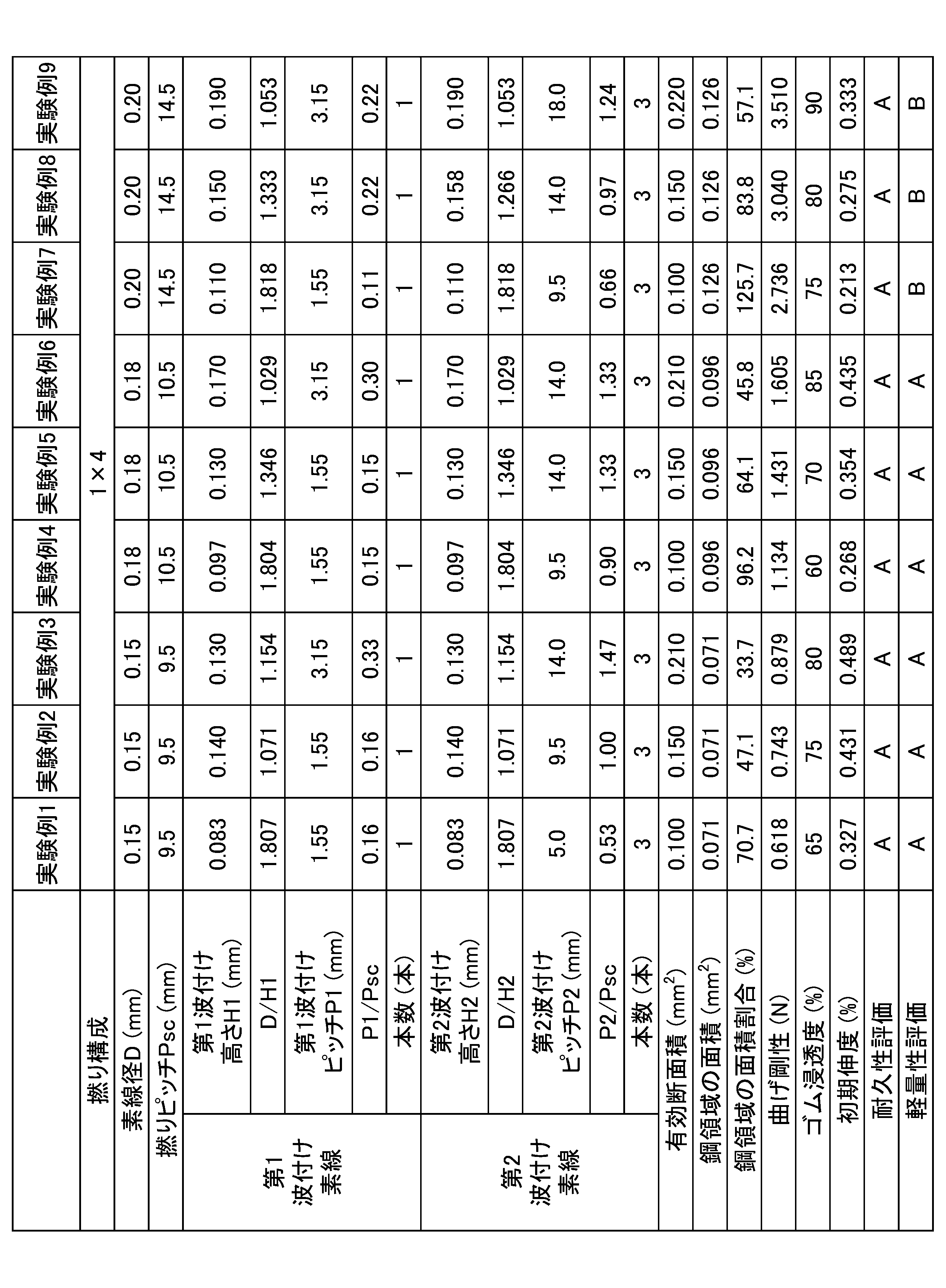

10 スチールコード
100 外表面
11 素線
11A 素線
11B 素線
11C 素線
11D 素線
OA 中心
OB 中心
OC 中心
OD 中心
LO1 共通接線
LO2 共通接線
LO3 共通接線
LO4 共通接線
LI1 線分
LI2 線分
LI3 線分
LI4 線分
111 線材
112 ブラスめっき膜
12 隙間
13 複合領域
14 鋼が分布した領域
D 素線径
20 コード-ゴム複合体
21 ゴム
X X軸
Y Y軸
Z Z軸
30 波付け素線
300 第1波付け素線
310 第2波付け素線
30A 端部
31 屈曲部
31A 屈曲部(第1点、第4点)
31B 屈曲部(第2点、第5点)
31C 屈曲部(第3点、第6点)
LA 直線
32 非屈曲部
H 波付け高さ
H1 第1波付け高さ
H2 第2波付け高さ
P 波付けピッチ
P1 第1波付けピッチ
P2 第2波付けピッチ
S 平面
40 コード-ゴム複合体
400 上面
41 ゴム
t1 ゴム厚み
t2 ゴム厚み
50 タイヤ
51 トレッド部
52 サイドウォール部
53 ビード部
54 インナーライナー
55 カーカス
56 ベルト層
57 ビードワイヤー
CL センターライン
60 試験体
601 第1端部
602 第2端部
611 支持治具
612 支持治具
613 押圧治具
62 ブロック矢印
L601 距離
L602 距離
70 試験体
71 第1ローラー
72 第2ローラー
73 第3ローラー
74 矢印
10
31B Bent part (2nd point, 5th point)
31C Bend part (3rd point, 6th point)
Claims (9)
前記素線の素線径が0.15mm以上0.20mm以下であり、
ゴム中に埋設した場合の、前記スチールコードの長手と垂直な断面において、
前記スチールコードの外表面と接する、隣接する前記素線の間の共通接線と、前記スチールコードの前記外表面に沿って隣接する前記素線の中心間を結ぶ線分と、で囲まれた領域を複合領域とし、前記複合領域の面積を有効断面積と定義した場合に、
前記有効断面積が0.099mm2以上0.224mm2以下である、スチールコード。 A steel cord having a 1×4 structure in which four wires are twisted together,
The wire has a diameter of 0.15 mm or more and 0.20 mm or less,
When embedded in rubber, in a cross section perpendicular to the longitudinal direction of the steel cord,
When a region surrounded by a common tangent line between adjacent wires that is in contact with the outer surface of the steel cord and a line segment that connects centers of adjacent wires along the outer surface of the steel cord is defined as a composite region, and an area of the composite region is defined as an effective cross-sectional area,
The effective cross-sectional area of the steel cord is 0.099 mm2 or more and 0.224 mm2 or less.
前記第1波付け素線の長手に沿って連続する3つの前記第1屈曲部を、第1点、第2点、第3点とし、
前記第1点、前記第3点のうち前記第2点に近い前記第1波付け素線の端部を通る直線と、前記第2点との間の最短距離を第1波付け高さと定義した場合に、
前記第1波付け高さに対する、前記素線径の割合が1.029以上1.818以下である、請求項1または請求項2に記載のスチールコード。 At least one of the wires is a first corrugated wire having a first bent portion and a first non-bent portion repeatedly along a longitudinal direction thereof,
The three first bent portions successive along the length of the first corrugated wire are defined as a first point, a second point, and a third point,
When the shortest distance between a straight line passing through an end of the first corrugated wire that is closest to the second point among the first point and the third point and the second point is defined as a first corrugation height,
3. The steel cord according to claim 1, wherein a ratio of the wire diameter to the first corrugation height is 1.029 or greater and 1.818 or less.
前記スチールコードの撚りピッチに対する、前記第1波付け素線の前記第1波付けピッチの割合が0.09以上0.35以下である、請求項3に記載のスチールコード。 When the distance between the first point and the third point of the first corrugated wire is defined as a first corrugation pitch,
4. The steel cord according to claim 3, wherein a ratio of the first corrugation pitch of the first corrugated wire to a twist pitch of the steel cord is 0.09 or more and 0.35 or less.
前記第2波付け素線の長手に沿って連続する3つの前記第2屈曲部を、第4点、第5点、第6点とし、
前記第4点、前記第6点のうち前記第5点に近い前記第2波付け素線の端部を通る直線と、前記第5点との間の最短距離を第2波付け高さ、前記第2波付け素線の前記第4点と前記第6点との間の距離を第2波付けピッチと定義した場合に、
前記第2波付け素線は、前記第2波付け高さに対する、前記素線径の割合が1.029以上1.818以下であり、
前記スチールコードの撚りピッチに対する、前記第2波付け素線の前記第2波付けピッチの割合が0.50以上1.50以下である、請求項3または請求項4に記載のスチールコード。 Among the four wires, at least one of the wires excluding the first corrugated wire is a second corrugated wire having second bent portions and second non-bent portions repeatedly along a longitudinal direction thereof,
The three second bent portions successive along the length of the second corrugated wire are a fourth point, a fifth point, and a sixth point,
When the shortest distance between the fifth point and a straight line passing through an end of the second corrugated wire that is closest to the fifth point among the fourth point and the sixth point is defined as a second corrugation height, and the distance between the fourth point and the sixth point of the second corrugated wire is defined as a second corrugation pitch,
The second corrugated wire has a ratio of the wire diameter to the second corrugation height of 1.029 or more and 1.818 or less,
5. The steel cord according to claim 3, wherein a ratio of the second corrugation pitch of the second corrugated wire to a twist pitch of the steel cord is 0.50 or more and 1.50 or less.
前記ゴムに埋設された、請求項1から請求項7のいずれか1項に記載されたスチールコードと、を含む、コード-ゴム複合体。 Rubber and
A cord-rubber composite comprising: the steel cord according to any one of claims 1 to 7 embedded in the rubber.
Priority Applications (3)
| Application Number | Priority Date | Filing Date | Title |
|---|---|---|---|
| JP2024543191A JP7670245B1 (en) | 2023-06-08 | 2024-02-19 | Steel cord, cord-rubber composite, tire |
| DE112024001258.2T DE112024001258T5 (en) | 2023-06-08 | 2024-02-19 | Steel cord, cord-rubber composite and tires |
| CN202480028007.6A CN121002251A (en) | 2023-06-08 | 2024-02-19 | Steel cord, cord-rubber composite, tire |
Applications Claiming Priority (2)
| Application Number | Priority Date | Filing Date | Title |
|---|---|---|---|
| JP2023-094993 | 2023-06-08 | ||
| JP2023094993 | 2023-06-08 |
Publications (1)
| Publication Number | Publication Date |
|---|---|
| WO2024252735A1 true WO2024252735A1 (en) | 2024-12-12 |
Family
ID=93795196
Family Applications (1)
| Application Number | Title | Priority Date | Filing Date |
|---|---|---|---|
| PCT/JP2024/005840 Ceased WO2024252735A1 (en) | 2023-06-08 | 2024-02-19 | Steel cord, cord-rubber composite, and tire |
Country Status (4)
| Country | Link |
|---|---|
| JP (1) | JP7670245B1 (en) |
| CN (1) | CN121002251A (en) |
| DE (1) | DE112024001258T5 (en) |
| WO (1) | WO2024252735A1 (en) |
Families Citing this family (1)
| Publication number | Priority date | Publication date | Assignee | Title |
|---|---|---|---|---|
| CN121723797B (en) * | 2026-02-26 | 2026-04-28 | 山东兴达轮胎有限公司 | Method for improving weight simulation calculation precision of engineering tire |
Citations (5)
| Publication number | Priority date | Publication date | Assignee | Title |
|---|---|---|---|---|
| JPS62125084A (en) * | 1986-10-31 | 1987-06-06 | 株式会社ブリヂストン | Metal cord |
| JPH05140881A (en) * | 1991-11-21 | 1993-06-08 | Sumitomo Rubber Ind Ltd | Pneumatic tire |
| JP2000203213A (en) * | 1999-01-08 | 2000-07-25 | Hankook Tire Mfg Co Ltd | Radial tire for passenger cars and light trucks having a carcass part to which steel code is applied |
| WO2018142691A1 (en) * | 2017-02-01 | 2018-08-09 | 栃木住友電工株式会社 | Tier |
| JP2018178332A (en) * | 2017-04-20 | 2018-11-15 | 栃木住友電工株式会社 | Steel cord, tire |
Family Cites Families (3)
| Publication number | Priority date | Publication date | Assignee | Title |
|---|---|---|---|---|
| JP3070260B2 (en) * | 1991-06-21 | 2000-07-31 | 住友電気工業株式会社 | Apparatus and method for producing metal cord for reinforcing rubber articles |
| JP4822597B2 (en) | 2001-03-21 | 2011-11-24 | 金井 宏彰 | Steel cords and tires for tire reinforcement |
| JP2023094993A (en) | 2021-12-24 | 2023-07-06 | 太陽誘電株式会社 | Manufacturing method for multilayer ceramic electronic component |
-
2024
- 2024-02-19 CN CN202480028007.6A patent/CN121002251A/en active Pending
- 2024-02-19 JP JP2024543191A patent/JP7670245B1/en active Active
- 2024-02-19 DE DE112024001258.2T patent/DE112024001258T5/en active Pending
- 2024-02-19 WO PCT/JP2024/005840 patent/WO2024252735A1/en not_active Ceased
Patent Citations (5)
| Publication number | Priority date | Publication date | Assignee | Title |
|---|---|---|---|---|
| JPS62125084A (en) * | 1986-10-31 | 1987-06-06 | 株式会社ブリヂストン | Metal cord |
| JPH05140881A (en) * | 1991-11-21 | 1993-06-08 | Sumitomo Rubber Ind Ltd | Pneumatic tire |
| JP2000203213A (en) * | 1999-01-08 | 2000-07-25 | Hankook Tire Mfg Co Ltd | Radial tire for passenger cars and light trucks having a carcass part to which steel code is applied |
| WO2018142691A1 (en) * | 2017-02-01 | 2018-08-09 | 栃木住友電工株式会社 | Tier |
| JP2018178332A (en) * | 2017-04-20 | 2018-11-15 | 栃木住友電工株式会社 | Steel cord, tire |
Also Published As
| Publication number | Publication date |
|---|---|
| CN121002251A (en) | 2025-11-21 |
| JP7670245B1 (en) | 2025-04-30 |
| JPWO2024252735A1 (en) | 2024-12-12 |
| DE112024001258T5 (en) | 2026-04-23 |
Similar Documents
| Publication | Publication Date | Title |
|---|---|---|
| JP7367899B1 (en) | Steel cord, cord-rubber composite, tire | |
| CN102906329B (en) | Triple-layered metal cord rubberised in situ by an unsaturated thermoplastic elastomer | |
| US9610806B2 (en) | Tire-reinforcing steel cord and radial tire using the same | |
| AU2002233673B2 (en) | Steel wire and steel cord for reinforcing rubber article, and tire | |
| CN104010832A (en) | Pneumatic radial tire | |
| JP7670245B1 (en) | Steel cord, cord-rubber composite, tire | |
| JP2006507414A (en) | Flat helically wound tire cord | |
| KR101152415B1 (en) | A steel cord and method for manufacturing of it | |
| CN114537047B (en) | Belted and tire | |
| JP7540621B1 (en) | Steel cord, cord-rubber composite, and tire | |
| WO2024176640A1 (en) | Steel cord, cord-rubber composite, and tire | |
| WO2026009644A1 (en) | Cord-rubber composite and tire | |
| WO2025047070A1 (en) | Steel cord and tire | |
| JP7581606B2 (en) | Method for manufacturing rubber composite and method for manufacturing tire | |
| CN120826509A (en) | Cord-rubber composite, method for producing cord-rubber composite, and tire | |
| JP7419644B2 (en) | Belt laminates, tires | |
| JP2009001924A (en) | Steel cord for reinforcing rubber article and pneumatic tire | |
| JPH1088488A (en) | Steel cords for rubber reinforcement and radial tires | |
| JPH04308287A (en) | Steel cord for reinforcing rubber article | |
| JP2017202706A (en) | Rubber-cord composite and pneumatic tire including the same | |
| JP4248007B2 (en) | Steel cord for tire reinforcement | |
| JP2597836Y2 (en) | Steel cord for reinforcing rubber products | |
| WO2026004233A1 (en) | Metal cord, composite cord, cord-rubber composite, and rubber product | |
| JP5692749B2 (en) | Steel cords for rubber article reinforcement and rubber-steel cord composites | |
| JPH0535888U (en) | Steel cord for reinforcing rubber products |
Legal Events
| Date | Code | Title | Description |
|---|---|---|---|
| WWE | Wipo information: entry into national phase |
Ref document number: 2024543191 Country of ref document: JP |
|
| 121 | Ep: the epo has been informed by wipo that ep was designated in this application |
Ref document number: 24818974 Country of ref document: EP Kind code of ref document: A1 |
|
| WWE | Wipo information: entry into national phase |
Ref document number: 2501007386 Country of ref document: TH |
|
| WWE | Wipo information: entry into national phase |
Ref document number: 112024001258 Country of ref document: DE |