WO2024252735A1 - Câble d'acier, composite câble-caoutchouc et pneu - Google Patents
Câble d'acier, composite câble-caoutchouc et pneu Download PDFInfo
- Publication number
- WO2024252735A1 WO2024252735A1 PCT/JP2024/005840 JP2024005840W WO2024252735A1 WO 2024252735 A1 WO2024252735 A1 WO 2024252735A1 JP 2024005840 W JP2024005840 W JP 2024005840W WO 2024252735 A1 WO2024252735 A1 WO 2024252735A1
- Authority
- WO
- WIPO (PCT)
- Prior art keywords
- cord
- rubber
- steel cord
- point
- wire
- Prior art date
- Legal status (The legal status is an assumption and is not a legal conclusion. Google has not performed a legal analysis and makes no representation as to the accuracy of the status listed.)
- Ceased
Links
Images


Classifications
-
- B—PERFORMING OPERATIONS; TRANSPORTING
- B60—VEHICLES IN GENERAL
- B60C—VEHICLE TYRES; TYRE INFLATION; TYRE CHANGING; CONNECTING VALVES TO INFLATABLE ELASTIC BODIES IN GENERAL; DEVICES OR ARRANGEMENTS RELATED TO TYRES
- B60C9/00—Reinforcements or ply arrangement of pneumatic tyres
-
- B—PERFORMING OPERATIONS; TRANSPORTING
- B60—VEHICLES IN GENERAL
- B60C—VEHICLE TYRES; TYRE INFLATION; TYRE CHANGING; CONNECTING VALVES TO INFLATABLE ELASTIC BODIES IN GENERAL; DEVICES OR ARRANGEMENTS RELATED TO TYRES
- B60C9/00—Reinforcements or ply arrangement of pneumatic tyres
- B60C9/18—Structure or arrangement of belts or breakers, crown-reinforcing or cushioning layers
- B60C9/20—Structure or arrangement of belts or breakers, crown-reinforcing or cushioning layers built-up from rubberised plies each having all cords arranged substantially parallel
-
- D—TEXTILES; PAPER
- D07—ROPES; CABLES OTHER THAN ELECTRIC
- D07B—ROPES OR CABLES IN GENERAL
- D07B1/00—Constructional features of ropes or cables
- D07B1/06—Ropes or cables built-up from metal wires, e.g. of section wires around a hemp core
Definitions
- This disclosure relates to steel cords, cord-rubber composites, and tires.
- Patent Document 1 discloses a steel cord for reinforcing tires, which is formed by twisting together 2 to 13 steel wires having a wire diameter of 0.23 to 0.50 mm, and which is characterized in that the cord has an elongation rate of 1.5 to 3.0% when subjected to a tensile load of 10% of the breaking load, and the value A shown in the following formula is 50 to 100 N/%.
- the steel cord of the present disclosure is a steel cord having a 1 ⁇ 4 structure in which four wires are twisted together,
- the wire has a diameter of 0.15 mm or more and 0.20 mm or less,
- When embedded in rubber, in a cross section perpendicular to the longitudinal direction of the steel cord When a region surrounded by a common tangent line between adjacent wires that is in contact with the outer surface of the steel cord and a line segment that connects centers of adjacent wires along the outer surface of the steel cord is defined as a composite region, and an area of the composite region is defined as an effective cross-sectional area,
- the effective cross-sectional area is equal to or greater than 0.099 mm 2 and equal to or less than 0.224 mm 2 .
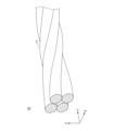
- FIG. 1 is a perspective view of a steel cord according to one embodiment of the present disclosure.
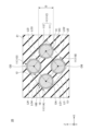
- FIG. 2 is a cross-sectional view of a plane perpendicular to the longitudinal direction of a steel cord according to one embodiment of the present disclosure, in a state in which the steel cord is embedded in rubber to form a cord-rubber composite.
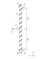
- FIG. 3 is an explanatory diagram of a corrugated wire.
- FIG. 4 is a cross-sectional view of a cord-rubber composite according to one embodiment of the present disclosure.
- FIG. 5 is a cross-sectional view of a tire according to one aspect of the disclosure.
- FIG. 6 is an explanatory diagram of a method for evaluating bending rigidity.
- FIG. 7 is an explanatory diagram of a method for evaluating durability.
- the thickness of the rubber in the cord-rubber composite is selected so that the steel cord can be embedded. For this reason, one possible way to make the cord-rubber composite lighter is to reduce the wire diameter of the wires that make up the steel cord, thereby reducing the outer diameter of the steel cord (cord diameter) and thus the thickness of the cord-rubber composite. However, if the wire diameter is reduced, the cord-rubber composite may be more susceptible to breakage when repeatedly bent, which could reduce its durability.
- the present disclosure aims to provide a stranded steel cord that, when applied to a cord-rubber composite, can reduce the weight of the cord-rubber composite while increasing its durability.
- This disclosure provides a stranded steel cord that, when applied to a cord-rubber composite, can reduce the weight of the cord-rubber composite while increasing its durability.
- a steel cord according to one embodiment of the present disclosure is a steel cord having a 1 ⁇ 4 structure in which four wires are twisted together,
- the wire has a diameter of 0.15 mm or more and 0.20 mm or less,
- When embedded in rubber, in a cross section perpendicular to the longitudinal direction of the steel cord When a region surrounded by a common tangent line between adjacent wires that is in contact with the outer surface of the steel cord and a line segment that connects centers of adjacent wires along the outer surface of the steel cord is defined as a composite region, and an area of the composite region is defined as an effective cross-sectional area,
- the effective cross-sectional area is equal to or greater than 0.099 mm 2 and equal to or less than 0.224 mm 2 .
- the outer diameter of the steel cord can be reduced.
- the thickness of the cord-rubber composite is selected so that the steel cord contained therein can be embedded. Therefore, by reducing the outer diameter of the steel cord according to one embodiment of the present disclosure, the thickness of the cord-rubber composite can also be reduced, and the cord-rubber composite and tires including the cord-rubber composite can be made lighter.
- the number of steel cords required to achieve the desired bending rigidity can be reduced for a cord-rubber composite including a steel cord according to one embodiment of the present disclosure. This allows for weight reduction of the cord-rubber composite and tires including the cord-rubber composite.
- the bending rigidity of the cord-rubber composite body can be set within an appropriate range, and durability can be improved.
- the ratio of the area of the region in which steel is distributed to the effective cross-sectional area in the cross section may be 30% or more and 128% or less.
- the area ratio of the steel region which is the ratio of the area of the region where steel is distributed to the effective cross-sectional area
- the bending rigidity of the cord-rubber composite can be increased when the cord-rubber composite is made.
- the area ratio of the steel region is set to 128% or less, the bending rigidity of the cord-rubber composite can be prevented from becoming excessively high when the cord-rubber composite is made. As a result, the durability of the cord-rubber composite can be particularly increased.
- At least one of the wires is a first corrugated wire having a first bent portion and a first non-bent portion repeatedly along a longitudinal direction,
- the three first bent portions successive along the length of the first corrugated wire are defined as a first point, a second point, and a third point,
- the first corrugated wire may have a ratio of the wire diameter to the first corrugation height of 1.029 or more and 1.818 or less.
- the ratio of wire diameter D to first corrugation height H1 By setting D/H1, the ratio of wire diameter D to first corrugation height H1, to 1.818 or less, the distance between adjacent wires in the steel cord is increased and the rubber penetration rate is increased when the steel cord is embedded in rubber to form a cord-rubber composite. As a result, when a cord-rubber composite is formed, the adhesion between the steel cord and rubber is improved, and the bending rigidity of the cord-rubber composite is increased.
- D/H1 1.029 By making D/H1 1.029 or more, it is possible to prevent the rubber penetration rate from becoming excessively high when the steel cord is embedded in rubber to form a cord-rubber composite. As a result, when a cord-rubber composite is formed, the adhesion between the steel cord and the rubber can be set in a particularly preferable range, and the bending rigidity of the cord-rubber composite can be prevented from becoming excessively high. As a result, the durability of the cord-rubber composite can be particularly improved.
- a ratio of the first corrugation pitch of the first corrugated wire to a twist pitch of the steel cord may be 0.09 or more and 0.35 or less.
- the ratio of the first corrugated pitch of the first corrugated wire to the twist pitch of the steel cord is 0.35 or less, the distance between adjacent wires in the steel cord is increased, and the rubber penetration rate is increased when the steel cord is embedded in rubber to form a cord-rubber composite.
- the adhesion between the steel cord and rubber is improved, and the bending rigidity of the cord-rubber composite is particularly increased.
- the ratio of the first corrugation pitch of the first corrugated wire to the twist pitch of the steel cord is 0.09 or more, it is possible to prevent the rubber penetration degree from becoming excessively high when the steel cord is embedded in rubber to form a cord-rubber composite.
- the adhesion between the steel cord and the rubber can be set to a particularly preferable range, and the bending rigidity of the cord-rubber composite can be prevented from becoming excessively high.
- the durability of the cord-rubber composite can be particularly improved.
- At least one of the four wires, excluding the first corrugated wire, is a second corrugated wire having second bent portions and second non-bent portions repeatedly along a longitudinal direction,
- the three second bent portions successive along the length of the second corrugated wire are a fourth point, a fifth point, and a sixth point
- the shortest distance between the fifth point and a straight line passing through an end of the second corrugated wire that is closest to the fifth point among the fourth point and the sixth point is defined as a second corrugation height
- the distance between the fourth point and the sixth point of the second corrugated wire is defined as a second corrugation pitch
- the second corrugated wire has a ratio of the wire diameter to the second corrugation height of 1.029 or more and 1.818 or less
- a ratio of the second corrugation pitch of the second corrugated wire to a twist pitch of the steel cord may be 0.50 or more and 1.50 or less.
- the ratio of wire diameter D to second corrugation height H2, to 1.818 or less By setting D/H2, the ratio of wire diameter D to second corrugation height H2, to 1.818 or less, the distance between adjacent wires in the steel cord is increased, and the rubber penetration rate is increased when the steel cord is embedded in rubber to form a cord-rubber composite. As a result, when a cord-rubber composite is formed, the adhesion between the steel cord and rubber is improved, and the bending rigidity of the cord-rubber composite is increased.
- D/H2 1.029 By making D/H2 1.029 or more, it is possible to prevent the rubber penetration rate from becoming excessively high when the steel cord is embedded in rubber to form a cord-rubber composite.
- the adhesion between the steel cord and the rubber can be set in a particularly preferable range, and the bending rigidity of the cord-rubber composite can be prevented from becoming excessively high.
- the durability of the cord-rubber composite can be particularly improved.
- the ratio of the second corrugation pitch of the second corrugated wire to the twist pitch of the steel cord (P2/Psc) to 1.50 or less, the distance between adjacent wires in the steel cord can be increased, and the rubber penetration rate can be increased when the steel cord is embedded in rubber to form a cord-rubber composite. This allows the effective cross-sectional area to be increased.
- the initial elongation may be 0.20% or more and 0.50% or less.
- the initial elongation 0.20% or more it is possible to improve the impact resistance, which is the ability to prevent the steel cord from breaking when a force perpendicular to the longitudinal direction of the steel cord is applied.
- the rubber penetration rate of the steel cord may be 60% or more.
- the adhesion between the steel cord and the rubber can be improved when a cord-rubber composite is made, and the bending rigidity of the cord-rubber composite can be increased.
- a cord-rubber composite according to one embodiment of the present disclosure comprises a rubber, and a steel cord according to any one of (1) to (7) embedded in the rubber.
- the cord-rubber composite according to one aspect of the present disclosure can reduce the thickness and weight of the cord-rubber composite or a tire using the cord-rubber composite. Furthermore, the cord-rubber composite according to one aspect of the present disclosure can increase the durability of the cord-rubber composite or a tire using the cord-rubber composite.
- a tire according to one embodiment of the present disclosure includes a steel cord according to any one of (1) to (7).
- the thickness of the belt layer can be reduced, making the tire including the belt layer lighter, and reducing the rolling resistance of the tire.
- a tire according to one aspect of the present disclosure can be made to have excellent durability.
- Fig. 1 is a perspective view of a steel cord 10 of this embodiment.
- Fig. 2 is a cross-sectional view of a plane perpendicular to the longitudinal direction of the steel cord 10 in a state in which the steel cord 10 of this embodiment is embedded in rubber 21 to form a cord-rubber composite 20.
- the Y axis in Figs. 1 and 2 is an axis along the longitudinal direction of the steel cord 10.
- the XZ plane in Figs. 1 and 2 is a plane perpendicular to the longitudinal direction of the steel cord 10.
- the steel cord 10 of this embodiment is a stranded steel cord formed by stranding together four wires 11, that is, wires 11A, 11B, 11C, and 11D (see FIG. 2 ).
- the four wires 11 are twisted together in a spiral shape along the longitudinal direction of the steel cord 10, as shown in FIG.
- the steel cord 10 of the present embodiment may have a 1 ⁇ 4 structure, which is a single-twist structure.
- a single-twist structure such as a 1 ⁇ N structure, means a structure in which N element wires 11 are twisted together to form a single layer (one layer).
- the single layer means a structure in which the element wires 11 are arranged in a row along the circumference of a circle in a cross section perpendicular to the longitudinal direction of the steel cord 10.
- the wire diameter D (see FIG. 2) of the wire 11 of the steel cord 10 of the present embodiment can be set to 0.15 mm or more and 0.20 mm or less.
- the outer diameter of the steel cord 10 can be reduced.
- the thickness of the cord-rubber composite is selected so that the steel cord 10 contained therein can be embedded. Therefore, by reducing the outer diameter of the steel cord 10 in this embodiment, the thickness of the cord-rubber composite using the steel cord 10 can also be reduced, making it possible to reduce the weight of the cord-rubber composite and tires including the cord-rubber composite.
- the wire 11 of the steel cord 10 of this embodiment may be composed of only a wire rod 111, or may have a brass plating film 112 on its surface (see FIG. 2). Specifically, the wire 11 may have the wire rod 111 and the brass plating film 112 covering the wire rod 111.
- the wire 111 may be, for example, a steel wire, and a high carbon steel wire may also be used.
- the brass plating film 112 may include copper (Cu) and zinc (Zn). As shown in FIG. 2, the brass plating film 112 may be disposed so as to cover the side surface of the wire 111.
- the adhesive layer thus produced can improve the initial adhesive performance between the steel cord 10 and the rubber 21.
- Initial adhesive performance refers to the adhesive performance between the steel cord 10 and the rubber 21 immediately after vulcanization during the manufacture of the cord-rubber composite or a tire that includes the cord-rubber composite.
- the zinc contained in the brass plating film 112 is thought to promote and control the reaction that forms the adhesive layer.
- the brass plating film 112 may contain elements other than copper and zinc.
- the brass plating film 112 may further contain one or more elements selected from cobalt (Co), nickel (Ni), tin (Sn), iron (Fe), and manganese (Mn).
- the additive elements cobalt, nickel, tin, iron, and manganese have a greater tendency to ionize than copper. Therefore, when the brass plating film 112 contains an additive element in addition to copper and zinc, the brass plating film 112 functions as a sacrificial anticorrosion agent or can make the composite potential of copper and zinc more noble. Therefore, when the brass plating film 112 contains an additive element, the corrosion resistance of the steel cord 10 can be improved.
- (2-3) Corrugated Wire Some or all of the wires 11 contained in the steel cord 10 of this embodiment may be corrugated wires 30 having bent portions 31 and non-bent portions 32 repeatedly along the length as shown in Fig. 3. By making some or all of the wires 11 corrugated, the penetration degree of rubber into the steel cord 10, the elongation characteristics of the steel cord 10, etc. can be adjusted and selected.
- the shape and size of the corrugation can be selected according to the characteristics to be adjusted by the corrugated wire, and are not particularly limited.
- first corrugated wire For example, in the steel cord 10 of the present embodiment, at least one of the wires 11 may be a first corrugated wire having first bent portions and first non-bent portions alternately along the longitudinal direction.
- FIG. 3 shows the first corrugated wire 300 placed on a plane S such that the plane S is perpendicular to a plane passing through the first bent portion 31, which is the bent portion, and the first non-bent portion 32, which is the non-bent portion.
- the first bends which are three consecutive bends 31 along the length of the first corrugated wire 300, are referred to as the first point, second point, and third point.
- the first point is bend 31A
- the second point is bend 31B
- the third point is bend 31C.
- the shortest distance between the second point and a straight line LA passing through the end 30A of the first corrugated wire 300 that is closest to the second point among the first and third points is defined as the first corrugation height H1.
- the first corrugation height H1 can also be defined as the distance between the straight line LA and a straight line LB that is parallel to the straight line LA that passes through the end 30B of the first corrugated wire 300 that is closest to the first and third points among the second points.
- the shortest distance between the first bends, which are the bends 31, along the vertical direction of the plane S can also be defined as the first corrugation height H1. That is, for example, the shortest length along the vertical direction of the plane S between the bend 31A, which is the first point, or the bend 31C, which is the third point, and the bend 31B, which is the second point, can also be defined as the first corrugation height H1. Therefore, in FIG. 3, the first corrugation height H1 is the distance along the vertical direction of the plane S between the opposing parts of the first corrugated wire 300 at the bends 31A and 31B, for example.
- the first corrugated wire 300 can have a ratio D/H1, which is the ratio of the wire diameter D (see Figure 2) to the first corrugation height H1, of 1.029 or more and 1.818 or less.
- the distance between adjacent wires 11 in the steel cord 10 can be increased, and the degree of rubber penetration can be increased when the steel cord 10 is embedded in rubber to form a cord-rubber composite.
- the adhesion between the steel cord 10 and the rubber can be improved, and the bending rigidity of the cord-rubber composite can be increased.
- D/H1 1.029 By making D/H1 1.029 or more, it is possible to prevent the rubber penetration rate from becoming excessively high when the steel cord 10 is embedded in rubber to form a cord-rubber composite. Therefore, when a cord-rubber composite is formed, the adhesion between the steel cord 10 and the rubber can be set in a particularly preferable range, and the bending rigidity of the cord-rubber composite can be prevented from becoming excessively high. As a result, the durability of the cord-rubber composite can be particularly improved.
- the distance between the first bend 31A, which is the first point, and the third bend 31C, which is the third point, of the first corrugated wire 300 is defined as the first corrugated pitch P1.
- the distance between the first bends, which are adjacent bends 31 along the plane S when the first corrugated wire 300 is placed on the plane S can also be defined as the first corrugated pitch P1.
- the distance between the first bends, which is the distance along the plane S, between the first bend 31A, which is the first point, and the third bend 31C, which is the distance between the first bends can be defined as the first corrugated pitch P1.
- P1/Psc which is the ratio of the first corrugation pitch P1 of the first corrugated wire 300 to the twist pitch Psc of the steel cord, may be 0.09 or more and 0.35 or less, 0.10 or more and 0.34 or less, 0.11 or more and 0.33 or less, or 0.15 or more and 0.33 or less.
- the distance between adjacent wires 11 in the steel cord 10 can be increased, and the rubber penetration can be increased when the steel cord 10 is embedded in rubber to form a cord-rubber composite.
- P1/Psc the distance between adjacent wires 11 in the steel cord 10
- the rubber penetration can be increased when the steel cord 10 is embedded in rubber to form a cord-rubber composite.
- the adhesion between the steel cord 10 and the rubber can be improved, and the bending rigidity of the cord-rubber composite can be increased.
- the steel cord 10 of the present embodiment may have, as the corrugated wires 30, in addition to the first corrugated wires 300, a second corrugated wire 310 having different corrugation conditions.
- the number of each corrugated wire is not particularly limited, and the number of the first corrugated wires 300 and the number of the second corrugated wires 310 may be the same.
- the steel cord 10 of this embodiment may contain more first corrugated wires 300 than the number of the second corrugated wires 310.
- the steel cord 10 of this embodiment may contain more second corrugated wires 310 than the number of the first corrugated wires 300.
- At least one of the four wires 11, excluding the first corrugated wire 300, can be a second corrugated wire 310 having second bent portions and second non-bent portions repeatedly along the length.
- the second corrugated wire 310 can be configured in the same way as the first corrugated wire 300, except for the different corrugation conditions, so an example configuration will be explained using Figure 3.
- FIG. 3 shows the second corrugated wire 310 placed on plane S such that plane S is perpendicular to a plane passing through the second bent portion, which is bent portion 31, and the second non-bent portion, which is non-bent portion 32.
- the second bends which are three consecutive bends 31 along the length of the second corrugated wire 310, are designated as the fourth point, fifth point, and sixth point.
- the fourth point is bend 31A
- the fifth point is bend 31B
- the sixth point is bend 31C.
- the shortest distance between the fifth point and the straight line LA passing through the end of the second corrugated wire 310 closest to the fifth point among the fourth and sixth points is defined as the second corrugation height H2.
- the second corrugation height H2 can also be defined as the distance between the straight line LA and the straight line LB parallel to the straight line LA passing through the end 30B of the second corrugated wire 310 closest to the fourth and sixth points among the fifth points.
- the second corrugation height H2 is the distance along the vertical direction of the plane S between the opposing portions of the second corrugated wire 310 at the bends 31A and 31B, for example.
- the second corrugated wire 310 can have a ratio D/H2, which is the ratio of the wire diameter D (see Figure 2) to the second corrugation height H2, of 1.029 or more and 1.818 or less.
- the distance between adjacent wires 11 in the steel cord 10 can be increased, and the degree of rubber penetration can be increased when the steel cord 10 is embedded in rubber to form a cord-rubber composite.
- the adhesion between the steel cord 10 and the rubber can be improved, and the bending rigidity of the cord-rubber composite can be increased.
- D/H2 1.029 By making D/H2 1.029 or more, it is possible to prevent the rubber penetration rate from becoming excessively high when the steel cord 10 is embedded in rubber to form a cord-rubber composite. Therefore, when a cord-rubber composite is formed, the adhesion between the steel cord 10 and the rubber can be set in a particularly preferable range, and the bending rigidity of the cord-rubber composite can be prevented from becoming excessively high. As a result, the durability of the cord-rubber composite can be particularly improved.
- the distance between the bend 31A, which is the fourth point of the second corrugated wire 310, and the bend 31C, which is the sixth point, is defined as the second corrugation pitch P2.
- the distance between the second bends, which are adjacent bends 31 along the plane S of the second corrugated wire 310, can also be defined as the second corrugation pitch P2.
- the distance between the bend 31A, which is the fourth point, and the bend 31C, which is the sixth point, which is the distance between the second bends along the plane S can be defined as the second corrugation pitch P2.
- P2/Psc which is the ratio of the second corrugation pitch P2 of the second corrugated wire 310 to the twist pitch Psc of the steel cord, may be, for example, 0.50 or more and 1.50 or less, 0.52 or more and 1.48 or less, or 0.53 or more and 1.47 or less.
- the distance between adjacent wires 11 in the steel cord 10 can be increased, and the rubber penetration rate can be increased when the steel cord is embedded in rubber to form a cord-rubber composite. This allows the effective cross-sectional area to be increased.
- the effective cross-sectional area will be explained in "(3) Structure of steel cord embedded in rubber".
- durability refers to the ability to prevent the cord-rubber composite from breaking when it is repeatedly bent, and can be evaluated based on the number of times the cord-rubber composite can be repeatedly bent before breaking.
- the composite region 13 is defined as the region surrounded by the common tangent LO1, the common tangent LO2, the common tangent LO3, the common tangent LO4, the line segments LI1, LI2, LI3, and LI4 in a cross section perpendicular to the longitudinal direction of the steel cord 10 when the steel cord 10 is embedded in the rubber 21.
- the common tangent LO1, the common tangent LO2, the common tangent LO3, and the common tangent LO4 are all common tangents between adjacent wires 11 that are in contact with the outer surface 100 of the steel cord 10.
- the outer surface 100 of the steel cord 10 refers to the surface exposed to the outside of the steel cord 10.
- tangent LO1 is a common tangent between wire 11A and wire 11B.
- Tangent LO2 is a common tangent between wire 11B and wire 11C.
- Tangent LO3 is a common tangent between wire 11C and wire 11D.
- Tangent LO4 is a common tangent between wire 11D and wire 11A.
- line segments LI1, LI2, LI3, and LI4 are all line segments that connect the centers of adjacent wires 11 along the outer surface 100 of the steel cord 10.
- line segment LI1 is a line segment connecting center OA of wire 11A and center OB of wire 11B.
- Line segment LI2 is a line segment connecting center OB of wire 11B and center OC of wire 11C.
- Line segment LI3 is a line segment connecting center OC of wire 11C and center OD of wire 11D.
- Line segment LI4 is a line segment connecting center OD of wire 11D and center OA of wire 11A.
- the composite region 13 is the region in which the wires 11 of the steel cord 10 and the rubber 21 are arranged when the steel cord 10 is embedded in the rubber 21. For this reason, the composite region 13 is considered to be a region in which the steel cord 10 and the rubber are evaluated as being integrated, and the effective cross-sectional area, which is the area of the composite region 13, correlates with the bending rigidity of the cord-rubber composite 20.
- the steel cord 10 of this embodiment can have an effective cross-sectional area of 0.099 mm2 or more and 0.224 mm2 or less.
- the effective cross-sectional area By setting the effective cross-sectional area to 0.099 mm2 or more and 0.224 mm2 or less, the bending rigidity of the cord-rubber composite can be set in an appropriate range, and durability can be improved. From the viewpoint of setting the bending rigidity of the cord-rubber composite in a particularly appropriate range and improving durability, the effective cross-sectional area may be 0.100 mm2 or more and 0.222 mm2 or less, 0.100 mm2 or more and 0.220 mm2 or less, or 0.100 mm2 or more and 0.210 mm2 or less.
- the ratio of the area of the region where steel is distributed to the effective cross-sectional area in a cross section perpendicular to the longitudinal direction of the steel cord 10, i.e., the area ratio of the steel region may be 30% or more and 128% or less.
- the steel-distributed region 14 is the region where the wire 111 of the wire 11 is arranged. If the wire 11 does not have the brass plating film 112, the steel-distributed region 14 is the region where the wire 11 is arranged. Since the brass plating film 112 is usually very thin, the steel-distributed region 14 may be the region where the wire 11 is arranged even if the wire 11 has the brass plating film 112.
- the area ratio of the steel region can also be said to be the ratio of the cross-sectional area of the wire 111 or the cross-sectional area of the strand 11 to the effective cross-sectional area, which is the area of the composite region 13.
- the bending rigidity of the cord-rubber composite can be increased when it is made into a cord-rubber composite. Also, by making the area ratio of the steel region 128% or less, the bending rigidity of the cord-rubber composite can be prevented from becoming excessively high when it is made into a cord-rubber composite. As a result, the durability of the cord-rubber composite can be particularly increased.
- the area ratio of the steel region may be 33% or more and 126% or less.
- (4) Characteristics of Steel Cord (4-1) Initial Elongation The steel cord 10 of the present embodiment may have an initial elongation of 0.20% or more and 0.50% or less.
- the impact resistance which is the ability to prevent the steel cord 10 from breaking when a force perpendicular to the longitudinal direction of the steel cord 10 is applied, can be improved.
- the initial elongation to 0.50% or less, it is possible to prevent the wires 11 from being pulled together by the tension applied during molding and vulcanization of the rubber, such as when manufacturing a cord-rubber composite, and to prevent the gaps 12 between the wires 11 from becoming smaller. This makes it possible to prevent a decrease in the degree of rubber penetration, such as when manufacturing a cord-rubber composite.
- the initial elongation of the steel cord of the present embodiment may be 0.21% or more and 0.49% or less, from the viewpoint of further increasing the impact resistance performance and the rubber penetration rate.
- (4-2) Rubber Penetration Degree The steel cord of the present embodiment may have a rubber penetration degree of 60% or more.
- the adhesion between the steel cord and the rubber can be improved when a cord-rubber composite is made, and the bending rigidity of the cord-rubber composite can be increased.
- the rubber penetration rate of the steel cord of this embodiment may be 60% or more and 100% or less, or 65% or more and 95% or less, from the viewpoint of setting the bending rigidity of the cord-rubber composite in a particularly optimal range when applied to the cord-rubber composite.
- the initial elongation and rubber penetration can be adjusted by selecting the number of corrugated wires in the steel cord 10, the corrugation height H of the corrugated wires 30, the corrugation pitch P, the twist pitch of the steel cord 10, etc.
- FIG. 4 shows a cross-sectional view of a cord-rubber composite 40 of this embodiment taken along a plane perpendicular to the longitudinal direction of the steel cord 10.
- the cord-rubber composite 40 of this embodiment can have rubber 41 and the steel cord 10 of this embodiment embedded in the rubber 41.
- the thickness of the cord-rubber composite 40 can be selected so that the steel cord 10 can be embedded in the rubber 41. Specifically, the rubber thickness t1 to be placed under the steel cord 10 and the rubber thickness t2 to be placed on the top of the steel cord 10 can be selected.
- the outer diameter of the steel cord 10 can be reduced by setting the wire diameter D (see FIG. 1) of the wires 11 within a predetermined range. Reducing the outer diameter of the steel cord 10 also reduces the thickness of the cord-rubber composite 40. As a result, by using the steel cord 10 according to one aspect of the present disclosure, the amount of rubber contained in the cord-rubber composite 40 of this embodiment can be reduced, making it possible to reduce the weight. Furthermore, the tire including the cord-rubber composite 40 of this embodiment can also be reduced in weight.
- the cord-rubber composite 40 including the steel cord 10 according to one embodiment of the present disclosure can achieve bending rigidity within an appropriate range, thereby improving durability.
- the cord-rubber composite 40 can contain a plurality of steel cords 10.
- the steel cords 10 contained in the cord-rubber composite 40 can be arranged such that the longitudinal direction of each steel cord 10 is aligned along the Y axis in Fig. 4.
- the plurality of steel cords 10 can be arranged along the width of the cord-rubber composite 40, i.e., along the X axis in Fig. 4.
- Multiple steel cords 10 may be arranged in parallel with each other.
- the details of the steel cord 10 have already been described, and therefore will not be described again.
- Rubber The rubber 41 of the cord-rubber composite 40 can be produced by molding a rubber composition and vulcanizing it as necessary.
- the specific composition of the rubber is not particularly limited and can be selected according to the application of various products, such as tires, to which the cord-rubber composite 40 is applied, and the required characteristics.
- the rubber can contain, for example, a rubber component, sulfur, and a vulcanization accelerator.
- the rubber component may contain at least one type selected from, for example, natural rubber (NR) and isoprene rubber (IR) in an amount of 60% by mass or more, 70% by mass or more, or even 100% by mass.
- NR natural rubber
- IR isoprene rubber
- the rubber components used in combination with natural rubber or isoprene rubber may be, for example, one or more selected from styrene-butadiene rubber (SBR), butadiene rubber (BR), ethylene-propylene-diene rubber (EPDM), chloroprene rubber (CR), butyl rubber (IIR), and acrylonitrile-butadiene rubber (NBR).
- SBR styrene-butadiene rubber
- BR butadiene rubber
- EPDM ethylene-propylene-diene rubber
- CR chloroprene rubber
- IIR butyl rubber
- NBR acrylonitrile-butadiene rubber
- sulfur used as a vulcanizing agent in the rubber industry can be used.
- the amount of sulfur in the rubber is not particularly limited, but may be, for example, 5 parts by mass or more and 8 parts by mass or less per 100 parts by mass of the rubber component.
- the ratio of sulfur to 5 parts by mass or more per 100 parts by mass of the rubber component, the crosslink density of the resulting rubber can be increased, and in particular the adhesive strength between the steel cord and the rubber can be increased. Also, by setting the ratio of sulfur to 8 parts by mass or less per 100 parts by mass of the rubber component, the sulfur can be dispersed particularly uniformly within the rubber, and blooming can be prevented from occurring.
- the vulcanization accelerator is not particularly limited, but may be, for example, a sulfenamide accelerator such as N,N'-dicyclohexyl-2-benzothiazolylsulfenamide, N-cyclohexyl-2-benzothiazolylsulfenamide, N-tert-butyl-2-benzothiazolylsulfenamide, or N-oxydiethylene-2-benzothiazolylsulfenamide.
- a sulfenamide accelerator such as N,N'-dicyclohexyl-2-benzothiazolylsulfenamide, N-cyclohexyl-2-benzothiazolylsulfenamide, N-tert-butyl-2-benzothiazolylsulfenamide, or N-oxydiethylene-2-benzothiazolylsulfenamide.
- a thiazole accelerator such as 2-mercaptobenzothiazole or di-2-benzothiazolyl disulfide, or a thiuram accelerator such as tetrabenzylthiuram disulfide, tetramethylthiuram disulfide, tetraethylthiuram disulfide, tetrakis(2-ethylhexyl)thiuram disulfide, or tetramethylthiuram monosulfide may be used.
- the rubber composition used in the cord-rubber composite 40 of this embodiment can be produced by kneading raw materials such as rubber components, heating them, and extruding them.
- the rubber of the cord-rubber composite 40 of this embodiment may contain one or more types selected from simple cobalt and compounds containing cobalt.
- Compounds containing cobalt include organic cobalt acids and inorganic cobalt acids.
- organic cobalt acid salt for example, one or more selected from cobalt naphthenate, cobalt stearate, cobalt neodecanoate, cobalt rosinate, cobalt versatate, cobalt tall oil acid, etc. can be used.
- the organic cobalt acid salt may be a composite salt in which part of the organic acid is replaced with boric acid.
- the inorganic cobalt acid may be, for example, one or more selected from cobalt chloride, cobalt sulfate, cobalt nitrate, cobalt phosphate, and cobalt chromate.
- the rubber may also contain any optional components other than the above rubber components, sulfur, vulcanization accelerator, cobalt, etc.
- the rubber may also contain well-known rubber additives such as reinforcing agents (carbon black, silica, etc.), wax, and antioxidants.
- ends refers to the number of steel cords 10 arranged per 50 mm width of the cord-rubber composite 40 in a cross section perpendicular to the longitudinal direction of the steel cords 10 of the cord-rubber composite 40. For this reason, in this specification, the unit of ends is "pieces/50 mm".
- the cord-rubber composite 40 of this embodiment may include steel cords 10 so that the ends are, for example, 30 cords/50 mm or more and 60 cords/50 mm or less.
- the ends of the cord-rubber composite 40 may be 36 cords/50 mm or more and 60 cords/50 mm or less, or 40 cords/50 mm or more and 60 cords/50 mm or less.
- the gaps between the steel cords 10 contained in the cord-rubber composite 40 can be reduced, allowing the steel cords to be arranged at a high density. This improves punching resistance, a property that prevents foreign objects from penetrating the cord-rubber composite 40.
- the bending rigidity of the cord-rubber composite 40 can be easily controlled within a desired range.
- the ends of the cord-rubber composite 40 By setting the ends of the cord-rubber composite 40 to 60 pieces/50 mm or less, the number of supply devices that supply steel cords during the production of the cord-rubber composite 40 can be reduced, thereby increasing productivity.
- the cord-rubber composite 40 of this embodiment uses the steel cord 10 according to one aspect of the present disclosure. This allows the thickness of the cord-rubber composite 40 to be reduced, making it possible to reduce the weight of the cord-rubber composite or a tire using the cord-rubber composite. Furthermore, the cord-rubber composite 40 of this embodiment allows the durability of the cord-rubber composite 40 or a tire using the cord-rubber composite 40 to be improved.
- the tire of this embodiment may include a steel cord 10 according to one aspect of the present disclosure.
- FIG. 5 shows a cross-sectional view of a tire 50 according to this embodiment taken along a plane perpendicular to the circumferential direction.
- FIG. 5 shows only the portion to the left of the center line (CL), the same structure continues to the right of the center line (CL) with the CL as an axis of symmetry.
- the tire 50 has a tread portion 51, a sidewall portion 52, and a bead portion 53.
- the tread portion 51 is the portion that comes into contact with the road surface.
- the bead portion 53 is located closer to the inner diameter of the tire 50 than the tread portion 51.
- the bead portion 53 is the portion that comes into contact with the rim of the vehicle's wheel.
- the sidewall portion 52 connects the tread portion 51 and the bead portion 53. When the tread portion 51 receives an impact from the road surface, the sidewall portion 52 elastically deforms and absorbs the impact.
- the tire 50 includes an inner liner 54, a carcass 55, a belt layer 56, and a bead wire 57.
- the inner liner 54 is made of rubber and seals the space between the tire 50 and the wheel.
- the carcass 55 forms the framework of the tire 50.
- the carcass 55 is made of organic fibers such as polyester, nylon, or rayon, or steel cords, and rubber.
- the bead wire 57 is provided in the bead portion 53.
- the bead wire 57 receives the tensile force acting on the carcass 55.
- the belt layer 56 tightens the carcass 55 to increase the rigidity of the tread portion 51.
- the tire 50 has two belt layers 56.
- the cord-rubber composite 40 according to one embodiment of the present disclosure can be used as the belt layer 56.
- the cord-rubber composite 40 has already been described, so a description thereof will be omitted.
- the belt layer 56 uses a cord-rubber composite 40 that includes a steel cord 10 according to one aspect of the present disclosure.
- the thickness of the belt layer 56 can be reduced, making the tire 50 including the belt layer 56 lighter, and reducing the rolling resistance of the tire.
- the tire 50 of this embodiment can be made to have excellent durability.
- the cord-rubber composite prepared in each experimental example was cut into a 30 mm x 50 mm test piece.
- the long side of the test piece, which is 50 mm long, was the side that ran along the length of the steel cord contained in the test piece.
- first end 601 and the second end 602 which are the ends of the width of the test piece 60, are supported from the underside by support jigs 611 and 612.
- the midpoint between support jigs 611 and 612 is pressed downward by pressing jig 613, as shown by block arrow 62.
- Distance L601 and distance L602 in FIG. 6 are equal.
- Distance L601 refers to the distance between the point where test body 60 contacts support jig 611 and the point where test body 60 contacts pressing jig 613.
- Distance L602 refers to the distance between the point where test body 60 contacts support jig 612 and the point where test body 60 contacts pressing jig 613.
- the bending rigidity is calculated by measuring the reaction force when the point pressed by the pressing tool 613 is displaced 1 mm along the block arrow 62.
- the test specimen 60 is arranged so that the longitudinal direction of the steel cord contained within the test specimen 60 is aligned with the Y axis in FIG. 6, that is, along the arrangement of the support jig 611, the pressing jig 613, and the support jig 612.
- the distance between the support jig 611 and the support jig 612 is 30 mm.
- the test specimen 60 is arranged so that its long side, which is 50 mm long, is aligned with the arrangement of the support jigs 611 and 612, i.e., the Y-axis in FIG. 6, and its short side, which is 30 mm long, is aligned with the X-axis perpendicular to the paper surface in FIG. (6) Rubber Penetration Degree From the cord-rubber composite produced in each experimental example, the steel cord was removed with a cutter knife.
- the ratio of the length of the rubber-covered portion to the 100 mm observation length along the center line of the exposed area that was left by removing the two adjacent wires is calculated as a percentage, and this is the rubber penetration rate.
- the center line is a line drawn along the length of the exposed area, passing through the center of the width perpendicular to the length of the exposed area.
- Initial Elongation is the percentage elongation when a load of 50 N is applied to a steel cord, and is evaluated using a tensile tester.
- the first distance L0 which is the distance between the chucks of the tensile testing machine, is set to 500 mm, and the steel cord manufactured in each experimental example is placed in the chuck.
- a load is applied to the steel cord to change the distance between the chucks, and the distance between the chucks when the load applied to the steel cord reaches 50 N is set as the second distance L1.
- the initial elongation of the steel cord is calculated using the following formula (B).
- the obtained test specimen 70 is placed on a first roller 71, a second roller 72, and a third roller 73, each having a roller diameter of 25 mm.
- the first roller 71, the second roller 72, and the third roller 73 are arranged along the longitudinal direction of the steel cord included in the test specimen 70.
- the position of each roller is adjusted so that the test specimen 70 located between the first roller 71 and the second roller 72 and the test specimen 70 located between the second roller 72 and the third roller 73 are parallel to each other, as shown in FIG. 7.
- a load of 29.4 N is applied along the longitudinal direction to the test specimen 70 placed on the first roller 71, the second roller 72, and the third roller 73. Then, the first roller 71, the second roller 72, and the third roller 73 are rotated to move the test specimen 70 in the direction indicated by the arrow 74 in FIG. 7. Next, the first roller 71, the second roller 72, and the third roller 73 are rotated in the reverse direction to move the test specimen 70 in the opposite direction to the arrow 74 in the figure.
- the above operations constitute one set, and this set of operations is repeated.
- the rotation speed of each roller is set so that the above reciprocating movement can be performed 100 times per minute. Then, the number of sets of the above reciprocating movement of the test specimen until the test specimen 70 breaks is counted.
- the evaluation result for the cord-rubber composite of Experimental Example 11 is set as the standard, i.e., 100, and the evaluation results measured for the cord-rubber composites of each Experimental Example are normalized and used as the durability index value.
- the durability index value is 110 or more, it is rated as A; if the durability index value is greater than 100 but less than 110, it is rated as B; and if the durability index value is 100 or less, it is rated as C.
- the cord-rubber composite When the rating is A, the cord-rubber composite is said to have particularly excellent durability, and the ratings decrease in the order of B and C. When the rating is A or B, the cord-rubber composite has high durability. (9) Evaluation of Light Weight The cord-rubber composite produced in each experimental example was cut into a 100 mm square and the weight was measured. The size here is the size as seen from the top surface 400 of the cord-rubber composite 40 shown in FIG. 4.
- the evaluation result of the cord-rubber composite in Experimental Example 11 is set as the standard, i.e., 100, and the weight measured in each experimental example is normalized and used as the index value for lightness.
- the lightness index value is less than 90, it is rated as A; if the lightness index value is between 90 and 100, it is rated as B; and if the lightness index value is 100 or more, it is rated as C.
- one first corrugated wire and three second corrugated wires corrugated as shown in Table 1 are prepared. All four wires have the same wire diameter D, which is the value shown in Table 1. Furthermore, all four wires 11 have a brass plating film 112 containing copper and zinc disposed on the surface of the wire material 111, which is a steel wire. The four wires are then twisted together to produce a stranded steel cord having a 1 x 4 structure.
- the evaluation results of the obtained steel cord are shown in Table 1.
- the steel cord of this experimental example is embedded in rubber so that the ends are 46 cords/50 mm, and a cord-rubber composite 40 having the structure shown in FIG. 4 is produced.
- the rubber is manufactured using a rubber composition containing a rubber component and additives.
- the rubber composition contains 100 parts by mass of natural rubber as the rubber component.
- the rubber composition also contains, as additives, 60 parts by mass of carbon black, 7 parts by mass of sulfur, 0.5 parts by mass of vulcanization accelerator, 8 parts by mass of zinc oxide, and 2 parts by mass of cobalt stearate as an organic cobalt acid per 100 parts by mass of the rubber component.
- the cord-rubber composite was prototyped in advance using the steel cord of this experimental example, and the thickness of the rubber was selected to allow for the variation in the position of the steel cord so that the steel cord 10 could be embedded.
- the evaluation results for the cord-rubber composite are shown in Table 1. [Experimental Examples 2 to 13] The wire diameters and corrugation conditions of the first corrugated wire and the second corrugated wire prepared were changed to the values shown in Tables 1 and 2. In addition, the twist pitch when twisting the four wires was changed.
- steel cords and cord-rubber composites were manufactured and evaluated using the same procedures and conditions as in Experimental Example 1.
- the steel cords of Experimental Examples 1 to 9 which have a wire diameter of 0.15 mm or more and 0.20 mm or less and an effective cross-sectional area of 0.099 mm2 or more and 0.224 mm2 or less, are evaluated as A or B in terms of durability and light weight.
- the steel cords of Experimental Examples 1 to 9 are stranded steel cords that, when applied to a cord-rubber composite, can reduce the weight of the cord-rubber composite while increasing its durability.
Landscapes
- Engineering & Computer Science (AREA)
- Mechanical Engineering (AREA)
- Ropes Or Cables (AREA)
- Tires In General (AREA)
Abstract
L'invention concerne un câble d'acier ayant une structure de 1 × 4 dans laquelle quatre fils d'élément sont torsadés, les fils d'élément ayant un diamètre de fil d'élément d'entre 0,15 mm et 0,20 mm inclus tous les deux, et, lorsque, dans une section transversale perpendiculaire à la direction longitudinale du câble d'acier incorporé dans du caoutchouc, une région encerclée par des lignes tangentes communes entre les fils d'élément adjacents les uns aux autres, les lignes tangentes communes étant en contact avec une surface externe du câble d'acier, et des segments de ligne reliant les centres des fils d'élément qui sont adjacents le long de la surface externe du câble d'acier sont définis comme étant une région composite, et l'aire de la région composite est définie comme étant une aire de section transversale efficace, l'aire de section transversale efficace est entre 0,099 mm2 et 0,224 mm2 inclus tous les deux.
Priority Applications (3)
| Application Number | Priority Date | Filing Date | Title |
|---|---|---|---|
| JP2024543191A JP7670245B1 (ja) | 2023-06-08 | 2024-02-19 | スチールコード、コード-ゴム複合体、タイヤ |
| DE112024001258.2T DE112024001258T5 (de) | 2023-06-08 | 2024-02-19 | Stahlcord, Cord-Gummi-Verbundwerkstoff und Reifen |
| CN202480028007.6A CN121002251A (zh) | 2023-06-08 | 2024-02-19 | 钢帘线、帘线-橡胶复合体、轮胎 |
Applications Claiming Priority (2)
| Application Number | Priority Date | Filing Date | Title |
|---|---|---|---|
| JP2023-094993 | 2023-06-08 | ||
| JP2023094993 | 2023-06-08 |
Publications (1)
| Publication Number | Publication Date |
|---|---|
| WO2024252735A1 true WO2024252735A1 (fr) | 2024-12-12 |
Family
ID=93795196
Family Applications (1)
| Application Number | Title | Priority Date | Filing Date |
|---|---|---|---|
| PCT/JP2024/005840 Ceased WO2024252735A1 (fr) | 2023-06-08 | 2024-02-19 | Câble d'acier, composite câble-caoutchouc et pneu |
Country Status (4)
| Country | Link |
|---|---|
| JP (1) | JP7670245B1 (fr) |
| CN (1) | CN121002251A (fr) |
| DE (1) | DE112024001258T5 (fr) |
| WO (1) | WO2024252735A1 (fr) |
Families Citing this family (1)
| Publication number | Priority date | Publication date | Assignee | Title |
|---|---|---|---|---|
| CN121723797B (zh) * | 2026-02-26 | 2026-04-28 | 山东兴达轮胎有限公司 | 提升工程轮胎重量仿真计算精度的方法 |
Citations (5)
| Publication number | Priority date | Publication date | Assignee | Title |
|---|---|---|---|---|
| JPS62125084A (ja) * | 1986-10-31 | 1987-06-06 | 株式会社ブリヂストン | 金属コ−ド |
| JPH05140881A (ja) * | 1991-11-21 | 1993-06-08 | Sumitomo Rubber Ind Ltd | 空気入りタイヤ |
| JP2000203213A (ja) * | 1999-01-08 | 2000-07-25 | Hankook Tire Mfg Co Ltd | スチ―ルコ―ドが適用されたカ―カス部を有する乗用車及び小型トラック用ラジアルタイヤ |
| WO2018142691A1 (fr) * | 2017-02-01 | 2018-08-09 | 栃木住友電工株式会社 | Pneu |
| JP2018178332A (ja) * | 2017-04-20 | 2018-11-15 | 栃木住友電工株式会社 | スチールコード、タイヤ |
Family Cites Families (3)
| Publication number | Priority date | Publication date | Assignee | Title |
|---|---|---|---|---|
| JP3070260B2 (ja) * | 1991-06-21 | 2000-07-31 | 住友電気工業株式会社 | ゴム物品補強用金属コードの製造装置及び製造方法 |
| JP4822597B2 (ja) | 2001-03-21 | 2011-11-24 | 金井 宏彰 | タイヤ補強用スチールコードおよびタイヤ |
| JP2023094993A (ja) | 2021-12-24 | 2023-07-06 | 太陽誘電株式会社 | 積層セラミック電子部品の製造方法 |
-
2024
- 2024-02-19 CN CN202480028007.6A patent/CN121002251A/zh active Pending
- 2024-02-19 JP JP2024543191A patent/JP7670245B1/ja active Active
- 2024-02-19 DE DE112024001258.2T patent/DE112024001258T5/de active Pending
- 2024-02-19 WO PCT/JP2024/005840 patent/WO2024252735A1/fr not_active Ceased
Patent Citations (5)
| Publication number | Priority date | Publication date | Assignee | Title |
|---|---|---|---|---|
| JPS62125084A (ja) * | 1986-10-31 | 1987-06-06 | 株式会社ブリヂストン | 金属コ−ド |
| JPH05140881A (ja) * | 1991-11-21 | 1993-06-08 | Sumitomo Rubber Ind Ltd | 空気入りタイヤ |
| JP2000203213A (ja) * | 1999-01-08 | 2000-07-25 | Hankook Tire Mfg Co Ltd | スチ―ルコ―ドが適用されたカ―カス部を有する乗用車及び小型トラック用ラジアルタイヤ |
| WO2018142691A1 (fr) * | 2017-02-01 | 2018-08-09 | 栃木住友電工株式会社 | Pneu |
| JP2018178332A (ja) * | 2017-04-20 | 2018-11-15 | 栃木住友電工株式会社 | スチールコード、タイヤ |
Also Published As
| Publication number | Publication date |
|---|---|
| CN121002251A (zh) | 2025-11-21 |
| JP7670245B1 (ja) | 2025-04-30 |
| JPWO2024252735A1 (fr) | 2024-12-12 |
| DE112024001258T5 (de) | 2026-04-23 |
Similar Documents
| Publication | Publication Date | Title |
|---|---|---|
| JP7367899B1 (ja) | スチールコード、コード-ゴム複合体、タイヤ | |
| CN102906329B (zh) | 通过不饱和热塑性弹性体进行原位橡胶化的三层金属帘线 | |
| US9610806B2 (en) | Tire-reinforcing steel cord and radial tire using the same | |
| AU2002233673B2 (en) | Steel wire and steel cord for reinforcing rubber article, and tire | |
| CN104010832A (zh) | 充气子午轮胎 | |
| JP7670245B1 (ja) | スチールコード、コード-ゴム複合体、タイヤ | |
| JP2006507414A (ja) | 扁平つる巻きタイヤコード | |
| KR101152415B1 (ko) | 직선성이 우수한 고무보강용 단선 스틸코드의 제조방법 | |
| CN114537047B (zh) | 带束、轮胎 | |
| JP7540621B1 (ja) | スチールコード、コード-ゴム複合体、およびタイヤ | |
| WO2024176640A1 (fr) | Câble d'acier, composite câble-caoutchouc et pneu | |
| WO2026009644A1 (fr) | Composite câblé metallique-caoutchouc et pneumatique | |
| WO2025047070A1 (fr) | Câble d'acier et pneu | |
| JP7581606B2 (ja) | ゴム複合体の製造方法、タイヤの製造方法 | |
| CN120826509A (zh) | 帘线-橡胶复合体、帘线-橡胶复合体的制造方法、轮胎 | |
| JP7419644B2 (ja) | ベルト積層体、タイヤ | |
| JP2009001924A (ja) | ゴム物品補強用スチールコードおよび空気入りタイヤ | |
| JPH1088488A (ja) | ゴム補強用スチールコードおよびラジアルタイヤ | |
| JPH04308287A (ja) | ゴム製品補強用スチールコード | |
| JP2017202706A (ja) | ゴム・コード複合体及びそれを備えた空気入りタイヤ | |
| JP4248007B2 (ja) | タイヤ補強用スチ−ルコ−ド | |
| JP2597836Y2 (ja) | ゴム製品補強用スチールコード | |
| WO2026004233A1 (fr) | Cordon métallique, cordon composite, composite cordon-caoutchouc et produit en caoutchouc | |
| JP5692749B2 (ja) | ゴム物品補強用スチールコードおよびゴム−スチールコード複合体 | |
| JPH0535888U (ja) | ゴム製品補強用スチールコード |
Legal Events
| Date | Code | Title | Description |
|---|---|---|---|
| WWE | Wipo information: entry into national phase |
Ref document number: 2024543191 Country of ref document: JP |
|
| 121 | Ep: the epo has been informed by wipo that ep was designated in this application |
Ref document number: 24818974 Country of ref document: EP Kind code of ref document: A1 |
|
| WWE | Wipo information: entry into national phase |
Ref document number: 2501007386 Country of ref document: TH |
|
| WWE | Wipo information: entry into national phase |
Ref document number: 112024001258 Country of ref document: DE |