WO2024252744A1 - 蓄熱パネル - Google Patents
蓄熱パネル Download PDFInfo
- Publication number
- WO2024252744A1 WO2024252744A1 PCT/JP2024/008438 JP2024008438W WO2024252744A1 WO 2024252744 A1 WO2024252744 A1 WO 2024252744A1 JP 2024008438 W JP2024008438 W JP 2024008438W WO 2024252744 A1 WO2024252744 A1 WO 2024252744A1
- Authority
- WO
- WIPO (PCT)
- Prior art keywords
- heat storage
- panel
- wall
- insulation
- thickness direction
- Prior art date
- Legal status (The legal status is an assumption and is not a legal conclusion. Google has not performed a legal analysis and makes no representation as to the accuracy of the status listed.)
- Ceased
Links
Images





Classifications
-
- F—MECHANICAL ENGINEERING; LIGHTING; HEATING; WEAPONS; BLASTING
- F25—REFRIGERATION OR COOLING; COMBINED HEATING AND REFRIGERATION SYSTEMS; HEAT PUMP SYSTEMS; MANUFACTURE OR STORAGE OF ICE; LIQUEFACTION SOLIDIFICATION OF GASES
- F25D—REFRIGERATORS; COLD ROOMS; ICE-BOXES; COOLING OR FREEZING APPARATUS NOT OTHERWISE PROVIDED FOR
- F25D3/00—Devices using other cold materials; Devices using cold-storage bodies
- F25D3/02—Devices using other cold materials; Devices using cold-storage bodies using ice, e.g. ice-boxes
- F25D3/06—Movable containers
-
- B—PERFORMING OPERATIONS; TRANSPORTING
- B65—CONVEYING; PACKING; STORING; HANDLING THIN OR FILAMENTARY MATERIAL
- B65D—CONTAINERS FOR STORAGE OR TRANSPORT OF ARTICLES OR MATERIALS, e.g. BAGS, BARRELS, BOTTLES, BOXES, CANS, CARTONS, CRATES, DRUMS, JARS, TANKS, HOPPERS, FORWARDING CONTAINERS; ACCESSORIES, CLOSURES, OR FITTINGS THEREFOR; PACKAGING ELEMENTS; PACKAGES
- B65D19/00—Pallets or like platforms, with or without side walls, for supporting loads to be lifted or lowered
- B65D19/02—Rigid pallets with side walls, e.g. box pallets
- B65D19/06—Rigid pallets with side walls, e.g. box pallets with bodies formed by uniting or interconnecting two or more components
-
- B—PERFORMING OPERATIONS; TRANSPORTING
- B65—CONVEYING; PACKING; STORING; HANDLING THIN OR FILAMENTARY MATERIAL
- B65D—CONTAINERS FOR STORAGE OR TRANSPORT OF ARTICLES OR MATERIALS, e.g. BAGS, BARRELS, BOTTLES, BOXES, CANS, CARTONS, CRATES, DRUMS, JARS, TANKS, HOPPERS, FORWARDING CONTAINERS; ACCESSORIES, CLOSURES, OR FITTINGS THEREFOR; PACKAGING ELEMENTS; PACKAGES
- B65D79/00—Kinds or details of packages, not otherwise provided for
- B65D79/02—Arrangements or devices for indicating incorrect storage or transport
-
- B—PERFORMING OPERATIONS; TRANSPORTING
- B65—CONVEYING; PACKING; STORING; HANDLING THIN OR FILAMENTARY MATERIAL
- B65D—CONTAINERS FOR STORAGE OR TRANSPORT OF ARTICLES OR MATERIALS, e.g. BAGS, BARRELS, BOTTLES, BOXES, CANS, CARTONS, CRATES, DRUMS, JARS, TANKS, HOPPERS, FORWARDING CONTAINERS; ACCESSORIES, CLOSURES, OR FITTINGS THEREFOR; PACKAGING ELEMENTS; PACKAGES
- B65D81/00—Containers, packaging elements, or packages, for contents presenting particular transport or storage problems, or adapted to be used for non-packaging purposes after removal of contents
- B65D81/38—Containers, packaging elements, or packages, for contents presenting particular transport or storage problems, or adapted to be used for non-packaging purposes after removal of contents with thermal insulation
- B65D81/3813—Containers, packaging elements, or packages, for contents presenting particular transport or storage problems, or adapted to be used for non-packaging purposes after removal of contents with thermal insulation rigid container being in the form of a box, tray or like container
- B65D81/3823—Containers, packaging elements, or packages, for contents presenting particular transport or storage problems, or adapted to be used for non-packaging purposes after removal of contents with thermal insulation rigid container being in the form of a box, tray or like container formed of different materials, e.g. laminated or foam filling between walls
-
- G—PHYSICS
- G01—MEASURING; TESTING
- G01L—MEASURING FORCE, STRESS, TORQUE, WORK, MECHANICAL POWER, MECHANICAL EFFICIENCY, OR FLUID PRESSURE
- G01L9/00—Measuring steady of quasi-steady pressure of fluid or fluent solid material by electric or magnetic pressure-sensitive elements; Transmitting or indicating the displacement of mechanical pressure-sensitive elements, used to measure the steady or quasi-steady pressure of a fluid or fluent solid material, by electric or magnetic means
-
- B—PERFORMING OPERATIONS; TRANSPORTING
- B65—CONVEYING; PACKING; STORING; HANDLING THIN OR FILAMENTARY MATERIAL
- B65D—CONTAINERS FOR STORAGE OR TRANSPORT OF ARTICLES OR MATERIALS, e.g. BAGS, BARRELS, BOTTLES, BOXES, CANS, CARTONS, CRATES, DRUMS, JARS, TANKS, HOPPERS, FORWARDING CONTAINERS; ACCESSORIES, CLOSURES, OR FITTINGS THEREFOR; PACKAGING ELEMENTS; PACKAGES
- B65D2519/00—Pallets or like platforms, with or without side walls, for supporting loads to be lifted or lowered
- B65D2519/00004—Details relating to pallets
- B65D2519/00009—Materials
- B65D2519/00014—Materials for the load supporting surface
- B65D2519/00024—Metal
-
- B—PERFORMING OPERATIONS; TRANSPORTING
- B65—CONVEYING; PACKING; STORING; HANDLING THIN OR FILAMENTARY MATERIAL
- B65D—CONTAINERS FOR STORAGE OR TRANSPORT OF ARTICLES OR MATERIALS, e.g. BAGS, BARRELS, BOTTLES, BOXES, CANS, CARTONS, CRATES, DRUMS, JARS, TANKS, HOPPERS, FORWARDING CONTAINERS; ACCESSORIES, CLOSURES, OR FITTINGS THEREFOR; PACKAGING ELEMENTS; PACKAGES
- B65D2519/00—Pallets or like platforms, with or without side walls, for supporting loads to be lifted or lowered
- B65D2519/00004—Details relating to pallets
- B65D2519/00009—Materials
- B65D2519/00014—Materials for the load supporting surface
- B65D2519/00034—Plastic
-
- B—PERFORMING OPERATIONS; TRANSPORTING
- B65—CONVEYING; PACKING; STORING; HANDLING THIN OR FILAMENTARY MATERIAL
- B65D—CONTAINERS FOR STORAGE OR TRANSPORT OF ARTICLES OR MATERIALS, e.g. BAGS, BARRELS, BOTTLES, BOXES, CANS, CARTONS, CRATES, DRUMS, JARS, TANKS, HOPPERS, FORWARDING CONTAINERS; ACCESSORIES, CLOSURES, OR FITTINGS THEREFOR; PACKAGING ELEMENTS; PACKAGES
- B65D2519/00—Pallets or like platforms, with or without side walls, for supporting loads to be lifted or lowered
- B65D2519/00004—Details relating to pallets
- B65D2519/00009—Materials
- B65D2519/00014—Materials for the load supporting surface
- B65D2519/00044—Combination, e.g. different elements made of different materials, laminates
-
- B—PERFORMING OPERATIONS; TRANSPORTING
- B65—CONVEYING; PACKING; STORING; HANDLING THIN OR FILAMENTARY MATERIAL
- B65D—CONTAINERS FOR STORAGE OR TRANSPORT OF ARTICLES OR MATERIALS, e.g. BAGS, BARRELS, BOTTLES, BOXES, CANS, CARTONS, CRATES, DRUMS, JARS, TANKS, HOPPERS, FORWARDING CONTAINERS; ACCESSORIES, CLOSURES, OR FITTINGS THEREFOR; PACKAGING ELEMENTS; PACKAGES
- B65D2519/00—Pallets or like platforms, with or without side walls, for supporting loads to be lifted or lowered
- B65D2519/00004—Details relating to pallets
- B65D2519/00009—Materials
- B65D2519/00154—Materials for the side walls
- B65D2519/00174—Plastic
-
- B—PERFORMING OPERATIONS; TRANSPORTING
- B65—CONVEYING; PACKING; STORING; HANDLING THIN OR FILAMENTARY MATERIAL
- B65D—CONTAINERS FOR STORAGE OR TRANSPORT OF ARTICLES OR MATERIALS, e.g. BAGS, BARRELS, BOTTLES, BOXES, CANS, CARTONS, CRATES, DRUMS, JARS, TANKS, HOPPERS, FORWARDING CONTAINERS; ACCESSORIES, CLOSURES, OR FITTINGS THEREFOR; PACKAGING ELEMENTS; PACKAGES
- B65D2519/00—Pallets or like platforms, with or without side walls, for supporting loads to be lifted or lowered
- B65D2519/00004—Details relating to pallets
- B65D2519/00009—Materials
- B65D2519/00154—Materials for the side walls
- B65D2519/00184—Combination, e.g. different elements made of different materials, laminates
-
- B—PERFORMING OPERATIONS; TRANSPORTING
- B65—CONVEYING; PACKING; STORING; HANDLING THIN OR FILAMENTARY MATERIAL
- B65D—CONTAINERS FOR STORAGE OR TRANSPORT OF ARTICLES OR MATERIALS, e.g. BAGS, BARRELS, BOTTLES, BOXES, CANS, CARTONS, CRATES, DRUMS, JARS, TANKS, HOPPERS, FORWARDING CONTAINERS; ACCESSORIES, CLOSURES, OR FITTINGS THEREFOR; PACKAGING ELEMENTS; PACKAGES
- B65D2519/00—Pallets or like platforms, with or without side walls, for supporting loads to be lifted or lowered
- B65D2519/00004—Details relating to pallets
- B65D2519/00009—Materials
- B65D2519/00189—Materials for the lid or cover
- B65D2519/00208—Plastic
-
- B—PERFORMING OPERATIONS; TRANSPORTING
- B65—CONVEYING; PACKING; STORING; HANDLING THIN OR FILAMENTARY MATERIAL
- B65D—CONTAINERS FOR STORAGE OR TRANSPORT OF ARTICLES OR MATERIALS, e.g. BAGS, BARRELS, BOTTLES, BOXES, CANS, CARTONS, CRATES, DRUMS, JARS, TANKS, HOPPERS, FORWARDING CONTAINERS; ACCESSORIES, CLOSURES, OR FITTINGS THEREFOR; PACKAGING ELEMENTS; PACKAGES
- B65D2519/00—Pallets or like platforms, with or without side walls, for supporting loads to be lifted or lowered
- B65D2519/00004—Details relating to pallets
- B65D2519/00009—Materials
- B65D2519/00189—Materials for the lid or cover
- B65D2519/00218—Combination, e.g. different elements made of different materials, laminates
-
- B—PERFORMING OPERATIONS; TRANSPORTING
- B65—CONVEYING; PACKING; STORING; HANDLING THIN OR FILAMENTARY MATERIAL
- B65D—CONTAINERS FOR STORAGE OR TRANSPORT OF ARTICLES OR MATERIALS, e.g. BAGS, BARRELS, BOTTLES, BOXES, CANS, CARTONS, CRATES, DRUMS, JARS, TANKS, HOPPERS, FORWARDING CONTAINERS; ACCESSORIES, CLOSURES, OR FITTINGS THEREFOR; PACKAGING ELEMENTS; PACKAGES
- B65D2519/00—Pallets or like platforms, with or without side walls, for supporting loads to be lifted or lowered
- B65D2519/00004—Details relating to pallets
- B65D2519/00258—Overall construction
- B65D2519/00263—Overall construction of the pallet
- B65D2519/00273—Overall construction of the pallet made of more than one piece
-
- B—PERFORMING OPERATIONS; TRANSPORTING
- B65—CONVEYING; PACKING; STORING; HANDLING THIN OR FILAMENTARY MATERIAL
- B65D—CONTAINERS FOR STORAGE OR TRANSPORT OF ARTICLES OR MATERIALS, e.g. BAGS, BARRELS, BOTTLES, BOXES, CANS, CARTONS, CRATES, DRUMS, JARS, TANKS, HOPPERS, FORWARDING CONTAINERS; ACCESSORIES, CLOSURES, OR FITTINGS THEREFOR; PACKAGING ELEMENTS; PACKAGES
- B65D2519/00—Pallets or like platforms, with or without side walls, for supporting loads to be lifted or lowered
- B65D2519/00004—Details relating to pallets
- B65D2519/00258—Overall construction
- B65D2519/00283—Overall construction of the load supporting surface
- B65D2519/00293—Overall construction of the load supporting surface made of more than one piece
-
- B—PERFORMING OPERATIONS; TRANSPORTING
- B65—CONVEYING; PACKING; STORING; HANDLING THIN OR FILAMENTARY MATERIAL
- B65D—CONTAINERS FOR STORAGE OR TRANSPORT OF ARTICLES OR MATERIALS, e.g. BAGS, BARRELS, BOTTLES, BOXES, CANS, CARTONS, CRATES, DRUMS, JARS, TANKS, HOPPERS, FORWARDING CONTAINERS; ACCESSORIES, CLOSURES, OR FITTINGS THEREFOR; PACKAGING ELEMENTS; PACKAGES
- B65D2519/00—Pallets or like platforms, with or without side walls, for supporting loads to be lifted or lowered
- B65D2519/00004—Details relating to pallets
- B65D2519/00258—Overall construction
- B65D2519/00492—Overall construction of the side walls
- B65D2519/00502—Overall construction of the side walls whereby at least one side wall is made of two or more pieces
-
- B—PERFORMING OPERATIONS; TRANSPORTING
- B65—CONVEYING; PACKING; STORING; HANDLING THIN OR FILAMENTARY MATERIAL
- B65D—CONTAINERS FOR STORAGE OR TRANSPORT OF ARTICLES OR MATERIALS, e.g. BAGS, BARRELS, BOTTLES, BOXES, CANS, CARTONS, CRATES, DRUMS, JARS, TANKS, HOPPERS, FORWARDING CONTAINERS; ACCESSORIES, CLOSURES, OR FITTINGS THEREFOR; PACKAGING ELEMENTS; PACKAGES
- B65D2519/00—Pallets or like platforms, with or without side walls, for supporting loads to be lifted or lowered
- B65D2519/00004—Details relating to pallets
- B65D2519/00547—Connections
- B65D2519/00577—Connections structures connecting side walls, including corner posts, to each other
- B65D2519/00582—Connections structures connecting side walls, including corner posts, to each other structures intended to be disassembled, i.e. collapsible or dismountable
- B65D2519/00587—Connections structures connecting side walls, including corner posts, to each other structures intended to be disassembled, i.e. collapsible or dismountable side walls directly connected to each other
-
- B—PERFORMING OPERATIONS; TRANSPORTING
- B65—CONVEYING; PACKING; STORING; HANDLING THIN OR FILAMENTARY MATERIAL
- B65D—CONTAINERS FOR STORAGE OR TRANSPORT OF ARTICLES OR MATERIALS, e.g. BAGS, BARRELS, BOTTLES, BOXES, CANS, CARTONS, CRATES, DRUMS, JARS, TANKS, HOPPERS, FORWARDING CONTAINERS; ACCESSORIES, CLOSURES, OR FITTINGS THEREFOR; PACKAGING ELEMENTS; PACKAGES
- B65D2519/00—Pallets or like platforms, with or without side walls, for supporting loads to be lifted or lowered
- B65D2519/00004—Details relating to pallets
- B65D2519/00547—Connections
- B65D2519/00577—Connections structures connecting side walls, including corner posts, to each other
- B65D2519/00582—Connections structures connecting side walls, including corner posts, to each other structures intended to be disassembled, i.e. collapsible or dismountable
- B65D2519/00611—Connections structures connecting side walls, including corner posts, to each other structures intended to be disassembled, i.e. collapsible or dismountable side walls maintained connected to each other by means of auxiliary locking elements, e.g. spring loaded locking pins
-
- B—PERFORMING OPERATIONS; TRANSPORTING
- B65—CONVEYING; PACKING; STORING; HANDLING THIN OR FILAMENTARY MATERIAL
- B65D—CONTAINERS FOR STORAGE OR TRANSPORT OF ARTICLES OR MATERIALS, e.g. BAGS, BARRELS, BOTTLES, BOXES, CANS, CARTONS, CRATES, DRUMS, JARS, TANKS, HOPPERS, FORWARDING CONTAINERS; ACCESSORIES, CLOSURES, OR FITTINGS THEREFOR; PACKAGING ELEMENTS; PACKAGES
- B65D2519/00—Pallets or like platforms, with or without side walls, for supporting loads to be lifted or lowered
- B65D2519/00004—Details relating to pallets
- B65D2519/00547—Connections
- B65D2519/00636—Connections structures connecting side walls to the pallet
- B65D2519/00641—Structures intended to be disassembled
-
- B—PERFORMING OPERATIONS; TRANSPORTING
- B65—CONVEYING; PACKING; STORING; HANDLING THIN OR FILAMENTARY MATERIAL
- B65D—CONTAINERS FOR STORAGE OR TRANSPORT OF ARTICLES OR MATERIALS, e.g. BAGS, BARRELS, BOTTLES, BOXES, CANS, CARTONS, CRATES, DRUMS, JARS, TANKS, HOPPERS, FORWARDING CONTAINERS; ACCESSORIES, CLOSURES, OR FITTINGS THEREFOR; PACKAGING ELEMENTS; PACKAGES
- B65D2519/00—Pallets or like platforms, with or without side walls, for supporting loads to be lifted or lowered
- B65D2519/00004—Details relating to pallets
- B65D2519/00547—Connections
- B65D2519/00706—Connections structures connecting the lid or cover to the side walls or corner posts
- B65D2519/00711—Connections structures connecting the lid or cover to the side walls or corner posts removable lid or covers
-
- B—PERFORMING OPERATIONS; TRANSPORTING
- B65—CONVEYING; PACKING; STORING; HANDLING THIN OR FILAMENTARY MATERIAL
- B65D—CONTAINERS FOR STORAGE OR TRANSPORT OF ARTICLES OR MATERIALS, e.g. BAGS, BARRELS, BOTTLES, BOXES, CANS, CARTONS, CRATES, DRUMS, JARS, TANKS, HOPPERS, FORWARDING CONTAINERS; ACCESSORIES, CLOSURES, OR FITTINGS THEREFOR; PACKAGING ELEMENTS; PACKAGES
- B65D2519/00—Pallets or like platforms, with or without side walls, for supporting loads to be lifted or lowered
- B65D2519/00004—Details relating to pallets
- B65D2519/00736—Details
- B65D2519/00776—Accessories for manipulating the pallet
- B65D2519/00786—Accessories for manipulating the pallet for lifting, e.g. hooks, loops
- B65D2519/00791—Accessories for manipulating the pallet for lifting, e.g. hooks, loops handles, handgrip holes
-
- F—MECHANICAL ENGINEERING; LIGHTING; HEATING; WEAPONS; BLASTING
- F25—REFRIGERATION OR COOLING; COMBINED HEATING AND REFRIGERATION SYSTEMS; HEAT PUMP SYSTEMS; MANUFACTURE OR STORAGE OF ICE; LIQUEFACTION SOLIDIFICATION OF GASES
- F25D—REFRIGERATORS; COLD ROOMS; ICE-BOXES; COOLING OR FREEZING APPARATUS NOT OTHERWISE PROVIDED FOR
- F25D2303/00—Details of devices using other cold materials; Details of devices using cold-storage bodies
- F25D2303/08—Devices using cold storage material, i.e. ice or other freezable liquid
- F25D2303/082—Devices using cold storage material, i.e. ice or other freezable liquid disposed in a cold storage element not forming part of a container for products to be cooled, e.g. ice pack or gel accumulator
- F25D2303/0822—Details of the element
-
- F—MECHANICAL ENGINEERING; LIGHTING; HEATING; WEAPONS; BLASTING
- F25—REFRIGERATION OR COOLING; COMBINED HEATING AND REFRIGERATION SYSTEMS; HEAT PUMP SYSTEMS; MANUFACTURE OR STORAGE OF ICE; LIQUEFACTION SOLIDIFICATION OF GASES
- F25D—REFRIGERATORS; COLD ROOMS; ICE-BOXES; COOLING OR FREEZING APPARATUS NOT OTHERWISE PROVIDED FOR
- F25D2303/00—Details of devices using other cold materials; Details of devices using cold-storage bodies
- F25D2303/08—Devices using cold storage material, i.e. ice or other freezable liquid
- F25D2303/084—Position of the cold storage material in relationship to a product to be cooled
- F25D2303/0843—Position of the cold storage material in relationship to a product to be cooled on the side of the product
-
- F—MECHANICAL ENGINEERING; LIGHTING; HEATING; WEAPONS; BLASTING
- F25—REFRIGERATION OR COOLING; COMBINED HEATING AND REFRIGERATION SYSTEMS; HEAT PUMP SYSTEMS; MANUFACTURE OR STORAGE OF ICE; LIQUEFACTION SOLIDIFICATION OF GASES
- F25D—REFRIGERATORS; COLD ROOMS; ICE-BOXES; COOLING OR FREEZING APPARATUS NOT OTHERWISE PROVIDED FOR
- F25D2303/00—Details of devices using other cold materials; Details of devices using cold-storage bodies
- F25D2303/08—Devices using cold storage material, i.e. ice or other freezable liquid
- F25D2303/084—Position of the cold storage material in relationship to a product to be cooled
- F25D2303/0844—Position of the cold storage material in relationship to a product to be cooled above the product
-
- F—MECHANICAL ENGINEERING; LIGHTING; HEATING; WEAPONS; BLASTING
- F25—REFRIGERATION OR COOLING; COMBINED HEATING AND REFRIGERATION SYSTEMS; HEAT PUMP SYSTEMS; MANUFACTURE OR STORAGE OF ICE; LIQUEFACTION SOLIDIFICATION OF GASES
- F25D—REFRIGERATORS; COLD ROOMS; ICE-BOXES; COOLING OR FREEZING APPARATUS NOT OTHERWISE PROVIDED FOR
- F25D2303/00—Details of devices using other cold materials; Details of devices using cold-storage bodies
- F25D2303/08—Devices using cold storage material, i.e. ice or other freezable liquid
- F25D2303/084—Position of the cold storage material in relationship to a product to be cooled
- F25D2303/0845—Position of the cold storage material in relationship to a product to be cooled below the product
-
- Y—GENERAL TAGGING OF NEW TECHNOLOGICAL DEVELOPMENTS; GENERAL TAGGING OF CROSS-SECTIONAL TECHNOLOGIES SPANNING OVER SEVERAL SECTIONS OF THE IPC; TECHNICAL SUBJECTS COVERED BY FORMER USPC CROSS-REFERENCE ART COLLECTIONS [XRACs] AND DIGESTS
- Y02—TECHNOLOGIES OR APPLICATIONS FOR MITIGATION OR ADAPTATION AGAINST CLIMATE CHANGE
- Y02E—REDUCTION OF GREENHOUSE GAS [GHG] EMISSIONS, RELATED TO ENERGY GENERATION, TRANSMISSION OR DISTRIBUTION
- Y02E60/00—Enabling technologies; Technologies with a potential or indirect contribution to GHG emissions mitigation
- Y02E60/14—Thermal energy storage
Definitions
- This disclosure relates to a heat storage panel that maintains the temperature inside an insulated box for an extended period of time.
- a container filled with a cold storage agent such as that disclosed in Patent Document 1
- a thermal storage panel that keeps the contents cold.
- This container filled with a cold storage agent has a container with a hollow portion and a cold storage agent filled in the hollow portion.
- the container in Patent Document 1 is a resin molded product made by blow molding, and the walls of the container surrounding the hollow portion are thick so that it can be delivered in a refrigerated state. Because of this, it takes a long time to freeze the refrigerant inside the container, and there is an issue that in addition to the refrigerant-filled container that is frozen and then used for refrigerated transport, extra refrigerant-filled containers are needed to freeze the refrigerant-filled containers before use.
- This disclosure has been made to solve these problems, and aims to provide a heat storage panel that can reduce the time required to freeze the heat storage agent while minimizing damage to the heat storage pack.
- the heat storage panel comprises a heat storage pack in which a heat storage agent is filled in a filling bag made of a film, and a storage container that contains the heat storage pack, the storage container having a wall that is thicker than the thickness of the film and that forms a space that contains the heat storage pack, an air flow path is provided between the wall and the heat storage pack, and the wall is provided with a first through hole that connects the flow path with the outside of the storage container.
- the storage container has a large wall thickness, which provides rigidity and protects the heat storage pack inside the storage container from external forces, thereby preventing damage to the heat storage pack.
- the heat storage agent inside the thin filling bag is cooled by cold air that flows into the air flow path inside the storage container through the first through hole provided in the wall of the storage container, thereby shortening the time required to freeze the heat storage pack.
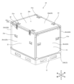
- FIG. 1 is a perspective view showing a heat insulating box according to a first embodiment of the present disclosure.
- FIG. 2 is an exploded perspective view of the insulating box.
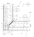
- FIG. 3 is a cross-sectional view of a portion of the insulating box.
- FIG. 4 is an exploded perspective view of the vacuum insulation panel.
- 5A, 5B, and 5C show the encapsulant used in the compression set test in a compressed state by a compression plate and after being released from the compressed state.
- Fig. 6A shows a core formed of four core portions
- Fig. 6B shows a core formed of six core portions
- Fig. 6C shows a base material of the core portions used in the cores of Fig. 6A and 6B
- FIG. 6D shows a base material of the core portions used in the core of Fig. 6B.
- FIG. 7 is a cross-sectional view showing a part of a vacuum insulation panel according to the second modification.
- FIG. 8 is an exploded perspective view showing an insulating box according to the second embodiment of the present disclosure.
- FIG. 9 is a cross-sectional view of the insulating box.
- FIG. 10 is a view of the thermal storage panel as viewed from the inside in the thickness direction.
- FIG. 11 is an exploded perspective view of the thermal storage panel.
- 12A and 12B are cross-sectional views of a thermal storage panel and a portion of the thermal storage panel, respectively.
- FIG. 13 is a cross-sectional view of a thermal storage panel according to a modified example.
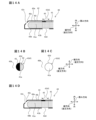
- FIG. 14A is a cross-sectional view of a portion of a heat storage panel in which a determination mark is provided on a filling bag.
- Fig. 14B is a view of the determination mark from a second through-hole through unfrozen heat storage material.
- Fig. 14C is a view of the second through-hole through frozen heat storage material.
- Fig. 14D is a cross-sectional view of a portion of a heat storage panel in which a determination mark is provided on a storage container.
- the insulation box 10 is an insulated container that contains items such as medicines, specimens, and food in its insulation space 10a and is used for transporting and storing them.
- the insulation box 10 is not limited to this and may be, for example, a portable insulation box.
- the insulation box 10 is attached to a pallet 11, but the insulation box 10 does not have to be attached to the pallet 11.
- the insulating box 10 is, for example, rectangular and includes a plurality of (for example, six) insulating plates 20 and an insulating space 10a, which is an internal space surrounded by these insulating plates 20.
- the insulating plates 20 are rectangular flat plates.
- the insulating plates 20 include an upper insulating plate 20a, a lower insulating plate 20b ( Figure 2) and four side wall insulating plates 20c1 to 20c4.
- the side wall insulating plates 20c1 to 20c4 include a front insulating plate 20c1, a rear insulating plate 20c2, a left insulating plate 20c3 and a right insulating plate 20c4, and form a rectangular cylindrical side wall with an upper opening and a lower opening.
- the lower insulating plate 20b forms the bottom of the insulating box 10, which covers the lower opening of this side wall.
- the upper insulating plate 20a forms a lid of the insulating box 10, which covers the upper opening of the side wall in an openable and closable manner.
- the insulation board 20 has a vacuum insulation panel 30 and a protective plate 21 that protects the vacuum insulation panel 30.
- the side of the protective plate 21 facing the vacuum insulation panel 30 is referred to as the inside, and the opposite side is referred to as the outside.
- the outer surface of the protective plate 21 forms the outer surface of the insulation board 20, and a first inner surface 30a, which is the inner surface of the vacuum insulation panel 30, forms the inner surface of the insulation board 20.
- the first inner surfaces 30a of the vacuum insulation panels 30 of the six insulation boards 20 surround the periphery of the insulation space 10a of the insulation box 10. As a result, the first inner surface 30a forms the insulation space 10a.
- the outer surface of the lower insulation plate 20b and the mounting frame 12 are attached to the upper surface of the rectangular flat pallet 11.
- the mounting frame 12 has a rectangular flat lower frame 12a and a rectangular flat outer frame 12b connected in an L-shape.
- the lower frame 12a is attached to the upper surface of the pallet 11 so that its inner edge is aligned with the outer periphery of the lower insulation plate 20b.
- the outer frame 12b rises from the outer edge of the lower frame 12a.
- the lower ends of the side wall insulation plates 20c1 to 20c4 are inserted between the lower insulation plate 20b and the outer frame 12b, so that the side wall insulation plates 20c1 to 20c4 are combined with the lower insulation plate 20b and rise upward from the lower frame 12a.
- the outer surface of the protective plate 21 of the sidewall insulation plates 20c1 to 20c4 is provided with handles 21a, which are, for example, two recesses.
- the outer surface of the protective plate 21 of the upper insulation plate 20a which is disposed on top of these sidewall insulation plates 20c1 to 20c4, is provided with, for example, four handles 21a. This allows the user to easily transport and assemble the insulation plate 20 by using the handles 21a, even if the insulation box 10 is a container and the insulation plate 20 is large.
- two engagement portions 22a of the locks 22 are attached to the outer surfaces of the protective plates 21 of the front insulating plate 20c1 and the rear insulating plate 20c2.
- two engagement portions 22b of the locks 22 are attached to the front and rear ends of the protective plate 21 of the upper insulating plate 20a.
- the engagement portion 22a of the front insulating plate 20c1 engages with the engagement portion 22b at the front end of the upper insulating plate 20a
- the engagement portion 22a of the rear insulating plate 20c2 engages with the engagement portion 22b at the rear end of the upper insulating plate 20a, thereby fixing the upper insulating plate 20a to the front insulating plate 20c1 and the rear insulating plate 20c2.
- the insulation board 20 has a heat insulator 23 and a protective frame 24 in addition to the vacuum insulation panel 30 and the protective plate 21.
- the heat insulator 23 is a rectangular flat plate and is made of a foam material such as polyethylene foam.
- the heat insulator 23 is disposed between the vacuum insulation panel 30 and the protective plate 21 in the thickness direction perpendicular to the first inner surface 30a of the vacuum insulation panel 30. In the orthogonal direction perpendicular to the thickness direction, the size of the heat insulator 23 is larger than that of the vacuum insulation panel 30, and the size of the protective plate 21 is larger than that of the heat insulator 23.
- the inner surface of the heat insulator 23 covers the entire first outer surface 30b, which is the outer surface of the vacuum insulation panel 30, and the inner surface of the protective plate 21 covers the entire outer surface of the heat insulator 23.
- the vacuum insulation panel 30 is protected from external forces by the heat insulator 23 and the protective plate 21.
- the vacuum insulation panel 30 has a first chamfered surface 30d connected to the outer peripheral edge of the first outer surface 30b, and a first flange 31 protruding perpendicularly from the outer peripheral edge of the first outer surface 30b.
- the first flange 31 is overlapped on the insulation body 23 along the thickness direction and covered by the protective frame 24.
- This protective frame 24 is fixed to the inner surface of the protective plate 21, thereby attaching the vacuum insulation panel 30 and the insulation body 23 to the protective plate 21.
- the protective frame 24 surrounds the periphery of the side surface of the insulation body 23 and the periphery of the first chamfered surface 30d, protecting the side surface of the insulation body 23 and the first chamfered surface 30d of the vacuum insulation panel 30.
- the vacuum insulation panel 30 has an outer covering material 32 having an internal space, and a core material 33 housed in the internal space of the outer covering material 32.
- the outer covering material 32 is a molded body made of a material having gas barrier properties, and its internal space is depressurized to a predetermined pressure lower than atmospheric pressure and sealed.
- the outer covering material 32 may have a thickness of, for example, 1.0 mm, and may have a laminated structure made of a heat-weldable thermoplastic resin layer, an air barrier layer such as an ethylene-vinyl alcohol copolymer or a polyvinyl alcohol polymer, and a water vapor barrier layer such as polypropylene.
- the outer covering material 32 has, for example, a first inner wall 32a and a first outer wall 32b.
- the first inner wall 32a has a truncated pyramid shape such as a quadrangular pyramid shape, and has a rectangular opening, a first inner wall flange portion 32a1 surrounding the periphery of the opening, and a first inner wall recessed portion 32a2 recessed inward in the thickness direction from the first inner wall flange portion 32a1.
- the first outer wall 32b has a rectangular flat plate shape, and has a first covering portion 32b1 covering the opening of the first inner wall 32a, and a first outer wall flange portion 32b2 surrounding the periphery of the first covering portion 32b1.
- This first outer wall flange portion 32b2 has the same shape and size as the first inner wall flange portion 32a1.
- the first inner wall 32a is formed, for example, by vacuum molding, so that the outer covering material 32 can be manufactured at low cost without using expensive molding dies such as blow molding and injection molding.
- the core material 33 is inserted into the first inner wall recess 32a2 through the opening of the first inner wall 32a, and the opening of the first inner wall 32a is covered by the first covering portion 32b1 of the first outer wall 32b, thereby containing the core material 33 in the internal space of the outer covering material 32. Then, the first inner wall flange portion 32a1 and the first outer wall flange portion 32b2 are overlapped and heat-welded.
- the first flange 31 is formed by the heat-welded first inner wall flange portion 32a1 and first outer wall flange portion 32b2.
- first inner surface 30a, the first inclined surface 30c, and the first chamfered surface 30d of the vacuum insulation panel 30 are formed by the surface of the first inner wall recess 32a2 of the first inner wall 32a that is opposite to the surface facing the first outer wall 32b in the thickness direction.
- first outer surface 30b of the vacuum insulation panel 30 is formed by the surface of the first covering portion 32b1 of the first outer wall 32b opposite the surface facing the first inner wall 32a in the thickness direction. Then, air is sucked from the internal space of the outer covering material 32 through a suction port provided in the first inner wall 32a or the first outer wall 32b, and the internal space of the outer covering material 32 is depressurized. Then, the suction port is sealed with a sealing member, thereby sealing the internal space of the outer covering material 32.
- the core material 33 is made of a porous material with low thermal conductivity, and serves as the skeleton of the vacuum insulation panel 30, forming the internal space of the exterior material 32.
- the core material 33 has a first core material layer 33a made of glass wool, and a second core material layer 33b made of an open-cell foam such as polyurethane foam with an open-cell structure.
- the second core material layer 33b has a truncated pyramid shape, such as a quadrangular pyramid shape, and has an inner surface and a core material depression 33b1 recessed from the inner surface.
- the first core material layer 33a has a rectangular flat plate shape, and is received in the core material depression 33b1 of the second core material layer 33b, forming a truncated pyramid shape, such as a quadrangular pyramid shape, of the core material 33.
- the core material 33 is composed of two core material layers 33a, 33b stacked in the thickness direction, but it may be composed of one core material 33, or may be composed of three or more core material layers stacked in the thickness direction.
- the core material 33 is not limited to glass wool and polyurethane foam with an open-cell structure, but may be composed of a porous material such as an aggregate of glass fibers and an aggregate of inorganic fine particles.
- a gas adsorbent 34 may be contained in the internal space of the outer covering material 32 of the vacuum insulation panel 30.
- the vacuum insulation panel 30 is recessed from the inner surface of the core material 33 to the outside in the thickness direction, and the gas adsorbent 34 is disposed in this recess and covered by the outer covering material 32.
- the gas adsorbent 34 adsorbs gases such as water vapor and air that remain in or penetrate into the internal space of the outer covering material 32. This makes it possible to maintain a low pressure in the internal space of the outer covering material 32.
- a pressure sensor 35 may be housed in the internal space of the outer covering material 32 of the vacuum insulation panel 30.
- the pressure sensor 35 has a pressure detection unit 35a, a transmission unit 35b, a power supply unit 35c, and a sensor case 35d that houses these.
- the outer covering material 32 is made of a non-metallic material, such as synthetic resin, that is permeable to radio waves for wireless communication. This makes it possible for the pressure detected by the pressure sensor 35 to be wirelessly communicated with the outside of the outer covering material 32.
- the pressure detector 35a includes, for example, a heater and a thermocouple, and measures the air pressure (vacuum level) in the internal space of the outer covering material 32 by measuring the surrounding thermal conductivity characteristics from the temperature detected by the thermocouple when the heater is heated.
- the configuration of the pressure detector 35a is not limited to this, and for example, a microelectromechanical system (MEMS) such as a piezoelectric type, a capacitance type, or a vibration type may be used.
- MEMS microelectromechanical system
- the transmitter 35b is electrically connected to the pressure detector 35a, and transmits information related to the pressure detected by the pressure detector 35a to the outside of the outer covering material 32 via wireless communication.
- the transmitter 35b has a communication control IC, a memory, an antenna, and the like.
- the transmitter 35b is a short-range wireless communication device that uses a frequency in the 13.56 MHz band, and transmits information via NFC (Near Field Communication).
- the power supply unit 35c is electrically connected to the voltage detection unit 35a and the transmission unit 35b and supplies power to them.
- the power supply unit 35c has a power supply control IC and a power receiving unit for wireless power supply using the magnetic resonance method.
- This power receiving unit includes a secondary coil (power receiving coil) that receives power contactlessly from a primary coil (power transmitting coil) outside the outer sheath material 32.
- the power receiving coil receives power transmitted from the power transmitting coil, and the power supply control IC supplies this power to the voltage detection unit 35a and the transmission unit 35b.
- the sensor case 35d is formed from a non-metallic material such as resin, and has, for example, a flat plate shape in the thickness direction, with multiple through holes connecting the inside and outside.
- a pressure sensor 35 is provided in each vacuum insulation panel 30 of the insulation box 10. In the internal space of the outer covering material 32 of this vacuum insulation panel 30, it is recessed from the inner surface of the core material 33 to the outside in the thickness direction, and the pressure sensor 35 is disposed in this recess and covered by the outer covering material 32. As a result, the pressure sensor 35 is disposed closer to the first inner surface 30a than the first outer surface 30b in the thickness direction.
- the insulation performance of such a vacuum insulation panel 30 is inspected using a tester 13.
- the tester 13 has a receiving unit 13a and a power transmitting unit 13b, and is connected to a computer 13d.
- the receiving unit 13a is equipped with, for example, a communication control IC, a memory, an antenna, etc., and is capable of communicating with the transmitting unit 35b of the pressure sensor 35 of the vacuum insulation panel 30, for example, via NFC.
- the power transmitting unit 13b includes a power transmitting coil forming a primary coil, and generates a magnetic field when power is supplied from a power source.
- the user When testing the thermal insulation performance of the vacuum insulation panel 30 using this tester 13, the user brings the tester 13 into contact with the first inner surface 30a of the vacuum insulation panel 30 so as to face the pressure sensor 35 through the outer covering material 32 of the vacuum insulation panel 30.
- the power transmission unit 13b of the tester 13 When the user supplies power to the power transmission unit 13b of the tester 13, the power transmission unit 13b generates a magnetic field, which generates electromagnetic induction in the secondary coil (receiving coil) of the power supply unit 35c of the vacuum insulation panel 30, and powers the pressure sensor 35.
- the pressure sensor 35 detects pressure with the pressure detection unit 35a and transmits information related to the detected pressure from the transmission unit 35b.
- the transmitted information is received by the receiving unit 13a of the tester 13 and sent to the computer 13d. Based on the input information, the computer 13d determines whether the thermal insulation performance of the vacuum insulation panel 30 is acceptable and outputs (e.g., displays) the result. In this way, the user can inspect the insulating performance of the vacuum insulation panel 30.
- the protective plate 21 facing the pressure sensor 35 may be made of a material that transmits radio waves for wireless communication, such as resin.
- the user contacts the tester 13 with the outer surface of the resin part of the protective plate 21. This allows the tester 13 to face the pressure sensor 35 via the resin part of the protective plate 21 and the outer covering material 32 of the vacuum insulation panel 30, and to wirelessly communicate with the pressure sensor 35. Therefore, the tester 13 can also inspect the insulation performance of the vacuum insulation panel 30 by receiving the pressure detected by the pressure sensor 35.
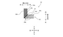
- the vacuum insulation panel 30 has a truncated pyramid shape such as a quadrangular pyramid shape, and has a first inner surface 30a, a first outer surface 30b, a first inclined surface 30c, and a first chamfered surface 30d.
- the first inner surface 30a and the first outer surface 30b are rectangular and perpendicular to the thickness direction.
- the first inner surface 30a of the vacuum insulation panel 30 is formed by the first inner wall 32a of the outer covering material 32, and forms the inner surface of the insulation plate 20.
- the first outer surface 30b of the vacuum insulation panel 30 is formed by the first covering portion 32b1 (FIG.
- a first flange 31 extends from the outer peripheral edge of the first outer surface 30b so as to surround the periphery of the first outer surface 30b of the vacuum insulation panel 30.
- the first chamfered surface 30d has its outer end connected to the outer peripheral edge of the first outer surface 30b and extends inward in the thickness direction from the outer peripheral edge of the first outer surface 30b.
- the first inclined surface 30c has its outer end connected to the inner end of the first chamfered surface 30d and its inner end connected to the outer peripheral edge of the first inner surface 30a.
- the first inclined surface 30c is inclined in the thickness direction and the perpendicular direction, and the inclination angle ⁇ in the thickness direction is 45 degrees. Due to this first inclined surface 30c, the cross-sectional area of the vacuum insulation panel 30 perpendicular to the thickness direction becomes larger in the thickness direction from the first inner surface 30a to the first outer surface 30b, that is, toward the outside in the thickness direction.
- the first inclined surfaces 30c of adjacent vacuum insulation panels 30 face each other.
- the vacuum insulation panel 30 of the lower insulation plate 20b and the vacuum insulation panel 30 of the left insulation plate 20c3 are adjacent to each other, and the first inclined surface 30c of the lower insulation plate 20b faces the first inclined surface 30c of the left insulation plate 20c3.
- These opposing first inclined surfaces 30c are arranged parallel to each other.
- the vacuum insulation panel 30 of the lower insulation plate 20b shown in FIG. 2 is adjacent to the vacuum insulation panels 30 of the front insulation plate 20c1, the rear insulation plate 20c2, and the right insulation plate 20c4, and the first inclined surface 30c of the vacuum insulation panel 30 of the lower insulation plate 20b faces the first inclined surface 30c of the vacuum insulation panel 30 of the insulation plates 20c1, 20c2, and 20c4.
- the vacuum insulation panel 30 of the upper insulation plate 20a is adjacent to the sidewall insulation plates 20c1 to 20c4, and the first inclined surface 30c of the vacuum insulation panel 30 of the upper insulation plate 20a faces the first inclined surface 30c of the sidewall insulation plates 20c1 to 20c4.
- the vacuum insulation panel 30 of the front insulation plate 20c1 is adjacent to the vacuum insulation panels 30 of the left insulation plate 20c3 and the right insulation plate 20c4, and the first inclined surface 30c of the vacuum insulation panel 30 of the front insulation plate 20c1 faces the first inclined surface 30c of the vacuum insulation panel 30 of the insulation plates 20c3 and 20c4.
- the vacuum insulation panel 30 of the rear insulation plate 20c2 is adjacent to the vacuum insulation panels 30 of the left insulation plate 20c3 and the right insulation plate 20c4, and the first inclined surface 30c of the vacuum insulation panel 30 of the rear insulation plate 20c2 faces the first inclined surface 30c of the vacuum insulation panel 30 of the insulation plates 20c3 and 20c4.
- the first inclined surface 30c is inclined with respect to the first inner surface 30a and the first chamfered surface 30d, so that the angle between the first inner surface 30a and the first inclined surface 30c, and the angle between the first inclined surface 30c and the first chamfered surface 30d, are greater than 90 degrees. Therefore, when assembling the vacuum insulation panels 30 with the first inclined surfaces 30c facing each other, even if the corner of one vacuum insulation panel 30 hits the other vacuum insulation panel 30, damage to the vacuum insulation panel 30 can be suppressed. Therefore, the assembly work of the insulation box 10 using the vacuum insulation panels 30 can be easily carried out.
- the gap between the first inclined surface 30c of the lower insulation board 20b and the outer frame 12b becomes larger the higher up. Therefore, even if the sidewall insulation boards 20c1-20c4 are inclined, the lower ends of the sidewall insulation boards 20c1-20c4 can be easily inserted into this gap without hitting the lower insulation board 20b. This makes it easy to assemble the insulation box 10 using the vacuum insulation panel 30. Furthermore, in the case of an insulation box 10 that is large in size, such as a container, even if the vacuum insulation panel 30 is prone to tilting significantly, damage to the vacuum insulation panel 30 caused by corners can be suppressed, improving the ease of assembly of the insulation box 10.
- the lower ends of the sidewall insulation plates 20c1-20c4 can be inserted into the gap between the first inclined surface 30c of the lower insulation plate 20b and the outer frame 12b, and the tilt can be adjusted so that the sidewall insulation plates 20c1-20c4 are parallel in the vertical direction. In this way, by adjusting the tilt of the vacuum insulation panel 30 while inserting the lower end of the vacuum insulation panel 30, the workability of assembling the insulation box 10 can be improved.
- the dimension h1 of the first chamfered surface 30d in the thickness direction satisfies the formula for the dimension H1 of the vacuum insulation panel 30 in the thickness direction: h1 ⁇ (1 - ⁇ 2/2) H1.
- This dimension H1 is the dimension between the first inner surface 30a and the first outer surface 30b of the vacuum insulation panel 30 in the thickness direction.
- the dimension L1 between the outer end and the inner end of the first inclined surface 30c is larger than the dimension H1 of the vacuum insulation panel 30. Therefore, between the insulation space 10a surrounded by the vacuum insulation panel 30 and the outside, the dimension L1 of the heat transfer path 14, which is the gap between the opposing first inclined surfaces 30c, is longer than the dimension H1. Therefore, the heat transfer between the insulation space 10a and the outside via the heat transfer path 14 can be reduced, and the temperature change of the insulation space 10a can be reduced.
- the first chamfered surface 30d can prevent the first flanges 31 from contacting each other between adjacent vacuum insulation panels 30. That is, in the example of FIG. 3, the corner between the first outer surface 30b and the first inclined surface 30c of the vacuum insulation panel 30 is chamfered to form a first chamfered surface 30d between the first outer surface 30b and the first inclined surface 30c, and a first chamfered space 30e between the first chamfered surface 30d, the extended surface of the first outer surface 30b, and the extended surface of the first inclined surface 30c. In the lower insulation plate 20b, the first flange 31 protruding to the left from the first outer surface 30b fits into the first chamfered space 30e.
- the first flange 31 protruding downward from the first outer surface 30b fits into the first chamfered space 30e.
- This allows the dimension W of the heat transfer path 14 between the opposing first inclined surfaces 30c to be kept small, reducing heat transfer through the heat transfer path 14 and reducing temperature changes in the insulating space 10a.
- the insulation box 10 further includes a sealant 25 disposed between the first inclined surfaces 30c.
- the sealant 25 is, for example, made of a porous material, has a thin sheet shape, and is attached to the first inclined surfaces 30c with an adhesive or the like.
- a gap is provided between the first inclined surfaces 30c due to a dimensional error of the vacuum insulation panel 30 or an assembly error of the insulation plate 20. Even in such a case, the sealant 25 is interposed between the first inclined surfaces 30c, thereby reducing the flow of air in the heat transfer path 14, which is the gap. This suppresses heat transfer to the insulation space 10a due to the flow of air, and reduces the temperature change of the insulation space 10a.
- the compression set of the sealing material 25 is 60% or less.
- the compression set is measured, for example, by the following compression set test using the sealing material 25 of FIG. 5A.
- the sealing material 25 has a thickness d1 of 10 mm and a size of 50 mm square in the orthogonal direction.
- FIG. 5B the sealing material 25 is sandwiched and compressed between two aluminum compression plates B at 5° C. so that the thickness d2 is 1 mm.
- the sealing material 25 is left in a thermostatic chamber maintained at an ambient temperature of 5° C. for 2 hours, 5 hours, 22 hours, 72 hours, and 220 hours.
- FIG. 5C the sealing material 25 is taken out from between the two compression plates B at 5° C., and after being released from the compressed state and left for 24 hours, the thickness d3 of the sealing material 25 is measured.
- the insulating box 10 is stored in a warehouse at 5°C, and opening and closing of the insulating box 10 is also performed in a warehouse at 5°C, so the compressive strain test of the sealing material 25 was performed at 5°C.
- the temperature for the compressive strain test of the sealing material 25 is not limited to this, and is determined according to the temperature range in which the sealing material 25 is used. For example, if the insulating box 10 is opened and closed at 20°C, the compressive strain test of the sealing material 25 may be performed at 20°C.
- the compression set of the sealing material 25 after such a compression strain test is calculated by the following formula.
- d1 is the thickness of the sealing material 25 before compression as shown in Fig. 5A
- d2 is the thickness of the sealing material 25 in a compressed state before a constant temperature test as shown in Fig. 5B
- d3 is the thickness of the sealing material 25 after being released from the compressed state after a constant temperature test and left for 30 minutes as shown in Fig. 5C.
- the thickness d1 is 10 mm and the thickness d2 is 1 mm, so the compression set of the sealing material 25 is calculated from the measured thickness d3.
- Compression set (%) (d1 - d3) / (d1 - d2) x 100
- the sealant 25 can seal the gap between the first inclined surfaces 30c of the vacuum insulation panel 30. That is, for example, the design accuracy due to dimensional errors of the vacuum insulation panel 30 is ⁇ 1 mm from the design center value. Also, the assembly accuracy due to assembly errors of the insulation plate 20 is ⁇ 1 mm from the design center value. In this case, the design value of the gap between the first inclined surfaces 30c of the vacuum insulation panel 30 is 3 mm ⁇ 2 mm. As a result, the maximum gap value is 5 mm and the minimum gap value is 1 mm.
- the thickness d2 of the sealing material 25 placed in this gap when it is in the most compressed state is 1 mm. Since the compression set of this sealing material 25 is 60% or less, the thickness d3 of the sealing material 25 after compression is released is restored to a thickness of 5.4 mm or more. Since this thickness is greater than the maximum value of the gap, even if the first inclined surfaces 30c are next assembled with the gap between them at the maximum value of 5 mm, the sealing material 25 placed in this gap can seal the gap. This reduces heat transfer to the insulated space 10a due to the flow of air through the heat transfer path 14, which is the gap, and reduces temperature changes in the insulated space 10a.
- the thickness d1 of the sealing material 25 is 10 mm or more because the compression rate of the sealing material 25 is 50% or more to ensure airtightness.
- the compression set of such a sealing material 25 is 60% or less, and more preferably 55.6% or less. Therefore, even in a gap of 1 mm or more and 5 mm or less, the compression rate of the sealing material 25 is 50% or more, so the compressed sealing material 25 can ensure airtightness in the gap and seal the gap. This reduces heat transfer to the insulating space 10a due to the flow of air in the heat transfer path 14, which is the gap, and reduces temperature changes in the insulating space 10a.
- the maximum gap between the first inclined surfaces 30c is 5 mm, so the thickness of the sealing material 25 is set to 10 mm or more, but the thickness of the sealing material 25 is not limited to this.
- a sealing material 25 having a thickness of 10 mm or more may be placed on only one of the opposing first inclined surfaces 30c.
- a sealing material 25 having a thickness of 5 mm or more may be placed on both of the opposing first inclined surfaces 30c. In this case, two sheets of sealing material 25 are placed in the gap between the opposing first inclined surfaces 30c, and the total thickness of the sealing material 25 may be 10 mm or more.
- the compression set of the sealing material 25 is small at 60% or less, the recovery rate of the sealing material 25 is high.
- the dimension W of the gap between the opposing first inclined surfaces 30c changes each time the insulation box 10 is assembled. Even in cases in which there is variation in the dimension W of the gap, the sealing material 25 recovers each time the insulation box 10 is disassembled, so even gaps of maximum size can be sealed.
- the sealing material 25 has a compressive strength of 3 N/ cm2 or less when compressed by 50%.
- the upper insulating plate 20a is fixed to each of the front insulating plate 20c1 and the rear insulating plate 20c2 by locks 22.
- the compressive strength P of the sealing material 25 when compressed by 50% is expressed by the following formula, where F is the tensile load of the locks 22, n is the number of locks 22, X is the weight of the upper insulating plate 20a, and A is the contact area between the upper insulating plate 20a and the sealing material 25.
- F the tensile load of the locks 22
- n is the number of locks
- X is the weight of the upper insulating plate 20a
- A is the contact area between the upper insulating plate 20a and the sealing material 25.
- the sealing material 25 is made of foamed rubber, and more preferably, foamed ethylene propylene rubber.
- the foamed ethylene propylene rubber sealing material 25 has a compression set of 60% or less, and a compression strength of 3 N/cm2 or less when compressed by 50%. This allows the sealing material 25 to have a high recovery rate, and is compressed by 50% or more in the gaps between the first inclined surfaces 30c. Therefore, even if there is variation in the dimensions of the gaps, the sealing material 25 can seal the gaps to reduce heat transfer to the insulation space 10a due to the flow of air through the heat transfer path 14, which is the gap, and reduce the temperature change of the insulation space 10a.
- the core material 33 of the vacuum insulation panel 30 may be formed of a plurality of core material portions 33c arranged in an orthogonal direction.
- two core material portions 33c are arranged along one of the orthogonal directions (horizontal direction), and two core material portions 33c are arranged along the vertical direction perpendicular to the horizontal direction.
- three core material portions 33c are arranged along the horizontal direction of the orthogonal direction, and two core material portions 33c are arranged along the vertical direction of the orthogonal direction. The larger the size of the core material portions 33c and the core material 33, the larger the warpage of these.
- the warpage of the core material 33 formed by a plurality of small core material portions 33c is smaller than the warpage of one large core material 33, so that the warpage of the core material 33 can be reduced by forming it by a plurality of core material portions 33c.
- the core portion 33c in the example of Fig. 6A is formed, for example, by cutting one of a pair of sides extending in the horizontal direction and one of a pair of sides extending in the vertical direction in the base material 33d of one truncated pyramidal core portion 33c shown in Fig. 6C. Then, two core portions 33c are arranged in the horizontal and vertical directions so that the cut surfaces of the core portions 33c face each other, thereby forming the truncated pyramidal core portion 33.
- the central core portion 33c2 is formed by cutting one of a pair of sides extending horizontally and both of a pair of sides extending vertically in a single truncated pyramidal substrate 33d shown in Figure 6D. Furthermore, of the three core portions 33c, the two core portions 33c1 sandwiching the core portion 33c2 between them can be formed by cutting the substrate 33d as shown in Figure 6C, similar to the core portion 33c in Figure 6A.
- the size of one core portion 33c is formed to be smaller than the other core portion 33c.
- core portions 33c1, 33c2 are arranged horizontally and two core portions 33c1, 33c2 are arranged vertically so that the cut surfaces of the core portions 33c1, 33c2 face each other, forming a truncated pyramid-shaped core portion 33.
- the core material portions 33c By adjusting the number and size of the core material portions 33c, it is possible to form core materials 33 of multiple shapes and sizes.
- the size of the mold for the base material 33d is smaller than the size of the mold for the core material 33, and the mold costs can be reduced.
- the number of molds for the base material 33d is smaller than if a mold were formed for each core material portion 33c, and the mold costs can be reduced. In this way, the core material 33 can be manufactured cheaply.
- This core portion 33c is made of polyurethane foam with an open-cell structure.
- Polyurethane foam with an open-cell structure contains multiple air bubbles that are interconnected. The interconnection of these multiple air bubbles allows air to be exhausted from the air bubbles of the core portion 33c contained within the exterior material 32. This increases the degree of vacuum within the exterior material 32, and improves the insulating properties of the vacuum insulation panel 30.
- open-cell polyurethane foam is a synthetic resin foam that is porous due to the inclusion of air bubbles and is formed as a single unit, it is easier to cut than an aggregate of glass fiber, silica powder, etc. Therefore, by cutting the base material 33d made of open-cell polyurethane foam, the core portion 33c can be easily formed.
- one core material 33 housed in the outer covering material 32 is formed from multiple core material portions 33c.
- the core material 33 may have a first core material layer 33a and a second core material layer 33b stacked in the thickness direction.
- at least one of the first core material layer 33a and the second core material layer 33b may be formed from multiple core material portions 33c arranged in an orthogonal direction.
- the vacuum insulation panel 30 may not have the first chamfered surface 30d (FIG. 3).
- the vacuum insulation panel 30 has a first inner surface 30a, a first outer surface 30b, and a first inclined surface 30c.
- the outer end of the first inclined surface 30c is connected to the outer peripheral edge of the first outer surface 30b, and the inner end of the first inclined surface 30c is connected to the outer peripheral edge of the first inner surface 30a.
- the first inclined surface 30c is inclined with respect to the thickness direction and the perpendicular direction, and the inclination angle ⁇ with respect to the thickness direction is 45 degrees.
- the outer covering material 32 of the vacuum insulation panel 30 is formed, for example, by blow molding, and is not provided with a first flange 31. Therefore, even if the first chamfered surface 30d is not provided on the vacuum insulation panel 30, the first flanges 31 do not collide with each other in adjacent vacuum insulation panels 30, and the first inclined surfaces 30c can face each other.
- This vacuum insulation panel 30 has a longer heat transfer path 14 between the first inclined surfaces 30c than a vacuum insulation panel 30 provided with the first chamfered surface 30d, so that heat transfer via the heat transfer path 14 can be further reduced, and temperature changes in the insulation space 10a can be reduced.
- the heat insulation box 10 includes a plurality of (e.g., 10) heat storage panels 40 arranged in the heat insulation space 10a and used as a cold insulation material or a heat insulation material, and a heat transfer body 50 arranged on the bottom surface 10b of the heat insulation box 10.
- a plurality of (e.g., 10) heat storage panels 40 arranged in the heat insulation space 10a and used as a cold insulation material or a heat insulation material, and a heat transfer body 50 arranged on the bottom surface 10b of the heat insulation box 10.
- the heat storage panel 40 will be described as being used as a cold insulation material that maintains the temperature of the heat insulation space 10a at a temperature lower than a predetermined temperature such as the outside air temperature and room temperature (e.g., 23 degrees) of the heat insulation box 10, but it may also be used as a heat insulation material that maintains the temperature of the heat insulation space 10a at a temperature higher than the predetermined temperature.
- the heat storage panel 40 is frozen in a freezer to, for example, 5 degrees below the management temperature according to the management temperature of the goods such as medicines to be stored in the heat insulation box 10, and then arranged in the heat insulation space 10a.
- the heat storage panel 40 is smaller than the vacuum insulation panel 30 of the insulation plate 20 forming the insulation box 10, and is arranged inside the vacuum insulation panel 30 in the thickness direction.
- the heat storage panel 40 has a second outer surface 40b which is an outer surface facing the first inner surface 30a of the vacuum insulation panel 30 of the insulation plate 20a in the insulation box 10.
- the multiple heat storage panels 40 include, for example, two upper heat storage panels 40, two front heat storage panels 40, two rear heat storage panels 40, two left heat storage panels 40, and two right heat storage panels 40.
- the two upper heat storage panels 40 are arranged at intervals in the left-right direction, and the second outer surface 40b of the upper heat storage panel 40 faces and contacts the first inner surface 30a of the vacuum insulation panel 30 of the upper insulation plate 20a.
- the two front heat storage panels 40 are arranged at intervals in the left-right direction, and the second outer surface 40b of the front heat storage panel 40 faces and contacts the first inner surface 30a of the vacuum insulation panel 30 of the front insulation plate 20c1.
- the two rear heat storage panels 40 are arranged at intervals in the left-right direction, and the second outer surface 40b of the rear heat storage panel 40 faces and contacts the first inner surface 30a of the vacuum insulation panel 30 of the rear insulation plate 20c2.
- the two left heat storage panels 40 are arranged at intervals in the front-rear direction, and the second outer surface 40b of the left heat storage panel 40 faces and contacts the first inner surface 30a of the vacuum insulation panel 30 of the left insulation plate 20c3.
- the two right-side heat storage panels 40 are arranged with a gap between them in the front-to-rear direction, and the second outer surface 40b of the right-side heat storage panel 40 faces and contacts the first inner surface 30a of the vacuum insulation panel 30 of the right-side insulation plate 20c4.
- the heat transfer body 50 is made of a material having a high thermal conductivity, such as a metal such as aluminum, or a resin. Among these, the heat transfer body 50 made of aluminum can reduce the weight of the heat transfer body 50 and provide good thermal conductivity.
- the aluminum may contain other metals, that is, the aluminum may also contain alloys thereof.
- the heat transfer body 50 has a frame body 51, a support portion 52, and a mounting plate 53.
- the frame body 51 is disposed on the first inner surface 30a of the lower insulating plate 20b that forms the bottom surface 10b of the insulating box 10.
- the mounting plate 53 is a rectangular flat plate and is disposed on the frame body 51.
- the frame 51 has a plurality of (two in the example of FIG. 8) first extension portions 51a that are rectangular columns extending in the left-right direction, and a plurality of (six in the example of FIG. 8) second extension portions 51b that are rectangular columns extending in the front-rear direction.
- the two first extension portions 51a are arranged at intervals in the front-rear direction.
- the six second extension portions 51b are arranged at intervals in the left-right direction between the two first extension portions 51a.
- the ends of the second extension portions 51b are connected to the first extension portion 51a.
- the frame 51 has a space 51c surrounded by the first extension portions 51a and the second extension portions 51b, which reduces the weight and cost of the heat transfer body 50.
- a number of support parts 52 are attached to the outer periphery of the frame body 51.
- the support parts 52 are flat, and two support parts 52 form a pair.
- four pairs of support parts 52 are attached to the outer periphery of the first extension part 51a with a gap between them along the first extension part 51a.
- four pairs of support parts 52 are attached to the outer periphery of the second extension part 51b with a gap between them along the second extension part 51b located at the end of the six second extension parts 51b.
- the support portion 52 is, for example, in the shape of a right-angled triangle, and the dimension protruding from the frame body 51 increases toward the bottom.
- One adjacent side of the support portion 52 extends in the vertical direction and is attached to the outer periphery of the frame body 51, and the other adjacent side extends in the horizontal or front-to-back direction and faces the bottom surface 10b of the insulation box 10.
- the oblique side 52a of the support portion 52 is inclined at 45 degrees to the adjacent side, and is inclined inward in the thickness direction toward the top.
- the oblique side 52a of the support portion 52 faces the first inner surface 30a of the side wall insulation boards 20c1 to 20c4 that form the side surface 10c of the insulation box 10, and the distance from this side surface 10c increases toward the top.
- the lower ends of the front heat storage panel 40, rear heat storage panel 40, left heat storage panel 40, and right heat storage panel 40, whose second outer surfaces 40b face the side surface 10c of the insulation box 10, are inserted into this gap. This makes it easy to attach these heat storage panels 40 to the insulation box 10.
- the heat transfer body 50 is sandwiched between the front and rear heat storage panels 40 in the front-to-rear direction, and between the left and right heat storage panels 40 in the left-to-right direction.
- the two first extensions 51a extend in the left-to-right direction, which is the thickness direction of the left and right heat storage panels 40, and are arranged at intervals in the front-to-rear direction, which is the perpendicular direction.
- the six second extensions 51b extend in the front-to-rear direction, which is the thickness direction of the front and rear heat storage panels 40, and are arranged at intervals in the left-to-right direction, which is the perpendicular direction.
- These heat storage panels 40 have a second outer surface 40b facing the side surface 10c of the insulation box 10, and a second inclined surface 40c inclined relative to the second outer surface 40b.
- the second inclined surface 40c of the heat storage panel 40 faces and contacts the oblique side 52a of the support portion 52 of the heat transfer body 50.
- the heat storage panel 40 is supported by the support portion 52 and pressed against the side surface 10c of the insulation box 10, and is therefore stably fixed to the heat transfer body 50 and the insulation box 10.
- the heat transfer body 50 is also cooled by thermal conduction from the heat transfer body 50 to the heat storage panel 40.
- the insulated space 10a in which the heat storage panel 40 and the heat transfer body 50 are arranged is cooled by the heat storage panel 40 and the heat transfer body 50.
- convection occurs in the space 51c surrounded by the first extension portion 51a and the second extension portion 51b in the frame body 51 cooled by the heat storage panel 40. Therefore, the mounting plate 53 covering the space 51c of the frame body 51 is uniformly cooled by the convection in the space 51c and the thermal conduction of the frame body 51.
- the workability of storing the items in the insulating box 10 is improved. That is, for example, if the heat storage panel 40 is frozen to -25°C by a freezer and then further temperature-controlled in a temperature-controlled warehouse at 5°C, it takes a long time, for example 48 hours, for the heat storage panel 40 to reach 5°C by freezing and temperature control. Also, if the heat storage panel 40 is left standing for a long time in a warehouse at 5°C, whereby freezing and temperature control are performed simultaneously, it takes an even longer time, for example 120 hours, for the heat storage panel 40 to reach 5°C by leaving it standing (freezing and temperature control). In contrast, the heat transfer body 50 is cooled by the heat storage panel 40.
- the items may be placed on the placement plate 53 of the heat transfer body 50 after the heat storage panel 40 has been frozen and temperature-controlled, or the items may be placed on the placement plate 53 while the heat storage panel 40 is being frozen and temperature-controlled. In this way, items can be stored in the insulated box 10 without waiting for the heat storage panel 40 to freeze and adjust its temperature, improving the ease of storing items in the insulated box 10.
- the heat transfer body 50 is disposed on the bottom surface 10b of the insulating box 10, but instead of the heat transfer body 50, a heat storage panel 40 may be disposed on the bottom surface 10b of the insulating box 10.
- the heat storage panel 40 cools the insulating space 10a from below as well, making it possible to make the temperature of the insulating space 10a uniform.
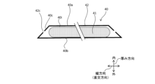
- the heat storage panel 40 has a truncated pyramid shape such as a quadrangular pyramid shape, and has a second inner surface 40a, a second outer surface 40b, a second inclined surface 40c, and a second chamfered surface 40d.
- the second inner surface 40a is the first surface of the heat storage panel 40
- the second outer surface 40b is the second surface of the heat storage panel 40, which is a surface located opposite the first surface with the heat storage pack 41 sandwiched therebetween in the thickness direction perpendicular to the first surface.
- the second inner surface 40a and the second outer surface 40b are rectangular and perpendicular to the thickness direction.
- the area of the second outer surface 40b is larger than the area of the second inner surface 40a.
- the second outer surface 40b is the surface of the heat storage panel 40 opposite the second inner surface 40a in the thickness direction, and faces and contacts the first inner surface 30a of the vacuum insulation panel 30 in the insulation space 10a of the insulation box 10.
- the thickness direction of the heat storage panel 40 is parallel to and in the same direction as the thickness direction of the vacuum insulation panel 30.
- the second chamfered surface 40d has its outer end connected to the outer peripheral edge of the second outer surface 40b, and extends inward in the thickness direction from the outer peripheral edge of the second outer surface 40b.
- the second flange 40e extends in a perpendicular direction from the outer peripheral edge of the second outer surface 40b.
- the second inclined surface 40c has its outer end connected to the inner end of the second chamfered surface 40d, and its inner end connected to the outer peripheral edge of the second inner surface 40a.
- the second inclined surface 40c is inclined with respect to the thickness direction and the perpendicular direction, and the inclination angle ⁇ with respect to the thickness direction (FIG. 12B) is 45 degrees. Due to this second inclined surface 40c, the cross-sectional area of the thermal storage panel 40 perpendicular to the thickness direction increases in the thickness direction from the second inner surface 40a to the second outer surface 40b.
- the second inclined surfaces 40c of adjacent heat storage panels 40 face each other.
- the upper heat storage panel 40 is adjacent to each of the front heat storage panel 40, the rear heat storage panel 40, the left heat storage panel 40, and the right heat storage panel 40, and the second inclined surfaces 40c of these heat storage panels 40 face each other.
- the front heat storage panel 40 is adjacent to each of the left heat storage panel 40 and the right heat storage panel 40, and the second inclined surfaces 40c of these heat storage panels 40 face each other.
- the rear heat storage panel 40 is adjacent to each of the left heat storage panel 40 and the right heat storage panel 40, and the second inclined surface 40c of these heat storage panels 40 faces the second inclined surface 40c of the rear heat storage panel 40.
- These opposing second inclined surfaces 40c are in contact with each other, and these heat storage panels 40 support each other and are fixed to the insulation box 10.
- the heat storage panel 40 has the second inclined surface 40c in this way, the angle between the second inner surface 40a and the second inclined surface 40c, and the angle between the second inclined surface 40c and the second chamfered surface 40d are greater than 90 degrees. Therefore, even if the corner of one heat storage panel 40 hits the other heat storage panel 40 when assembling the heat storage panels 40 together, damage to the heat storage panel 40 can be suppressed.
- the dimension h2 of the second chamfered surface 40d in the thickness direction may satisfy the formula for the dimension H2 of the thermal storage panel 40 in the thickness direction: h2 ⁇ (1- ⁇ 2/2)H2.
- This dimension H2 is the dimension between the second inner surface 40a and the second outer surface 40b of the thermal storage panel 40 in the thickness direction.
- the dimension L2 between the outer end and inner end of the second inclined surface 40c is larger than the dimension H2 of the thermal storage panel 40.
- adjacent thermal storage panels 40 can stably support each other.
- the second chamfered surface 40d can suppress contact between the second flanges 40e of adjacent heat storage panels 40. That is, the corners of the second outer surface 40b and the second inclined surface 40c of the heat storage panel 40 are chamfered to form a second chamfered surface 40d between the second outer surface 40b and the second inclined surface 40c, and a second chamfered space 40f between the second chamfered surface 40d, the extended surface of the second outer surface 40b, and the extended surface of the second inclined surface 40c.
- the second flange 40e protruding to the left from the second outer surface 40b fits into the second chamfered space 40f.
- the second flange 40e protruding upward from the second outer surface 40b fits into the second chamfered space 40f.
- the second flange 40e of the upper heat storage panel 40 does not come into contact with the second flange 40e of the left heat storage panel 40, and the second inclined surface 40c of the upper heat storage panel 40 comes into contact with the second inclined surface 40c of the left heat storage panel 40, allowing these heat storage panels 40 to be assembled.
- the heat storage panel 40 includes two heat storage packs 41 and a storage container 42 that stores the two heat storage packs 41.
- the number of heat storage packs 41 stored in the storage container 42 is not limited to two, and may be one, or three or more.
- the heat storage pack 41 has a heat storage agent 41a and a filling bag 41b in which the heat storage agent 41a is filled.
- the heat storage agent 41a is in a gel state and contains a heat storage material such as paraffin, salt hydrate, an organic compound, water, or a combination of these. Because the heat storage agent 41a is in a gel state, leakage from the filling bag 41b can be suppressed.
- the filling bag 41b is formed from a resin film, and the thickness of the film is thin, for example, 0.1 mm, and is flexible.
- the storage container 42 has a resin wall, and the thickness of the wall is thicker than the thickness of the filling bag 41b, for example, 2 mm or more and 3 mm or less, and is rigid. Since the filling bag 41b is stored in the storage space, which is the internal space of the storage container 42, it is protected by the wall of the storage container 42 that forms the storage space. Therefore, even if the filling bag 41b is thin, damage to the filling bag 41b is prevented, and leakage of the heat storage agent 41a from the filling bag 41b can be suppressed.
- the walls of the storage container 42 have, for example, a second inner wall 42a and a second outer wall 42b.
- the second inner wall 42a has a truncated pyramid shape such as a quadrangular pyramid shape, and has a rectangular opening, a second inner wall flange portion 42a1 surrounding the periphery of the opening, and a second inner wall recessed portion 42a2 recessed inward in the thickness direction from the second inner wall flange portion 42a1.
- the second outer wall 42b has a rectangular flat plate shape, and has a second covering portion 42b1 covering the opening of the second inner wall 42a, and a second outer wall flange portion 42b2 surrounding the periphery of the second covering portion 42b1.
- This second outer wall flange portion 42b2 has the same shape and size as the second inner wall flange portion 42a1.
- the second inner wall 42a is formed, for example, by vacuum molding, so that the storage container 42 can be manufactured at low cost without using expensive molding dies such as blow molding and injection molding.
- the heat storage pack 41 is stored in the second inner wall recess 42a2 through the opening of the second inner wall 42a.
- the storage container 42 has a dimension in one direction (vertical direction) larger than the dimension in the other direction (horizontal direction), for example, of the orthogonal directions, the two heat storage packs 41 are arranged vertically.
- the opening of the second inner wall 42a is covered by the second covering portion 42b1 of the second outer wall 42b, and the second inner wall flange portion 42a1 and the second outer wall flange portion 42b2 are overlapped and heat-welded.
- the second flange 40e of the heat storage panel 40 is formed by the heat-welded second inner wall flange portion 42a1 and second outer wall flange portion 42b2.
- the second inner surface 40a, the second inclined surface 40c, and the second chamfered surface 40d of the heat storage panel 40 are formed by the surface of the second inner wall recess 42a2 of the second inner wall 42a, which is opposite to the surface facing the second outer wall 42b in the thickness direction.
- the second outer surface 40b of the heat storage panel 40 is formed by the surface of the second covering portion 42b1 of the second outer wall 42b, which is opposite to the surface facing the second inner wall 42a in the thickness direction.
- the storage container 42 is provided with a plurality of first through holes 42c penetrating the second inner wall 42a, and a second through hole 42d penetrating the second outer wall 42b.
- the first through holes 42c and the second through holes 42d connect the storage space surrounded by the walls of the storage container 42 to the outside of the storage container 42. Because the first through holes 42c are smaller than the second through holes 42d, the user's fingers or items in the insulating box 10 are unlikely to come into contact with the heat storage pack 41 in the storage container 42 through the first through holes 42c, and damage to the heat storage pack 41 can be suppressed.
- a gap is provided as an air flow path 40i between the second inner wall 42a and/or the second outer wall 42b of the storage container 42 and the heat storage pack 41.
- the first through hole 42c is connected to this flow path 40i. Therefore, when the heat storage pack 41 is frozen by a refrigerator, the cold air passes from the first through hole 42c through the flow path 40i to the heat storage pack 41 and cools the heat storage pack 41. By bringing the cold air into contact with the heat storage pack 41 in this way, the time required to freeze the heat storage pack 41 is shortened.
- the film of the filling bag 41b of the heat storage pack 41 is thinner than the second inner wall 42a and the second outer wall 42b of the storage container 42, the film of the filling bag 41b has better thermal conductivity than the second inner wall 42a and the second outer wall 42b of the storage container 42, and the time required to freeze the heat storage pack 41 is shortened.
- the heat storage pack 41 After being frozen in the freezer, the heat storage pack 41 is subjected to temperature control in a temperature control cabinet. As with freezing, the time required for temperature control of the heat storage pack 41 can be shortened by providing the first through hole 42c and flow path 40i in the storage container 42. In addition, if the heat storage pack 41 is left standing for a long period of time in a warehouse at 5°C, for example, it would take 120 hours for the heat storage pack 41 to reach 5°C if the storage container 42 did not have the first through hole 42c, whereas providing the storage container 42 with the first through hole 42c and flow path 40i makes it possible to significantly shorten this time to 48 hours.
- the first through hole 42c is provided in the second inclined surface 40c. This makes it more difficult for the user's fingers or objects to come into contact with the heat storage pack 41 in the storage container 42 through the first through hole 42c than if the first through hole 42c were provided in the second inner surface 40a. Therefore, even if the filling bag 41b of the heat storage pack 41 is thin, damage to the filling bag 41b is prevented, and leakage of the heat storage agent 41a from the filling bag 41b can be suppressed.
- a second through hole 42d is provided in the second outer surface 40b of the second outer wall 42b of the storage container 42.
- the second through hole 42d is disposed so as to face the center of the heat storage pack 41 in the orthogonal direction.
- This second through hole 42d penetrates the second outer wall 42b of the storage container 42, so that the frozen state of the heat storage pack 41 can be easily confirmed by viewing the heat storage pack 41 inside the storage container 42 through the second through hole 42d.
- the heat storage pack 41 can be easily seen through the second through hole 42d.
- the second outer surface 40b on which the second through hole 42d is provided faces the second inner surface 40a of the insulation box 10, so even if the second through hole 42d is large, it is difficult for the user's fingers or objects to come into contact with the heat storage pack 41 through the second through hole 42d, and damage to the heat storage pack 41 can be suppressed.
- the heat storage panel 40 does not have to have the second chamfered surface 40d.
- the heat storage panel 40 has the second inner surface 40a, the second outer surface 40b, and the second inclined surface 40c.
- the outer end of the second inclined surface 40c is connected to the outer peripheral edge of the second outer surface 40b, and the inner end of the second inclined surface 40c is connected to the outer peripheral edge of the second inner surface 40a.
- the wall of the container 42 of the heat storage panel 40 is formed by, for example, blow molding, and the second flange 40e is not provided between the second inclined surface 40c and the second outer surface 40b. Therefore, even if the second chamfered surface 40d is not provided on the heat storage panel 40, when assembling such a heat storage panel 40, the second inclined surfaces 40c can face each other in adjacent heat storage panels 40.
- the second inner wall 42a of the container 42 is provided with a first recess 42f and a second recess 42g recessed outward in the thickness direction from the second inner surface 40a.
- the dimension D2 between the second inner surface 40a and the bottom of the second recess 42g is larger than the dimension D1 between the second inner surface 40a and the bottom of the first recess 42f.
- the second recess 42g is disposed in the center of the container 42 in the vertical direction and extends in the horizontal direction. This second recess 42g is used as a handle for the thermal storage panel 40, making it easy to carry the thermal storage panel 40.
- the second recess 42g prevents the heat storage pack 41 from moving and deforming. This prevents the heat storage pack 41 from becoming thicker and deforming, and prevents the freezing time of the heat storage pack 41 from becoming longer.
- the first through hole 42c is prevented from being blocked by the heat storage pack 41 due to movement of the heat storage pack 41, and prevents the freezing time of the heat storage pack 41 from becoming longer.
- the second recess 42g is disposed in the center of the storage container 42 in the horizontal direction, and the dimension of the second recess 42g in the horizontal direction is smaller than the dimension of the storage container 42. Therefore, two air flow paths 40i are provided in the storage container 42 so as to sandwich the second recess 42g in the horizontal direction.
- the flow paths 40i are provided between the second inner wall 42a and the second outer wall 42b of the storage container 42, and between the second inner wall 42a and the heat storage pack 41.
- the flow paths 40i connect the storage space of the first storage area 42h1, which is the area of the storage container 42 on one side of the second recess 42g in the vertical direction, and the storage space of the second storage area 42h2, which is the area of the storage container 42 on the other side of the second recess 42g. This allows cold air to flow smoothly into the storage space in the storage container 42, shortening the time required to freeze the heat storage pack 41 in the storage container 42.
- the heat storage pack 41 sandwiched between the second inner wall 42a and the second outer wall 42b of the storage container 42 in the thickness direction is pressed toward the second outer wall 42b by the first recess 42f recessed from the second inner surface 40a of the second inner wall 42a, suppressing movement and deformation of the heat storage pack 41.
- the first through hole 42c is suppressed from being blocked by the heat storage pack 41 due to movement of the heat storage pack 41, and suppresses the extension of the freezing time of the heat storage pack 41.
- each of the first storage area 42h1 and the second storage area 42h2 of the storage container 42 has a central area 42e1, a first outer peripheral area 42e2 surrounding the periphery of the central area 42e1, and a second outer peripheral area 42e3 surrounding the periphery of the first outer peripheral area 42e2.
- the central area 42e1 includes the center position of the storage areas 42h1, 42h2 in the perpendicular direction and is circular.
- the second inner wall 42a of this central area 42e1 faces the center of the heat storage pack 41, and the first recess 42f is not provided in the second inner wall 42a of the central area 42e1, and an air flow path 40i is provided between the second inner wall 42a of the central area 42e1 and the heat storage pack 41.
- the center of the heat storage pack 41 is more difficult to freeze, but the cold air flowing through the flow path 40i in the central region 42e1 that corresponds to the center of the heat storage pack 41 shortens the time it takes to freeze the heat storage pack 41.
- the second outer peripheral region 42e3 is disposed between the first outer peripheral region 42e2 and the second inclined surface 40c in the perpendicular direction.
- the second inner wall 42a of the second outer peripheral region 42e3 does not have a first recess 42f, and an air flow path 40i is provided between the second inner wall 42a of the second outer peripheral region 42e3 and the heat storage pack 41.
- This flow path 40i runs along the entire circumference of the storage container 42 along the second inclined surface 40c.
- the first through holes 42c are provided in the second inclined surface 40c, spaced apart from each other along the inner end of the second inclined surface 40c, and are connected to the flow path 40i of the second outer peripheral region 42e3.
- the cold air flows from the first through hole 42c into the flow path 40i of the second outer peripheral region 42e3, passes through this flow path 40i, and flows around the entire circumference of the storage container 42, shortening the time required to freeze the heat storage pack 41 in the storage container 42.
- the first outer peripheral region 42e2 is annular and has multiple (six in the example of FIG. 10) first recesses 42f.
- the six first recesses 42f extend radially from the central region 42e1 toward the second outer peripheral region 42e3.
- an air flow path 40i is provided between the second inner wall 42a of the first outer peripheral region 42e2 and the heat storage pack 41.
- the flow path 40i of the first outer peripheral region 42e2 is connected to the flow path 40i of the central region 42e1 and is also connected to the first through hole 42c via the flow path 40i of the second outer peripheral region 42e3.
- the cold air flows from the first through hole 42c into the flow path 40i of the second outer peripheral region 42e3, passes through the flow path 40i of the first outer peripheral region 42e2, and flows into the flow path 40i of the central region 42e1, thereby shortening the time required to freeze the center of the heat storage pack 41, which is difficult to freeze.
- the heat storage panel 40 is provided with a judgment mark 43 for judging the frozen state of the heat storage agent 41a.
- the judgment mark 43 is provided on the filling bag 41b on the inside of the heat storage agent 41a in the thickness direction in the overlapping region 42d1, which is a region overlapping the second through hole 42d when viewed along the thickness direction of the heat storage panel 40.
- the judgment mark 43 is, for example, an image printed on the filling bag 41b, a tape attached to the filling bag 41b, or the like, and has a color with good visibility, such as black.
- the filling bag 41b is transparent or translucent.
- the transparency of the heat storage agent 41a changes depending on the frozen state. For example, when the heat storage agent 41a is not frozen, it is transparent or translucent, and as the heat storage agent 41a freezes, its transparency decreases, and when the heat storage agent 41a freezes, it becomes opaque, such as white.
- the heat storage agent 41a is disposed between the judgment mark 43 and the second through hole 42d in the thickness direction. Therefore, as shown in FIG. 14B, when the heat storage agent 41a is not frozen, the judgment mark 43 can be seen from the second through hole 42d through the heat storage agent 41a. In contrast, as shown in FIG. 14C, when the heat storage agent 41a is frozen, it is difficult or impossible to see the judgment mark 43 from the second through hole 42d through the heat storage agent 41a. Due to the visibility of the judgment mark 43, it is easy to determine whether the heat storage agent 41a is frozen or not. Therefore, it is possible to prevent the heat storage agent 41a from being stored in the insulation space 10a in an unfrozen state, and to prevent the insulation time of the insulation space 10a by the heat storage agent 41a from becoming shorter than a predetermined time.
- the judgment mark 43 is provided in a portion of the overlapping region 42d1 (half in the example of FIG. 14B), and its color is different from the color of the wall of the storage container 42. Therefore, when the heat storage agent 41a is not frozen, the judgment mark 43 and the storage container 42 can be seen through the heat storage agent 41a from the second through hole 42d. Due to the contrast in color between the judgment mark 43 and the storage container 42, it is easier to determine the decrease in visibility of the judgment mark 43 due to the decrease in transparency of the heat storage agent 41a when the judgment mark 43 is provided in a portion of the overlapping region 42d1 than when the judgment mark 43 is provided in the entire overlapping region 42d1. Therefore, it is easy to determine whether the heat storage agent 41a has frozen based on this judgment result.
- the determination mark 43 is not limited to the filling bag 41b, so long as it is located in a position that is visible through the heat storage agent 41a from the second through hole 42d.
- the determination mark 43 may be provided on the surface of the second inner wall 42a of the storage container 42 that faces the heat storage pack 41, in an overlapping region 42d1 that overlaps with the second through hole 42d when viewed along the thickness direction.
- the heat storage agent 41a is disposed between the determination mark 43 and the second through hole 42d in the thickness direction, it is possible to easily determine whether or not the heat storage agent 41a has frozen based on the visibility of the determination mark 43.
- Technology 1 is a heat storage panel comprising: a heat storage pack in a filling bag made of a film filled with a heat storage agent; and a storage container for housing the heat storage pack, the storage container having a wall that is thicker than the thickness of the film and forms a space for housing the heat storage pack, an air flow path is provided between the wall and the heat storage pack, and the wall is provided with a first through hole that connects the flow path with the outside of the storage container.
- the storage container has a thick wall, giving it rigidity, and by protecting the heat storage pack inside the storage container from external forces, damage to the heat storage pack can be suppressed.
- the heat storage agent in the thin filling bag is cooled by cold air that flows into the air flow path inside the storage container through the first through hole provided in the wall of the storage container, thereby shortening the time required to freeze the heat storage pack.
- the second technology is the heat storage panel described in technology 1, in which the container has a first surface, a second surface that is a surface located opposite the first surface with the heat storage pack sandwiched between them in a thickness direction perpendicular to the first surface, and an inclined surface that is inclined with respect to the thickness direction so that the cross-sectional area perpendicular to the thickness direction increases from the first surface to the second surface, and the first through hole is provided in the inclined surface.
- Technology 3 is the heat storage panel described in Technology 2, in which the container has a central region corresponding to the center of the heat storage pack in a direction perpendicular to the thickness direction, an outer peripheral region surrounding the central region, and a plurality of recesses recessed from the first surface in the outer peripheral region, and the air flow paths between adjacent recesses are connected to the first through holes and the air flow paths between the wall of the central region and the heat storage pack.
- the recess of the storage container presses the heat storage pack inside the storage container, suppressing deformation and movement of the heat storage pack. This prevents the heat storage pack from becoming thicker and the first through hole from being blocked by the heat storage pack, making it possible to suppress an increase in the freezing time of the heat storage pack. In addition, the heat storage pack spreads more widely, making the cooling effect of the heat storage pack more uniform.
- the air flow paths between adjacent recesses are connected to the first through-hole and the air flow path in the central region. Therefore, cold air flows into the container from the first through-hole and passes through the flow paths between the recesses and the flow path in the central region in that order. This cold air cools the center of the heat storage pack in the central region, which is difficult to freeze, thereby shortening the time required to freeze the heat storage pack.
- Technology 4 is a heat storage panel according to any one of technologies 1 to 3, which includes a determination mark for determining whether the heat storage agent is frozen, the container has a first surface and a second through hole arranged to sandwich the heat storage agent between the determination mark in a thickness direction perpendicular to the first surface, and the heat storage pack is less transparent when the heat storage agent is in a frozen state than when it is not frozen.
- the heat storage agent is disposed between the second through hole and the judgment mark in the thickness direction. As the heat storage agent freezes, its transparency decreases, making the judgment mark difficult to see. In this way, the frozen state of the heat storage agent can be easily determined by the visibility of the judgment mark.
- Technology 5 is the thermal storage panel described in Technology 4, in which the determination mark is provided in a portion of the area that overlaps with the second through hole when viewed along the thickness direction in the storage container or the filling bag.
- Heat storage panel 40a Second inner surface (first surface) 40b: Second outer surface (second surface) 40c: Second slope (slope) 40i: Flow path 41: Heat storage pack 41a: Heat storage agent 41b: Filling bag 42: Storage container 42c: First through hole 42d: Second through hole 42d1: Region 42e1: Central region 42e2: First outer peripheral region (outer peripheral region) 42f: First recess (recess) 43: Judgement mark
Landscapes
- Engineering & Computer Science (AREA)
- Mechanical Engineering (AREA)
- Physics & Mathematics (AREA)
- General Physics & Mathematics (AREA)
- Chemical & Material Sciences (AREA)
- Combustion & Propulsion (AREA)
- Thermal Sciences (AREA)
- General Engineering & Computer Science (AREA)
- Packages (AREA)
- Refrigerator Housings (AREA)
Abstract
Description
<断熱箱>
実施の形態1に係る断熱箱10は、図1に示すように、その断熱空間10aに医薬品、検体、食品等の物品を収容して、輸送したり保管したりするために用いられる保温容器である。以下では、断熱箱10を、例えば1200Lの収納容積の大型のコンテナに適用した場合について説明するが、断熱箱10はこれに限定されず、例えば、携帯可能な保温箱であってもよい。また、図1の例では断熱箱10はパレット11に取り付けられているが、断熱箱10はパレット11に取り付けられていなくてもよい。
図2に示すように、断熱板20は、真空断熱パネル30、及び、真空断熱パネル30を保護する保護板21を有している。断熱板20において、保護板21よりも真空断熱パネル30側を内と称し、その反対側を外と称する。この保護板21の外面は断熱板20の外面を成し、真空断熱パネル30の内面である第1内面30aは断熱板20の内面を成している。6枚の断熱板20の真空断熱パネル30の第1内面30aにより、断熱箱10の断熱空間10aの周囲が取り囲まれる。これにより、第1内面30aは断熱空間10aを形成する。
図4に示すように、真空断熱パネル30は、内部空間を有する外被材32と、外被材32の内部空間に収容された芯材33を有している。外被材32は、ガスバリア性を有する材料の成形体であって、その内部空間は大気圧よりも低い所定の圧力に減圧され、密封されている。この外被材32は、例えば、その厚みが1.0mmであって、熱溶着可能な熱可塑性樹脂層と、エチレン-ビニルアルコール共重合体又はポリビニルアルコール重合体等の空気バリア層と、ポリプロピレン等の水蒸気バリア層とによる積層構造を採用することができる。
図3に示すように、さらに、断熱箱10は、第1傾斜面30c同士の間に配置された封止材25を備えている。封止材25は、例えば多孔質体から成り、厚みが薄いシート状を有し、第1傾斜面30cに接着剤等により取り付けられている。真空断熱パネル30の寸法誤差や断熱板20の組付け誤差によって第1傾斜面30c同士に間隙が設けられる。このような場合であっても、封止材25は、第1傾斜面30c同士の間に介在することによって、この間隙である伝熱経路14における空気の流通を低減する。これにより、この空気の流通による断熱空間10aへの伝熱を抑制し、断熱空間10aの温度変化を低減することができる。
圧縮永久歪み(%)=(d1-d3)/(d1-d2)×100
P≦(F・n+X・9.8)・cos45°/A
図6A及び図6Bに示すように、真空断熱パネル30の芯材33は、直交方向に並べられた複数の芯材部分33cにより形成されていてもよい。図6Aの例の芯材33では、直交方向のうちの一方向(横方向)に沿って2枚の芯材部分33cが並び、この横方向に直交する縦方向に沿って2枚の芯材部分33cが並んでいる。図6Bの例の芯材33では、直交方向の横方向に沿って3枚の芯材部分33cが並び、直交方向の縦方向に沿って2枚の芯材部分33cが並んでいる。この芯材部分33c及び芯材33のサイズが大きくなるほど、これらの反りが大きくなる。よって、複数の小さい芯材部分33cにより形成された芯材33の反りは、1枚の大きな芯材33の反りよりも小さくなるため、複数の芯材部分33cにより形成されることによって芯材33の反りを低減することができる。
図7に示すように、真空断熱パネル30は、第1面取り面30d(図3)を有していなくてもよい。この場合、真空断熱パネル30は、第1内面30a、第1外面30b及び第1傾斜面30cを有している。第1傾斜面30cは、その外端が第1外面30bの外周縁に接続されており、その内端が第1内面30aの外周縁に接続されている。第1傾斜面30cは、厚み方向及び直交方向に対して傾斜しており、厚み方向に対する傾斜角度θは45度である。この真空断熱パネル30を含む断熱板20により断熱箱10を形成する場合、互いに隣接する真空断熱パネル30において第1傾斜面30c同士を対向させることにより、真空断熱パネル30の損傷を抑制し、真空断熱パネル30による断熱箱10の組み立て作業を容易に実施することができる。
<断熱箱>
実施の形態2に係る断熱箱10は、図8及び図9に示すように、その断熱空間10aに配置され且つ保冷材又は保温材として用いられる複数(例えば、10枚)の蓄熱パネル40、及び、断熱箱10の底面10b上に配置された伝熱体50を備えている。以下では、蓄熱パネル40は、断熱箱10の外気温及び常温(例えば、23度)等の所定温度よりも低い温度に断熱空間10aの温度を維持する保冷材として用いられる場合について説明するが、所定温度よりも高い温度に断熱空間10aの温度を維持する保温材として用いられてもよい。蓄熱パネル40は、断熱箱10に収容される医薬品等の物品の管理温度に応じて、例えば管理温度以下の5度に冷凍機で凍結されてから断熱空間10aに配置される。
伝熱体50は、アルミニウム等の金属、及び樹脂等、高い熱伝導率を有する材料から成る。このうち、アルミニウム製の伝熱体50によれば、伝熱体50の軽量化及び良好な熱伝導性が図られる。なお、このアルミニウムには他の金属が含まれていてもよく、つまり、アルミニウムはその合金も含んでいてもよい。また、伝熱体50は、枠体51、支持部52及び載置板53を有している。枠体51は、断熱箱10の底面10bを成す下側断熱板20bの第1内面30a上に配置されている。載置板53は、矩形平板状であって、枠体51上に配置されている。
図10及び図11に示すように、蓄熱パネル40は、四角錐台状等の角錐台状であって、第2内面40a、第2外面40b、第2傾斜面40c及び第2面取り面40dを有している。第2内面40aは蓄熱パネル40の第1面であり、第2外面40bは、蓄熱パネル40の第2面であって、第1面に対して直交する厚み方向において蓄熱パック41を挟んで第1面の反対に位置する面である。
さらに、図11及び図12Aに示すように、収容容器42の第2内壁42aには第2内面40aから厚み方向の外側に窪んだ第1凹部42f及び第2凹部42gが設けている。厚み方向において、第2内面40aと第2凹部42gの底との間の寸法D2は、第2内面40aと第1凹部42fの底と間の寸法D1よりも大きい。また、第2凹部42gは、縦方向における収容容器42の中央に配置されており、横方向に延びている。この第2凹部42gは、蓄熱パネル40の取っ手として用いられるため、蓄熱パネル40を運び易い。
図12Aに示すように、厚み方向において収容容器42の第2内壁42aと第2外壁42bとの間に挟まれた蓄熱パック41は、第2内壁42aの第2内面40aから窪む第1凹部42fにより第2外壁42b側へ押されて、蓄熱パック41の移動及び変形が抑制される。これにより、蓄熱パック41の変形により蓄熱パック41が厚くなるのが抑制され、蓄熱パック41の凍結時間の長期化が抑えられる。また、蓄熱パック41の移動により第1貫通孔42cが蓄熱パック41により塞がれることが抑制され、蓄熱パック41の凍結時間の長期化が抑えられる。
図14Aに示すように、蓄熱パネル40には、蓄熱剤41aの凍結状態を判定するための判定マーク43が設けられている。判定マーク43は、蓄熱パネル40において厚み方向に沿って見て第2貫通孔42dに重なる領域である重なり領域42d1のうち、蓄熱剤41aよりも厚み方向の内側の充填袋41bに設けられている。判定マーク43は、例えば、充填袋41bに印刷された画像、及び、充填袋41bに貼り付けられたテープ等であって、視認性が良い色、例えば黒色等である。また、充填袋41bは、透明又は半透明である。蓄熱剤41aの透明度は、凍結状態により変化し、例えば、蓄熱剤41aが凍結されていない状態では透明又は半透明であって、蓄熱剤41aが凍結するに伴いその透明度が低下し、蓄熱剤41aが凍結すると白色等の不透明になる。
以上の実施の形態及び変形例の記載により、下記の技術が開示される。
技術1は、フィルムで構成された充填袋に蓄熱剤が充填された蓄熱パックと、前記蓄熱パックを収容する収容容器と、を備え、前記収容容器は、前記フィルムの厚みよりも厚みが大きく且つ前記蓄熱パックを収容する空間を形成する壁を有し、前記壁と前記蓄熱パックとの間には空気の流路が設けられ、前記壁には前記流路と前記収容容器の外部とを連通する第1貫通孔が設けられている、蓄熱パネルである。
40a :第2内面(第1面)
40b :第2外面(第2面)
40c :第2傾斜面(傾斜面)
40i :流路
41 :蓄熱パック
41a :蓄熱剤
41b :充填袋
42 :収容容器
42c :第1貫通孔
42d :第2貫通孔
42d1 :領域
42e1 :中央領域
42e2 :第1外周領域(外周領域)
42f :第1凹部(凹部)
43 :判定マーク
Claims (5)
- フィルムで構成された充填袋に蓄熱剤が充填された蓄熱パックと、
前記蓄熱パックを収容する収容容器と、を備え、
前記収容容器は、前記フィルムの厚みよりも厚みが大きく且つ前記蓄熱パックを収容する空間を形成する壁を有し、前記壁と前記蓄熱パックとの間には空気の流路が設けられ、前記壁には前記流路と前記収容容器の外部とを連通する第1貫通孔が設けられている、
蓄熱パネル。 - 前記収容容器は、
第1面と、
前記第1面に対して直交する厚み方向において前記蓄熱パックを挟んで前記第1面の反対に位置する面である第2面と、
前記第1面から前記第2面へ向かって前記厚み方向に対して直交する断面積が大きくなるように、前記厚み方向に対して傾斜する傾斜面と、を有し、
前記第1貫通孔は前記傾斜面に設けられている、
請求項1に記載の蓄熱パネル。 - 前記収容容器は、
前記厚み方向に対して直交する方向における前記蓄熱パックの中央に対応する中央領域と、
前記中央領域の周囲を取り囲む外周領域と、
前記外周領域において前記第1面から窪む複数の凹部と、を有し、
互いに隣接する前記凹部同士の間の空気の流路は、前記第1貫通孔、及び、前記中央領域の前記壁と前記蓄熱パックとの間の空気の流路、に連通している、
請求項2に記載の蓄熱パネル。 - 前記蓄熱剤の凍結を判定する判定マークを備え、
前記収容容器は、
第1面と、
前記第1面に対して直交する厚み方向において前記判定マークとの間に前記蓄熱剤を挟むように配置された第2貫通孔を有し、
前記蓄熱パックは、前記蓄熱剤が凍結していない状態よりも凍結した状態の方が透明度が低下する、
請求項1~3のいずれか一項に記載の蓄熱パネル。 - 前記判定マークは、前記収容容器又は前記充填袋において前記厚み方向に沿って見て前記第2貫通孔と重なる領域のうち一部分に設けられている、
請求項4に記載の蓄熱パネル。
Priority Applications (1)
| Application Number | Priority Date | Filing Date | Title |
|---|---|---|---|
| EP24818983.9A EP4725869A1 (en) | 2023-06-08 | 2024-03-06 | Heat storage panel |
Applications Claiming Priority (2)
| Application Number | Priority Date | Filing Date | Title |
|---|---|---|---|
| JP2023-094620 | 2023-06-08 | ||
| JP2023094620A JP2024176224A (ja) | 2023-06-08 | 2023-06-08 | 蓄熱パネル |
Publications (1)
| Publication Number | Publication Date |
|---|---|
| WO2024252744A1 true WO2024252744A1 (ja) | 2024-12-12 |
Family
ID=93795756
Family Applications (1)
| Application Number | Title | Priority Date | Filing Date |
|---|---|---|---|
| PCT/JP2024/008438 Ceased WO2024252744A1 (ja) | 2023-06-08 | 2024-03-06 | 蓄熱パネル |
Country Status (3)
| Country | Link |
|---|---|
| EP (1) | EP4725869A1 (ja) |
| JP (1) | JP2024176224A (ja) |
| WO (1) | WO2024252744A1 (ja) |
Citations (4)
| Publication number | Priority date | Publication date | Assignee | Title |
|---|---|---|---|---|
| JPH1037336A (ja) * | 1996-07-25 | 1998-02-10 | Kubota Corp | 蓄熱カプセル |
| JPH1054092A (ja) * | 1996-08-09 | 1998-02-24 | Kubota Corp | 蓄熱カプセル設置構造 |
| JP2000334813A (ja) | 1999-06-01 | 2000-12-05 | Inoac Corp | 把手付き蓄冷剤充填容器および蓄冷剤充填用把手付き容器の製造方法 |
| JP3168321U (ja) * | 2011-03-09 | 2011-06-09 | ナサコア株式会社 | オープンショーケース |
-
2023
- 2023-06-08 JP JP2023094620A patent/JP2024176224A/ja active Pending
-
2024
- 2024-03-06 WO PCT/JP2024/008438 patent/WO2024252744A1/ja not_active Ceased
- 2024-03-06 EP EP24818983.9A patent/EP4725869A1/en active Pending
Patent Citations (4)
| Publication number | Priority date | Publication date | Assignee | Title |
|---|---|---|---|---|
| JPH1037336A (ja) * | 1996-07-25 | 1998-02-10 | Kubota Corp | 蓄熱カプセル |
| JPH1054092A (ja) * | 1996-08-09 | 1998-02-24 | Kubota Corp | 蓄熱カプセル設置構造 |
| JP2000334813A (ja) | 1999-06-01 | 2000-12-05 | Inoac Corp | 把手付き蓄冷剤充填容器および蓄冷剤充填用把手付き容器の製造方法 |
| JP3168321U (ja) * | 2011-03-09 | 2011-06-09 | ナサコア株式会社 | オープンショーケース |
Also Published As
| Publication number | Publication date |
|---|---|
| EP4725869A1 (en) | 2026-04-15 |
| JP2024176224A (ja) | 2024-12-19 |
Similar Documents
| Publication | Publication Date | Title |
|---|---|---|
| US10589919B2 (en) | Thermally insulated transport container comprising thermal insulation resting against the walls, and wall structure of a container of said type | |
| JP7394326B2 (ja) | 真空断熱容器 | |
| US7412846B2 (en) | Isothermal transportation container | |
| WO2013140816A1 (ja) | 真空断熱材およびこれを用いた断熱筐体 | |
| US11820578B2 (en) | Constant temperature container | |
| WO2024252743A1 (ja) | 断熱箱 | |
| WO2020255887A1 (ja) | 定温容器 | |
| JP2012136254A (ja) | センサ付き真空断熱パネルとそれを利用した断熱容器 | |
| JP2019014489A (ja) | 断熱容器 | |
| JP2012180903A (ja) | 折り曲げ断熱パネルとそれを使用した断熱容器 | |
| JP7194899B2 (ja) | 真空断熱体及びこの検査システム | |
| WO2024252744A1 (ja) | 蓄熱パネル | |
| JP2021008313A (ja) | 真空断熱材が使用され、蓄熱材を備えた断熱容器 | |
| JP2010116210A (ja) | 恒温輸送容器 | |
| JP2012031977A (ja) | センサ付真空断熱パネル | |
| JP6159469B1 (ja) | 真空断熱材が使用され、組立および分解が可能な断熱容器 | |
| JP7426626B2 (ja) | 真空断熱体の管理システム | |
| JP2018203355A (ja) | 真空断熱材が使用され、組立および分解が可能な断熱容器 | |
| JP7492924B2 (ja) | 輸送用保冷庫 | |
| WO2022230660A1 (ja) | 保温容器 | |
| CN216425455U (zh) | 冷藏包 | |
| JP2022110937A (ja) | 輸送用保冷庫 |
Legal Events
| Date | Code | Title | Description |
|---|---|---|---|
| 121 | Ep: the epo has been informed by wipo that ep was designated in this application |
Ref document number: 24818983 Country of ref document: EP Kind code of ref document: A1 |
|
| WWE | Wipo information: entry into national phase |
Ref document number: 2024818983 Country of ref document: EP |
|
| NENP | Non-entry into the national phase |
Ref country code: DE |
|
| ENP | Entry into the national phase |
Ref document number: 2024818983 Country of ref document: EP Effective date: 20260108 |
|
| ENP | Entry into the national phase |
Ref document number: 2024818983 Country of ref document: EP Effective date: 20260108 |
|
| ENP | Entry into the national phase |
Ref document number: 2024818983 Country of ref document: EP Effective date: 20260108 |
|
| ENP | Entry into the national phase |
Ref document number: 2024818983 Country of ref document: EP Effective date: 20260108 |
|
| ENP | Entry into the national phase |
Ref document number: 2024818983 Country of ref document: EP Effective date: 20260108 |
|
| WWP | Wipo information: published in national office |
Ref document number: 2024818983 Country of ref document: EP |