WO2024252764A1 - コントローラ - Google Patents
コントローラ Download PDFInfo
- Publication number
- WO2024252764A1 WO2024252764A1 PCT/JP2024/012545 JP2024012545W WO2024252764A1 WO 2024252764 A1 WO2024252764 A1 WO 2024252764A1 JP 2024012545 W JP2024012545 W JP 2024012545W WO 2024252764 A1 WO2024252764 A1 WO 2024252764A1
- Authority
- WO
- WIPO (PCT)
- Prior art keywords
- stick
- controller
- braking
- analog
- pressing
- Prior art date
- Legal status (The legal status is an assumption and is not a legal conclusion. Google has not performed a legal analysis and makes no representation as to the accuracy of the status listed.)
- Ceased
Links
Images


Classifications
-
- A—HUMAN NECESSITIES
- A63—SPORTS; GAMES; AMUSEMENTS
- A63F—CARD, BOARD, OR ROULETTE GAMES; INDOOR GAMES USING SMALL MOVING PLAYING BODIES; VIDEO GAMES; GAMES NOT OTHERWISE PROVIDED FOR
- A63F13/00—Video games, i.e. games using an electronically generated display having two or more dimensions
- A63F13/20—Input arrangements for video game devices
- A63F13/24—Constructional details thereof, e.g. game controllers with detachable joystick handles
-
- G—PHYSICS
- G06—COMPUTING OR CALCULATING; COUNTING
- G06F—ELECTRIC DIGITAL DATA PROCESSING
- G06F3/00—Input arrangements for transferring data to be processed into a form capable of being handled by the computer; Output arrangements for transferring data from processing unit to output unit, e.g. interface arrangements
- G06F3/01—Input arrangements or combined input and output arrangements for interaction between user and computer
- G06F3/03—Arrangements for converting the position or the displacement of a member into a coded form
- G06F3/033—Pointing devices displaced or positioned by the user, e.g. mice, trackballs, pens or joysticks; Accessories therefor
- G06F3/0338—Pointing devices displaced or positioned by the user, e.g. mice, trackballs, pens or joysticks; Accessories therefor with detection of limited linear or angular displacement of an operating part of the device from a neutral position, e.g. isotonic or isometric joysticks
Definitions
- the present invention relates to a controller equipped with an analog stick.
- An analog stick is a control device that outputs an analog value according to the direction in which the stick is tilted and the angle at which the stick is tilted (tilt angle) when the operator uses his or her finger to tilt a vertically-positioned stick (operating lever) in any direction.
- Analog sticks often have an auto-centering mechanism that returns the stick to a neutral position (vertical) by the restoring force of a spring, for example, when you release the pressure on the stick with your finger.
- the auto-centering mechanism has the following problems. 1)
- the spring's restoring force is not enough as a clue for operation
- the spring's restoring force is not only for returning the stick to the neutral position, but also serves as a clue for the operator when operating the analog stick. For example, when the operator stops the analog stick halfway or tilts it slowly, the operator can easily operate the analog stick because they can feel the spring's restoring force with their fingers.
- the spring's restoring force is set to be weak so that even players with weak muscles can easily operate the analog stick, the majority of players find the spring's restoring force insufficient to provide a sufficient cue for operation.
- the operator In order to maintain a constant tilt angle of the analog stick, the operator needs to continue to apply a force to the analog stick with his/her finger that balances the restoring force of the spring.
- human muscles are not structured to perform the above-mentioned operations, so the analog stick may wobble or the operator's fingers may tremble, making it difficult for the operator to maintain a constant tilt angle of the analog stick.
- the analog value remains at 0 in the dead zone, and the character or shooting aim does not move. Also, if the operator tilts the analog stick at a constant speed around the neutral position with the intention of changing the analog value output from the analog stick at a constant rate, the analog value will be 0 in the dead zone, and so the analog value will become a value not intended by the operator.
- Analog stick return operation is not reflected in the game
- the analog stick When an operator returns the analog stick from a position tilted at a certain tilt angle to a neutral position, the analog stick outputs the same analog value when the operator releases his/her finger from the analog stick at a position tilted at the same tilt angle as the tilt angle.
- a controller for a game device when an operator returns the analog stick, that analog value needs to be reflected in the game.
- the analog value output from the analog stick when the operator simply releases his/her finger is due to the operation of the auto-centering mechanism, so there is no need to reflect that analog value in the game.
- Speed control is a method of converting an analog value according to the tilt angle of the stick into the movement speed of the character or the like, and the greater the tilt angle of the stick, the faster the character or the like moves.
- a disadvantage of using speed control occurs when the operator returns the analog stick to the neutral position with the intention of moving a character in the opposite direction from its previous movement. For example, if the operator tilts the analog stick to the left at a certain angle to move a character to the left in the game space, but the character goes too far to the left of the desired position, the operator returns the analog stick to the neutral position with the intention of moving it slightly to the right.
- the speed control only slows down the character's movement speed without changing the direction of movement, and the character continues to move to the left. In other words, the operator's intention of changing the direction of movement of the character is not realized.
- conventional controllers for game devices include those that allow the sensitivity of the analog value of the analog stick to be adjusted, such as those shown below.
- the flat surface of the controller described in Patent Document 1 is provided with a left analog stick operated by the thumb of the operator's left hand, a right analog stick operated by the thumb of the operator's right hand, a cross key, and the like. Meanwhile, a sensitivity adjustment button is provided on the bottom surface of the controller in a position that can be operated by the middle finger of the operator's left hand. In addition, a sensitivity switching dial is provided on the side of the controller, which can change the sensitivity of the analog values of the left analog stick and right analog stick.
- the operator tilts the right analog stick in the direction in which he or she wants the reticle to be superimposed on the target, and by changing the analog value of the right analog stick, the operator can move the reticle on the display screen so that it is superimposed on the target.
- the operator In this state, if the operator wishes to reduce the sensitivity of the aiming for shooting, the operator operates the right analog stick and then presses the sensitivity adjustment button with the middle finger of the left hand. This reduces the sensitivity of the analog value of the right analog stick, allowing for fine adjustment of the aiming for shooting.
- JP 2014-61225 A (paragraphs 0033, 0049 to 0054, and Figures 1 to 5)
- Patent Document 1 cannot solve the following problems 1) to 4) caused by the auto-centering mechanism of the analog stick. 1) The spring's restoring force is not strong enough to provide a clue for operation. 2) It is difficult to maintain a constant tilt angle of the analog stick. 3) The tilt of the analog stick near the neutral position is not reflected in the game. 4) The return operation of the analog stick is not reflected in the game.
- the objective of the present invention is to provide a controller that provides sufficient operational clues, can maintain a constant tilt angle of the analog stick, and enables tilting and returning of the analog stick near the neutral position to be reflected in games, etc.
- a controller includes an analog stick that outputs an analog value corresponding to the direction in which the stick is tilted and the angle at which the stick is tilted, a braked member attached to either the stick, a cap attached to one end of the stick, or a driven part that rotates in response to tilting of the stick, and a braking part that brakes the analog stick by suppressing the movement of the braked member.
- the controller of the present invention includes an analog stick that outputs an analog value corresponding to the direction in which the stick is tilted and the angle at which the stick is tilted, a pressure receiving member attached to either the stick, a cap attached to one end of the stick, or a follower that rotates in response to tilting of the stick, and a braking unit that brakes the analog stick with a pressure member that can be pressed against the pressure receiving member.
- the pressure receiving member is attached to the other end of the stick
- the braking section has an operation plate that can be operated in a direction to move toward or away from the pressure receiving member, and the pressure member is attached to the operation plate.
- the pressure receiving member is attached to the other end of the stick, and the braking unit has at least one of the pressure members and at least one electromagnetic actuator that presses the at least one pressure member against the pressure receiving member.
- the pressure receiving member is hemispherical, and the radius of curvature of the hemisphere is shorter than the distance from the tilt center of the analog stick to the apex of the hemisphere.
- the pressure receiving member is hemispherical, and the radius of curvature of the hemisphere is shorter than the distance from the tilt center of the analog stick to the apex of the hemisphere.
- the pressure receiving member is attached to the driven part, and the brake part has at least one of the pressure members and at least one electromagnetic actuator that presses the at least one pressure member against the pressure receiving member.
- the stick can be tilted in any direction within 360° around a neutral position in the vertical direction of the controller
- the driven part has a first driven part that rotates in the horizontal direction of the plane of the controller as the stick is tilted, and a second driven part that rotates in the vertical direction of the plane of the controller as the stick is tilted
- the pressure receiving member has a first pressure receiving member attached to the first driven part and a second pressure receiving member attached to the second driven part.
- the pressing member has at least one first pressing member pressed against the first pressing receiving member and at least one second pressing member pressed against the second pressing receiving member
- the electromagnetic actuator has at least one first electromagnetic actuator that presses the at least one first pressing member against the first pressing receiving member and at least one second electromagnetic actuator that presses the at least one second pressing member against the second pressing receiving member.
- the braked member includes a first braked member attached to the cap and moving horizontally on the plane of the controller as the stick is tilted, and a second braked member attached to the cap and moving vertically on the plane of the controller as the stick is tilted, and the braking section includes a first restraining section that restrains movement of the first braked member, and a second restraining section that restrains movement of the second braked member.
- the driven part has a first driven part that rotates horizontally on the plane of the controller as the stick is tilted, and a second driven part that rotates vertically on the plane of the controller as the stick is tilted
- the braked member has a first brake rotor attached to the first driven part and a second brake rotor attached to the second driven part
- the braking part has a first braking member wrapped around the first brake rotor, a second braking member wrapped around the second brake rotor, a first attracting part that attracts the first braking member, and a second attracting part that attracts the second braking member.
- the driven part has a first driven part that rotates horizontally on the plane of the controller in response to tilting of the stick, and a second driven part that rotates vertically on the plane of the controller in response to tilting of the stick
- the braked member has a first disc rotor attached to the first driven part and a second disc rotor attached to the second driven part
- the braking part has a first brake shoe that can be pressed against the first disc rotor, a second brake shoe that can be pressed against the second disc rotor, a first pressing part that presses the first brake shoe against the first disc rotor, and a second pressing part that presses the second brake shoe against the second disc rotor.
- the present invention provides sufficient clues for operation, allows the tilt angle of the analog stick to be maintained constant, and allows tilting and returning of the analog stick near the neutral position to be reflected in games, etc.
- FIG. 2 is a perspective view showing an example of the external configuration of the controller according to the first embodiment of the present invention, from the planar side.
- FIG. 2 is a perspective view of the bottom side showing an example of the external configuration of the controller.
- FIG. 2 is a front view showing an example of the external configuration of the controller.
- FIG. 4 is a cross-sectional view of FIG.
- FIG. 2 is a perspective view showing an example of the external configuration of an analog stick from the planar side.
- FIG. 2 is a perspective view of the bottom side showing an example of the external configuration of an analog stick.
- FIG. 11 is a perspective view showing an example of the external configuration of an analog stick tilted in the x2 direction.
- FIG. 1 is a perspective view showing an example of the external configuration of an analog stick tilted in the x1 direction.
- FIG. FIG. 2 is an exploded perspective view of a braking unit constituting the controller.
- FIG. 1 is a conceptual diagram showing an example of the configuration of a game system equipped with a controller.
- FIG. 13 is a diagram showing an example of a game screen displayed on a display device in a shooting game.
- FIG. 2 is a front view showing an example of the external configuration of the controller when the analog stick and the operation plate are operated.
- FIG. 14 is a cross-sectional view of FIG. 11 is a graph showing an example of the relationship between the tilt angle of an analog stick in the x1-x2 direction and the analog value output from the analog stick.
- FIG. 11 is a front view showing an example of the external configuration of an analog stick and a braking section that configure a controller according to a second embodiment of the present invention.
- 17 is a front view showing an example of the external configuration of the analog stick and the braking portion in FIG. 16 in a state in which the braking portion is activated.
- FIG. FIG. 11 is a perspective view showing an example of the external configuration of an analog stick and a braking section constituting a controller according to a third embodiment of the present invention.
- 19 is a plan view showing an example of the external configuration of the analog stick and the braking portion in a state in which the cap is removed from the analog stick in FIG. 18.
- FIG. 13 is a perspective view of the planar side showing an example of the configuration of an analog stick, a printed circuit board, and the like that constitute a controller according to a fourth embodiment of the present invention.
- 21 is a bottom perspective view showing an example of the configuration of the analog stick and the printed circuit board shown in FIG. 20. This is a cross-sectional view taken along line AA in FIG. 20.
- 11 is a bottom perspective view showing an example of the configuration of a guide/support member that constitutes the controller.
- FIG. FIG. 2 is a perspective view of the top side showing an example of the configuration of a pressure receiving member that constitutes the controller.
- FIG. 21 is an exploded perspective view of the analog stick shown in FIG. 20.
- FIG. 11 is a bottom perspective view showing an example of the configuration of a centering portion that constitutes an analog stick.
- FIG. FIG. 1 is a perspective view of the top side showing an example of the configuration of an analog stick in a state where it is not tilted, an analog stick in a state where it is tilted in the x2 direction, a printed circuit board, etc. 28 is a bottom perspective view showing an example of the configuration of the analog stick and the printed circuit board shown in FIG. 27. This is a cross-sectional view of A-A in Figure 27.
- FIG. 13 is a perspective view showing a plan view of an example of the external configuration of a controller according to a fifth embodiment of the present invention.
- FIG. 13 is a perspective view showing a plan view of an example of the external configuration of a controller according to a fifth embodiment of the present invention.
- 31 is a bottom perspective view showing an example of the external configuration of the controller shown in FIG. 30. This is a cross-sectional view taken along line B-B of Figure 30.
- 31 is a perspective view of the top side showing an example of the configuration of an analog stick, a braking unit, a printed circuit board, etc. that make up the controller shown in FIG. 30.
- FIG. 34 is a bottom perspective view showing an example of the configuration of the analog stick, braking unit, printed circuit board, etc. shown in FIG. 33.
- FIG. 34 is an exploded perspective view of the braking portion shown in FIG. 33 .
- FIG. 36 is a perspective view of the planar side showing an example of the configuration of a housing that constitutes the braking portion shown in FIG. 35 .
- FIG. 36 is a perspective view showing a plan view of an example of the configuration of a braking member that constitutes the braking portion shown in FIG. 35 .
- 11 is a bottom perspective view showing an example of a configuration of a housing into which two tilt transmission members are inserted;
- FIG. 23 is a perspective view showing an example of the external configuration of a controller according to a sixth embodiment of the present invention, from the planar side.
- FIG. 41 is a bottom perspective view showing an example of the external configuration of the controller shown in FIG. 40.
- FIG. 41 is a perspective view of the top side showing an example of the configuration of the analog stick, braking unit, printed circuit board, etc. that make up the controller shown in FIG. 40.
- 43 is a bottom perspective view showing an example of the configuration of the analog stick, braking unit, printed circuit board, etc. shown in FIG. 42.
- 43 is a plan view showing an example of the configuration of the analog stick, braking unit, printed circuit board, etc. shown in FIG. 42.
- FIG. 41 is a plan view showing an example of the configuration of a braking section constituting the controller shown in FIG. 40.
- 41 is a block diagram showing an example of the configuration of a control unit that constitutes the controller shown in FIG. 40.
- FIG. 46 is a diagram showing an example of the characteristics of the current consumption of a motor constituting the braking unit shown in FIG. 45.
- 47 is a flowchart for explaining a braking process executed by the control circuit shown in FIG. 46.
- This is a top-side oblique view showing an example of the configuration of an analog stick when not tilted, an analog stick when tilted in the x2 direction, a braking part when not operating, a braking part when operating, and a printed circuit board, etc.
- This is an oblique view of the bottom side showing an example of the configuration of the analog stick, braking unit, printed circuit board, etc. shown in Figure 49.
- a plan view showing an example of the configuration of the analog stick, braking unit, printed circuit board, etc.
- FIG. 23 is a planar perspective view showing an example of the configuration of an analog stick, a printed circuit board, and the like that constitute a controller according to a seventh embodiment of the present invention.
- 53 is a bottom perspective view showing an example of the configuration of the analog stick and printed circuit board shown in FIG. 52 .
- 53 is a bottom perspective view showing an example of the configuration of the analog stick shown in FIG. 52.
- This is a top-side oblique view showing an example of the configuration of the right analog stick shown in Figure 52 with the cap and upper case removed.
- FIG. 56 is an enlarged perspective view of the planar side of part C in FIG. 55.
- FIG. 54 is an enlarged bottom axial view of part D in FIG. 53.
- FIG. 23 is a planar perspective view showing an example of the configuration of an analog stick, a printed circuit board, and the like that constitute a controller according to an eighth embodiment of the present invention.
- This is an oblique view of the bottom side showing an example of the configuration of the analog stick and printed circuit board etc. shown in Figure 58.
- FIG. 59 is an exploded oblique view of the analog stick shown in FIG. 58.
- FIG. 61 is a planar perspective view showing an example of the configuration of the brake shoe shown in FIG. 60.
- FIG. 62 is a bottom perspective view showing an example of the configuration of the brake shoe shown in FIG. 61.
- FIG. 2 is a perspective view showing the relationship between the brake shoe and the disc rotor in an inoperative state.
- FIG. 66 is an enlarged perspective view of the top surface of part E in FIG. 65.
- 66 is a side view of the configuration shown in FIG. 65 viewed from the x1 side.
- FIG. 2 is a perspective view showing the relationship between the brake shoe and the disc rotor in an actuated state.
- FIG. 11 is a front view showing an example of two movable parts having pressure-receiving members with different radii of curvature of the hemispherical surface of the pressure-receiving portion in an analog stick constituting a controller in a first application example of the present invention, where (A) is a front view showing an example of a movable part having a pressure-receiving member with a radius of curvature of 18 mm, and (B) is a front view showing an example of a movable part having a pressure-receiving member with a radius of curvature of 23 mm.
- FIG. 71(A) is a front view showing an example of a state in which the movable part in FIG. 71(A) is tilted
- FIG. 71(B) is a front view showing an example of a state in which the movable part in FIG. 71(B) is tilted
- FIG. 23 is a perspective view showing an example of the configuration of a braking portion according to a tenth application example of the present invention.
- FIG. 74 is a perspective view showing a state in which the braking portion shown in FIG. 73 is activated.
- 74 is a plan view showing the brake block constituting the braking portion shown in FIG. 73 in an advanced state.
- FIG. 74 is a plan view showing a state in which the brake blocks constituting the braking portion shown in FIG. 73 are retracted.
- FIG. 26 is a perspective view showing an example of the configuration of a braking portion according to a twelfth application example of the present invention.
- 78 is a perspective view showing a state in which the braking portion shown in FIG. 77 is activated.
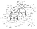
- Fig. 1 is a perspective view of the top side showing an example of the external configuration of a controller 1 according to a first embodiment of the present invention
- Fig. 2 is a perspective view of the bottom side showing an example of the external configuration of the controller 1.
- Fig. 3 is a front view showing an example of the external configuration of the controller 1
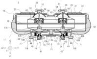
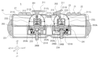
- Fig. 4 is a cross-sectional view of Fig. 3.
- the controller 1 is used to operate the game device, and is roughly composed of a flat operation section 11, a rear operation section 12, a bottom operation section 13, grip sections 14 and 15, an upper case 16, a lower case 17, and a printed circuit board 18.
- an A button 21, a B button 22, an X button 23, and a Y button 24 are arranged on the right side of the flat-surface operation unit 11.
- the xyz coordinate system in FIG. 1 is a coordinate system based on the controller 1, and in the direction perpendicular to the plane of the controller 1, for example, the direction in which the A button 21 is pressed is defined as the z1 direction, and the direction opposite to the z1 direction is defined as the z2 direction.
- the direction from the X button 23 to the B button 22 is defined as the x1 direction
- the opposite direction to the x1 direction is defined as the x2 direction
- the direction from the A button 21 to the Y button 24 is defined as the y1 direction
- the opposite direction to the y1 direction is defined as the y2 direction.
- the xyz coordinate systems in Figures 2 to 4, 7 to 9, 13, 14, 18, and 19 are the same as the xyz coordinate system in Figure 1.
- a start button 25 and a select button 26 are located in the central area of the flat-surface operation unit 11.
- a cross key 27 is located on the left side of the flat-surface operation unit 11.
- Analog sticks 28 and 29 are located below the center of the flat-surface operation unit 11.
- the A button 21, B button 22, X button 23, Y button 24, start button 25, and select button 26 protrude from the upper case 16 in the z2 direction in FIG. 1, and are buttons that can be pressed in the z1 direction.
- the cross key 27 is composed of an up button 27A, a down button 27B, a left button 27C, and a right button 27D.
- the up button 27A, the down button 27B, the left button 27C, and the right button 27D protrude from the upper case 16 in the z2 direction in FIG. 1, and are each buttons that can be pressed in the z1 direction in FIG. 1.
- Analog sticks 28 and 29 are controls that output an analog value according to the direction in which stick 54 is tilted and the angle at which stick 54 is tilted, when the operator uses his or her finger to tilt cap 51 fitted to stick 54 (see Figure 4) that is erected in the z2 direction (neutral position) in any direction, i.e., in the x1-x2 direction, y1-y2 direction, or diagonal direction (360° from the neutral position).
- the analog sticks 28 and 29 have caps 51 that protrude from the upper case 16 in the z2 direction in FIG. 1.
- the analog sticks 28 and 29 may also be capable of being pressed in the z1 direction. The detailed structure, assembly method, and operation of the analog sticks 28 and 29 will be described later with reference to FIGS. 5 to 9.
- the rear operation section 12 of the controller 1 is composed of shoulder buttons 30, 31, 32, and 33. Near the left end of the rear of the controller 1, shoulder button 30 is located on the flat side (z2 direction side), and shoulder button 31 is located on the bottom side (z1 direction side).
- a shoulder button 32 is located on the flat side (z2 direction side) near the right end of the back of the controller 1, and a shoulder button 33 is located on the bottom side (z1 direction side).
- braking units 41 and 42 that constitute the bottom operation unit 13 are disposed in the lower case 17 of the controller 1 at positions facing the analog sticks 28 and 29.
- the braking unit 41 is used to brake the analog stick 28, and the braking unit 42 is used to brake the analog stick 29.
- buttons such as the A button 21, the analog sticks 28 and 29, and the brakes 41 and 42 while holding the grip portion 14 with the left hand and the grip portion 15 with the right hand.
- An example is as follows.
- the operator can operate the select button 26, the cross key 27, and the analog stick 28 with the thumb of the left hand.
- the operator can also operate the shoulder buttons 30 and 31 with the index finger or middle finger of the left hand.
- the operator can also operate the brake unit 41 with the ring finger or middle finger of the left hand.
- the operator can operate the A button 21, B button 22, X button 23, Y button 24, start button 25, and analog stick 29 with the thumb of the right hand.
- the operator can also operate the shoulder buttons 32 and 33 with the index finger or middle finger of the right hand.
- the operator can also operate the brake unit 42 with the ring finger or middle finger of the right hand.
- FIG. 5 is a perspective view of the top side showing an example of the external configuration of the analog sticks 28 and 29, and Fig. 6 is a perspective view of the bottom side showing an example of the external configuration of the analog sticks 28 and 29. Also, Fig. 7 is an exploded perspective view of the analog sticks 28 and 29.
- Analog sticks 28 and 29 have the same structure and are constructed by assembling a cap 51, an upper case 52, an x-axis follower 53, a stick 54, a y-axis follower 55, a lower case 56, a connecting pin 57, a pressure receiving member 58, an x-axis potentiometer 59, a y-axis potentiometer 60, an x-axis centering portion 61, and a y-axis centering portion 62.
- the cap 51 is disc-shaped and is comprised of an operating part 51A that is operated by the operator's thumb, and a dome-shaped cover 51B that is integrally formed to prevent the intrusion of dust and other foreign matter.
- the upper case 52 is rectangular and open at the bottom end.
- the upper case 52 has a circular through-hole 52A formed in the center of the top surface, and notches 52B formed in the center of each side of the bottom end.
- the x-axis follower 53 is constructed by integrally connecting an arc-shaped operating part 53A, a shaft part 53B that connects to one end of the operating part 53A, and a shaft part 53C that connects to the other end of the operating part 53A.
- the operating part 53A is arc-shaped to avoid interference with the y-axis follower 55.
- a rectangular through-hole 53D is formed in the longitudinal direction of the operating part 53A.
- the stick 54 is constructed by integrally connecting cylindrical shafts 54A and 54B with a connecting portion 54C that is rectangular and is provided between shafts 54A and 54B.
- a hole 54D is formed in the center of connecting portion 54C into which connecting pin 57 fits.
- the y-axis follower 55 is constructed by integrally connecting an actuating part 55A, a shaft part 55B connected to one end of the actuating part 55A in the longitudinal direction, and a shaft part 55C connected to the other end of the actuating part 55A in the longitudinal direction.
- a rectangular through hole 55D is formed in the actuating part 55A.
- Two holes 55E into which the connecting pins 57 fit are formed in the center of the actuating part 55A in the longitudinal direction, at positions symmetrical in the lateral direction.
- the lower case 56 is square-shaped, has the same external dimensions on the flat surface as the upper case 52, and is open at the top.
- the lower case 56 has notches 56A formed in the center of each side of the top end, and has a circular through-hole 56B formed in the center of the bottom surface.
- legs 56C are formed in the lower corners of the lower case 56 for fixing it to a printed circuit board 18 (see Figure 4) on which various components are mounted.
- the connecting pin 57 is cylindrical and has the same length in the short direction as the length of the operating part 55A that constitutes the y-axis follower part 55.
- the pressure receiving member 58 is composed of a semi-spherical pressure receiving part 58A and a cylindrical connecting part 58B that are integrally formed.
- a hole 58C is formed in the center of the upper surface of the connecting part 58B into which the lower end of the shaft part 54B of the stick 54 fits.
- the end of the shaft 53C of the x-axis follower 53 is fitted into a through hole 59A formed in the center of the x-axis potentiometer 59, and outputs an electrical signal (analog value) according to the rotation of the x-axis follower 53 in the x1-x2 direction caused by tilting the stick 54.
- the y-axis potentiometer 60 has a through hole 60A formed in the center that fits over the end of the shaft 55C of the y-axis follower 55, and outputs an electrical signal (analog value) that corresponds to the rotation of the y-axis follower 55 in the y1-y2 directions that occurs when the stick 54 is tilted.
- the x-axis centering part 61 has a through hole (not shown) formed in the center, and a pair of leaf springs 61A are provided on the y2 side.
- the y-axis centering part 62 has a through hole 62A formed in the center, and a pair of leaf springs (not shown) are provided on the x2 side.
- the worker inserts the shaft 54A of the stick 54 through the through hole 52A of the upper case 52 while facing the four notches 52B of the upper case 52 to the four notches 56A of the lower case 56, thereby joining the upper case 52 and the lower case 56.
- the upper case 52 and the lower case 56 can be joined by any of the following means: adhesion, fusion, crimping, locking with locking claws and locking holes, etc.
- the worker inserts the end of the shaft portion 55B of the y-axis follower 55, which protrudes from the upper case 52 and the lower case 56 to the x2 side, into a through hole 62A formed in the center of the y-axis centering portion 62, so that it protrudes in the x2 direction, and abuts the end of the shaft portion 55B against a pair of leaf springs (not shown).
- the worker fits the upper end of the shaft 54A of the stick 54, which protrudes upward from the through-hole 52A of the upper case 52, into a hole (not shown) formed at the lower end of the operating part 51A of the cap 51.
- the worker also fits the lower end of the shaft 54B of the stick 54, which protrudes downward from the through-hole 56B of the lower case 56, into a hole 58C formed in the upper surface of the connecting part 58B of the pressure receiving member 58.
- step (f) When mounting the analog sticks 28 and 29 on the controller 1, the worker first attaches the assembly up to step (f) above by fixing the four legs 56C of the lower case 56 to the printed circuit board 18 (see Figure 4). Next, the worker solders the terminals protruding from the bottom ends of the x-axis potentiometer 59, y-axis potentiometer 60, x-axis centering portion 61, and y-axis centering portion 62 to the patterns formed on the printed circuit board 18. Next, the worker performs step (g) above.
- the x-axis follower 53 rotates in the x1 direction
- the shaft 54A of the stick 54 contacts the x2 side of the through hole 53D of the x-axis follower 53
- the x-axis follower 53 rotates in the x2 direction.
- the x-axis potentiometer 59 outputs an electrical signal (analog value) according to the rotation of the x-axis follower 53 in the x1-x2 direction.
- the y-axis follower 55 connected to the stick 54 rotates in the y1-y2 direction according to the amount of movement in the y1-y2 direction when the stick 54 is tilted.
- the y-axis potentiometer 60 outputs an electrical signal (analog value) according to the rotation of the y-axis follower 55 in the y1-y2 direction.
- the x-axis follower 53 and the y-axis follower 55 operate independently, so when the operator operates the operating part 51A of the cap 51 with his or her thumb in any direction within 360° on the xy plane, the x-axis potentiometer 59 and the y-axis potentiometer 60 output an electrical signal corresponding to that operation.
- the x-axis centering section 61 returns the stick 54 to the neutral position due to the restoring force of the leaf spring 61A that was pressed by the end of the shaft portion 53B of the x-axis follower section 53, and the y-axis centering section 62 returns the stick 54 to the neutral position due to the restoring force of the leaf spring (not shown) that was pressed by the end of the shaft portion 55B of the y-axis follower section 55.
- Figure 8 is a perspective view showing an example of the external configuration of the analog sticks 28 and 29 when tilted in the x2 direction.
- Figure 8 it is shown that the x2-direction leaf spring 61A of the x-axis centering portion 61 is curved in the x2 direction.
- Figure 9 is a perspective view showing an example of the external configuration of the analog sticks 28 and 29 when tilted in the x1 direction.
- the x1-direction leaf spring 61A of the x-axis centering portion 61 is curved in the x1 direction.
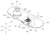
- FIG. 10 is an exploded perspective view of the braking units 41 and 42 that constitute the controller 1.
- the braking units 41 and 42 have the same structure, and are configured by assembling an operation plate 71, a pressing member 72, a coil spring 73, and an adjustment screw 74.
- the operating plate 71 has a generally I-shaped planar shape and is constructed by integrally forming a base 71A, an operating end 71B connected to one end of the base 71A, and a shaft 71C connected to the other end of the base 71A.
- a through hole 71D is formed in the approximate center of the base 71A, and a female screw 71E is formed on the inner circumferential surface of the through hole 71D.
- the pressing member 72 is configured by integrally forming a disk-shaped pressing portion 72A, a shaft portion 72B having one end connected to the pressing portion 72A, and a pair of fitting portions 72C formed on the outer periphery of the other end of the shaft portion 72B.
- Felt for example, may be attached to the upper surface of the pressing portion 72A.
- a polished metal sheet may be attached to the hemispherical surface of the pressing receiving portion 58A that constitutes the pressing receiving member 58.
- the coil spring 73 has an outer diameter smaller than the outer diameter of the pressing portion 72A of the pressing member 72, and an inner diameter larger than the distance from one fitting portion 72C to the other fitting portion 72C of the pressing member 72.
- the length of the shaft portion 72B of the pressing member 72 excluding the fitting portion 72C is slightly shorter than the free height of the coil spring 73.
- the adjustment screw 74 is configured by integrally forming a cylindrical portion 74A and a hexagonal column-shaped head 74B.
- a male thread 74C is formed on the outer peripheral surface of the cylindrical portion 74A, which screws into a female thread 71E formed on the inner peripheral surface of the through hole 71D of the operation plate 71.
- a bottomed circular hole 74D that houses the coil spring 73 is formed in the cylindrical portion 74A.
- a fitting hole 74E is formed in the bottom surface of the circular hole 74D, into which the other end of the shaft portion 72B of the pressing member 72 and a pair of fitting portions 72C fit.
- a beam 17A is formed integrally with the lower case 17 in the center of the lower case 17 and parallel to the short side direction (y1-y2 direction) of the lower case 17.
- a recess 17B1 into which the shaft 71C of the operation plate 71 is inserted to mount the operation plate 71 rotatably in the z1-z2 directions around the shaft 71C as the center of rotation, and a restriction plate 17B2 for restricting the operation plate 71 from rotating in the z1 direction by more than a predetermined angle are formed at both ends of the recess 17B1 .
- through holes 17C and 17D are formed in the lower case 17 at positions facing the pressure receiving members 58 that constitute the analog sticks 28 and 29.
- the inner diameters of the through holes 17C and 17D are large enough to allow the pressure portion 72A of the pressure member 72 that constitutes the brakes 41 and 42 to be inserted therethrough.
- a through hole (not shown) is formed in the lower case 17 at a position facing the operating end 71B of the operating plate 71 that constitutes the braking units 41 and 42, and the body 43A of the sensor pin 43 is fixed to the periphery of the through hole, and the operating unit 43B, which can be pushed in the z2 direction, protrudes in the z1 direction.
- the sensor pin 43 When the operating end 71B of the operating plate 71 is operated in the z2 direction, causing the operating end 71B to push the actuator 43B into the main body 43A, the sensor pin 43 outputs a detection signal indicating that the operating plate 71 is being operated.
- the controller 1 Based on this detection signal, the controller 1 supplies a signal indicating that the braking unit 41 or 42 is operating to the game device 2 (see FIG. 11) along with an analog value corresponding to the tilt angle of the analog stick 28 or 29.
- the game device 2 When the game device 2 does not receive a signal indicating that the brake unit 41 or 42 is operating, it employs speed control to convert the analog value into the moving speed of the character, etc. On the other hand, when a signal indicating that the brake unit 41 or 42 is operating is received, the game device 2 employs position control to convert the analog value into the distance from the origin coordinates of the character, etc.
- a cylindrical stopper 44 is provided on the bottom surface of the lower case 17 between the sensor pin 43 and the through holes 17C and 17D, protruding in the z1 direction.
- the stopper 44 may be formed integrally with the lower case 17 or may be formed separately from the lower case 17.
- the stopper 44 is provided to prevent the operation plate 71 from being operated in the z2 direction beyond a certain amount, and is provided to set an upper limit for the frictional force generated between the pressure receiving portion 58 and the pressure portion 72A.
- the upper end of the return spring 45 is attached to the bottom surface of the lower case 17 near the outer periphery of the stopper 44 so as to surround the stopper 44.
- the maximum load height (highest compression height) of the return spring 45 is slightly greater than the length of the stopper 44.
- the worker inserts the assembled set of pressing member 72, coil spring 73, and adjustment screw 74 into through hole 71D from the bottom side of operation plate 71, and screws male thread 74C of adjustment screw 74 into female thread 71E.
- the male thread 74C and female thread 71E should be screwed together to the extent that the restoring force of coil spring 73 prevents adjustment screw 74 from coming loose.
- the worker inserts the shaft portion 71C of the operation plate 71 into the recess 17B1 of the beam portion 17A of the braking portion 41 assembled as described above, and attaches it to the lower case 17.
- the worker also attaches the braking portion 42 assembled in the same manner as the braking portion 41 to the lower case 17 so as to be symmetrical to the braking portion 41 with respect to the beam portion 17A as the axis of symmetry.
- the restoring force of the return spring 45 creates a gap between the bottom surface of the pressure receiving member 58 that constitutes the analog sticks 28 and 29 and the top surface of the pressing portion 72A of the pressing member 72 that constitutes the braking units 41 and 42.
- the analog sticks 28 and 29 can be operated in any direction without being braked by the braking units 41 and 42.
- FIG. 11 is a conceptual diagram showing an example of the configuration of a game system 100 including a controller 1.
- the game system 100 includes the controller 1, a game device 2, and a display device 3.
- the game device 2 executes various processes (e.g., game processes) in the game system 100 and displays the results of the processes on the display device 3.
- the game device 2 and the controller 1 are connected by wire or wirelessly, and operation data generated when an operator operates the controller 1 is supplied from the controller 1 to the game device 2.
- the game device 2 is configured so as to be connectable to a game server (not shown) via the network 4.
- the display device 3 is configured, for example, as a liquid crystal display device or an organic EL display device.
- analog stick 28 is set to move the character or a third person in the game space
- analog stick 29 is set to move the viewpoint and aim of the character or the third person.
- FIG. 12 is a diagram showing an example of a game screen displayed on the display device 3 in an FPS shooting game.
- a part of a weapon 101 held by a character, a crosshair 102 for the weapon 101, and a monster 103 that is the target are displayed.
- the operator uses the thumb of the right hand to tilt the cap 51 of the analog stick 29 in the direction in which he or she wants to align the aim 102 with the target monster 103, thereby changing the analog value of the analog stick 29, thereby moving the aim 102 so that it overlaps with the target monster 103.
- the distance between the aim 102 and the monster 103 is small, so the operator only needs to tilt the cap 51 of the analog stick 29 slightly in the x2 direction (see Figure 1).
- the leaf spring 61A of the x-axis centering portion 61 that constitutes the analog stick 29
- the operator tilts the cap 51 of the analog stick 29 in the x2 direction (see FIG. 1) while operating the operation plate 71 that constitutes the braking unit 42 using the ring finger or middle finger of the right hand.
- This causes the pressing portion 72A of the pressing member 72 that constitutes the braking unit 42 to be pressed against the bottom surface of the pressing receiving member 58 that constitutes the analog stick 29, as shown in FIG. 13 and FIG. 14.
- frictional force is generated between the pressure receiving member 58 and the pressing portion 72A, and the operator can use this frictional force as a clue for operation to easily align the aim 102 with the monster 103 compared to when the brake portion 42 is not used.
- the operator can appropriately adjust the frictional force generated between the pressure receiving member 58 and the pressing portion 72A by applying more or less force to the operating end portion 71B with the ring finger or middle finger of the right hand while playing the game.
- the operator can adjust the upper limit of the frictional force as needed by rotating the adjustment screw 74 to change the state of engagement between the male thread 74C of the adjustment screw 74 and the female thread 71E of the operation plate 71 when not playing the game.
- the restoring force of the leaf spring 61A constituting the x-axis centering portion 61 and the leaf spring (not shown) constituting the y-axis centering portion 62 is preferably smaller than the maximum frictional force generated between the pressure receiving portion 58 and the pressing portion 72, i.e., the frictional force generated between the pressure receiving portion 58 and the pressing portion 72 when the upper surface of the operation plate 71 abuts against the lower end of the stopper 44. This is because the tilt angle of the analog stick 28 or 29 is maintained constant even if the operator removes his/her finger from the cap 51 constituting the analog stick 28 or 29 while operating the operation plate 71.
- the controller 1 comprises analog sticks 28 and 29 which output an analog value corresponding to the direction in which the stick 54 is tilted and the angle at which the stick 54 is tilted, a pressure receiving member 58 attached to the stick 54, and braking sections 41 and 42 which brake the analog sticks 28 and 29 by a pressing member 72 which can be pressed against the pressure receiving member 58.
- controller 1 outputs a signal indicating that the braking unit 41 or 42 is operating.
- the controller 1 has a cap 51 attached to one end of a stick 54 that can be tilted by the operator, a pressure receiving member 58 attached to the other end of the stick 54, an operation plate 71 that can be operated in a direction such that the brakes 41 and 42 move toward and away from the pressure receiving member 58, and a pressure member 72 attached to the operation plate 71.
- the restoring forces of the leaf spring 61A of the x-axis centering portion 61 and the leaf spring (not shown) of the y-axis centering portion 62 can be set to be weak so that even an operator with weak muscles can easily operate the analog sticks 28 and 29.
- an operator with weak muscles can easily operate the analog stick 28 or 29 by using only the restoring force of the leaf spring 61A etc. as a clue for operation, for example, by stopping the analog stick 28 or 29 midway or tilting it slowly. Also, because the restoring force of the leaf spring 61A etc. can be set to a weaker value, it becomes easier to return the analog stick 28 or 29 to the neutral position compared to the conventional method.
- the strength of the operation can be adjusted by the degree to which the operator presses the pressing member 72 against the pressing member 58, providing clues for operation according to the operator's preferences. For example, when operating the analog stick 28 or 29 to move a character or the like to a desired position, the character or the like can be accurately moved to the desired position by increasing the force with which the pressing member 72 is pressed against the pressing member 58 as the character approaches the desired position.
- the tilt angle of the analog stick 28 or 29 can be maintained constant.
- the operator operates the analog stick 28 or 29 to tilt it to the desired tilt angle, and then operates the operation plate 71 to press the pressing member 72 against the pressure receiving member 58 to the extent that the analog stick 28 or 29 comes to a stop.
- the operator does not need to continue to apply a force to the cap 51 with his/her fingers that balances the restoring force of the leaf spring 61A of the x-axis centering portion 61 and the leaf spring (not shown) of the y-axis centering portion 62, and can loosen the pressure applied to the cap 51 with his/her fingers or release his/her fingers.
- the analog stick 28 or 29 does not wobble and the operator's fingers do not shake, allowing the operator to maintain a constant tilt angle of the analog stick 28 or 29.
- the operator simply releases the finger pressing the pressing member 72.
- the tilt of the analog stick 28 or 29 near the neutral position can be reflected in the game.
- the operator need only operate the operation plate 71 to press the pressing member 72 against the pressure receiving member 58 to the extent that the analog stick 28 or 29 gradually returns to the neutral position and comes to rest.
- the x-axis centering unit 61 and the y-axis centering unit 62 do not function.
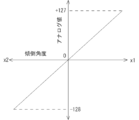
- FIG. 15 is a graph showing an example of the relationship between the tilt angle of the analog sticks 28 and 29 in the x1-x2 direction and the analog value output from the analog sticks 28 and 29.
- the controller 1 simply supplies the game device 2 with an analog value corresponding to the tilt angle of the analog stick 28 or 29 along with a signal indicating that the braking unit 41 or 42 is operating.
- the game device 2 recognizes that the braking unit 41 or 42 is operating, and so can employ the position control to, for example, slightly move a character or a shooting aim in the game space, as intended by the operator, based on the analog value supplied from the controller 1.
- the controller 1 supplies the analog value to the game device 2 together with a signal indicating that the braking unit 41 or 42 is operating.
- the game device 2 recognizes that the braking unit 41 or 42 is operating, and can use the position control to, for example, smoothly move a character or the like in the game space, as intended by the operator, based on the analog value supplied from the controller 1.
- the return operation of the analog stick 28 or 29 can be reflected in the game.
- the controller 1 supplies to the game device 2 an analog value corresponding to the tilt angle of the analog stick 28 or 29 along with a signal indicating that the braking unit 41 or 42 is operating.
- the game device 2 recognizes that the braking unit 41 or 42 is operating, and can determine that the analog value supplied from the controller 1 is due to the return operation and not due to the operation of the x-axis centering unit 61 or y-axis centering unit 62.
- the game device 2 can employ the position control to reflect the analog value resulting from the return operation in the game. For example, if the operator returns the analog stick 28 or 29 to the neutral position with the intention of moving the character, etc. in the opposite direction to the previous movement direction, the character, etc. can be moved in the opposite direction as intended by the operator. In this case, since the x-axis centering unit 61 and the y-axis centering unit 62 are not functioning, the character, etc. will not return to the center position of the game screen, and will remain in the position to which it was moved as long as the operator is operating the operation plate 71.
- the recoil caused by continuing to fire a weapon often causes the aim of the shot to move vertically and horizontally, so the player must adjust the aim of the shot each time by operating the analog stick 28 or 29.
- the operator can easily adjust the aim of the shot by slightly tilting the analog stick 28 or 29 while operating the operation plate 71 that constitutes the brake unit 41 or 42.
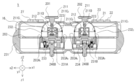
- FIG. 16 is a front view showing an example of the external configuration of the analog sticks 28 and 29 and the braking units 46 and 47 constituting a controller according to a second embodiment of the present invention.
- a braking unit 46 for braking the analog stick 28 and a braking unit 47 for braking the analog stick 29 are newly provided inside the lower case 17, instead of the braking units 41 and 42 of the first embodiment.
- the structure and operation of the other parts of the controller are similar to those of the first embodiment, and therefore a description thereof will be omitted.
- the brake unit 46 has a disk-shaped pressing member 81 and an electromagnetic actuator 82 that, when turned on, causes an operating shaft 82A to protrude and press the pressing member 81 against the pressing receiver 58 with a predetermined pressing force.
- the pressing member 81 is attached to the end of the operating shaft 82A of the electromagnetic actuator 82.
- the brake unit 46 also has a pressing member 81 and an electromagnetic actuator 83 that, when turned on, causes an operating shaft 83A to protrude and press the pressing member 81 against the pressing receiver 58 with a pressing force greater than that of the electromagnetic actuator 82.
- the pressing member 81 is attached to the end of the operating shaft 83A of the electromagnetic actuator 83.
- the braking unit 47 has the same structure as the braking unit 46.
- the number of pressing members 81 is not limited to two, and one or three or more may be provided.
- the electromagnetic actuators 82 and 83 one or more actuators with different pressing forces may be provided.
- the surface area of the pressing member attached to the electromagnetic actuator 83 may be the same as or larger than the surface area of the pressing member 81.
- Table 1 shows an example of the relationship between the on/off state of the electromagnetic actuators 82 and 83 and the frictional force generated between the pressure receiving portion 58 and the pressing member 81.
- the frictional force generated between the pressure receiving portion 58 and the pressing member 81 can be changed in four stages depending on the on/off state of the electromagnetic actuators 82 and 83.
- the on state is represented by a circle and the off state is represented by an x. The same applies to Table 2.
- buttons for turning the electromagnetic actuators 82 and 83 on and off may be provided near the electromagnetic actuators 82 and 83 at a location that can be operated with the middle or ring finger of the left or right hand.
- the function of turning the electromagnetic actuators 82 and 83 on and off may also be set in various buttons (e.g., button A 21 and button B 22) that make up the planar operation unit 11.
- the operator need only operate the analog stick 28 or 29 to tilt it to the desired tilt angle, and then press, for example, a button to turn on the electromagnetic actuator 83 in order to stop the analog stick 28 or 29.
- FIG. 17 is a front view showing an example of the external configuration of the analog sticks 28 and 29 and the brake units 46 and 47 when the electromagnetic actuator 82 is off and the electromagnetic actuator 83 is on.
- the restoring force of the leaf spring 61A constituting the x-axis centering portion 61 and the leaf spring (not shown) constituting the y-axis centering portion 62 is preferably smaller than the maximum frictional force generated between the pressure receiving portion 58 and the pressure member 81, i.e., the state in which the electromagnetic actuators 82 and 83 are both on (see the bottom row of Table 1). This is because the tilt angle of the analog stick 28 or 29 is maintained constant even if the operator removes his or her finger from the cap 51 constituting the analog stick 28 or 29 while the electromagnetic actuator 82 or 83 is on.
- the controller comprises analog sticks 28 and 29 that output an analog value corresponding to the direction in which stick 54 is tilted and the angle at which stick 54 is tilted, a pressure receiving member 58 attached to stick 54, and braking units 46 and 47 that brake analog sticks 28 and 29.
- the cap 51 which is tilted by the operator, is attached to one end of the stick 54, and the pressure receiving member 58 is attached to the other end of the stick 54.
- the brake units 46 and 47 have two pressure members 81 and electromagnetic actuators 82 and 83 that press each pressure member 81 against the pressure receiving member 58.
- the operator can obtain the effect obtained by the first embodiment by simply operating a specified button, without relying on his/her own muscle strength.
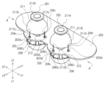
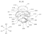
- FIG. 18 is a perspective view showing an example of the external configuration of an analog stick 84 and a braking unit 48 constituting a controller according to a third embodiment of the present invention.
- Fig. 19 is a plan view showing an example of the external configuration of the analog stick 84 and the braking unit 48 in a state in which the cap 51 is removed from the analog stick 84 in Fig. 18.
- an analog stick 84 is newly provided in place of the analog sticks 28 and 29 of the first embodiment.
- a braking unit 48 that brakes the analog stick 84 is newly provided on the printed circuit board 18 in place of the braking units 41 and 42 of the first embodiment.
- the structure and operation of the other parts of the controller are similar to those of the first embodiment, and therefore a description thereof will be omitted.
- the analog stick 84 differs from the analog sticks 28 and 29 in the following ways.
- the stick 54 is configured such that the shaft portion 54B (see FIG. 7) has been removed, and the shaft portion 54A and the connecting portion 54C are integrally connected. Also, the pressure receiving portion 58 shown in FIG. 7 has been removed.
- the shaft portion 53C constituting the x-axis driven portion 53 is inserted into the through hole 59A of the x-axis potentiometer 59, and its length is extended so as to protrude in the y1 direction.
- One end of the rotating shaft 91-1 is connected to the shaft portion 53C.
- the rotating shaft 91-1 is cylindrical except for the one end.
- the cylindrical portion of the rotating shaft 91-1 is rotatably supported by two bearings (not shown) formed in the y1-y2 direction of a square-shaped housing 93.
- a cylindrical pressing receiving portion 92-1 is fitted into the cylindrical portion of the rotating shaft 91-1 that is accommodated in the housing 93.
- the shaft portion 55C constituting the y-axis driven portion 55 is inserted into the through hole 60A (see FIG. 7) of the y-axis potentiometer 60, and its length is extended so as to protrude in the x1 direction.
- One end of the rotating shaft 912 is connected to the shaft portion 55C.
- the rotating shaft 912 is cylindrical except for the one end.
- the cylindrical portion of the rotating shaft 912 is rotatably supported by two bearings 96B (x2 side is not shown) formed in the x1-x2 direction of a square-shaped housing 96.
- a cylindrical pressing receiving portion 922 is fitted into the cylindrical portion of the rotating shaft 912 that is accommodated in the housing 96.
- the brake unit 48 is composed of an x-axis brake unit 48A that brakes the rotation of the x-axis follower unit 53 in the x1-x2 direction, and a y-axis brake unit 48B that brakes the rotation of the y-axis follower unit 55 in the y1-y2 direction.
- the x-axis braking section 48A is composed of pressing members 941 and 951 , and electromagnetic actuators 821 and 831 having the same functions as the electromagnetic actuators 82 and 83 described in the second embodiment.
- the electromagnetic actuators 821 and 831 are attached to the outside of a wall portion 93A on the x1 side of the housing 93.
- An operating shaft 821A of the electromagnetic actuator 821 is inserted into the housing 93 from a through-hole (not shown) formed in the wall portion 93A of the housing 93, and a pressing member 941 is attached to the end thereof.
- An operating shaft 831A of the electromagnetic actuator 831 is inserted into the housing 93 from a through hole (not shown) formed in a wall portion 93A of the housing 93, and a pressing member 951 is attached to the end of the operating shaft 831A.
- the pressing members 941 and 951 are both disk-shaped, and the surface area of the pressing member 951 is larger than the surface area of the pressing member 941 .
- the y-axis braking section 48B is composed of pressing members 942 and 952 , and electromagnetic actuators 822 and 832 having the same functions as the electromagnetic actuators 82 and 83 described in the second embodiment.
- the electromagnetic actuators 822 and 832 are attached to the outside of a wall portion 96A on the y1 side of a housing 96.
- An operating shaft 822A of the electromagnetic actuator 822 is inserted into the housing 96 from a through-hole (not shown) formed in the wall portion 96A of the housing 96, and a pressing member 942 is attached to the end thereof.
- An operating shaft 832A of the electromagnetic actuator 832 is inserted into the housing 96 from a through hole (not shown) formed in a wall portion 96A of the housing 96, and a pressing member 952 is attached to the end of the operating shaft 832A.
- the pressing members 942 and 952 are both disk-shaped, and the surface area of the pressing member 952 is larger than the surface area of the pressing member 942 .
- the pressing members 94-1 and 95-1 provided in the x-axis braking section 48A and the pressing members 94-2 and 95-2 provided in the y-axis braking section 48B are not limited to two each, and may be one or three or more each.
- the electromagnetic actuators 82-1 , 82-2 , 83-1 , and 83-2 may also be provided with one or more actuators with different pressing forces.
- the pressing members 94-1 , 94-2, 95-1 , and 95-2 attached to the electromagnetic actuators 82-1 , 82-2 , 83-1 , and 83-2 may have the same surface area or different surface areas .
- Buttons for turning on and off the electromagnetic actuators 821 , 822 , 831 , and 832 may be provided on the bottom side of the lower case 17 at a location that can be operated with the middle finger or ring finger of the left or right hand. Also, the function of turning on and off the electromagnetic actuators 821 , 822 , 831 , and 832 may be set to various buttons (e.g., button A 21 and button B 22) constituting the flat-surface operation unit 11.
- the restoring force of the leaf spring 61A constituting the x-axis centering portion 61 and the leaf spring (not shown) constituting the y-axis centering portion 62 is preferably smaller than the maximum frictional force generated between the pressure receiving portions 921 and 922 and the pressure members 941 , 942 , 951 and 952 , i.e., the state in which the electromagnetic actuators 821 , 822 , 831 and 832 are all ON (see the bottom row of Table 2). This is because the tilt angle of the analog stick 84 is maintained constant even if the operator releases his/her finger from the cap 51 constituting the analog stick 84 while any of the electromagnetic actuators 821 , 822 , 831 or 832 is ON.
- the controller comprises an analog stick 84 that outputs an analog value corresponding to the direction in which the stick 54 is tilted and the angle at which the stick 54 is tilted, and a braking unit 48 that brakes the analog stick 84.
- the analog stick 84 has a stick 54 that can be tilted in any direction over 360° around a neutral position in the z2 direction, an x-axis follower 53 that rotates in the x1-x2 direction as the stick 54 is tilted, and a y-axis follower 55 that rotates in the y1-y2 direction as the stick 54 is tilted.
- the pressure receiving member 92-1 is attached to the x-axis follower 53, and the pressure receiving member 92-2 is attached to the y-axis follower 55.
- the braking unit 48 is made up of an x-axis braking unit 48A and a y-axis braking unit 48B.
- the x-axis braking unit 48A is made up of pressing members 94-1 and 95-1 , and electromagnetic actuators 82-1 and 83-1
- the y-axis braking unit 48B is made up of pressing members 94-2 and 95-2 , and electromagnetic actuators 82-2 and 83-2 .
- the pressing member 94-1 is pressed against the pressure receiving member 92-1 by the electromagnetic actuator 82-1
- the pressing member 94-2 is pressed against the pressure receiving member 92-2 by the electromagnetic actuator 82-2
- the pressing member 95-1 is pressed against the pressure receiving member 92-1 by the electromagnetic actuator 83-1
- the pressing member 95-2 is pressed against the pressure receiving member 92-2 by the electromagnetic actuator 83-2 .
- the operator can obtain the effects obtained by the first embodiment by simply operating the button, without relying on his/her own muscle strength.
- the analog stick 84 does not have the shaft portion 54B and the pressure receiving portion 58, so that the thickness of the entire controller in the z1-z2 direction can be made thinner, and versatility is high.
- the operator can brake the x-axis follower 53 and the y-axis follower 55 separately and independently.
- the pressure receiving member 922 attached to the y-axis follower 55 rotates, but the pressure receiving member 921 attached to the x-axis follower 53 does not rotate. Therefore, even if the pressing members 941 and 951 are pressed against the pressure receiving member 921 , the force required to tilt the analog stick 84 in the y1 direction or the y2 direction does not change.
- the program can forcibly turn on the electromagnetic actuators 82-2 and 83-2 to clearly inform the operator of the existence of the said restriction.
- the external configuration of a controller according to a fourth embodiment of the present invention does not differ from the external configuration of the controller 1 shown in Figures 1 to 3 except that analog sticks 201 and 202 (see Figure 20, etc.) are newly provided instead of the analog sticks 28 and 29. That is, in the fourth embodiment, the braking unit 41 shown in Figures 1 to 3 is used to brake the analog stick 201, and the braking unit 42 shown in Figures 1 to 3 is used to brake the analog stick 202.
- FIG. 20 is a top perspective view showing an example of the configuration of the analog sticks 201 and 202 and the printed circuit board 203 to which they are attached that constitute a controller according to a fourth embodiment of the present invention.
- FIG. 21 is a bottom perspective view showing an example of the configuration of the analog sticks 201 and 202 and the printed circuit board 203 shown in FIG. 20, and
- FIG. 22 is a cross-sectional view taken along the line A-A in FIG. 20.
- the xyz coordinate system in FIGS. 20 to 22 and FIGS. 27 to 29 described below is the same as the xyz coordinate system in FIG. 1.
- the printed circuit board 203 is formed with through holes 203A -1 to 203A- 8 into which the respective tilt transmission members 204-1 to 204-8 are inserted.
- the suffixes "1 to 8" of the tilt transmission members 204 1 to 204 8 , the holes 211C 1 to 211C 8 of the cap 211 and the holes 206C 1 to 206C 8 of the pressure receiving member 206 are given for convenience to correspond to the suffixes "1 to 8" of the through holes 203A 1 to 203A 8 of the printed circuit board 203 in order to clarify the attachment state of the tilt transmission member 204 to the cap 211 and the pressure receiving member 206.
- the through holes 203A1 to 203A8 of the printed circuit board 203 are given the suffixes "1 to 4" in the order of the x2 side, y1 side, x1 side and y2 side at the mounting position of the analog stick 201, and the suffixes "5 to 8" in the order of the x2 side, y1 side, x1 side and y2 side at the mounting position of the analog stick 202.
- the tilt transmission members 204-1 to 204-8 are of the same shape, material and dimensions, the cap 211 and the pressure receiving member 206 are both symmetrical in shape, and the suffixes "1 to 8" of each reference numeral have no meaning before mounting on the printed circuit board 203. However, after mounting on the printed circuit board 203, this means that the through holes 203A- 1 to 203A- 8 of the printed circuit board 203 are attached to each other with the same suffixes " 1 to 8".
- the tilt transmission members 204-1 to 204-8 are collectively referred to, the term tilt transmission member 204 is used.
- the tilt transmission members 204 1 to 204 8 are bendable but have low elasticity.
- the shape of the tilt transmission members 204 1 to 204 8 may be , for example, a thread, a twisted combination of multiple types of thread-like members, a plate shape, or a rod shape.
- the material of the tilt transmission members 204 1 to 204 8 may be, for example, natural fibers, synthetic fibers such as polyvinylidene fluoride, natural or synthetic fibers coated with natural or synthetic materials, metal, or a combination of natural fibers, synthetic fibers, and metal.
- the tilt transmission members 204 1 to 204 8 do not need to be of the same shape, material, or dimensions overall, and may have different shapes, materials, or dimensions depending on the areas where they are used (e.g., areas that may come into contact with other members).
- a guide/support member 205 and a pressure receiving member 206 are provided on the bottom side of the printed circuit board 203 at a position facing the analog sticks 201 and 202.
- the guide/support member 205 is attached to the bottom surface of the printed circuit board 203.
- the guide/support member 205 guides the tilt transmission members 204.sub.1 to 204.sub.8 to the pressure receiving member 206, and supports the pressure receiving member 206.
- Figure 23 is a perspective view of the bottom side showing an example of the configuration of the guide/support member 205.
- the guide/support member 205 is composed of a cylindrical central portion 205A, four arm portions 205B, and four cylindrical end portions 205C, which are integrally formed.
- One end of each arm portion 205B is connected to the outer circumferential surface near the upper end of the central portion 205A, at positions symmetrical to each other with respect to the central portion 205A. This gives the guide/support member 205 a cross shape when viewed in a plane.
- a cylindrical end 205C is formed at the other end of each arm 205B.
- a through hole 205D is formed in each cylindrical end 205C, into which the corresponding tilt transmission member 204 is inserted.
- the inner circumferential surface of each through hole 205D is smoothly finished so that the tilt transmission member 204 does not wear down due to friction when it comes into contact with the through hole 205D.
- a support recess 205E is formed on the bottom surface of the central portion 205A.
- the tip 206D of the cylindrical portion 206B constituting the pressure receiving member 206 abuts against the support recess 205E, and the tilt transmission member 204 is stretched between the cap 211 and the pressure receiving member 206, so that the guide/support member 205 supports the pressure receiving member 206 so that it can rotate freely with the support recess 205E as a fulcrum.
- the pressure receiving member 206 is configured by integrally forming a hemispherical shell portion 206A with an open upper end and a cylindrical portion 206B that is vertically erected at the lowest part of the inner surface of the hemispherical shell portion 206A.
- Four holes 206C are formed near the upper end of the hemispherical shell portion 206A at positions symmetrical to each other with respect to the cylindrical portion 206B.
- the other end of the corresponding tilt transmission member 204 is attached to each hole 206C.
- the tip portion 206D of the cylindrical portion 206B is hemispherical. The surface of the tip portion 206D is smoothly finished so that the pressure receiving member 206 rotates smoothly in accordance with the tilting operation of the analog sticks 201 and 202.
- Fig. 25 is an exploded perspective view showing an example of the configuration of the analog sticks 201 and 202.
- the analog sticks 201 and 202 have the same structure and are composed of a cap 211 and an analog stick unit 212.
- a commercially available or known analog stick unit can be used for the analog stick unit 212, and the structure is not limited to the structure shown in Fig. 25.
- a known analog stick unit is disclosed in, for example, Japanese Patent No. 7113133.
- the coordinate system in FIG. 25 is the coordinate system for the analog sticks 201 and 202 alone.
- an axis parallel to a first line passing through corners a and b on the flat surface side is defined as a first axis A1.
- An axis parallel to a second line passing through corners a and c on the flat surface side and perpendicular to the first line is defined as a second axis A2.
- An axis parallel to a third line passing through corner a on the flat surface side and corner d on the bottom surface side and perpendicular to the first and second lines is defined as a third axis A3.
- the direction from angle b to angle a is defined as the A11 direction, and the opposite direction of the A11 direction is defined as the A12 direction.
- the direction from angle c to angle a is defined as the A21 direction, and the opposite direction of the A21 direction is defined as the A22 direction.
- the direction from angle a to angle d is defined as the A31 direction, and the opposite direction of the A31 direction is defined as the A32 direction.
- the analog sticks 201 and 202 may be attached to the flat surface of the printed circuit board 203 so that they are symmetrical with respect to a plane parallel to the y1-y2 direction (direction perpendicular to the paper surface) shown in Figure 22.
- the A11-A12 direction of the A1-A3 coordinate system of the analog stick 201 is parallel to the y1-y2 direction of the xyz coordinate system
- the A11-A12 direction of the A1-A3 coordinate system of the analog stick 202 is parallel to the x1-x2 direction of the xyz coordinate system.
- the cap 211 is configured by integrally forming an operating section 211A, which is disk-shaped and operated by the operator's thumb, and a cover 211B, which is a hemispherical shell with an open bottom end and prevents dust and the like from entering the inside of the controller.
- the diameter of the cover 211B is equal to the diameter of the hemispherical shell section 206A constituting the pressing member 206.
- Four holes 211C are formed near the bottom end of the cover 211B, at positions symmetrical to each other with respect to the center of the cover 211B. Only two holes 211C are shown in FIG. 25.
- One end of each of the tilt transmission members 204 1 to 204 8 shown in FIG. 20 to FIG. 22 is attached to each hole 211C.
- the analog stick unit 212 is constructed by assembling an upper case 221, a first axis follower 222, a stick 223, a second axis follower 224, a lower case 225, a connecting pin 226, a centering part 227, a first axis potentiometer 228, and a second axis potentiometer 229.
- the upper case 221 is rectangular and open at the bottom.
- the upper case 221 has a circular through hole 221A formed in the center of the plane, and has notches 221B formed in the center of each side of the bottom end. Only two notches 221B are shown in Figure 25.
- the first shaft follower 222 is configured by integrally forming an arc-shaped operating part 222A, a shaft part 222B that connects to one end of the operating part 222A, and a shaft part 222C that connects to the other end of the operating part 222A.
- the operating part 222A is arc-shaped to avoid interference with the second shaft follower 224.
- a rectangular through hole 222D is formed in the longitudinal direction of the operating part 222A.
- the stick 223 is composed of a cylindrical portion 223A, a rectangular column portion 223B, and a disk portion 223C, which are integrally formed.
- a hole 223D into which the connecting pin 226 fits is formed near the bottom end of the rectangular column portion 223B.
- the second shaft driven part 224 is constructed by integrally forming an actuating part 224A, a shaft part 224B connected to one end of the actuating part 224A in the longitudinal direction, and a shaft part 224C connected to the other end of the actuating part 224A in the longitudinal direction.
- a rectangular through hole 224D is formed in the actuating part 224A.
- Two holes 224E into which the connecting pins 226 fit are formed at positions symmetrical in the short direction at the center of the longitudinal direction of the actuating part 224A.
- the lower case 225 is square-shaped, with the outer dimensions of its planar side being the same as those of the upper case 221, and open at the top.
- the lower case 225 has notches 225A formed in the center of each side of the upper end, and a circular bottomed hole 225B formed in the center of the bottom surface.
- legs 225C are formed in the lower corners of the lower case 225 for fixing it to a printed circuit board 203 (see Figure 20) on which various components are mounted.
- the connecting pin 226 is cylindrical and has a length equal to the short-side length of the actuating portion 224A that constitutes the second shaft follower portion 224.
- Figure 26 is a bottom perspective view showing an example of the configuration of centering portion 227.
- Centering portion 227 is configured by integrally forming disk portion 227A and four leaf spring portions 227B.
- the outer diameter of disk portion 227A is approximately equal to the outer diameter of disk portion 223C constituting stick 223, and is slightly smaller than the inner diameter of bottomed hole 225B of lower case 225.
- Each leaf spring portion 227B is cut into a plate shape so that base portion 227C remains at the four corners of the bottom surface of disk portion 227A, and tip portion 227D faces base portion 227C of adjacent leaf spring portion 227B, and tip portion 227D is pulled out diagonally downward.
- the first axis potentiometer 228 shown in FIG. 25 has an end of the shaft 222C of the first axis follower 222 fitted into a through hole 228A formed in the center, and outputs an electrical signal (analog value) corresponding to the rotation of the first axis follower 222 in the A11-A12 direction caused by tilting the stick 223.
- the second axis potentiometer 229 has a through hole 229A formed in the center, into which the end of the shaft portion 224B of the second axis follower 224 is fitted, and outputs an electrical signal (analog value) corresponding to the rotation of the second axis follower 224 in the A21-A22 direction caused by tilting the stick 223.
- the worker inserts the cylindrical portion 223A of the stick 223 into the through hole 221A of the upper case 221 while facing the four notches 221B of the upper case 221 to the four notches 225A of the lower case 225, thereby joining the upper case 221 and the lower case 225.
- the upper case 221 and the lower case 225 can be joined by any of the following means: adhesion, fusion, crimping, locking with locking claws and locking holes, etc.
- first axis follower 222 When the upper case 221, first axis follower 222, stick 223, second axis follower 224, lower case 225, connecting pin 226, and centering part 227 are assembled, the end of shaft part 222C of first axis follower 222 protrudes from the upper case 221 and lower case 225 toward the A21 side. Also, in this state, the end of shaft part 224B of second axis follower 224 protrudes from the upper case 221 and lower case 225 toward the A12 side.
- the worker attaches the two analog stick units 212 to the printed circuit board 203 so that they are symmetrical with respect to a plane parallel to the y1-y2 direction (a direction perpendicular to the paper surface), as shown in FIG. 22.
- the worker attaches another guide/support member 205 to the bottom surface of the printed circuit board 203, at a position facing the analog stick unit 212 on the x1 side, so that the axes of the through holes 203A5 to 203A8 are aligned with the axes of the four through holes 205D formed in the guide/support member 205.
- the guide/support members 205 may be attached to the printed circuit board 203 by any of fitting, adhesion, screw fastening, locking with locking tabs and locking holes, etc.
- the upper ends of the cylindrical ends 205C of the guide/support members 205 are fitted into the through holes 203A1 , 203A3 , 203A5 , and 203A7 of the printed circuit board 203.
- the analog sticks 201 and 202, tilt transmission member 204, guide/support member 205, and pressure receiving member 206 are mounted on the printed circuit board 203, as shown in Figures 20 to 22.
- FIG. 27 is a perspective view of the top side showing an example of the configuration of the analog stick 201 when not tilted, the analog stick 202 when tilted in the x2 direction, the printed circuit board 203, etc.
- Fig. 28 is a perspective view of the bottom side showing an example of the configuration of the analog sticks 201 and 202 and the printed circuit board 203, etc. shown in Fig. 27, and
- Fig. 29 is a cross-sectional view taken along the line A-A in Fig. 27.
- the analog sticks 201 and 202 mounted as described above tilt the stick 223 fitted into the hole 211D formed at the bottom end of the operating portion 211A of the cap 211.
- the leaf spring portion 227B of the centering portion 227 is pressed downward by the disk portion 223C of the stick 223.
- the first axis follower 222 rotates in the x1 direction
- the first axis follower 222 rotates in the x2 direction
- the first axis potentiometer 228 outputs an electrical signal (analog value) according to the rotation of the first axis follower 222 in the x1-x2 direction.
- the second axis follower 224 connected to the stick 223 rotates in the y1-y2 direction according to the amount of movement in the y1-y2 direction when the stick 223 is tilted.
- the second axis potentiometer 229 outputs an electrical signal (analog value) according to the rotation of the second axis follower 224 in the y1-y2 direction.
- the first axis follower 222 and the second axis follower 224 operate independently, so when the operator operates the operating part 211A of the cap 211 with his or her thumb in any direction within 360° on the xy plane, the first axis potentiometer 228 and the second axis potentiometer 229 output an electrical signal in response to that operation.
- the centering portion 227 returns the stick 223 to the neutral position due to the restoring force of the leaf spring portion 227B that was being pressed by the disc portion 223C of the stick 223.
- a cap 51 and a pressure receiving member 58 are attached to the upper and lower ends of the stick 54, and the pressing portion 72 of the braking portion 41 or 42 is pressed against the pressure receiving member 58 as the member to be braked, i.e., the pressing member 72 is pressed against the pressure receiving member 58 as the member to be braked to suppress the movement of the pressure receiving member 58, thereby braking the analog stick 28 or 29.
- a cap 211 is attached to the upper end of the stick 223, and the cap 211 and the pressure receiving member 206 are connected by a tilt transmission member 204, and the pressing portion 72 of the braking portion 41 or 42 is pressed against the pressure receiving member 206; in other words, the pressing member 72 is pressed against the pressure receiving member 206 as the braked member to suppress the movement of the pressure receiving member 206, thereby braking the analog stick 201 or 202.
- the controller comprises analog sticks 201 and 202 which output an analog value corresponding to the direction in which stick 223 is tilted and the angle at which stick 223 is tilted, a cap 211 attached to one end of stick 223, a pressure receiving member 206 attached to cap 211 as a braked member, and braking units 41 and 42 which brake analog sticks 201 and 202 by pressing a pressure member 72 against pressure receiving member 206 to suppress movement of pressure receiving member 206.
- the fourth embodiment provides the same effect as the first embodiment.
- a commercially available or well-known analog stick unit such as the analog stick unit 212 can be used, so the controller can be developed, designed, and manufactured at lower cost and in a shorter period of time than the controller 1 according to the first embodiment.
- Figure 30 is a perspective view of the top side showing an example of the external configuration of a controller 5 according to a fifth embodiment of the present invention
- Figure 31 is a perspective view of the bottom side showing an example of the external configuration of the controller 5.
- Figure 32 is a cross-sectional view taken along line B-B of Figure 30.
- parts corresponding to the parts in Figures 1 to 4 are given the same reference numerals, and their description will be omitted.
- the xyz coordinate system in Figures 30 to 32 and Figures 33, 34, and 39 described later is the same as the xyz coordinate system in Figure 1.
- the external configuration of the planar side of the controller 5 shown in FIG. 30 is generally similar to the external configuration of the planar side of the controller 1 shown in FIG. 1, except that analog sticks 201 and 202 (see FIG. 25) have been newly provided in place of the analog sticks 28 and 29, and that a lower case 231 has been newly provided in place of the lower case 17.
- the analog sticks 201 and 202 of the fourth embodiment are used in place of the analog sticks 28 and 29 of the first embodiment.
- the shoulder buttons 30 to 33 shown in FIG. 1 are not shown in FIG. 30.
- the external configuration of the bottom side of the controller 5 shown in FIG. 31 differs from the external configuration of the bottom side of the controller 1 shown in FIG. 2 in that a lower case 231 is newly provided instead of the lower case 17, and in that braking parts 41 and 42 are not provided.
- the lower case 231 does not have a portion corresponding to the beam part 17A shown in FIG. 2.
- through holes 231A and 231B are formed in the lower case 231 at positions facing the analog sticks 201 and 202.
- FIG. 33 is a perspective view of the top side showing an example of the configuration of the analog sticks 201 and 202, the braking units 233 and 234, and the printed circuit board 203 to which they are attached, which constitute the controller 5.
- FIG. 34 is a perspective view of the bottom side showing an example of the configuration of the analog sticks 201 and 202, the braking units 233 and 234, and the printed circuit board 203, etc. shown in FIG. 33.
- the analog sticks 201 and 202 and the printed circuit board 203 according to the fourth embodiment are used as they are, but instead of the tilt transmission members 204-1 to 204-8 , the guide/support member 205, the pressure receiving member 206, and the braking sections 41 and 42 according to the fourth embodiment, tilt transmission members 232-1 to 232-4 and braking sections 233 and 234 are newly provided.
- the tilt transmission members 232 1 to 232 4 are collectively referred to as tilt transmission member 232.
- the shape and material of the tilt transmission member 232 are similar to the shape and material of the tilt transmission member 204.
- the meaning of the suffixes " 1 to 8" in each of the holes 211C1 to 211C8 of the cap 211 and the meaning of the suffixes "1 to 4" in the tilt transmission members 2321 to 2324 are the same as the meaning of the suffixes " 1 to 8" in each of the tilt transmission members 2041 to 2048 , the holes 211C1 to 211C8 of the cap 211, and the holes 206C1 to 206C8 of the pressure receiving member 206, as explained in the fourth embodiment.
- Fig. 32 shows only the tilt transmission members 2321 and 2323 and the through holes 203A1 , 203A3 , 203A5 , and 203A7 .
- Fig. 33 shows only the through holes 203A3 , 203A4 , 203A7 , and 203A8 .
- Braking units 233 and 234 are attached to the bottom surface of the printed circuit board 203 at positions facing the analog sticks 201 and 202.
- the braking units 233 and 234 press the tilt transmission member 232 in the z2 direction to brake the analog stick 201 or 202.
- the tilt transmission members 204.sub.1 to 204.sub.4 have one end attached to holes 211C.sub.1 to 211C.sub.4 formed in the cap 211, and pass through opposing through holes 203A.sub.1 to 203A.sub.4 in the printed circuit board 203, and have the other end attached to holes 206C.sub.1 to 206C.sub.4 formed in positions facing the holes 211C.sub.1 to 211C.sub.4 in the hemispherical shell portion 206A.
- the tilt transmission members 204.sub.5 to 204.sub.8 are each attached at one end to a hole 211C.sub.5 to 211C.sub.8 formed in the cap 211, and pass through opposing through holes 203A.sub.5 to 203A.sub.8 in the printed circuit board 203, and each attached at the other end to a hole 206C.sub.5 to 203A.sub.8 formed in a position facing the hole 211C.sub.5 to 211C.sub.8 in the hemispherical shell portion 206A .
- one end of the tilt transmission member 232-1 is attached to a hole 211C- 1 (see FIG. 32) formed on the x2 side of the cap 211, passes through an opposing through-hole 203A- 1 in the printed circuit board 203, enters the inside of the braking portion 233 from the x2 side, exits from the x2 side of the braking portion 233, passes through through-hole 203A -3 , and has the other end attached to a hole 211C- 3 (see FIGS. 32 and 33) formed on the x1 side of the cap 211.
- one end of the tilt transmission member 232-2 is attached to a hole 211C- 2 (not shown) formed on the y1 side of the cap 211, passes through an opposing through-hole 203A- 2 (not shown) in the printed circuit board 203, enters the inside of the braking portion 233 from the y1 side, exits from the y2 side of the braking portion 233, passes through through-hole 203A- 4 , and has the other end attached to a hole 211C- 4 (see FIG. 33) formed on the y2 side of the cap 211.
- one end of the tilt transmission member 232-3 is attached to a hole 211C- 5 (see Figure 32) formed on the x2 side of the cap 211, passes through the opposing through-hole 203A- 5 of the printed circuit board 203 and enters the inside of the braking part 234 from the x2 side, exits from the x2 side of the braking part 234 and passes through through-hole 203A -7 , and the other end is attached to a hole 211C- 7 (see Figures 32 and 33) formed on the x1 side of the cap 211.
- one end of the tilt transmission member 232-4 is attached to a hole 211C- 6 (not shown) formed on the y1 side of the cap 211, passes through an opposing through-hole 203A- 6 (not shown) in the printed circuit board 203, enters the inside of the braking portion 234 from the y1 side, exits from the y2 side of the braking portion 234, passes through through-hole 203A -8 , and has the other end attached to a hole 211C- 8 (see FIG. 33) formed on the y2 side of the cap 211.
- the analog sticks 201 and 202 are indirectly braked by pressing the pressing member 72 against the pressing receiving member 206 attached to the analog sticks 201 and 202 via the tilt transmission members 204-1 to 204-8 to suppress the movement of the pressing receiving member 206 as the braked member.
- the braking units 233 and 234 are used to adjust the tension of the tilt transmission member 232 attached to the analog sticks 201 and 202, that is, the movement of the tilt transmission member 232 as the braked member is suppressed, thereby indirectly braking the analog sticks 201 and 202.
- Figure 35 is an exploded perspective view showing an example of the configuration of the brake units 233 and 234.
- the brake units 233 and 234 have the same structure, and are configured by assembling a housing 241, four bolts 242, four nuts 243, four adjustment springs 244, two tension adjustment members 245, four nuts 246, two return springs 247, a brake member 248, a cover 249, and five screws 250.
- the coordinate system in Fig. 35 is a coordinate system for braking portions 233 and 234 alone.
- an axis parallel to a first straight line passing through guide portions 241B1 and 241B3 described below is defined as a first axis A1.
- An axis parallel to a second straight line passing through guide portions 241B2 and 241B4 described below and perpendicular to the first straight line is defined as a second axis A2.
- An axis parallel to a third straight line perpendicular to the first and second straight lines is defined as a third axis A3.
- the direction from guide portion 241B3 to guide portion 241B1 is defined as the A11 direction, and the opposite direction to the A11 direction is defined as the A12 direction.
- the direction from guide portion 241B4 to guide portion 241B2 is defined as the A21 direction, and the opposite direction to the A21 direction is defined as the A22 direction.
- the direction from the top surface side to the bottom surface side is defined as the A31 direction, and the opposite direction to the A31 direction is defined as the A32 direction.
- the reason why the A1-A3 coordinate system of the braking parts 233 and 234 alone is different from the xyz coordinate system based on the controller is the same as the A1-A3 coordinate system of the analog sticks 201 and 202 alone in Figure 25.
- the A1-A3 coordinate system in Figures 36 to 38, which will be described later, is the same as the A1-A3 coordinate system in Figure 35.
- FIG. 36 is a perspective view of the planar side showing an example of the configuration of the housing 241.
- Through holes 241AA 1 to 241AA 4 into which four bolts 242 are respectively inserted are formed in a housing main body 241A of the housing 241.
- Bottomed holes against which the bottom surfaces of the heads of the respective bolts 242 abut are formed around the upper ends of the through holes 241AA 1 to 241AA 4 .
- guide portions 241B 1 to 241B 4 are formed integrally with the housing main body 241A, symmetrically with respect to the center of the housing main body 241A and at positions which correspond to the through holes 203A 1 to 203A 4 or the through holes 203A 5 to 203A 8 of the printed circuit board 203 when the housing 241 is mounted on the printed circuit board 203.
- Through holes 241BA 1 to 241BA 4 are formed in the A31-A32 direction of each of the guide portions 241B 1 to 241B 4.
- the guide portion 241B 1 and the guide portion 241B 3 are combined, and the guide portion 241B 2 and the guide portion 241B 4 are combined to guide the tilt transmission member 232 into and out of the housing main body 241A.
- the tilt transmission member 232 inserted from one of the through holes 241BA1 or 241BA3 or 241BA2 or 241BA4 is guided into the housing main body 241A and is guided from the other through hole 241BA3 or 241BA1 or 241BA4 or 241BA2 to the outside of the housing main body 241A.
- mating projections 241C1 to 241C4 are integrally formed with the corresponding guide portions 241B1 to 241B4 .
- the mating projections 241C1 to 241C4 are configured by integrally forming mating portions 241CA1 to 241CA4 and abutment portions 241CB1 to 241CB4 connected to the lower ends of the corresponding mating portions 241CA1 to 241CA4 .
- the fitting portions 241CA 1 to 241CA 4 are cylindrical and have corresponding through holes 241BA 1 to 241BA 4 formed in their centers .
- the contact portions 241CB1 to 241CB4 are cylindrical with an outer diameter larger than that of the corresponding fitting portions 241CA1 to 241CA4 , and have corresponding through holes 241BA1 to 241BA4 formed in their centers.
- the corresponding fitting portions 241CA1 to 241CA4 are fitted into the through holes 203A1 to 203A4 or the through holes 203A5 to 203A8 of the printed circuit board 203, the upper surfaces of the contact portions 241CB1 to 241CB4 become the bottom surfaces of the printed circuit board 203, and come into contact with the peripheries of the through holes 203A1 to 203A4 or the through holes 203A5 to 203A8 .
- Contact portions 241D1 and 241D2 are formed integrally with the housing body 241A near the center and ends of the top surface of the housing body 241A.
- the contact portions 241D1 and 241D2 have different outer diameters, but are both cylindrical.
- the contact portions 241CB 1 to 241CB 4 and 241D 1 and 241D 2 are formed on the bottom side of the printed circuit board 203 in order to avoid interference with parts and soldered portions mounted in positions opposite the braking portions 233 and 234 .
- the bottom side of the housing body 241A is formed with an accommodation section 241E that accommodates the adjustment spring 244, tension adjustment member 245, return spring 247, braking member 248, etc.
- Five circular holes 241F are formed on the periphery of the bottom side of the housing body 241A for attaching the cover 249 to the bottom surface of the housing 241.
- Each nut 243 is screwed onto each bolt 242 and is used to secure the corresponding bolt 242 to the housing 241.
- each tension adjustment member 245 has through holes 245A near both ends into which the bolts 242 are inserted.
- a protrusion 245B is formed in the center of the upper surface of each tension adjustment member 245 to adjust the tension of the tilt transmission member 232 when the braking parts 233 and 234 are not in use by being pressed against the tilt transmission member 232.
- Each adjustment spring 244 is loosely fitted to each bolt 242, and is used to maintain the tension adjustment state of the tilt transmission member 232 by each tension adjustment member 245 through its restoring force.
- Each nut 246 is screwed onto each bolt 242, and is used to adjust the tension of the tilt transmission member 232 by each tension adjustment member 245 depending on the degree of screwing.
- the braking member 248 is configured by integrally forming a pressing portion 248A and a cylindrical braking button 248B.
- the pressing portion 248A is configured by integrally forming pressing protrusions 248C1 to 248C3 , pressing protrusions 248D1 and 248D2 , and plate portions 248E1 and 248E2 .
- the pressing protrusions 248C1 to 248C3 are arranged side by side at the same height on a first straight line parallel to the A11-A12 direction, and a groove 248C4 is formed between the pressing protrusions 248C2 and 248C3 .
- the pressing protrusions 248D1 and 248D2 are arranged side by side at the same height on a second straight line that is perpendicular to the first straight line and parallel to the A21-A22 direction.
- the pressing protrusions 248C1 to 248C3 are guided to the accommodation portion 241E of the housing main body 241A and pressed against one of the tilt transmission members 232 arranged on the first straight line.
- the pressing protrusions 248D1 and 248D2 are guided to the accommodation portion 241E of the housing main body 241A and pressed against the other of the tilt transmission members 232 arranged on the second straight line.
- the groove 248C4 is formed to prevent the two orthogonal tilt transmission members 232 from contacting each other. Meanwhile, inside the accommodating portion 241E of the housing 241A body, for the same reason as the groove 248C4 , protrusions 241G1 and 241G3 having a first height and protrusions 241G2 and 241G4 having a second height higher than the first height are formed integrally with the housing body 241A (see FIG. 38).
- Each return spring 247 shown in Figure 35 is accommodated between the accommodation portion 241E of the housing 241 and the plate portions 248E1 and 248E2 (see Figure 37) of the pressing portion 248A that constitutes the braking member 248, and is used to return the operated braking member 248 to its original position by its restoring force.
- the cover 249 has the same outer diameter shape and dimensions as the housing 241 in order to cover the entire bottom surface of the housing 241.
- the cover 249 is configured by integrally forming a cover main body 249A and extension portions 249B 1 to 249B 4.
- a through hole 249C into which the brake button 248B of the brake member 248 is loosely fitted is formed in approximately the center of the cover main body 249A.
- Five through holes 249D are formed in the cover main body 249A at positions corresponding to the five circular holes 241F formed on the periphery of the bottom surface side of the housing main body 241A.
- Each screw 250 is inserted into each through hole 249D of the cover body 249A and screwed into the corresponding circular hole 241F of the housing body 241A, thereby attaching the cover 249 to the housing 241.
- the worker attaches one of the housings 241 by fitting the fitting portions 241CA 3 , 241CA 2 , 241CA 1 and 241CA 4 formed in the housing 241 into the through holes 203A 1 to 203A 4 of the printed circuit board 203, respectively.
- the worker also attaches the other housing 241 by fitting the fitting portions 241CA 4 , 241CA 3 , 241CA 3 and 241CA 1 formed on the housing 241 into the through holes 203A 5 to 203A 8 of the printed circuit board 203, respectively.
- each housing 241 attaches to the bottom surface of the printed circuit board 203 so that they are symmetrical about a plane parallel to the y1-y2 direction, as shown in Figures 32 and 34.
- each housing 241 can be attached to the printed circuit board 203 by any of the following means: adhesion, screw fastening, locking with locking tabs and locking holes, etc.
- the contact portions 241CB 1 to 241CB 4 , 241D 1 and 241D 2 formed on each housing 241 come into contact with the bottom surface of the printed circuit board 203 .
- the worker also attaches one end of each of the tilt transmission members 232 3 and 232 4 to holes 211 C 5 and 211 C 6 formed in the vicinity of the lower end of the cover 211 B of the cap 211 that constitutes the analog stick 202 .
- the worker attaches the other end of the tilt transmission member 232 1 to the hole 211 C 3 formed in the vicinity of the lower end of the cover 211 B of the cap 211 that constitutes the analog stick 201 .
- the worker attaches the other end of the tilt transmission member 232 2 to the hole 211 C 4 formed near the lower end of the cover 211 B of the cap 211 that constitutes the analog stick 201 so that the tension is the same as that of the tilt transmission member 232 1 .
- FIG. 38 is a perspective view of the bottom side showing an example of the configuration of the housing 241 into which the tilt transmission members 232 1 and 232 2 are inserted.
- the worker performs steps similar to those of (g) to (i) above on the housing 241 attached to the analog stick 202 and the through holes 203A5 to 203A8 of the printed circuit board 203, thereby attaching the tilt transmission members 2323 and 2324 to the housing 241.
- the operator operates the analog sticks 201 and 202 to check the tension of the tilt transmission members 232-1 to 232-4 .
- the operator changes the state of engagement of the nut 246 with the bolt 242 to change the state of contact of the convex portion 245B of the tension adjustment member 245 with the tilt transmission members 232-1 to 232-4 , thereby adjusting the tension of the tilt transmission members 232-1 to 232-4 .
- the worker aligns the axis of the five through holes 249D of the cover 249 with the axis of the five circular holes 241F of the housing 241, and while pressing the return spring 247 with the cover 249 and braking member 248, inserts each screw 250 into each through hole 249D of the cover 249 and screws it into each circular hole 241F of the housing 241, thereby attaching the cover 249, braking member 248, and return spring 247 to the housing 241.
- the analog sticks 201 and 202, the tilt transmission members 232 1 to 232 4 and the brake parts 233 and 234 are mounted on the printed circuit board 203 as shown in FIGS.
- Figure 39 is a cross-sectional view of the controller 5, and shows a state in which the analog stick 201 is not tilted, a state in which the analog stick 202 is tilted in the x2 direction, a state in which the brake unit 233 is not operated, and a state in which the brake unit 234 is operated.
- the two tilt transmission members 232 are attached at both ends to two pairs of opposing holes 211C formed in the cover 211B of the cap 211 that constitutes the analog stick 201, and are stretched perpendicularly at a predetermined distance within the braking section 233 provided on the bottom side of the printed circuit board 203. The same is true for the analog stick 202 and the braking section 234.
- the operator uses the middle or ring finger of the right hand to press the brake button 248B located on the bottom side of the controller 5 in the z2 direction against the restoring force of the return spring 247.
- the pressing protrusions 248D1 and 248D2 that constitute the braking member 248 are pressed against the tilt transmission member 2323 , and the pressing protrusions 248C1 to 248C3 are pressed against the tilt transmission member 2324 , thereby braking the analog stick 202.
- the tilted state of the analog stick 202 in the x2 direction is maintained.
- the operator simply removes the middle or ring finger of his/her right hand from the braking button 248B. This causes the braking button 248B to be pushed back in the z1 direction by the restoring force of the return spring 247, and the braking portion 234 is released from pressing the tilt transmission members 232-3 and 232-4 .
- the method of operating the analog sticks 201 and 202 is the same as in the first embodiment except as described above, so a description of this method will be omitted.
- the controller 5 comprises analog sticks 201 and 202 that output an analog value corresponding to the direction in which the stick 223 is tilted and the angle at which the stick 223 is tilted, a cap 211 attached to one end of the stick 223, tilt transmission members 232.sub.1 to 232.sub.4 as braked members attached to the cap 211, and braking units 233 and 234 that brake the analog sticks 201 and 202 by pressing a braking member 248 against the tilt transmission members 232.sub.1 to 232.sub.4 to suppress the movement of the tilt transmission members 232.sub.1 to 232.sub.4 .
- the same effects as those obtained by the fourth embodiment can be obtained.
- the guide/support member 205 and the pressure receiving member 206 according to the fourth embodiment are removed, and most of the members that suppress the movement of the tilt transmission members 232.sub.31 to 232.sub.4 can be housed compactly in the brake parts 233 and 234. Therefore, according to the fifth embodiment, the thickness of the entire controller 5 in the z1-z2 direction can be made thinner than that of the controller according to the fourth embodiment, and the controller is highly versatile.
- Figure 40 is a perspective view of the top side showing an example of the external configuration of a controller 6 according to a sixth embodiment of the present invention
- Figure 41 is a perspective view of the bottom side showing an example of the external configuration of the controller 6.
- parts corresponding to the parts in Figures 30 to 32 are given the same reference numerals, and their description will be omitted.
- the xyz coordinate system in Figures 40 and 41, and Figures 42 to 44 and Figures 49 to 51 described later, is the same as the xyz coordinate system in Figure 1.
- the external configuration of the planar side of the controller 6 shown in FIG. 40 is generally similar to the external configuration of the planar side of the controller 5 shown in FIG. 30, except that a lower case 251 has been newly provided in place of the lower case 231. Note that, like FIG. 30, the shoulder buttons 30 to 33 shown in FIG. 1 are not shown in FIG. 40.
- the external configuration of the bottom side of controller 6 shown in FIG. 41 differs from the external configuration of the bottom side of controller 5 shown in FIG. 31 in that a lower case 251 is newly provided instead of lower case 231, a portion of brake button 248B constituting brake units 233 and 234 does not protrude downward, and switches 261 to 264 are newly provided for controlling brake units 254 to 257, which will be described later.
- braking units 254 to 257 that brake the analog sticks 201 and 202 are newly provided and housed inside the controller 6, instead of the braking units 233 and 234.
- Figure 42 is a perspective view of the top side showing an example of the configuration of the analog sticks 201 and 202, braking units 254 and 256, and the printed circuit board 252 on which they are attached, which constitute the controller 6.
- FIG. 43 is a bottom perspective view showing an example of the configuration of the analog sticks 201 and 202, the braking units 255 and 257, the printed circuit board 252, etc.
- FIG. 44 is a plan view showing an example of the configuration of the analog sticks 201 and 202, the braking units 254 and 256, the printed circuit board 252, etc.
- the analog sticks 201 and 202 according to the fifth embodiment are used as is. Also, in the sixth embodiment, a printed circuit board 252, braked members 253 1 to 253 4 , and braking portions 254 to 257 are newly provided in place of the printed circuit board 203, tilt transmission members 232 1 to 232 4 , and braking portions 233 and 234 according to the fifth embodiment.
- the braked members 253 1 to 253 4 are collectively referred to as braked members 253.
- the shape and material of the braked members 253 are similar to the shape and material of the tilt transmitting members 204 and 232.
- the braking units 233 and 234 are used to simultaneously adjust the tension of the two tilt transmission members 232 attached to the analog sticks 201 and 202, i.e., the movement of the two tilt transmission members 232 as braked members is simultaneously suppressed, thereby indirectly braking the analog sticks 201 and 202.
- the braking units 254 to 257 are used to separately adjust the tension of the two braked members 253 that are attached to the analog sticks 201 and 202 and perpendicular to the x1-x2 direction and the y1-y2 direction, i.e., the analog sticks 201 and 202 are indirectly braked by separately suppressing the movement of the two braked members 253.
- the braking portion 254 is attached to the flat surface of the printed circuit board 252, and adjusts the tension of the braked member 253-1 attached to holes 211C- 1 and 211C- 3 of the cap 211 that constitutes the analog stick 201, thereby braking the tilt of the analog stick 201 in the x1-x2 directions.
- the braking portion 255 is attached to the bottom surface of the printed circuit board 252, and adjusts the tension of the braked member 253-2 attached to the holes 211C- 2 and 211C- 4 of the cap 211 that constitutes the analog stick 201, thereby braking the tilt of the analog stick 201 in the y1-y2 directions.
- the braking portion 256 is attached to the flat surface of the printed circuit board 252, and adjusts the tension of the braked member 253.3 attached to the holes 211C.sub.5 and 211C.sub.7 of the cap 211 that constitutes the analog stick 202, thereby braking the tilt of the analog stick 202 in the x1-x2 directions.
- the braking portion 257 is attached to the bottom surface of the printed circuit board 252, and adjusts the tension of the braked member 2534 attached to the holes 211C6 and 211C8 of the cap 211 that constitutes the analog stick 202, thereby braking the tilt of the analog stick 202 in the y1-y2 directions.
- the meaning of the suffixes " 1 to 8" in each of the holes 211C1 to 211C8 of the cap 211 and the meaning of the suffixes " 1 to 4" in the braked members 2531 to 2534 are the same as the meaning of the suffixes " 1 to 8" in each of the tilt transmission members 2041 to 2048 , the holes 211C1 to 211C8 of the cap 211, and the holes 206C1 to 206C8 of the pressure receiving member 206, as explained in the fourth embodiment.
- the suffix "Lx” means that the tilt in the x1-x2 direction of the analog stick 201 provided on the x2 side of the controller 6, i.e., the left side, is braked.
- the suffix "Ly” means that the tilt in the y1-y2 direction of the analog stick 201 is braked.
- the suffix "Rx” means that the tilt of the analog stick 202 on the x1 side of the controller 6, i.e., on the right side, in the x1-x2 direction is damped. Also, the suffix "Ry” means that the tilt of the analog stick 202 in the y1-y2 direction is damped.
- Through holes 252A1 to 252A4 are formed in the printed circuit board 252.
- the through holes 252A1 to 252A4 are formed in the same positions as the through holes 203A2 , 203A4 , 203A6 , and 203A8 of the printed circuit board 203 described in the fourth and fifth embodiments.
- a braked member 2532 is inserted into the through holes 252A1 and 252A2
- a braked member 2534 is inserted into the through holes 252A3 and 252A4 .
- Fig. 42 only the through holes 252A2 and 252A4 are shown, while in Fig. 43, only the braked members 2532 and 2534 are shown, and in Fig. 44, only the braked members 2531 and 2533 are shown.
- one end of the braked member 253-1 is attached to a hole 211C- 1 (not shown) formed on the x2 side of the cap 211.
- the braked member 253-1 After hanging down from the hole 211C- 1 , the braked member 253-1 passes through a guide member 258-1 (see FIG. 44) provided at a position on the printed circuit board 252 opposite the hole 211C- 1 , and then has its path changed in the y1 direction to enter the braking section 254 from the x2 side.
- the handling of the braked member 253-1 within the braking section 254 will be described later with reference to FIG. 45.
- the braked member 253-1 exits from the x1 side of the braking portion 254, passes through a guide member 258-2 provided at a position on the printed circuit board 252 opposite a hole 211C- 3 (see FIG. 42) formed on the x1 side of the cap 211 , has its path changed in the z2 direction, and then the other end is attached to the hole 211C- 3 .
- one end of the tilt transmission member 2322 is attached to a hole 211C2 (not shown) formed on the y1 side of the cap 211.
- the tilt transmission member 2322 hangs down from the hole 211C2 and then passes through a through hole 252A1 (see FIG. 44) provided on the printed circuit board 252 at a position opposite the hole 211C2 , and reaches the bottom side of the printed circuit board 252.
- a guide member 259 is attached to the bottom surface of the printed circuit board 252 at a position on the line connecting the through holes 252A1 and 252A2 .
- through holes 259A and 259B having axes coinciding with the axes of the through holes 252A1 and 252A2 are formed.
- a guide portion 259C that guides the braked member 253.2 that has passed through the through hole 259A to the braking portion 255
- a guide portion 259D that guides the braked member 253.2 that has come out of the braking portion 255 to the through hole 259B side.
- the braked member 2532 that has passed through the through hole 252A1 of the printed circuit board 252 passes through the through hole 259A of the guide member 259, and is then guided by the guide portion 259C to the braking portion 255.
- the handling of the braked member 2532 within the braking portion 255 will be described later with reference to FIG.
- the braked member 253-2 coming out of the braking portion 255 is guided toward the through hole 259B by the guide portion 259D, and then passes through the through hole 259B and comes out onto the flat side through the through hole 252A -2 of the printed circuit board 252, and the other end is attached to the hole 211C- 4 (see Figure 42) formed on the y2 side of the cap 211.
- one end of the braked member 253.3 is attached to a hole 211C.sub.5 (not shown ) formed on the x2 side of the cap 211.
- the braked member 253.3 passes through a guide member 258.sub.3 (see FIG. 44) provided at a position on the printed circuit board 252 opposite the hole 211C.sub.5 , its path is changed in the y1 direction, and it enters the braking section 256 from the x2 side.
- the handling of the braked member 253.3 within the braking section 256 will be described later with reference to FIG. 45.
- the braked member 2533 exits from the x1 side of the braking portion 256, passes through a guide member 2584 provided at a position on the printed circuit board 252 opposite a hole 211C7 (see Figure 42) formed on the x1 side of the cap 211, has its path changed in the z2 direction, and then has the other end attached to the hole 211C7 .
- one end of the tilt transmission member 232-4 is attached to a hole 211C- 6 (not shown) formed on the y1 side of the cap 211.
- the tilt transmission member 232-4 hangs down from the hole 211C- 6 and then passes through a through hole 252A- 3 (see FIG. 44) provided on the printed circuit board 252 at a position opposite the hole 211C- 6 , and reaches the bottom side of the printed circuit board 252.
- a guide member 259 is attached so as to be symmetrical with the guide member 259 on the braking section 255 side with respect to a plane parallel to the y1-y2 direction.
- the braked member 253-4 which has passed through the through hole 252A- 3 of the printed circuit board 252, passes through the through hole 259B of the guide member 259, and is then guided by the guide portion 259D to the braking portion 257.
- the handling of the braked member 253-4 within the braking portion 257 will be described later with reference to FIG.
- the braked member 253-4 coming out of the braking portion 257 is guided by the guide portion 259C toward the through hole 259A side, passes through the through hole 259A, and comes out to the flat side from the through hole 252A- 4 of the printed circuit board 252, and the other end is attached to the hole 211C- 8 (see Figure 42) formed on the y2 side of the cap 211.
- [Structure of Brake Parts 254 to 257] 45 is a plan view showing an example of the configuration of the braking units 254 to 257.
- the braking units 254 to 257 have the same structure, and are configured by assembling a base plate 271, a motor 272, a bearing 273, a worm 274, a pressing member 275, a rotating shaft 276, a stopper 277, and a guide member 278.
- the base plate 271 is generally rectangular and flat.
- a motor 272 is attached to a flat surface near one corner of the base plate 271 via a mounting member 272B (see Figures 42 and 43) so that the rotation shaft 272A is parallel to the longitudinal direction of the base plate 271.
- a mounting member 272B see Figures 42 and 43
- guide portions 271A and 271B that guide the braked member 253 are integrally formed on both ends of the long side opposite the attachment position of the motor 272.
- a worm 274 is fitted to the rotating shaft 272A of the motor 272.
- One end of the rotating shaft 272A is supported by a bearing 273.
- a cord 272C is connected to one end of the motor 272, and power is supplied to the motor 272 from the printed circuit board 252 via a connector 272D.
- a pressing member 275 having a worm wheel portion 275A that screws into the worm 274 at a right angle is provided near the worm 274 and is supported by a rotating shaft 276.
- the axis of the rotating shaft 276 is perpendicular to the axis of the rotating shaft 272A.
- the pressing member 275 is formed integrally with the worm wheel portion 275A and the tongue portion 275B.
- the arcuate side of the tongue portion 275B is formed with a pressing groove portion 275C (see FIG. 42) for adjusting the tension of the braked member 253 by pressing it against the braked member 253.
- the tongue portion 275B has flat side surfaces 275D and 275E formed on the side that connects with the worm wheel portion 275A.
- a cylindrical stopper 277 is attached near the bearing 273.
- the flat side surface 275D of the pressing member 275 abuts against the stopper 277, thereby restricting the rotation of the pressing member 275 in the B direction.
- Worm gears have the advantage that even if you try to rotate the worm 274 from the worm wheel portion 275A side, a self-locking phenomenon occurs and the gear will not operate, and that there is less backlash than with other gear mechanisms.
- the tension of the braked member 253 can be kept constant even when the motor 272 is stopped.
- Two guide members 278 are provided near each of the guide portions 271A and 271B of the base plate 271. Each guide member 278 is provided so that the surface through which the braked member 253 is inserted is perpendicular to the surface through which the braked member 253 is inserted in the guide portions 271A and 271B, and is parallel to the short side direction of the base plate 271.
- the braked member 253 1 that has entered the braking portion 254 is guided by the guide portion 271 B, and is guided by a guide member 278 provided nearby, and is changed in direction so as to be parallel to the longitudinal direction of the base plate 271 .
- the braked member 253-1 comes into contact with the pressing groove portion 275C (see FIG. 42) formed on the arcuate side surface of the tongue-shaped portion 275B constituting the pressing member 275, reaches the opposing guide member 278, is guided by the guide member 278 to the guide portion 271A, is changed in direction so as to be parallel to the short side direction of the base plate 271, and then comes out of the braking portion 254.
- the braked members 253-2 and 253-3 that enter the braking portions 255 and 256 are handled in the same manner as the braked member 253-1 that enters the braking portion 254.
- the braked member 253-4 that enters the braking portion 257 is handled in the opposite manner to the braked member 253-1 that enters the braking portion 254, entering through the guide portion 271A and exiting through the guide portion 271B.
- FIG. 46 is a block diagram showing an example of the configuration of a control unit 265 that controls a motor 272 constituting the braking units 254 to 257 based on signals SNF Lx , SNF Ly , SNF Rx and SNF Ry indicating the on or off state of the switches 261 to 264 .
- the control section 265 is made up of a control circuit 281, drive circuits 282Lx , 282Ly , 282Rx , and 282Ry , and current detection circuits 283Lx , 283Ly , 283Rx , and 283Ry .
- control circuit 281 drive circuits 282Lx , 282Ly , 282Rx , and 282Ry , and current detection circuits 283Lx , 283Ly , 283Rx , and 283Ry .
- the control circuit 281 is composed of, for example, a microcomputer.
- a control circuit that executes various processes in the controller 6 may be configured to execute the functions of the control circuit 281.
- the control circuit 281 supplies the corresponding drive circuit 282 with a signal SSM for starting or stopping the corresponding motor 272, and a signal RPR for indicating the direction of rotation (forward or reverse) of the motor 272.
- Each drive circuit 282 is composed of, for example, an amplifier. Based on the signal SSM and the signal RPR supplied from the control circuit 281, each drive circuit 282 supplies or stops power to the corresponding motor 272 via the corresponding current detection circuit 283 in order to start or stop the corresponding motor 272 according to the specified rotation direction.
- FIG. 47 is a diagram showing an example of the current consumption characteristics of a certain motor 272.
- the motor 272 When the motor 272 is rotated forward, the current consumption of the motor 272 increases sharply in the start-up section ST as shown in Figure 47, and then decreases.
- the pressing member 275 rotates in the direction A shown in Figure 45, and the pressing groove portion 275B of the tongue-shaped portion 275B constituting the pressing member 275 presses the braked member 253.
- the load (rotational resistance) of the motor 272 increases, and the current consumption gradually increases.
- each current detection circuit 283 supplies a signal DOC indicating this to the control circuit 281.
- the control circuit 281 supplies a signal SSM to the corresponding drive circuit 282 based on the signal DOC supplied from each current detection circuit 283 to stop the corresponding motor 272.
- FIG. 48 is a flowchart for explaining the braking process executed by the control circuit 281. Note that the process of each step in the flowchart shown in Fig. 48 is merely an example, and the order of the process of each step may be changed, or another process may be executed in addition to (or instead of) the process of each step, as long as the same result is obtained.
- step S1 When the controller 6 is powered on, the control circuit 281 first proceeds to step S1 shown in FIG. 48, where it determines whether a certain switch (e.g., switch 261) has been turned on and a signal SNF indicating that the switch is on has been supplied. If the determination result in step S1 is "YES", the control circuit 281 proceeds to step S2.
- a certain switch e.g., switch 261
- step S2 the control circuit 281 supplies a signal RPR to the drive circuit 282 corresponding to the signal SNF to indicate the direction of rotation of the corresponding motor 272 (in this case, forward rotation), and then proceeds to step S3.
- step S3 the control circuit 281 supplies a signal SSM to the drive circuit 282 corresponding to the signal SNF to start the corresponding motor 272, and then proceeds to step S4.
- the drive circuit 282 to which the signal SSM and the signal RPR are supplied from the control circuit 281, supplies power to the corresponding motor 272 via the corresponding current detection circuit 283 in order to start the corresponding motor 272 in the forward direction.
- the corresponding current detection circuit 283 monitors the current consumption of the corresponding motor 272.
- step S4 the control circuit 281 determines whether the switch has been turned off and whether a signal SNF indicating that the switch is off has been supplied. If the determination result in step S4 is "NO", the control circuit 281 proceeds to step S5.
- step S5 the control circuit 281 determines whether or not a signal DOC indicating that the current consumption has reached the overcurrent level LOC has been supplied from the current detection circuit 283 corresponding to the switch. If the determination result in step S5 is "YES", the control circuit 281 proceeds to step S6.
- step S6 the control circuit 281 supplies a signal SSM to the drive circuit 282 corresponding to the signal DOC to stop the corresponding motor 272. After that, the control circuit 281 returns to step S4 and repeats the processes from step S4 onwards.
- the control circuit 281 supplies a signal SSM Ry to the drive circuit 282 Ry for stopping the motor 272 Ry , and then returns to step S4.
- the drive circuit 282 Ry stops supplying power to the motor 272 Ry via the current detection circuit 283 Ry , and the motor 272 Ry stops.
- step S5 if the result of the determination in step S5 is "NO", that is, if the signal DOC is not supplied from the current detection circuit 283 corresponding to the switch, the control circuit 281 returns to step S4 and repeats the processes from step S4 onwards.
- step S1 determines whether the switch is on or not supplied after power is applied to the controller 6. If the result of the determination in step S1 is "NO", that is, if a certain switch (e.g., switch 261) is not turned on and a signal SNF indicating that the switch is on is not supplied after power is applied to the controller 6, the control circuit 281 proceeds to step S7.
- a certain switch e.g., switch 261
- step S4 determines whether the switch is turned off and a signal SNF indicating that the switch is off is supplied. If the determination result in step S4 is "YES", that is, if the switch is turned off and a signal SNF indicating that the switch is off is supplied, the control circuit 281 also proceeds to step S7.
- step S7 the control circuit 281 supplies a signal RPR to the drive circuit 282 corresponding to the signal SNF to indicate the direction of rotation of the corresponding motor 272 (in this case, reverse rotation), and then proceeds to step S8.
- step S8 the control circuit 281 supplies a signal SSM to the drive circuit 282 corresponding to the signal SNF to start the corresponding motor 272, and then proceeds to step S9.
- the drive circuit 282 to which the control circuit 281 has supplied the signals SSM and RPR, supplies power to the corresponding motor 272 via the corresponding current detection circuit 283 in order to start the corresponding motor 272 in reverse rotation.
- the corresponding current detection circuit 283 also monitors the current consumption of the corresponding motor 272.
- step S9 the control circuit 281 determines whether the switch has been turned on and a signal SNF indicating that the switch is on has been supplied. If the determination result in step S9 is "NO", the control circuit 281 proceeds to step S10.
- step S10 the control circuit 281 determines whether or not a signal DOC indicating that the current consumption has reached the overcurrent level LOC has been supplied from the current detection circuit 283 corresponding to the switch. If the determination result in step S10 is "YES", the control circuit 281 proceeds to step S11.
- step S11 the control circuit 281 supplies a signal SSM to the drive circuit 282 corresponding to the signal DOC to stop the corresponding motor 272. After that, the control circuit 281 returns to step S9 and repeats the processes from step S9 onwards.
- step S10 determines whether the signal DOC is not supplied from the current detection circuit 283 corresponding to the switch. If the signal DOC is not supplied from the current detection circuit 283 corresponding to the switch, the control circuit 281 returns to step S9 and repeats the processes from step S9 onwards.
- step S9 determines whether the switch is turned on and a signal SNF indicating that the switch is on is supplied. If the determination result in step S9 is "YES", that is, if the switch is turned on and a signal SNF indicating that the switch is on is supplied, the control circuit 281 proceeds to step S2 and repeats the processing from step S2 onwards.
- the control circuit 281 executes the braking process described above in parallel in response to the operation of all switches 261 to 264.
- FIG. 49 is a perspective view of the top side showing an example of the configuration of the analog sticks 201 and 202, braking units 254 and 256, printed circuit board 252, etc. that constitute the controller 6.
- FIG. 50 is a perspective view of the bottom side showing an example of the configuration of the analog sticks 201 and 202, the braking units 255 and 257, the printed circuit board 252, etc.
- FIG. 51 is a plan view showing an example of the configuration of the analog sticks 201 and 202, the braking units 254 and 256, the printed circuit board 252, etc.
- Figures 49 to 51 show the state where the analog stick 201 is not tilted and the state where the analog stick 202 is tilted in the x2 direction. Also, Figures 49 and 51 show the state where the brake unit 254 is not operating and the state where the brake unit 256 is operating. Furthermore, Figure 50 shows the state where neither the brake units 255 nor 257 are operating.
- the operator uses the middle or ring finger of the right hand to turn on the switch 263 located on the bottom side of the controller 6.
- a signal SNF_Rx indicating that the switch 263 is on is supplied to the control circuit 281, and in the flow chart shown in FIG. 48, the control circuit 281 passes through the determination process of step S1 and proceeds to step S2.
- step S2 the control circuit 281 supplies a signal RPR_Rx to the drive circuit 282_Rx for instructing the rotation direction of the motor 272_Rx (forward rotation in this case), and in step S3, supplies a signal SSM_Rx for starting the motor 272_Rx .
- the drive circuit 282Rx to which the signals SSM_Rx and RPR_Rx are supplied, supplies power to the motor 272Rx via the current detection circuit 283Rx in order to start the motor 272Rx in the normal rotation.
- the motor 272Rx rotates in the normal direction, so that the pressing member 275 rotates in the A direction shown in FIG. 45, and the pressing groove portion 275C presses the braked member 2533 so as to increase the tension of the braked member 2533 .
- step S5 the determination result in step S5 becomes "YES".
- control circuit 281 proceeds to step S6 and supplies a signal SSM_Rx to the drive circuit 282_Rx to stop the motor 272_Rx .
- the drive circuit 282_Rx stops the supply of power to the motor 272_Rx via the current detection circuit 283_Rx , and the motor 272_Rx stops.
- the worm gear formed by the worm 274 and the worm wheel portion 275A does not operate due to the self-lock phenomenon, so the tension of the braked member 253_3 is kept constant and the tilted state of the analog stick 202 in the x2 direction is maintained.
- step S7 the control circuit 281 supplies a signal RPR Rx to the drive circuit 282 Rx for instructing the rotation direction of the motor 272 Rx (reverse rotation in this case), and in step S8 supplies a signal SSM Rx for starting the motor 272 Rx .
- the drive circuit 282Rx to which the signals SSMRx and RPRRx have been supplied, supplies power to the motor 272Rx via the current detection circuit 283Rx in order to start the motor 272Rx in the reverse direction.
- the motor 272Rx rotates in the reverse direction, so that the pressing member 275 rotates in the B direction shown in FIG. 45, and the pressing groove 275B reduces the pressure on the member to be braked 253 so as to relax the tension on the member to be braked 253.
- step S10 the signal DOC Rx is supplied from the current detection circuit 283 Rx , and the determination result in step S10 becomes "YES".
- control circuit 281 proceeds to step S11 and supplies a signal SSM_Rx to the drive circuit 282_Rx for stopping the motor 272_Rx .
- the drive circuit 282_Rx stops the supply of power to the motor 272_Rx via the current detection circuit 283_Rx , and the motor 272_Rx stops. This makes it possible to reduce current consumption.
- the method of operating the analog sticks 201 and 202 is the same as in the first embodiment except as described above, so a description of this method will be omitted.
- the controller 6 comprises analog sticks 201 and 202 that output an analog value corresponding to the direction in which the stick 223 is tilted and the angle at which the stick 223 is tilted, braked members 253 1 to 253 4 attached to a cap 211 attached to one end of the stick 223, and braking units 254 to 257 that brake the analog sticks 201 and 202 by suppressing the movement of the braked members 253 1 to 253 4 .
- the braked members 253 1 to 253 4 include braked members 253 1 and 253 3 that move in the x1-x2 directions as the stick 223 is tilted, and braked members 253 2 and 253 4 that move in the y1-y2 directions as the stick 223 is tilted.
- Braking portions 254 to 257 each have a worm wheel portion 275A, a pressing member 275 that presses braked members 253-1 to 253-4 , a worm 274 that screws into worm wheel portion 275A, and a motor 272 that rotates worm 274.
- Braking portions 254 and 256 constitute a first inhibiting portion of claim 9, and braking portions 255 and 257 constitute a second inhibiting portion of claim 9.
- the operator can obtain the same effect as that obtained by the fourth embodiment by simply operating the button without relying on his/her own muscle strength. Also, according to the sixth embodiment, the operator can brake the first axis follower 222 and the second axis follower 224 separately and independently, so that the same effect as that obtained by the third embodiment can be obtained.
- the external configuration of a controller according to a seventh embodiment of the present invention is no different from the external configuration of the controller 6 shown in Figures 40 and 41, except that analog sticks 301 and 302 (see Figure 52, etc.) are newly provided instead of the analog sticks 201 and 202. That is, in the seventh embodiment, switches 261 to 264 are used to respectively control braking units 304 to 307, which will be described later.
- FIG. 52 is a top perspective view showing an example of the configuration of analog sticks 301 and 302 and printed circuit board 303 to which they are attached that constitute a controller according to a seventh embodiment of the present invention.
- FIG. 53 is a bottom perspective view showing an example of the configuration of analog sticks 301 and 302 and printed circuit board 303 shown in FIG. 52.
- the xyz coordinate system in FIGS. 52 and 53 and in FIGS. 55 and 56 described below is the same as the xyz coordinate system in FIG. 1.
- An auxiliary braking unit 321-1 constituting braking unit 304 that brakes tilting of analog stick 301 in the x1-x2 directions is provided near the y1 side of analog stick 301.
- an auxiliary braking unit 321-2 constituting braking unit 305 that brakes tilting of analog stick 301 in the y1-y2 directions is provided near the x2 side of analog stick 301.
- auxiliary braking unit 321-3 constituting braking unit 306 that brakes tilt of analog stick 302 in the x1-x2 directions is provided near the y1 side of analog stick 302.
- auxiliary braking unit 321-4 constituting braking unit 307 that brakes tilt of analog stick 302 in the y1-y2 directions is provided near the x1 side of analog stick 302.
- the structure of auxiliary braking units 321-1 to 321-4 will be described later with reference to Figures 55 and 56.
- the printed circuit board 303 has through holes 303A 1 to 303A 4 into which the braking members 323 1 to 323 4 are inserted formed in the vicinity of the auxiliary braking portions 321 1 to 321 4 , respectively. Only the through holes 303A 1 , 303A 3 and 303A 4 are shown in FIG.
- the braking members 323 1 to 323 4 are collectively referred to as braking member 323.
- the shape and material of the braking member 323 are similar to those of the tilt transmitting members 204 and 232 and the braked member 253.
- main braking portion 322-1 constituting braking portion 304 On the bottom surface of printed circuit board 303, at positions facing auxiliary braking portions 321-1 to 321-4 , main braking portion 322-1 constituting braking portion 304, main braking portion 322-2 constituting braking portion 305, main braking portion 322-3 constituting braking portion 306, and main braking portion 322-4 constituting braking portion 307 are attached.
- the structure of main braking portions 322-1 to 322-4 will be described later with reference to FIG.
- Guide members 308-1 to 308-4 are fitted into through holes 303A - 1 to 303A- 4 and attached to the bottom surface of printed circuit board 303 near main braking section 322-1 to main braking section 322-4 , respectively.
- Guide members 308-1 to 308-4 are configured with L-shaped tubes.
- Guide members 308-1 to 308-4 guide braking members 323-1 to 323-4 inserted from through holes 303A -1 to 303A- 4 to the corresponding main braking section 322-1 to main braking section 322-4 .
- the operation control of braking units 304 to 307 when switches 261 to 264 are turned on or off is performed by a control unit 265 shown in Fig. 46 in the sixth embodiment. That is, in the seventh embodiment, motors 342Lx , 342Ly , 342Rx, and 342Ry , which constitute main braking units 3221 to 3224 and will be described later, are controlled instead of motors 272Lx , 272Ly , 272Rx , and 272Ry shown in Fig. 46.
- the meanings of the suffixes “Lx, Ly, Rx, and Ry” of motors 342Lx , 342Ly , 342Rx , and 342Ry constituting main braking units 322-1 to 322-4 are the same as the meanings of the suffixes “Lx, Ly, Rx, and Ry” of motors 272Lx , 272Ly , 272Rx , 272Ry , etc. described in the sixth embodiment.
- control circuit 281 constituting the control unit 265 shown in FIG. 46 executes the braking process of the braking units 304 to 307 according to the flowchart shown in FIG. 48.
- Fig. 54 is a perspective view of the bottom side showing an example of the configuration of the analog sticks 301 and 302.
- the A1-A3 coordinate system in Fig. 54 is similar to the A1-A3 coordinate system in Fig. 25, but differs in that it is rotated 90 degrees clockwise around the third axis A3 as the rotation axis.
- FIG. 54 parts corresponding to the analog sticks 201 and 202 shown in FIG. 25 are given the same reference numerals, and their explanations are omitted.
- the analog sticks 301 and 302 differ from the analog sticks 201 and 202 in the following ways.
- cap 311 has been newly provided in place of cap 211.
- shaft portion 222C constituting first axis driven portion 222 is inserted into through hole 228A of first axis potentiometer 228, and its length is extended so that it protrudes in the A12 direction.
- shaft portion 224B constituting second axis driving portion 224 is inserted into through hole 229A (not shown) of second axis potentiometer 229, and its length is extended so that it protrudes in the A21 direction.
- analog stick unit 212 constituting the analog sticks 301 and 302 shown in FIG. 54
- analog stick 84 shown in FIG. 18 and FIG. 19 described in the third embodiment may be used with the cap 51 removed.
- the cap 311 is disc-shaped and comprises an operating section 311A that is operated by the operator's thumb, and a cover 311B that is a semi-spherical shell with an open bottom end and is formed integrally with the controller to prevent dust and other foreign matter from entering the controller.
- Four arc-shaped cutouts 311C are formed at the bottom end of the cover 311B, at positions symmetrical to one another about the center of the cover 311B. Each cutout 311C is arc-shaped to avoid interference with the shaft 222C of the first shaft driven section 222 and the shaft 224B of the second shaft driving section 224.
- Fig. 55 is a planar perspective view showing an example of the configuration when the cap 311 and upper case 221 are removed from the analog stick 302 shown in Fig. 52.
- Fig. 56 is a planar perspective view enlarging a portion C in Fig. 55, that is, a perspective view showing an example of the configuration of the analog stick 302, the auxiliary braking unit 321-3 constituting the braking unit 306, and the auxiliary braking unit 321-4 constituting the braking unit 307.
- the auxiliary braking units 321-1 to 321-4 have the same structure, and therefore will be described below without the subscripts to avoid complication.
- the auxiliary braking unit 321 is constructed by assembling a brake rotor 331 as a braked member, a shaft support member 332, and a fixed member 333.
- the brake rotor 331 is disk-shaped, and a through hole (not shown) formed in the center is fitted with the shaft portion 222C constituting the first shaft driven unit 222 or the shaft portion 224B constituting the second shaft driving unit 224.
- the shaft portion 222C or the shaft portion 224B is rotatably supported by the shaft support member 332.
- the braking member 323 is fixed to the shaft support member 332 via a fixing member 333.
- the braking member 323 is wrapped around the brake rotor 331 and inserted into a through hole 303A formed near the auxiliary braking section 321, and reaches the bottom side of the printed circuit board 303.
- Figure 57 is an enlarged bottom view of part D on the bottom side of Figure 53, that is, a bottom view showing an example of the configuration of main braking section 322-4 that constitutes braking section 307. Since main braking sections 322-1 to 322-4 have the same structure, the following description will be given omitting subscripts to avoid complication.
- the main braking section 322 is constructed by assembling a base plate 341, a motor 342, a bearing 343, a worm 344, a winder 345, a rotating shaft 346, and stoppers 347 and 348.
- the base plate 341 is generally rectangular and flat.
- a motor 342 is attached to a flat surface near one corner of the base plate 341 via a mount member 342B (see FIG. 53) so that the rotation shaft 342A is parallel to the longitudinal direction of the base plate 341.
- a worm 344 is fitted to the rotating shaft 342A of the motor 342.
- One end of the rotating shaft 342A is supported by a bearing 343.
- a cord 342C is connected to one end of the motor 342, and power is supplied to the motor 342 from the printed circuit board 303 via a connector 342D.
- a winder 345 having a worm wheel portion 345A that screws into the worm 344 at a right angle is provided near the worm 344 and is supported by a rotating shaft 346.
- the axis of the rotating shaft 346 is perpendicular to the axis of the rotating shaft 342A.
- the winder 345 is configured by integrally forming the worm wheel portion 345A and the disk portion 345B.
- the brake member 323 is inserted into the through hole 303A of the printed circuit board 303 and guided by the guide member 308, and is wound around the circumferential surface of the disk portion 345B, with the other end fixed to the disk portion 345B.
- Flat side surfaces 345D and 345E are formed on the side of the disk portion 345B that connects with the worm wheel portion 345A.
- Cylindrical stoppers 347 and 348 are attached near winder 345.
- Flat side surface 345D of winder 345 abuts stopper 347, restricting rotation of winder 345 in direction A.
- Flat side surface 345E of winder 345 abuts stopper 348, restricting rotation of winder 345 in direction B.
- the worm 344 and the worm wheel portion 345A form a worm gear. Therefore, even if the motor 342 stops, a self-locking phenomenon occurs, and the tension of the braking member 323 can be kept constant.
- a signal SNF Ry indicating that the switch 264 is on is supplied, and the control circuit 281 (see FIG. 46) supplies, to the drive circuit 282 Ry , a signal RPR Ry for instructing the rotation direction of the motor 342 Ry (forward rotation in this case) and a signal SSM Ry for starting the motor 342 Ry .
- the drive circuit 282Ry to which the signals SSM_Ry and RPR_Ry are supplied, supplies power to the motor 342Ry via the current detection circuit 283Ry to start the motor 342Ry in the forward direction.
- the motor 342Ry rotates forward, so that the winder 3454 rotates in the A direction shown in FIG. 57, and the disk portion 345B4 winds up the braking member 3234 .
- the brake rotor 3314 around which the braking member 3234 is wound rotates in the C direction shown in Fig. 56, braking the analog stick 302, and the analog stick 302 is maintained in a tilted state in the y1 direction.
- the flat side surface 345D4 of the winder 3454 shown in Fig. 57 abuts against the stopper 3474 , the load on the motor 342Ry increases suddenly, and accordingly the current consumption rises sharply until it reaches the overcurrent level LOC.
- the signal DOC Ry is supplied from the current detection circuit 283 Ry , and the determination result of step S5 shown in FIG. 48 becomes "YES".
- control circuit 281 proceeds to step S6 and supplies a signal SSM_Ry to the drive circuit 282_Ry to stop the motor 272_Ry .
- the drive circuit 282_Ry stops the supply of power to the motor 342_Ry via the current detection circuit 283_Ry , and the motor 342_Ry stops.
- the worm gear composed of the worm 344_4 and the worm wheel portion 345A_4 does not operate due to the self-lock phenomenon, so the tension of the braking member 323_4 is kept constant and the tilted state of the analog stick 302 in the y1 direction is maintained.
- step S7 the control circuit 281 supplies a signal RPR Ry to the drive circuit 282 Ry for instructing the rotation direction of the motor 342 Ry (reverse rotation in this case), and in step S8 supplies a signal SSM Ry for starting the motor 342 Ry .
- the drive circuit 282Ry to which the signals SSM-- Ry and RPR-- Ry are supplied, supplies power to the motor 342Ry via the current detection circuit 283Ry to start the motor 342Ry in the reverse direction.
- the motor 342Ry rotates in the reverse direction, so that the disk portion 345B4 rotates in the B direction shown in FIG. 57, and the disk portion 345B4 rewinds the brake member 3234 .
- step S10 the signal DOC Ry is supplied from the current detection circuit 283 Ry , and the determination result in step S10 becomes "YES".
- control circuit 281 proceeds to step S11 and supplies a signal SSM Ry to the drive circuit 282 Ry for stopping the motor 342 Ry .
- the drive circuit 282 Ry stops supplying power to the motor 342 Ry via the current detection circuit 283 Ry , and the motor 342 Ry stops. This makes it possible to reduce current consumption.
- the method of operating the analog sticks 301 and 302 is the same as in the first embodiment except as described above, so a description thereof will be omitted.
- the controller comprises analog sticks 301 and 302 which output analog values corresponding to the direction in which stick 223 is tilted and the angle at which stick 223 is tilted, and braking units 304 to 307 which brake analog sticks 301 and 302.
- the analog sticks 301 and 302 have a first axis follower 222 as a first follower that rotates in the x1-x2 direction as the stick 223 is tilted, and a second axis follower 224 as a second follower that rotates in the y1-y2 direction as the stick 223 is tilted.
- the braking units 304 to 307 are made up of auxiliary braking units 321 1 to 321 4 and main braking units 322 1 to 322 4.
- the auxiliary braking units 321 1 to 321 4 have brake rotors 331 1 to 331 4 as braked members.
- the brake rotors 331 1 to 331 4 are attached to the first axis driven unit 222 and the second axis driven unit 224 of the analog sticks 301 and 302.
- the main braking units 322 1 to 322 4 brake the analog sticks 301 and 302 by winding up the braking members 323 1 to 323 4 wound around the brake rotors 331 1 to 331 4 to suppress the movement of the brake rotors 331 1 to 331 4 .
- the main braking units 322-1 to 322-4 have worm wheel units 345A -1 to 345A -4 , and have winders 345-1 to 345-4 that wind up the braking members 323-1 to 323-4 , worms 344-1 to 344-4 that screw into the worm wheel units 345A -1 to 345A- 4 , and motors 342- Lx , 342- Ly , 342- Rx , and 342- Ry that rotate the worms 344-1 to 344-4 .
- the main braking units 322-1 and 322-3 constitute a first pulling unit of claim 10
- the main braking units 322-2 and 322-4 constitute a second pulling unit of claim 10.
- the operator can obtain the same effect as that obtained by the fourth embodiment by simply operating the button without relying on his/her own muscle strength. Also, according to the seventh embodiment, the operator can brake the first axis follower 222 and the second axis follower 224 separately and independently, so that the same effect as that obtained by the third embodiment can be obtained.
- the external configuration of a controller according to an eighth embodiment of the present invention is the same as the external configuration of the controller 6 shown in Figures 40 and 41, except that analog sticks 401 and 402 (see Figure 58, etc.) are newly provided instead of the analog sticks 201 and 202. That is, in the eighth embodiment, switches 261 to 264 are used to respectively control braking units 405 to 408, which will be described later.
- FIG. 58 is a top perspective view showing an example of the configuration of analog sticks 401 and 402 and printed circuit board 403 to which they are attached that constitute a controller according to an eighth embodiment of the present invention.
- FIG. 59 is a bottom perspective view showing an example of the configuration of analog sticks 401 and 402 and printed circuit board 403 shown in FIG. 58.
- parts corresponding to the parts in FIGS. 52 and 53 are given the same reference numerals, and their description will be omitted.
- the xyz coordinate system in FIGS. 58 and 59 and in FIGS. 65 and 66 described later is the same as the xyz coordinate system in FIG. 1.
- main braking units 322-1 to 322-4 constituting the braking units 304 to 307 in the seventh embodiment are used as braking units 405 to 408 that brake the analog sticks 401 and 402, and guide members 308-1 to 308-4 are used.
- the attachment positions of the braking units 405 to 408 and the guide members 308-1 to 308-4 on the printed circuit board 403 are different from those in FIG.
- the operation control of the braking units 405 to 408 when the switches 261 to 264 are turned on or off is performed by the control unit 265 shown in Fig. 46 in the sixth embodiment. That is, in the eighth embodiment, the motors 342Lx, 342Ly, 342Rx, and 342Ry, which constitute the braking units 405 to 408 and will be described later, are controlled instead of the motors 272Lx , 272Ly , 272Rx , and 272Ry shown in Fig. 46 .
- the meanings of the suffixes “Lx, Ly, Rx, and Ry” of the motors 342 Lx , 342 Ly , 342 Rx , and 342 Ry that constitute the braking units 405 to 408 are the same as the meanings of the suffixes “Lx, Ly, Rx, and Ry” of the motors 272 Lx , 272 Ly , 272 Rx , 272 Ry , etc., explained in the sixth embodiment.
- control circuit 281 constituting the control unit 265 shown in FIG. 46 executes the braking process of the braking units 405 to 408 according to the flowchart shown in FIG. 48.
- Figure 60 is an exploded perspective view showing an example of the configuration of the analog sticks 401 and 402.
- parts corresponding to those in Figure 25 are given the same reference numerals, and their description will be omitted.
- the A1-A3 coordinate system in Figure 60 is the same as the A1-A3 coordinate system in Figures 25, 35 to 38, and 54.
- Analog sticks 401 and 402 have the same structure and are composed of a cap 411 and an analog stick unit 412.
- the cap 411 like the cap 51 constituting the analog sticks 28 and 29 shown in FIG. 7, is disk-shaped and is integrally formed with an operating portion 411A that is operated by the operator's thumb and a dome-shaped cover 411B that prevents dust and other foreign matter from entering the inside.
- the analog stick unit 412 is constructed by assembling an upper case 421, a first axis follower 422, a brake shoe 423, a stick 424, a second axis follower 425, a brake shoe 426, a lower case 427, a connecting pin 226, a centering part 227, a first axis potentiometer 228, and a second axis potentiometer 229.
- the upper case 421 is rectangular and open at the bottom.
- a circular through-hole 421A is formed in the center of the top surface of the upper case 421 to allow the cylindrical portion 424A of the stick 424 to protrude.
- Semicircular cutouts 421B are formed in the center of each side of the lower end of the upper case 421 to allow the shafts 422B and 422D of the first shaft follower 422 and the shafts 425B and 425D of the second shaft follower 425 to protrude. Only two of the cutouts 421B are shown in Figure 60.
- rectangular cutouts 421C are formed on the side surface on the A21 side near the corner where it meets the side surface on the A12 side, and on the side surface on the A11 side near the corner where it meets the side surface on the A22 side, for allowing the operating parts 442 that make up the brake shoes 423 and 426 to protrude. Only one cutout 421C is shown in Figure 60.
- the first shaft follower 422 is composed of an arc-shaped operating part 422A, a shaft part 422B connected to one end of the operating part 422A, a disk rotor 422C connected to the other end of the operating part 422A, and a shaft part 422D connected to the disk rotor 422C.
- the operating part 422A is arc-shaped to avoid interference with the second shaft follower 425.
- a rectangular through hole 422E is formed in the longitudinal direction of the operating part 422A.
- the brake shoe 423 is pressed against the disk rotor 422C constituting the first shaft driven part 422, thereby braking the rotation of the disk rotor 422C, i.e., the first shaft driven part 422, in the A11-A12 direction.
- the structure of the brake shoe 423 will be described later, together with the structure of the brake shoe 426, with reference to Figures 61 and 62.
- the stick 424 is composed of a cylindrical portion 424A, a rectangular column portion 424B, and a disk portion 424C, which are integrally formed.
- a hole 424D into which the connecting pin 226 fits is formed near the bottom end of the rectangular column portion 424B.
- the second shaft driven part 425 is composed of a rectangular operating part 425A, a shaft part 425B connected to one end of the operating part 425A in the longitudinal direction, a disk rotor 425C connected to the other end of the operating part 425A, and a shaft part 425D connected to the disk rotor 425C.
- a rectangular through hole 425E is formed in the operating part 425A.
- Two holes 425F into which the connecting pin 226 fits are formed in the center of the operating part 425A in the longitudinal direction, at positions symmetrical in the lateral direction.
- the brake shoe 426 is pressed against the disk rotor 425C that constitutes the second shaft driven part 425, thereby braking the rotation of the disk rotor 425C, i.e., the second shaft driven part 425, in the A21-A22 direction.
- Fig. 61 is a perspective view of the top side showing an example of the configuration of the brake shoe 426
- Fig. 62 is a perspective view of the bottom side showing an example of the configuration of the brake shoe 426.
- the brake shoe 426 is composed of a brake shoe body 441, an operating part 442, a fixed part 443, and a brake pad 444.
- the brake shoe body 441 is composed of sector-shaped plate portions 441A and 441B and an arc-shaped plate portion 441C.
- a brake pad 444 is attached to the inner peripheral surface of the arc-shaped plate portion 441C.
- the operating part 442 is composed of an L-shaped plate part 442A and an arc plate part 442B.
- the arc plate part 442B is attached to one end of the L-shaped plate part 442A and is attached to the outer peripheral surface near one end of the arc plate part 441C that constitutes the brake shoe body 441.
- a through hole 442C is formed near the other end of the L-shaped plate part 442A.
- the fixing part 443 is composed of a flat plate part 443A and arc plate parts 443B and 443C. One end of the arc plate part 443B is attached to one end of the flat plate part 443A.
- the arc plate part 443C is attached to the other end of the arc plate part 443B and is attached to the outer peripheral surface near the other end of the arc plate part 441C that constitutes the brake shoe body 441.
- the fixing part 443 has elasticity and is composed of, for example, a leaf spring.
- Brake shoe 423 and brake shoe 426 are simply mirror images of each other, and there is no structural difference between them, so a description of their structures will be omitted.
- the lower case 427 shown in FIG. 60 is square-shaped, has the same outer dimensions on the flat surface as the upper case 421, and is open at the top.
- the lower case 427 has semicircular notches 427A formed in the center of each side of the top end, and has a circular bottomed hole 427B formed in the center of the bottom surface.
- rectangular column members 427C1 and 427C2 are attached to the inner surfaces of the corners formed by the side surfaces on the A11 side and the A21 side, and to the inner surfaces of the corners formed by the side surfaces on the A12 side and the A22 side, to which the flat plate portions 443A of the fixing portions 443 that constitute the brake shoes 423 and 426 are fixed.
- legs 427D are formed at the bottom corners of the lower case 427 for fixing to a printed circuit board 403 (see Figure 58, etc.) on which various components are mounted.
- FIG. 63 is a perspective view showing the relationship between the brake shoe 426 and the disc rotor 425C in an inoperative state.
- FIG. 64 is a perspective view in which the sector plate portion 441A of the brake shoe body 441 constituting the brake shoe 426 has been removed from the configuration shown in FIG. 63.
- the fixed portion 443 constituting the brake shoe 426 is elastic, so that the restoring force of the fixed portion 443 creates a gap between the brake pad 444 attached to the inner peripheral surface of the arc plate portion 441C constituting the brake shoe body 441 and the peripheral surface of the disc rotor 425C constituting the second shaft driven portion 425, as shown in FIG. 64.
- the worker inserts the cylindrical portion 424A of the stick 424 through the through hole 421A of the upper case 421, aligns the four notches 421B of the upper case 421 with the four notches 427A of the lower case 427, and further aligns the two notches 421C of the upper case 421 with the L-shaped plate portions 442A that constitute the brake shoes 423 and 426, thereby joining the upper case 421 and the lower case 427.
- the joining of the upper case 421 and the lower case 427 may be by any of the following means: adhesion, fusion, crimping, or engagement using a locking claw and locking hole.
- the L-shaped plate portion 442A of the operating portion 442 constituting the brake shoe 423 protrudes toward the A21 side from the upper case 421 and the lower case 427. Also, in the above-mentioned state, the L-shaped plate portion 442A of the operating portion 442 constituting the brake shoe 426 protrudes toward the A11 side from the upper case 421 and the lower case 427.
- the worker attaches the two analog stick units 412 to the printed circuit board 403 so that they are symmetrical with respect to a plane parallel to the y1-y2 direction, as shown in Figure 58.
- the worker attaches braking parts 405-408 to the bottom surface of printed circuit board 403 at positions facing the openings of guide members 308-1-308-4 .
- the worker attaches connectors 342D attached to cords 342C connected to each motor 342 to connectors (not shown) provided on printed circuit board 403 for braking parts 405-408.
- FIG. 65 is a perspective view of the top side showing an example of the configuration of the analog stick 402 shown in FIG. 58 with the cap 411 and upper case 421 removed.
- FIG. 66 is a perspective view of the top side enlarging part E in FIG. 65.
- Fig. 67 is a side view of the configuration shown in Fig. 65 as viewed from the x1 side
- Fig. 68 is a side view of the configuration shown in Fig. 67 with the sectorial plate portion 441A of the brake shoe body 441 constituting the brake shoe 426 removed. Note that in Figs. 67 and 68, the braking member 4043 is not attached to the through hole 442C formed in the L-shaped plate portion 442A of the operating portion 442 constituting the brake shoe 423.
- the fixed portion 443 constituting the brake shoe 423 has elasticity, and the restoring force of the fixed portion 443 causes a gap to exist between the brake pad 444 attached to the inner peripheral surface of the arc plate portion 441C constituting the brake shoe body 441 and the peripheral surface of the disc rotor 422C constituting the first shaft driven portion 422.
- the guide members 308 1 to 308 4 , analog sticks 401 and 402, braking members 404 1 to 404 4 and braking portions 405 to 408 are mounted on the printed circuit board 403 as shown in FIGS.
- a signal SNF Ry indicating that the switch 264 is on is supplied, and the control circuit 281 (see FIG. 46) supplies, to the drive circuit 282 Ry , a signal RPR Ry for instructing the rotation direction of the motor 342 Ry (forward rotation in this case) and a signal SSM Ry for starting the motor 342 Ry .
- the drive circuit 282Ry to which the signals SSM_Ry and RPR_Ry are supplied, supplies power to the motor 342Ry via the current detection circuit 283Ry to start the motor 342Ry in the forward direction.
- the motor 342Ry rotates forward, so that the winder 3454 rotates in the E direction shown in FIG. 59, and the disk portion 345B4 winds up the braking member 4044 .
- Figure 69 is a perspective view showing the relationship between the brake shoe 426 and the disc rotor 425C in an activated state.
- Figure 70 is a side view showing the brake shoe 426 in an activated state in the configuration shown in Figure 68.
- the sectorial plate portion 441A constituting the brake shoe body 441 has been removed. Also, in Fig. 70, the braking member 4043 is not attached to the through hole 442C formed in the L-shaped plate portion 442A of the operating portion 442 constituting the brake shoe 423 .
- the analog stick 402 is braked, and the analog stick 402 maintains its tilted state in the y1 direction.
- the flat side surface 345D4 (not shown) of the winder 3454 shown in Fig. 59 comes into contact with the stopper 3474 , the load on the motor 342Ry increases suddenly, and the current consumption increases sharply accordingly, reaching the overcurrent level LOC.
- the signal DOC Ry is supplied from the current detection circuit 283 Ry , and the determination result of step S5 shown in FIG. 48 becomes "YES".
- control circuit 281 proceeds to step S6 and supplies a signal SSM_Ry to the drive circuit 282_Ry to stop the motor 342_Ry .
- the drive circuit 282_Ry stops the supply of power to the motor 342_Ry via the current detection circuit 283_Ry , and the motor 342_Ry stops.
- the worm gear composed of the worm 344_4 and the worm wheel portion 345A_4 does not operate due to the self-lock phenomenon, so the tension of the braking member 404_4 is kept constant and the tilted state of the analog stick 402 in the y1 direction is maintained.
- step S7 the control circuit 281 supplies a signal RPR Ry to the drive circuit 282 Ry for instructing the rotation direction of the motor 342 Ry (reverse rotation in this case), and in step S8 supplies a signal SSM Ry for starting the motor 342 Ry .
- the drive circuit 282Ry to which the signals SSM-- Ry and RPR-- Ry are supplied, supplies power to the motor 342Ry via the current detection circuit 283Ry to start the motor 342Ry in the reverse rotation.
- the motor 342Ry rotates in the reverse direction, so that the disk portion 345B4 rotates in the F direction shown in FIG. 59, and the disk portion 345B4 rewinds the brake member 4044 .
- the brake shoe 426 to which the braking member 4044 is attached rotates in the z2 direction in Figure 66 due to the restoring force of the fixed portion 443, and a gap is created between the brake pad 444 attached to the inner surface of the arc plate portion 441C that constitutes the brake shoe body 441, and the peripheral surface of the disc rotor 425C that constitutes the second shaft driven portion 425, as shown in Figures 64 and 68.
- step S10 the signal DOC Ry is supplied from the current detection circuit 283 Ry , and the determination result in step S10 becomes "YES".
- control circuit 281 proceeds to step S11 and supplies a signal SSM Ry to the drive circuit 282 Ry for stopping the motor 342 Ry .
- the drive circuit 282 Ry stops supplying power to the motor 342 Ry via the current detection circuit 283 Ry , and the motor 342 Ry stops. This makes it possible to reduce current consumption.
- the method of operating the analog sticks 401 and 402 is the same as in the first embodiment except as described above, so a description of this method will be omitted.
- the controller comprises analog sticks 401 and 402 that output an analog value corresponding to the direction in which stick 424 is tilted and the angle at which stick 424 is tilted, and braking units 405 to 408 that brake analog sticks 401 and 402.
- the analog sticks 401 and 402 have a first axis follower 422 as a first follower that rotates in the x1-x2 direction as the stick 424 is tilted, and a second axis follower 425 as a second follower that rotates in the y1-y2 direction as the stick 424 is tilted.
- a disk rotor 422C serving as a member to be braked is connected to the operating portion 422A of the first shaft driven portion 422.
- a brake shoe 423 serving as a braking member is provided above the disk rotor 422C.
- a disk rotor 425C serving as a member to be braked is connected to the operating portion 425A of the second shaft driven portion 425.
- a brake shoe 426 serving as a braking member is provided above the disk rotor 425C.
- the braking units 405 to 408 brake the analog sticks 401 and 402 by pressing the brake shoes 423 or 426 against the disc rotors 422C or 425C to suppress the movement of the disc rotors 422C or 425C.
- Brake members 404 1 to 404 4 are attached to through holes 442 C formed in the vicinity of the other end of the L-shaped plate portion 442 A constituting the brake shoes 423 and 426 .
- the braking units 405 to 408 each have a worm wheel unit 345A, a winder 345 that winds up the braking members 404-1 to 404-4 , a worm 344 that screws into the worm wheel unit 345A, and a motor 342 that rotates the worm 344.
- the braking members 404-1 and 404-3 and the braking units 405 and 407 constitute a first pressing unit of claim 11, and the braking members 404-2 and 404-4 and the braking units 406 and 408 constitute a second pressing unit of claim 11.
- the operator can obtain the same effect as that obtained by the fourth embodiment by simply operating the button without relying on his/her own muscle strength. Also, according to the eighth embodiment, the operator can brake the first axis follower 422 and the second axis follower 425 separately and independently, so that the same effect as that obtained by the third embodiment can be obtained.
- the radius of curvature of the pressure receiving portion 58A is made shorter than the distance from the tilt center of the analog stick 28 or 29 to the apex of the hemispherical surface of the pressure receiving portion 58A, the influence of the leaf spring 61A constituting the x-axis centering portion 61 and the leaf spring (not shown) constituting the y-axis centering portion 62 can be reduced, further improving operability. The reason for this will be explained below.
- Fig. 71 is a front view showing an example of movable parts 111 and 112 equipped with pressure receiving members having different radii of curvature of the hemispherical surface of the pressure receiving part in an analog stick constituting a controller according to a first application example of the present invention.
- Fig. 71(A) is a front view showing an example of movable part 111 equipped with pressure receiving member 113 in which the hemispherical surface of pressure receiving part 113A has a curvature radius of 18 mm.
- Fig. 71(B) is a front view showing an example of movable part 112 equipped with pressure receiving member 114 in which the hemispherical surface of pressure receiving part 114A has a curvature radius of 23 mm.
- the movable part 111 is the analog sticks 28 and 29 shown in FIG. 7 with the upper case 52, x-axis follower 53, y-axis follower 55, lower case 56, connecting pin 57, x-axis potentiometer 59, y-axis potentiometer 60, x-axis centering part 61 and y-axis centering part 62 removed, and with a new pressure receiving member 113 provided in place of the pressure receiving member 58.
- the movable part 112 is the analog sticks 28 and 29 shown in FIG. 7 with the upper case 52, the x-axis follower 53, the y-axis follower 55, the lower case 56, the connecting pin 57, the x-axis potentiometer 59, the y-axis potentiometer 60, the x-axis centering part 61 and the y-axis centering part 62 removed, and with a new pressure receiving member 114 provided in place of the pressure receiving member 58.
- FIG. 72 is a front view showing an example of the movable parts 111 and 112 in FIG. 71 in a state where they are tilted to the same tilt angle.
- FIG. 72(A) is a front view showing an example of the movable part 111 in a tilted state
- FIG. 72(B) is a front view showing an example of the movable part 112 in a tilted state.
- the distance between the semi-spherical surface of the pressure receiving portion 113A and the upper surface of the pressing portion 72A constituting the pressing member 72 of the braking portion 41 or 42 is slightly longer by a distance D than the distance between the semi-spherical surface of the pressure receiving portion 114A and the upper surface of the pressing portion 72A.
- the operating plate 71 of the brake unit 41 or 42 in which the screwing state between the adjustment screw 74C and the female screw 71E is set to be the same, is operated to press the upper surface of the pressing part 72A against the hemispherical surface of the pressing receiver 113A, the coil spring 73 that constitutes the brake unit 41 or 42 stretches by the distance D compared to when the upper surface of the pressing part 72A is pressed against the hemispherical surface of the pressing receiver 114A.
- the force with which the pressing portion 72A is pressed against the pressing receiving portion 113A is weaker than the force with which the pressing portion 72A is pressed against the pressing receiving portion 114A, and the frictional force generated between the pressing portion 72A and the pressing receiving portion 113A is smaller than the frictional force generated between the pressing portion 72A and the pressing receiving portion 114A.
- an analog stick using the pressure receiving member 113 can be tilted with less force than an analog stick using the pressure receiving member 114.
- an analog stick using the pressure receiving member 113 needs to be returned to the neutral position with a greater force than an analog stick using the pressure receiving member 114.
- the controller 1 supplies a signal indicating that the shoulder button 30 is being pressed to the game device 2, together with a signal indicating that the braking unit 41 or 42 is operating and the analog value, regardless of whether the shoulder button 30 is being pressed or not.
- the operation plate 71 is rotatably attached to the beam portion 17A of the lower case 17, but this is not limited to this.
- the operation plate 71 may be attached to the lower case 17 so as to be movable parallel to the z1-z2 direction.
- a piezoelectric element may be provided at a position facing the operation plate 71 on the bottom surface of the lower case 17, and the controller 1 may supply to the game device 2 a signal indicating that the brake unit 41 or 42 is operating based on a voltage generated when the piezoelectric element is pressed by any point on the operation plate 71.
- a distance measuring unit that measures the distance between the lower case 17 and the operation plate 71 may be provided at a position facing the operation plate 71 on the bottom surface of the lower case 17, and the controller 1 may supply to the game device 2 a signal indicating that the braking unit 41 or 42 is operating based on a detection signal output from the distance measuring unit that detects that the distance has shortened.
- a magnet may be attached to the operation plate 71, and a coil may be attached to the bottom surface of the lower case 17 at a position opposite the magnet, and the operation plate 71 may be operated to bring the magnet closer to the coil, and based on the current induced in the coil, the controller 1 may supply to the game device 2 a signal indicating that the braking unit 41 or 42 is operating.
- the electromagnetic actuators 82 and 83 constituting the braking units 46 and 47 and the braking unit 48 are turned on and off by operating dedicated buttons or any of the buttons on the planar operation unit 11.
- the motors 272 and 342 constituting the braking units 254 to 257, the main control units 322-1 to 322-4 and the braking units 405 to 408 are turned on and off by operating the buttons 261 to 264. Therefore, the controller may supply the results of the operation of these buttons to the game device 2 as signals indicating that the braking units 46 to 48, 254 to 257, 405 to 408 or the main control units 322-1 to 322-4 are operating.
- the game program may perform the following processes on the controller depending on the game situation.
- the game program monitors the analog value of the analog stick 28, 29, 84, 201, 202, 301, 302, 401 or 402 at a predetermined interval, and, for example, when the analog value in the y1 direction increases, turns on at least one electromagnetic actuator or starts the forward rotation of the motor 272Ly , 272Ry , 342Ly or 342Ry , and when the analog value in the y1 direction does not increase or decreases, turns off the electromagnetic actuator or starts the forward rotation of the motor 272Ly , 272Ry , 342Ly or 342Ry .
- the operator can be given the sensation that it is difficult to tilt the analog stick 28, 29, 84, 201, 202, 301, 302, 401 or 402 only in the y1 direction.
- the present invention is applied to a controller for a game device, but the present invention is not limited to this and may be applied to a controller for a drone. If configured in this way, the drone controller can solve the same problems as those of the controller for a game device described in paragraphs 0004 to 0022.
- the braking members 248 constituting the braking sections 233 and 234 may be configured as members that are pressed separately and independently against the two tilt transmission members 232 housed in the housing section 241E of the housing body 241A.
- the tension of the two tilt transmission members 232 attached to the analog sticks 201 and 202 can be adjusted separately and independently, thereby achieving the same effect as that achieved by the third embodiment.
- the braking units 254 to 257 have a worm wheel unit 275A, a pressing member 275 that presses the braked members 253.sub.1 to 253.sub.4 , a worm 274 that screws into the worm wheel unit 275A, and a motor 272 that rotates the worm 274, but this is not limited to the above example.
- the braking portion according to the sixth embodiment may have any configuration as long as it functions as a restraining portion that restrains the movement of the braked members 253 1 to 253 4 .
- Figure 73 is a perspective view showing an example of the configuration of the brake unit 501 according to the tenth application example of the present invention.
- the brake unit 501 is configured by assembling a base plate 511, a solenoid 512, a cylinder 513, a brake base 514, an adjustment screw 515, a buffer spring 516, a brake block 517, and a guide member 518.
- the base plate 511 is generally rectangular and flat.
- a solenoid 512 is attached to a flat surface near one corner of the base plate 511 so that the direction of movement of the plunger 512A is parallel to the short side of the base plate 511.
- guide portions 511A and 511B that guide the braked member 253 are integrally formed on both ends of the long side opposite the attachment position of the solenoid 512.
- a cylinder 513 is attached to the tip of the plunger 512A of the solenoid 512.
- An elliptical through hole 513A is formed in the cylinder 513.
- the braked member 253 is inserted into the through hole 513A.
- the brake base 514 is attached to the flat surface of the base plate 511 near the solenoid 512.
- the brake base 514 has a rectangular brake base body 514A.
- Flanges 514B are integrally formed on both ends of the lower short side of the brake base 514A body.
- Each flange 514B has a long hole 514C formed parallel to the short side of the brake base body 514A and extending over almost the entire area of the flange 514B.
- the brake base 514 is fixed to the base plate 511 by two adjustment screws 515 inserted into each long hole 514C.
- Two circular through holes 514D are formed at a specified distance in the brake base body 514A from the front to the back.
- Two shafts 514E are inserted into each through hole 514D.
- a buffer spring 516 is loosely fitted into each shaft 514E, and a brake block 517 is attached to one end.
- each shaft 514E protrudes from the rear surface of the brake base body 514A.
- a stopper 514F (see Figures 75 and 76) is attached near the other end of each shaft 514E to prevent the shaft 514E from protruding from the front surface of the brake base body 514A by the restoring force of the buffer spring 516.
- the brake block 517 has a roughly semicircular planar shape.
- a groove 517A is formed on the front of the brake block 517 to adjust the tension of the braked member 253 by being pressed against the braked member 253 by the restoring force of the buffer spring 516.
- the brake block 517 retreats against the restoring force of the buffer spring 516, thereby preventing damage to the braked member 253.
- a guide member 518 is provided near the guide portion 511A of the base plate 511.
- the guide member 518 is provided so that the surface through which the braked member 253 is inserted is perpendicular to the surface through which the braked member 253 is inserted in the guide portion 511A and is parallel to the short side direction of the base plate 511.
- the braked member 253 that enters the braking section 501 is guided by the guide section 511B, and then inserted into the through hole 513A of the cylinder 513 located nearby, and is redirected so that it is parallel to the long side of the base plate 511.
- the braked member 253 then contacts the groove 517A formed on the front surface of the brake block 517, reaches the guide member 518, is guided by the guide member 518 to the guide portion 511A, and is redirected so that it is parallel to the short side direction of the base plate 511, and then leaves the braking portion 501.
- FIG. 74 is a perspective view showing the state in which the braking unit 501 is activated. As a result, the braked member 253 is pressed strongly against the groove portion 517A of the brake block 517.
- the brake base 514 can be adjusted to adjust the length and tension of the braked member 253 when the braking unit 501 is not in use by loosening the two adjustment screws 515, moving the brake base 514 in parallel to the short side of the base plate 511, and then tightening the two adjustment screws 515 to move the brake block 517 forward or backward as shown in Figures 75 and 76.
- FIG. 75 is a plan view showing the brake block 517 in the advanced state
- FIG. 76 is a plan view showing the brake block 517 in the retreated state. Note that solenoid 512 and cylinder 513 are not shown in FIGS. 75 and 76.
- the braking unit according to the sixth embodiment may have a configuration in which the brake block 517 itself shown in FIG. 73 is moved forward or backward by the solenoid 512, or may have a configuration in which a part of the member to be braked 253 is gripped, a configuration in which the member to be braked 253 is inserted into a tube made of an elastic material and the inner diameter of a part of the tube is reduced, or a configuration in which a magnet or ferromagnetic body is attached to a part of the member to be braked 253 and the magnet or ferromagnetic body is attracted by magnetic force.
- the main braking unit 322 according to the seventh embodiment and the braking units 405 to 408 according to the eighth embodiment have a worm wheel unit 345A, a winder 345 that winds up the braking members 323-1 to 323-4 or 404-1 to 404-4 , a worm 344 that screws into the worm wheel unit 345A, and a motor 342 that rotates the worm 344, but are not limited to this.
- the main braking portion according to the seventh embodiment may have any configuration as long as it functions as an attracting portion that attracts the braking members 323-1 to 323-4 .
- the braking portion according to the eighth embodiment may have any configuration as long as it functions as a pressing portion that presses the brake shoes 423 and 426 against the disc rotors 422C and 425C together with the braking members 404-1 to 404-4 .
- Figure 77 is a perspective view showing an example of the configuration of a brake unit 531 according to the twelfth application example of the present invention.
- the brake unit 531 is configured by assembling a base plate 541, a solenoid 542, an adjustment screw 543, a cylinder 544, rotating shafts 545 and 546, guide wheels 547 and 548, and a fixing member 549.
- the base plate 541 has a generally rectangular flat plate shape.
- a solenoid 542 is attached to a flat surface near one of the short sides of the base plate 541 so that the direction of movement of the plunger 542B is parallel to the longitudinal direction of the base plate 541.
- a guide portion 541A that guides the braking member 323 or 404 is integrally formed at one corner of the flat surface of the other short side of the base plate 541.
- the solenoid 542 has a rectangular parallelepiped solenoid body 542A. Flanges 542C are integrally formed at both longitudinal ends of the solenoid 542A body. Each flange 542C has a long hole 542D formed parallel to the longitudinal direction of the solenoid body 542A and extending over almost the entire area of the flange 542C.
- the solenoid 542 is fixed to the base plate 541 by two adjustment screws 543 inserted into each long hole 542D.
- a cylinder 544 is attached to the tip of the plunger 542B of the solenoid 542.
- the cylinder 544 is integrally formed with a base end 544A that connects to the plunger 542B, and shaft support parts 544B and 544C that extend in parallel at a predetermined distance from the base end 544A.
- the shaft support parts 544B and 544C support a rotating shaft 545 to which a guide wheel 547 is rotatably attached.
- the brake member 323 or 404 is wound around the circumferential surface of the guide wheel 547.
- a fixed member 549 is attached to the plane of the other short side of the base plate 541 at a position opposite the cylinder 544.
- the end of the braking member 323 or 404 wrapped around the circumferential surface of the guide wheel 547 is fixed to the fixed member 549.
- a rotating shaft 546 is attached between the fixed member 549 and the guide portion 541A on the plane of the other short side of the base plate 541.
- a guide wheel 548 is rotatably attached to the upper part of the rotating shaft 546.
- a braking member 323 or 404 is wrapped around the circumferential surface of the guide wheel 548.
- the braking member 323 or 404 that enters the braking section 531 is guided by the guide section 541A, and then wound around the peripheral surface of the guide wheel 548 and the peripheral surface of the guide wheel 547 located nearby, and then the end is fixed to the fixing member 549.
- FIG. 78 is a perspective view showing braking section 531 in operation. As a result, braking member 323 or 404 is drawn to solenoid 542.
- guide wheels 547 and 548 By using guide wheels 547 and 548, braking member 323 or 404 can be drawn by approximately twice the amount of movement of cylinder 544, according to the principle of a pulley.
- the solenoid 542 can be moved forward or backward by loosening the two adjustment screws 543, moving it parallel to the longitudinal direction of the base plate 541, and then tightening the two adjustment screws 543, thereby adjusting the length and tension variations of the braking member 323 or 404 when the braking unit 531 is not in use.
- Brake shoes 423 and 426 are positioned below disc rotors 422C and 425C, and through holes are formed in positions on printed circuit board 403 facing brake shoes 423 and 426.
- Rod-shaped push rods are inserted into each of the through holes, and the upper ends of the push rods are held in close proximity to brake shoes 423 and 426.
- through holes are also formed in the lower case constituting the controller, and the lower ends of the push rods protrude downward from the lower case.
- an electric control device such as a solenoid or an operator moves the push rod upward and pushes up the brake shoe 423 or 426 with the upper end of the push rod, thereby pressing the brake shoe 423 or 426 against the disc rotor 422C or 425C.
- the push rod and the electric control device constitute the first and second pressing parts of claim 11.
- electromagnetic actuator 82A, 82 1 A, 82 2 A, 83A, 83 1 A, 83 2 A ... operating shaft, 91 1 , 91 2 ... rotating shaft, 93, 96 ... housing, 93A, 96A ... wall portion, 96B ... bearing, 100 ... game system, 101 ... weapon, 102 ... aiming, 103 ... monster, 111, 112 ... moving part, 222, 422 ... first axis driven part (first driven part), 224, 425 ... second axis driven part (second driven part), 232 1 to 232 4 ... tilt transmission member (brake receiving member), 253 1 to 253 4 ...
- brake receiving member 272, 272 Lx , 272 Ly , 272 Rx , 272 Ry , 342, 342 Lx , 342 Ly , 342 Rx , 342 Ry ...motors, 274, 344 , 344 1 to 344 4 ...worms, 275...pressure members, 275A, 345A, 345A 1 to 345A 4 ...worm wheel portions, 323 1 to 323 4 , 404 1 to 404 4 ...braking members, 331, 331 1 to 331 4 ...brake rotors, 345, 345 1 to 345 4 ...winders, 423, 426...brake shoes, 425C...disc rotors, 512, 542...solenoids, 512A, 542B...plungers, 513, 544...cylinders, 514...brake bases, 517...brake blocks 547, 548...guide wheels.
Landscapes
- Engineering & Computer Science (AREA)
- Multimedia (AREA)
- General Engineering & Computer Science (AREA)
- Human Computer Interaction (AREA)
- Theoretical Computer Science (AREA)
- Physics & Mathematics (AREA)
- General Physics & Mathematics (AREA)
- Position Input By Displaying (AREA)
Abstract
十分な操作の手がかりが得られ、アナログスティックの傾倒角度を一定に維持可能であり、アナログスティックの中立位置付近の傾倒や戻し操作がゲーム等に反映可能なコントローラを提供する。コントローラ(1)は、スティック(54)が傾倒された方向と、スティック(54)が傾倒された角度に応じたアナログ値とを出力するアナログスティック(28)及び(29)と、スティック(54)に取り付けられた押し付け受部材(58)と、押し付け受部材(58)に押し付け可能な押し付け部材(72)によりアナログスティック(28)及び(29)を制動する制動部(41)及び(42)と、を備える。
Description
本発明は、アナログスティックを備えたコントローラに関する。
アナログスティックは、操作者が指を用いて垂直方向に立てられたスティック(操作レバー)を任意の方向に傾倒操作することにより、スティックが傾倒された方向と、スティックが傾倒された角度(傾倒角度)に応じたアナログ値とを出力する操作子である。
アナログスティックは、指で押す力を緩めたり指を離したりすると、例えば、バネの復元力によりスティックが中立位置(垂直方向)に戻る、オートセンタリング機構が設けられていることが多い。
しかし、オートセンタリング機構には、以下に示す課題がある。
1)バネの復元力が操作の手がかりとして物足りない
バネの復元力は、スティックを中立位置に戻すためだけでなく、操作者がアナログスティックを操作するときの手がかりにもなっている。例えば、操作者がアナログスティックを途中で止めたりゆっくり傾倒させたりする場合、指にバネの復元力を感じるので容易にアナログスティックを操作できる。
1)バネの復元力が操作の手がかりとして物足りない
バネの復元力は、スティックを中立位置に戻すためだけでなく、操作者がアナログスティックを操作するときの手がかりにもなっている。例えば、操作者がアナログスティックを途中で止めたりゆっくり傾倒させたりする場合、指にバネの復元力を感じるので容易にアナログスティックを操作できる。
ただ、筋力の弱い操作者でも容易にアナログスティックを操作できるように、バネの復元力が弱めに設定されているため、大多数の操作者は、バネの復元力が操作の手がかりとして物足りなく感じてしまう。
2)アナログスティックの傾倒角度を一定に維持しにくい
ゲーム装置用のコントローラでは、ゲームの状況によりアナログスティックの傾倒角度を一定に維持したい場合がある。例えば、自動車を運転するレースゲームでは、アナログスティックの傾倒角度によりハンドルの操舵角を制御している。道路のカーブの曲率が一定の場合、ハンドルの操舵角を一定に保って道路のカーブをスムーズに曲がるためには、アナログスティックの傾倒角度を一定に維持する必要がある。
ゲーム装置用のコントローラでは、ゲームの状況によりアナログスティックの傾倒角度を一定に維持したい場合がある。例えば、自動車を運転するレースゲームでは、アナログスティックの傾倒角度によりハンドルの操舵角を制御している。道路のカーブの曲率が一定の場合、ハンドルの操舵角を一定に保って道路のカーブをスムーズに曲がるためには、アナログスティックの傾倒角度を一定に維持する必要がある。
また、ドローン用のコントローラでは、ドローンを一定速度で飛行させる場合(例えば、動画の撮影)、アナログスティックの傾倒角度を一定に維持する必要がある。
アナログスティックの傾倒角度を一定に維持するためには、操作者は、指によりバネの復元力と釣り合う力をアナログスティックにかけ続ける操作を行う必要がある。
ところが、人間の筋肉は前記した操作を行うのに適した構造をしていないため、アナログスティックがぐらぐら動いたり、指が震えたりして、操作者は、アナログスティックの傾倒角度を一定に維持しにくい。
ところが、人間の筋肉は前記した操作を行うのに適した構造をしていないため、アナログスティックがぐらぐら動いたり、指が震えたりして、操作者は、アナログスティックの傾倒角度を一定に維持しにくい。
3)アナログスティックの中立位置付近の傾倒がゲームに反映されない
操作者がアナログスティックから指を離し、バネの復元力によりスティックが中立位置に戻るとき、アナログスティックは、中立位置付近において、わずかな時間、目視できない程度で振動している。例えば、ゲーム装置用のコントローラでは、アナログスティックから出力される前記振動に対応したアナログ値をゲームに反映させると、操作者が意図しない処理が行われるおそれがある。そこで、多くのゲーム装置用のコントローラでは、アナログスティックの中立位置付近の傾倒角度に対応したアナログ値を無効にする、いわゆる不感帯を設けている。
操作者がアナログスティックから指を離し、バネの復元力によりスティックが中立位置に戻るとき、アナログスティックは、中立位置付近において、わずかな時間、目視できない程度で振動している。例えば、ゲーム装置用のコントローラでは、アナログスティックから出力される前記振動に対応したアナログ値をゲームに反映させると、操作者が意図しない処理が行われるおそれがある。そこで、多くのゲーム装置用のコントローラでは、アナログスティックの中立位置付近の傾倒角度に対応したアナログ値を無効にする、いわゆる不感帯を設けている。
したがって、操作者が、例えば、ゲーム空間でキャラクタや射撃の照準をわずかに移動させることを意図して、中立位置からわずかにアナログスティックを傾倒させても、前記不感帯ではアナログ値は0のままであり、キャラクタや射撃の照準は移動しない。また、操作者が、例えば、アナログスティックから出力されるアナログ値を一定の割合で変化させることを意図して、中立位置を挟んでアナログスティックを一定速度で傾倒させた場合、前記不感帯ではアナログ値は0であるため、前記アナログ値は操作者が意図しない値になってしまう。
4)アナログスティックの戻し操作がゲームに反映されない
操作者がある傾倒角度で傾倒した位置から中立位置にアナログスティックを戻す操作をした場合と、操作者が前記傾倒角度と同一の傾倒角度で傾倒した位置でアナログスティックから指を離した場合とにおいて、アナログスティックは、同一のアナログ値を出力する。ゲーム装置用のコントローラにおいて、操作者がアナログスティックを戻す操作をした場合はそのアナログ値をゲームに反映させる必要がある。一方、操作者が単に指を離した場合にアナログスティックから出力されるアナログ値はオートセンタリング機構の作動に起因するので、そのアナログ値をゲームに反映させる必要はない。
操作者がある傾倒角度で傾倒した位置から中立位置にアナログスティックを戻す操作をした場合と、操作者が前記傾倒角度と同一の傾倒角度で傾倒した位置でアナログスティックから指を離した場合とにおいて、アナログスティックは、同一のアナログ値を出力する。ゲーム装置用のコントローラにおいて、操作者がアナログスティックを戻す操作をした場合はそのアナログ値をゲームに反映させる必要がある。一方、操作者が単に指を離した場合にアナログスティックから出力されるアナログ値はオートセンタリング機構の作動に起因するので、そのアナログ値をゲームに反映させる必要はない。
しかし、いずれの場合もコントローラから同一のアナログ値が供給されるので、ゲーム装置は、いずれの場合であるか判別できず、アナログスティックの戻し操作をゲームに反映できない。
そこで、従来、アナログスティックを用いてゲーム空間でキャラクタ等を移動させる場合には、速度制御を採用することが多い。速度制御は、スティックの傾倒角度に応じたアナログ値をキャラクタ等の移動速度に変換する方法であり、スティックの傾倒角度が大きいほどキャラクタ等の移動速度が速くなる。
速度制御を採用するメリットは、アナログスティックが中立位置に戻った場合、操作者がアナログスティックを戻す操作をしたのか、操作者が単に指を離したのかで違いが生じないことである。アナログスティックが中立位置に戻れば、キャラクタ等の移動速度がゼロとなり、キャラクタ等は停止する。
つまり、アナログスティックが中立位置に戻ったときにキャラクタ等が停止することは、操作者のアナログスティックを戻す操作に起因するのか、操作者が指を離したことによるオートセンタリング機構の作動に起因するのかに関わらず、操作者の意図に沿っていると考えられるのである。
一方、速度制御を採用するデメリットは、キャラクタ等をそれまでの移動方向とは反対の方向へ移動させることを意図して、操作者がアナログスティックを中立位置側に戻す操作した場合に発生する。例えば、アナログスティックをある傾倒角度で左方向に傾倒操作してキャラクタ等をゲーム空間の左方向に移動させていたが、キャラクタ等が目的の位置よりも左に行き過ぎたために、右方向に少しだけ戻すことを意図して、操作者がアナログスティックを中立位置側に戻す操作した場合である。
しかし、速度制御は、アナログスティックを中立位置側に戻す操作がされた場合、キャラクタ等の移動速度を遅くするだけで移動方向を変更せず、キャラクタ等の左方向への移動を継続する。つまり、キャラクタ等の移動方向の変更という操作者の意図は実現されない。
この点、速度制御において、キャラクタ等を右方向に少しだけ戻すためには、操作者は、アナログスティックを中立位置を超えて右方向へ大きく傾倒操作するか、一旦アナログスティックから指を離してオートセンタリング機構により中立位置へ戻らせた後、アナログスティックを右方向へ傾倒操作する必要がある。
ただ、キャラクタ等を目的の位置に移動させた後、直ちにアナログスティックから指を離さないと、キャラクタ等は目的の位置よりも右に行き過ぎてしまう。つまり、キャラクタ等を目的の位置に正確に移動させることは、速度制御では実現されにくい。
これに対し、キャラクタ等の初期位置(原点)の座標(以下「原点座標」という。)をゲーム画面中央等に定め、スティックの傾倒角度に応じたアナログ値をキャラクタ等の原点座標からの距離に変換するとともに、スティックが傾倒した方向を原点からの方向に変換して求めた座標にキャラクタ等を移動させる位置制御がある。
位置制御では、操作者がアナログスティックの傾倒角度を維持している限り、キャラクタ等は移動した位置で停止している。この状態において、操作者がアナログスティックの傾倒角度及び傾倒方向を僅かに変化させると、変化させた分だけキャラクタ等が停止していた位置から上下左右に移動する。また、位置制御では、操作者がアナログスティックから指を離すと、アナログスティックがオートセンタリング機構により中立位置に戻るので、キャラクタ等はゲーム画面中央の位置、すなわち、原点座標に戻り、停止する。
しかし、アナログスティックに位置制御を採用した場合には、前記した操作者がアナログスティックから指を離すとキャラクタ等がゲーム画面中央の位置に戻るという課題の他、前記2)及び前記3)の課題がある。
この点、従来のゲーム装置用のコントローラには、アナログスティックのアナログ値の感度が調整可能なものとして、例えば、以下に示すものがある。
特許文献1に記載されたコントローラの平面には、操作者の左手親指で操作される左アナログスティック、操作者の右手親指で操作される右アナログスティック、十字キー等が設けられている。一方、コントローラの底面には、操作者の左手中指で操作可能な位置に感度調整ボタンが設けられている。また、コントローラの側面には、左アナログスティック及び右アナログスティックのアナログ値の感度を切り替え可能な感度切替ダイヤルが設けられている。
操作者は、例えば、シューティングゲームのプレイ中に、射撃の照準を標的に重ね合わせたい方向に右アナログスティックを傾倒させ、右アナログスティックのアナログ値を変化させることにより、表示画面上において、照準が標的に重なるように移動させる。
この状態において、射撃の照準の感度を減少させたい場合、操作者は、右アナログスティックの操作を実行した状態において左手中指で感度調整ボタンを押圧する。これにより、右アナログスティックのアナログ値の感度が減少し、射撃の照準が微細に調整される。
特許文献1に記載されたコントローラでは、アナログスティックのオートセンタリング機構に起因する以下に示す課題1)~4)を解決することはできない。
1)バネの復元力が操作の手がかりとして物足りない
2)アナログスティックの傾倒角度を一定に維持しにくい
3)アナログスティックの中立位置付近の傾倒がゲームに反映されない
4)アナログスティックの戻し操作がゲームに反映されない
1)バネの復元力が操作の手がかりとして物足りない
2)アナログスティックの傾倒角度を一定に維持しにくい
3)アナログスティックの中立位置付近の傾倒がゲームに反映されない
4)アナログスティックの戻し操作がゲームに反映されない
本発明は、十分な操作の手がかりが得られ、アナログスティックの傾倒角度を一定に維持可能であり、アナログスティックの中立位置付近の傾倒や戻し操作がゲーム等に反映可能なコントローラを提供することを目的とする。
(1)本発明に係るコントローラは、スティックが傾倒された方向と、前記スティックが傾倒された角度に応じたアナログ値とを出力するアナログスティックと、前記スティック、前記スティックの一端に取り付けられたキャップ又は前記スティックの傾倒に伴って回動する従動部のいずれかに取り付けられた被制動部材と、前記被制動部材の動きを抑えることにより前記アナログスティックを制動する制動部と、を備える。
(2)本発明に係るコントローラは、スティックが傾倒された方向と、前記スティックが傾倒された角度に応じたアナログ値とを出力するアナログスティックと、前記スティック、前記スティックの一端に取り付けられたキャップ又は前記スティックの傾倒に伴って回動する従動部のいずれかに取り付けられた押し付け受部材と、前記押し付け受部材に押し付け可能な押し付け部材により前記アナログスティックを制動する制動部と、を備える。
(3)本発明(2)に係るコントローラにおいて、前記押し付け受部材は、前記スティックの他端に取り付けられ、前記制動部は、前記押し付け受部材に接近離間する方向に操作可能な操作板を有し、前記押し付け部材は、前記操作板に取り付けられている。
(4)本発明(2)に係るコントローラにおいて、前記押し付け受部材は、前記スティックの他端に取り付けられ、前記制動部は、少なくとも1個の前記押し付け部材と、前記押し付け受部材に、少なくとも1個の前記押し付け部材を押し付ける少なくとも1個の電磁アクチュエータと、を有する。
(5)本発明(3)に係るコントローラにおいて、前記押し付け受部材は半球状であり、前記半球の曲率半径は、前記アナログスティックの傾倒中心から前記半球の頂点までの距離より短い。
(6)本発明(4)に係るコントローラにおいて、前記押し付け受部材は半球状であり、前記半球の曲率半径は、前記アナログスティックの傾倒中心から前記半球の頂点までの距離より短い。
(7)本発明(2)に係るコントローラにおいて、前記押し付け受部材は、前記従動部に取り付けられ、前記制動部は、少なくとも1個の前記押し付け部材と、前記押し付け受部材に、少なくとも1個の前記押し付け部材を押し付ける少なくとも1個の電磁アクチュエータと、を有する。
(8)本発明(7)に係るコントローラにおいて、前記スティックは、前記コントローラの垂直方向の中立位置を中心として360°の任意の方向へ傾倒可能であり、前記従動部は、前記スティックの傾倒に伴って前記コントローラの平面の水平方向へ回動する第1の従動部と、前記スティックの傾倒に伴って前記コントローラの平面の上下方向へ回動する第2の従動部と、を有し、前記押し付け受部材は、前記第1の従動部に取り付けられた第1の押し付け受部材と、前記第2の従動部に取り付けられた第2の押し付け受部材と、を有し、前記押し付け部材は、前記第1の押し付け受部材に押し付けられる少なくとも1個の第1の押し付け部材と、前記第2の押し付け受部材に押し付けられる少なくとも1個の第2の押し付け部材と、を有し、前記電磁アクチュエータは、前記第1の押し付け受部材に少なくとも1個の前記第1の押し付け部材を押し付ける少なくとも1個の第1の電磁アクチュエータと、前記第2の押し付け受部材に少なくとも1個の前記第2の押し付け部材を押し付ける少なくとも1個の第2の電磁アクチュエータと、を有する。
(9)本発明(1)に係るコントローラにおいて、前記被制動部材は、前記キャップに取り付けられ、前記スティックの傾倒に伴って前記コントローラの平面の水平方向へ移動する第1の被制動部材と、前記キャップに取り付けられ、前記スティックの傾倒に伴って前記コントローラの平面の上下方向へ移動する第2の被制動部材と、を有し、前記制動部は、前記第1の被制動部材の移動を抑止する第1の抑止部と、前記第2の被制動部材の移動を抑止する第2の抑止部と、を有する。
(10)本発明(1)に係るコントローラにおいて、前記従動部は、前記スティックの傾倒に伴って前記コントローラの平面の水平方向へ回動する第1の従動部と、前記スティックの傾倒に伴って前記コントローラの平面の上下方向へ回動する第2の従動部と、を有し、前記被制動部材は、前記第1の従動部に取り付けられた第1のブレーキロータと、前記第2の従動部に取り付けられた第2のブレーキロータと、を有し、前記制動部は、前記第1のブレーキロータに巻き付けられた第1の制動部材と、前記第2のブレーキロータに巻き付けられた第2の制動部材と、前記第1の制動部材を引き寄せる第1の引き寄せ部と、前記第2の制動部材を引き寄せる第2の引き寄せ部と、を有する。
(11)本発明(1)に係るコントローラにおいて、前記従動部は、前記スティックの傾倒に伴って前記コントローラの平面の水平方向へ回動する第1の従動部と、前記スティックの傾倒に伴って前記コントローラの平面の上下方向へ回動する第2の従動部と、を有し、前記被制動部材は、前記第1の従動部に取り付けられた第1のディスクロータと、前記第2の従動部に取り付けられた第2のディスクロータと、を有し、前記制動部は、前記第1のディスクロータに押し付け可能な第1のブレーキシューと、前記第2のディスクロータに押し付け可能な第2のブレーキシューと、前記第1のブレーキシューを前記第1のディスクロータに押し付ける第1の押し付け部と、前記第2のブレーキシューを前記第2のディスクロータに押し付ける第2の押し付け部と、を有する。
(12)本発明(1)から本発明(11)のいずれかに係るコントローラにおいて、前記制動部が動作していることを示す信号を出力する。
本発明によれば、操作の手がかりとして十分であり、アナログスティックの傾倒角度を一定に維持可能であり、アナログスティックの中立位置付近の傾倒や戻し操作がゲーム等に反映可能である。
以下、図面を参照して、本発明の実施形態について説明する。
1.第1実施形態
[コントローラ1の構成]
図1は本発明の第1実施形態に係るコントローラ1の外観構成の一例を示す平面側の斜視図、図2はコントローラ1の外観構成の一例を示す底面側の斜視図である。また、図3はコントローラ1の外観構成の一例を示す正面図、図4は図3の断面図である。
1.第1実施形態
[コントローラ1の構成]
図1は本発明の第1実施形態に係るコントローラ1の外観構成の一例を示す平面側の斜視図、図2はコントローラ1の外観構成の一例を示す底面側の斜視図である。また、図3はコントローラ1の外観構成の一例を示す正面図、図4は図3の断面図である。
コントローラ1は、ゲーム装置の操作に用いられるものであり、平面側操作部11と、背面側操作部12と、底面側操作部13と、グリップ部14及び15と、上ケース16と、下ケース17と、プリント基板18とから概略構成されている。
図1に示すように、平面側操作部11の右側には、Aボタン21と、Bボタン22と、Xボタン23と、Yボタン24とが配置されている。
図1におけるxyz座標系は、コントローラ1を基準とした座標系であり、コントローラ1の平面に垂直な方向において、例えば、Aボタン21の押下方向をz1方向、z1方向の逆方向をz2方向として定める。
同様に、コントローラ1の左右方向において、例えば、Xボタン23からBボタン22へ向かう方向をx1方向、x1方向の逆方向をx2方向として定める。さらに、コントローラ1の上下方向において、例えば、Aボタン21からYボタン24へ向かう方向をy1方向、y1方向の逆方向をy2方向として定める。図2~図4、図7~図9、図13、図14、図18及び図19におけるxyz座標系も図1におけるxyz座標系と同様である。
平面側操作部11の中央領域には、スタートボタン25と、セレクトボタン26とが配置されている。平面側操作部11の左側には、十字キー27が配置されている。平面側操作部11の中央下側には、アナログスティック28及び29が配置されている。
Aボタン21、Bボタン22、Xボタン23、Yボタン24、スタートボタン25及びセレクトボタン26は、上ケース16から図1のz2方向へ突出しており、z1方向に押下可能なボタンである。
十字キー27は、上ボタン27A、下ボタン27B、左ボタン27C及び右ボタン27Dから構成されている。上ボタン27A、下ボタン27B、左ボタン27C及び右ボタン27Dは、上ケース16から図1のz2方向へ突出しており、それぞれ図1のz1方向に押下可能なボタンである。
アナログスティック28及び29は、操作者が指を用いてz2方向(中立位置)に立てられたスティック54(図4参照)に嵌合されたキャップ51を任意の方向、すなわち、x1-x2方向、y1-y2方向及び斜め方向(中立位置を中心として360°)に傾倒操作することにより、スティック54が傾倒された方向と、スティック54の傾倒角度に応じたアナログ値とを出力する操作子である。
アナログスティック28及び29は、キャップ51が上ケース16から図1のz2方向へ突出している。なお、アナログスティック28及び29は、z1方向に押下可能であっても良い。アナログスティック28及び29の詳細な構造、組立方法及び動作については、図5~図9を参照して後述する。
コントローラ1の背面側操作部12は、肩ボタン30、31、32及び33とから構成されている。コントローラ1の背面左端近傍には、平面側(z2方向側)に肩ボタン30が配置され、底面側(z1方向側)に肩ボタン31が配置されている。
コントローラ1の背面右端近傍には、平面側(z2方向側)に肩ボタン32が配置され、底面側(z1方向側)に肩ボタン33が配置されている。
図2~図4に示すように、コントローラ1の下ケース17において、アナログスティック28及び29に対向する位置には、底面側操作部13を構成する制動部41及び42が配置されている。制動部41はアナログスティック28を制動させるために用いられ、制動部42はアナログスティック29を制動させるために用いられる。
制動部41及び42の詳細な構造、制動部41及び42が取り付けられる下ケース17の構造、制動部41及び42の組立方法、制動部41及び42の下ケース17への取り付け方法、アナログスティック28及び29並びに制動部41及び42の操作方法については、図2~図4及び図10~図14を参照して後述する。
[コントローラ1の操作方法の一例]
操作者は、左手でグリップ部14を把持し、右手でグリップ部15を把持した状態において、Aボタン21等の各種ボタン、アナログスティック28及び29並びに制動部41及び42を操作可能である。一例を挙げると、以下の通りである。
操作者は、左手でグリップ部14を把持し、右手でグリップ部15を把持した状態において、Aボタン21等の各種ボタン、アナログスティック28及び29並びに制動部41及び42を操作可能である。一例を挙げると、以下の通りである。
操作者は、左手親指で、セレクトボタン26、十字キー27及びアナログスティック28を操作可能である。また、操作者は、左手の人差し指又は中指で、肩ボタン30及び31を操作可能である。また、操作者は、左手の薬指又は中指で、制動部41を操作可能である。
さらに、操作者は、右手親指で、Aボタン21、Bボタン22、Xボタン23、Yボタン24、スタートボタン25及びアナログスティック29を操作可能である。また、操作者は、右手の人差し指又は中指で、肩ボタン32及び33を操作可能である。また、操作者は、右手の薬指又は中指で、制動部42を操作可能である。
[アナログスティック28及び29の構造]
図5はアナログスティック28及び29の外観構成の一例を示す平面側の斜視図、図6はアナログスティック28及び29の外観構成の一例を示す底面側の斜視図である。また、図7はアナログスティック28及び29の分解斜視図である。
図5はアナログスティック28及び29の外観構成の一例を示す平面側の斜視図、図6はアナログスティック28及び29の外観構成の一例を示す底面側の斜視図である。また、図7はアナログスティック28及び29の分解斜視図である。
アナログスティック28及び29は、同一構造であり、キャップ51と、上ケース52と、x軸従動部53と、スティック54と、y軸従動部55と、下ケース56と、結合ピン57と、押し付け受部材58と、x軸ポテンショメータ59と、y軸ポテンショメータ60と、x軸センタリング部61と、y軸センタリング部62とが組み立てられて構成されている。
キャップ51は、円板状であり、操作者の親指で操作される操作部51Aと、ドーム状であり、ゴミ等の内部混入を防止するためのカバー51Bとが一体に形成されて構成されている。上ケース52は、矩形状であり、下端が開口している。上ケース52は、上面中央に円形状の貫通孔52Aが形成されているとともに、下端各辺中央に切り欠き52Bが形成されている。
x軸従動部53は、円弧状の作動部53Aと、作動部53Aの一端に接続する軸部53Bと、作動部53Aの他端に接続する軸部53Cとが一体に結合されて構成されている。作動部53Aが円弧状であるのは、y軸従動部55との干渉を避けるためである。作動部53Aには、長手方向に矩形状の貫通孔53Dが形成されている。
スティック54は、円柱状の軸部54A及び54Bと、角柱状であり、軸部54Aと軸部54Bとの間に設けられた結合部54Cとが一体に結合されて構成されている。結合部54Cの中央には結合ピン57が嵌合する孔54Dが形成されている。
y軸従動部55は、作動部55Aと、作動部55Aの長手方向の一端に接続する軸部55Bと、作動部55Aの長手方向の他端に接続する軸部55Cとが一体に結合されて構成されている。作動部55Aには、矩形状の貫通孔55Dが形成されている。作動部55Aの長手方向の中央であって、短手方向の対称となる位置には結合ピン57が嵌合する2つの孔55Eが形成されている。
下ケース56は、角枡状であり、平面側の外形寸法が上ケース52と同一であり、上端が開口している。下ケース56には、上端各辺中央に切り欠き56Aが形成されているとともに、底面中央に円形状の貫通孔56Bが形成されている。また、下ケース56の下端四角には、各種部品が搭載されたプリント基板18(図4参照)に固定するための脚部56Cが形成されている。
結合ピン57は、円柱状であり、y軸従動部55を構成する作動部55Aの短手方向の長さと同一の長さを有している。押し付け受部材58は、半球状の押し付け受部58Aと、円柱状の結合部58Bとが一体に形成されて構成されている。結合部58Bの上面中央には、スティック54の軸部54Bの下端が嵌合される孔58Cが形成されている。
x軸ポテンショメータ59は、中央に形成された貫通孔59Aに、x軸従動部53の軸部53Cの端部が嵌合され、スティック54が傾倒されて生じるx軸従動部53のx1-x2方向への回動に応じた電気信号(アナログ値)を出力する。
y軸ポテンショメータ60は、中央に形成された貫通孔60Aに、y軸従動部55の軸部55Cの端部が嵌合され、スティック54が傾倒されて生じるy軸従動部55のy1-y2方向への回動に応じた電気信号(アナログ値)を出力する。
x軸センタリング部61には、中央に貫通孔(図示略)が形成されているとともに、y2方向側に一対の板バネ61Aが設けられている。y軸センタリング部62には、中央に貫通孔62Aが形成されているとともに、x2方向側に一対の板バネ(図示略)が設けられている。
[アナログスティック28及び29の組立方法]
(a)まず、作業者は、スティック54の結合部54Cに形成された孔54Dの軸線と、y軸従動部55の作動部55Aに形成された2つの孔55Eの軸線とが一致するように、スティック54を作動部55Aの貫通孔55Dに遊嵌させ、この状態において、結合ピン57を孔54D及び孔55Eに嵌合する。これにより、スティック54とy軸従動部55とが結合される。
(a)まず、作業者は、スティック54の結合部54Cに形成された孔54Dの軸線と、y軸従動部55の作動部55Aに形成された2つの孔55Eの軸線とが一致するように、スティック54を作動部55Aの貫通孔55Dに遊嵌させ、この状態において、結合ピン57を孔54D及び孔55Eに嵌合する。これにより、スティック54とy軸従動部55とが結合される。
(b)次に、作業者は、図7に示す向きに配置された下ケース56に対して、スティック54の軸部54Bが下ケース56の貫通孔56Bからz1方向へ突出し、かつ、y軸従動部55の軸部55Bがx2側の切り欠き56Aに支持されるとともに、y軸従動部55の軸部55Cがx1側の切り欠き56Aに支持されるように、スティック54と結合されたy軸従動部55を載置する。
(c)次に、作業者は、長手方向をy1-y2方向と平行に向け、かつ、円弧の頂点をz2方向に向けた状態のx軸従動部53を、貫通孔53Dにスティック54の軸部54Aを挿通しつつ、軸部53Bが下ケース56のy2側の切り欠き56Aに支持されるとともに、軸部53Cが下ケース56のy1側の切り欠き56Aに支持されるように、下ケース56に載置する。
(d)次に、作業者は、上ケース52の貫通孔52Aにスティック54の軸部54Aを挿通しつつ、上ケース52の4つの切り欠き52Bを下ケース56の4つの切り欠き56Aに対向させて、上ケース52と下ケース56とを結合させる。上ケース52と下ケース56との結合は、接着、融着、圧着、係止爪及び係止孔による係止等のいずれでも良い。
上ケース52、x軸従動部53、スティック54、y軸従動部55、下ケース56及び結合ピン57が組み立てられた状態では、x軸従動部53の軸部53Bの端部が上ケース52及び下ケース56からy2側に突出し、x軸従動部53の軸部53Cの端部が上ケース52及び下ケース56からy1側に突出している。また、前記状態では、y軸従動部55の軸部55Bの端部が上ケース52及び下ケース56からx2側に突出し、y軸従動部55の軸部55Cの端部が上ケース52及び下ケース56からx1側に突出している。
(e)次に、作業者は、上ケース52及び下ケース56からy1側に突出したx軸従動部53の軸部53Cの端部を、x軸ポテンショメータ59の中央に形成された貫通孔59Aに嵌合させる。同様に、作業者は、上ケース52及び下ケース56からx1側に突出したy軸従動部55の軸部55Cの端部を、y軸ポテンショメータ60の中央に形成された貫通孔60Aに嵌合させる。
(f)次に、作業者は、上ケース52及び下ケース56からy2側に突出したx軸従動部53の軸部53Bの端部を、x軸センタリング部61の中央に形成された貫通孔(図示略)に挿通させてy2方向側に突出させ、前記軸部53Bの端部を一対の板バネ61Aと当接させる。同様に、作業者は、上ケース52及び下ケース56からx2側に突出したy軸従動部55の軸部55Bの端部を、y軸センタリング部62の中央に形成された貫通孔62Aに挿通させてx2方向側に突出させ、前記軸部55Bの端部を一対の板バネ(図示略)と当接させる。
(g)次に、作業者は、上ケース52の貫通孔52Aから上方に突出したスティック54の軸部54Aの上端を、キャップ51の操作部51A下端に形成された孔(図示略)に嵌合させる。また、作業者は、下ケース56の貫通孔56Bから下方に突出したスティック54の軸部54Bの下端を、押し付け受部材58の結合部58B上面に形成された孔58Cに嵌合させる。
なお、アナログスティック28及び29をコントローラ1に実装する際には、まず、作業者は、前記(f)の行程まで組み立てたものを、下ケース56の4つの脚部56Cをプリント基板18(図4参照)に固定して取り付ける。次に、作業者は、x軸ポテンショメータ59、y軸ポテンショメータ60、x軸センタリング部61及びy軸センタリング部62のそれぞれの下端から突出した端子とプリント基板18に形成されたパターンとを半田付けする。次に、作業者は、前記(g)の行程を行う。
[アナログスティック28及び29の動作]
前記したように組み立てられたアナログスティック28及び29は、操作者が親指でキャップ51の操作部51Aを操作すると、キャップ51の操作部51A下端に形成された孔(図示略)に嵌合されたスティック54が傾倒する。
前記したように組み立てられたアナログスティック28及び29は、操作者が親指でキャップ51の操作部51Aを操作すると、キャップ51の操作部51A下端に形成された孔(図示略)に嵌合されたスティック54が傾倒する。
スティック54が傾倒した際、スティック54の軸部54Aがx軸従動部53の貫通孔53Dのx1方向の側に接触するとx軸従動部53がx1方向に回動し、スティック54の軸部54Aがx軸従動部53の貫通孔53Dのx2方向の側に接触するとx軸従動部53がx2方向に回動する。x軸ポテンショメータ59は、x軸従動部53のx1-x2方向への回動に応じた電気信号(アナログ値)を出力する。
スティック54が傾倒した際、スティック54と結合されたy軸従動部55は、スティック54の傾倒におけるy1-y2方向の移動量に応じてy1-y2方向に回動する。y軸ポテンショメータ60は、y軸従動部55のy1-y2方向への回動に応じた電気信号(アナログ値)を出力する。
x軸従動部53及びy軸従動部55は、それぞれ独立して動作しているため、xy平面上360°のいずれかの方向に操作者が親指でキャップ51の操作部51Aを操作すれば、x軸ポテンショメータ59及びy軸ポテンショメータ60は、その操作に応じた電気信号を出力する。
また、操作者がキャップ51に対して親指で押す力を緩めたりキャップ51から親指を離したりすると、x軸センタリング部61は、x軸従動部53の軸部53Bの端部によって押圧されていた板バネ61Aの復元力によりスティック54を中立位置に戻し、y軸センタリング部62は、y軸従動部55の軸部55Bの端部によって押圧されていた板バネ(図示略)の復元力によりスティック54を中立位置に戻す。
図8はx2方向に傾倒させた状態のアナログスティック28及び29の外観構成の一例を示す斜視図である。図8では、x軸センタリング部61のx2方向の板バネ61Aがx2方向へ湾曲していることが示されている。一方、図9はx1方向に傾倒させた状態のアナログスティック28及び29の外観構成の一例を示す斜視図である。図9では、x軸センタリング部61のx1方向の板バネ61Aがx1方向へ湾曲していることが示されている。
[制動部41及び42の構造]
図10は、コントローラ1を構成する制動部41及び42の分解斜視図である。制動部41及び42は同一構造であり、操作板71と、押し付け部材72と、コイルバネ73と、調整ネジ74とが組み立てられて構成されている。
図10は、コントローラ1を構成する制動部41及び42の分解斜視図である。制動部41及び42は同一構造であり、操作板71と、押し付け部材72と、コイルバネ73と、調整ネジ74とが組み立てられて構成されている。
操作板71は、平面形状が略I字状であり、基部71Aと、基部71Aの一端に接続された操作端部71Bと、基部71Aの他端に接続された軸部71Cとが一体に形成されて構成されている。基部71Aの略中央に貫通孔71Dが形成され、貫通孔71Dの内周面には雌ネジ71Eが形成されている。
押し付け部材72は、円板状の押し付け部72Aと、一端が押し付け部72Aに接続された軸部72Bと、軸部72Bの他端外周に形成された一対の嵌合部72Cとが一体に形成されて構成されている。押し付け部72Aの上面には、例えば、フェルトを貼付しても良い。一方、押し付け受部材58を構成する押し付け受部58Aの半球面には、研磨された金属シートを貼付しても良い。このように構成すれば、制動部41及び42が操作された状態においても、操作者は、アナログスティック28及び29をスムーズに傾倒操作することができる。
コイルバネ73は、外径が押し付け部材72の押し付け部72Aの外径より小さく、内径が押し付け部材72の一方の嵌合部72Cから他方の嵌合部72Cまでの距離より大きい。また、押し付け部材72の軸部72Bの嵌合部72Cを除いた長さは、コイルバネ73の自由高さより僅かに短い。
調整ネジ74は、円柱部74Aと、六角柱状の頭部74Bとが一体に形成されて構成されている。円柱部74Aの外周面には、操作板71の貫通孔71Dの内周面に形成された雌ネジ71Eに螺合する雄ネジ74Cが形成されている。円柱部74Aには、コイルバネ73を収容する有底の円孔74Dが形成されている。円孔74Dの底面には、押し付け部材72の軸部72Bの他端及び一対の嵌合部72Cが嵌合する嵌合孔74Eが形成されている。
[下ケース17の構造]
図2~図4に示すように、下ケース17の中央には、下ケース17の短手方向(y1-y2方向)と平行に、梁部17Aが下ケース17と一体に形成されている。梁部17Aの下端には、操作板71の軸部71Cが挿入されることにより軸部71Cを回転中心として操作板71をz1-z2方向に回動可能に取り付けるための凹部17B1と、操作板71が所定角度以上にz1方向へ回動することを規制するための規制板17B2とが形成されている。凹部17B1の両端には、操作板71を構成する軸部71Cの両端部が挿入される有底孔(図示略)が形成されている。
図2~図4に示すように、下ケース17の中央には、下ケース17の短手方向(y1-y2方向)と平行に、梁部17Aが下ケース17と一体に形成されている。梁部17Aの下端には、操作板71の軸部71Cが挿入されることにより軸部71Cを回転中心として操作板71をz1-z2方向に回動可能に取り付けるための凹部17B1と、操作板71が所定角度以上にz1方向へ回動することを規制するための規制板17B2とが形成されている。凹部17B1の両端には、操作板71を構成する軸部71Cの両端部が挿入される有底孔(図示略)が形成されている。
図4に示すように、下ケース17において、アナログスティック28及び29を構成する押し付け受部材58に対向する位置には、貫通孔17C及び17Dが形成されている。貫通孔17C及び17Dの内径は、制動部41及び42を構成する押し付け部材72の押し付け部72Aが挿通可能な大きさである。
また、下ケース17において、制動部41及び42を構成する操作板71の操作端部71Bに対向する位置には、貫通孔(図示略)が形成され、センサピン43の本体部43Aが貫通孔の周縁に固定され、z2方向に押し込み可能な作動部43Bがz1方向へ突出している。
センサピン43は、操作板71の操作端部71Bがz2方向に操作されることにより、操作端部71Bが作動部43Bを本体部43A内に押し込むと、操作板71が操作されていることを示す検出信号を出力する。
この検出信号に基づいて、コントローラ1は、制動部41又は42が動作していることを示す信号を、アナログスティック28又は29の傾倒角度に応じたアナログ値とともに、ゲーム装置2(図11参照)へ供給する。
ゲーム装置2は、制動部41又は42が動作していることを示す信号が供給されない場合は、前記アナログ値をキャラクタ等の移動速度に変換する速度制御を採用する。一方、制動部41又は42が動作していることを示す信号が供給された場合は、ゲーム装置2は、前記アナログ値をキャラクタ等の原点座標からの距離に変換する位置制御を採用する。
センサピン43と貫通孔17C及び17Dとの間の下ケース17の底面には、円柱状のストッパ44がz1方向へ突出して設けられている。ストッパ44は、下ケース17と一体に形成されていても、下ケース17と別体に形成されていてもよい。ストッパ44は、操作板71を一定以上z2方向側へ操作できないようにするためのものであり、押し付け受部58と押し付け部72Aとの間で生じる摩擦力の上限を設定するために設けられている。
下ケース17の底面であって、ストッパ44の外周近傍は、ストッパ44を囲うように、戻しバネ45の上端が取り付けられている。戻しバネ45の最大荷重高さ(最も圧縮された高さ)は、ストッパ44の長さより僅かに大きい。
[制動部41及び42の組立方法並びに下ケース17への取り付け方法]
まず、作業者は、調整ネジ74の円孔74Dにコイルバネ73を収容した後、押し付け部材72の軸部72Bをコイルバネ73に挿入し、押し付け部72Aの底面でコイルバネ73を押圧しつつ、軸部72Bの他端及び一対の嵌合部72Cを嵌合孔74Eに嵌合させる。
まず、作業者は、調整ネジ74の円孔74Dにコイルバネ73を収容した後、押し付け部材72の軸部72Bをコイルバネ73に挿入し、押し付け部72Aの底面でコイルバネ73を押圧しつつ、軸部72Bの他端及び一対の嵌合部72Cを嵌合孔74Eに嵌合させる。
次に、作業者は、組み立てられた、押し付け部材72、コイルバネ73及び調整ネジ74のセットを、操作板71の底面側から貫通孔71Dに挿入し、調整ネジ74の雄ネジ74Cを雌ネジ71Eに螺合させる。雄ネジ74Cと雌ネジ71Eとの螺合状態は、コイルバネ73の復元力により調整ネジ74が外れない程度で良い。
次に、作業者は、前記したように組み立てられた制動部41を、操作板71の軸部71Cを梁部17Aの凹部17B1に挿入し、下ケース17へ取り付ける。また、作業者は、制動部41と同様に組み立てられた制動部42を、梁部17Aを対称軸として、制動部41と面対称となるように、下ケース17へ取り付ける。
制動部41及び42が操作されていない状態では、戻しバネ45の復元力により、図3及び図4に示すように、操作板71の操作端部71Bの平面と、センサピン43を構成する作動部43Bの下端との間に隙間が形成されている。
また、制動部41及び42が操作されていない状態では、戻しバネ45の復元力により、アナログスティック28及び29を構成する押し付け受部材58の底面と、制動部41及び42を構成する押し付け部材72の押し付け部72Aの上面との間に隙間が形成されている。すなわち、制動部41及び42が操作されていない状態では、アナログスティック28及び29は、制動部41及び42によって制動されることなく、任意の方向へ操作可能である。
[アナログスティック28及び29並びに制動部41及び42の操作方法]
次に、コントローラ1をゲーム装置の操作に用いた場合のアナログスティック28及び29並びに制動部41及び42の操作方法について説明する。
次に、コントローラ1をゲーム装置の操作に用いた場合のアナログスティック28及び29並びに制動部41及び42の操作方法について説明する。
図11は、コントローラ1を備えるゲームシステム100の構成の一例を示す概念図である。図11に示すように、ゲームシステム100は、コントローラ1と、ゲーム装置2と、表示装置3とを備えている。ゲーム装置2は、ゲームシステム100における各種の処理(例えば、ゲーム処理)を実行して当該処理の結果を表示装置3へ表示する。
ゲーム装置2とコントローラ1とは有線又は無線により接続され、操作者がコントローラ1を操作したことによって生成された操作データがコントローラ1からゲーム装置2へ供給される。ゲーム装置2は、ネットワーク4を介してゲームサーバ(図示略)と接続可能に構成されている。表示装置3は、例えば、液晶表示装置や有機EL表示装置から構成されている。
各種のゲームの中には、シューティングゲームというものがある。シューティングゲームには、FPS(First-person Shooter)と、TPS(Third-person Shooter)とがある。FPSとは、操作するキャラクタの腕や武器等のみがゲーム画面に表示され、キャラクタ本人(First-person)の視点でゲーム空間を移動し、武器や素手等を用いて戦うゲームをいう。一方、TPSとは、操作するキャラクタ全体がゲーム画面に表示され、キャラクタを追う第三者(Third-person)の視点でゲーム空間を移動し、武器や素手等を用いて戦うゲームをいう。
このようなシューティングゲームでは、例えば、アナログスティック28はキャラクタ本人又は第三者をゲーム空間で移動させるように設定され、アナログスティック29はキャラクタ本人又は第三者の視点や照準を移動させるように設定されている。
図12は、シューティングゲームのFPSにおいて表示装置3に表示されるゲーム画面の一例を示す図である。図12には、キャラクタが所持する武器101の一部と、武器101の照準102と、標的であるモンスター103とが表示されている。
このような状況のゲーム画面では、操作者は、照準102を標的であるモンスター103に重ね合わせたい方向に、右手親指を用いてアナログスティック29のキャップ51を傾倒させてアナログスティック29のアナログ値を変化させることにより、照準102が標的であるモンスター103に重なるように移動させる。
図12の例では、照準102とモンスター103との距離が僅かであるので、操作者は、アナログスティック29のキャップ51をx2方向(図1参照)に僅かに傾倒させれば良い。しかし、アナログスティック29を構成するx軸センタリング部61の板バネ61Aの復元力があるため、この復元力に抗して照準102をモンスター103に重なるようにアナログスティック29のキャップ51を僅かに傾倒させるのは難しい。
そこで、操作者は、右手の薬指又は中指を用いて制動部42を構成する操作板71を操作しつつ、アナログスティック29のキャップ51をx2方向(図1参照)に傾倒させる。これにより、図13及び図14に示すように、アナログスティック29を構成する押し付け受部材58の底面に、制動部42を構成する押し付け部材72の押し付け部72Aが押し付けられる。
この結果、押し付け受部材58と押し付け部72Aとの間で摩擦力が生じるので、操作者は、この摩擦力を操作の手がかりとして、制動部42を使用しない場合と比較して容易に照準102をモンスター103に重ねることができる。この際、操作者は、押し付け受部材58と押し付け部72Aとの間で生じる摩擦力を、ゲームのプレイ中に、右手の薬指又は中指による操作端部71Bへの力の加え加減により適宜調整できる。
また、操作者は、前記摩擦力の上限を、ゲームのプレイ中でないときに、調整ネジ74を回動して調整ネジ74の雄ネジ74Cと操作板71の雌ネジ71Eとの螺合状態を変更することにより適宜調整できる。
x軸センタリング部61を構成する板バネ61A及びy軸センタリング部62を構成する板バネ(図示略)の復元力は、押し付け受部58と押し付け部72との間で生じる最大の摩擦力、すなわち、操作板71の上面がストッパ44の下端に当接する状態で押し付け受け部58と押し付け部72の間で生じる摩擦力よりも小さいことが好ましい。これにより、操作者が操作板71を操作している状態でアナログスティック28又は29を構成するキャップ51から指を離しても、アナログスティック28又は29の傾倒角度が一定に維持されるからである。
[第1実施形態の効果]
以上説明したように、本発明に係る第1実施形態に係るコントローラ1は、スティック54が傾倒された方向と、スティック54が傾倒された角度に応じたアナログ値とを出力するアナログスティック28及び29と、スティック54に取り付けられた押し付け受部材58と、押し付け受部材58に押し付け可能な押し付け部材72によりアナログスティック28及び29を制動する制動部41及び42と、を備えている。
以上説明したように、本発明に係る第1実施形態に係るコントローラ1は、スティック54が傾倒された方向と、スティック54が傾倒された角度に応じたアナログ値とを出力するアナログスティック28及び29と、スティック54に取り付けられた押し付け受部材58と、押し付け受部材58に押し付け可能な押し付け部材72によりアナログスティック28及び29を制動する制動部41及び42と、を備えている。
また、本発明に係る第1実施形態に係るコントローラ1は、制動部41又は42が動作していることを示す信号を出力する。
さらに、第1実施形態に係るコントローラ1は、スティック54の一端に操作者により傾倒操作されるキャップ51が取り付けられ、押し付け受部材58がスティック54の他端に取り付けられ、制動部41及び42が押し付け受部材58に接近離間する方向に操作可能な操作板71を有し、押し付け部材72が操作板71に取り付けられている。
したがって、第1実施形態によれば、以下に示す効果が得られる。
1)十分な操作の手がかりが得られる。
x軸センタリング部61の板バネ61A及びy軸センタリング部62の板バネ(図示略)の復元力を筋力の弱い操作者でも容易にアナログスティック28及び29を操作できるように、弱めに設定できる。
1)十分な操作の手がかりが得られる。
x軸センタリング部61の板バネ61A及びy軸センタリング部62の板バネ(図示略)の復元力を筋力の弱い操作者でも容易にアナログスティック28及び29を操作できるように、弱めに設定できる。
このため、筋力の弱い操作者は、前記板バネ61A等の復元力だけを操作の手がかりとして、例えば、アナログスティック28又は29を途中で止めたりゆっくり傾倒させたりする場合、容易にアナログスティック28又は29を操作できる。また、前記板バネ61A等の復元力を弱めに設定できるため、アナログスティック28又は29を中立位置へ戻す操作が従来と比較して容易になる。
一方、前記板バネ61A等の復元力が操作の手がかりとして物足りなく感じる操作者は、アナログスティック28又は29を操作する際同時に操作板71を操作して押し付け部材72を押し付け受部材58に押し付ければ良い。これにより、押し付け受部材58と押し付け部材72との間で摩擦力が生じるため、操作のし辛さ、重さを感じつつ、操作者は、アナログスティック28又は29を操作することになる。
また、操作の重さは、操作者が押し付け部材72を押し付け受部材58へ押し付ける程度で調整できるので、操作者の好みに応じた操作の手がかりが得られる。例えば、アナログスティック28又は29を操作してキャラクタ等を目的の位置に移動させる場合、目的の位置に近づくに従って押し付け部材72を押し付け受部材58に押し付ける力を強くすることにより、正確にキャラクタ等を目的の位置に到達させることができる。
2)アナログスティック28又は29の傾倒角度を一定に維持できる。
操作者がアナログスティック28又は29の傾倒角度を一定に維持したい場合、操作者は、アナログスティック28又は29を操作して所望の傾倒角度に傾倒させた後、操作板71を操作して、アナログスティック28又は29が静止する程度に、押し付け部材72を押し付け受部材58に押し付ければ良い。
操作者がアナログスティック28又は29の傾倒角度を一定に維持したい場合、操作者は、アナログスティック28又は29を操作して所望の傾倒角度に傾倒させた後、操作板71を操作して、アナログスティック28又は29が静止する程度に、押し付け部材72を押し付け受部材58に押し付ければ良い。
これにより、操作者は、x軸センタリング部61の板バネ61A及びy軸センタリング部62の板バネ(図示略)の復元力と釣り合う力を指によりキャップ51にかけ続ける必要がなく、キャップ51を指で押す力を緩めたり指を離したりすることができる。
このため、アナログスティック28又は29がぐらぐら動いたり、指が震えたりすることはないので、操作者は、アナログスティック28又は29の傾倒角度を一定に維持できる。その後、アナログスティック28又は29を中立位置に戻す場合は、操作者は押し付け部材72を押さえている指を離せば良い。
3)アナログスティック28又は29の中立位置付近の傾倒をゲームに反映できる。
例えば、キャラクタや射撃の照準をわずかに移動させることを意図して、中立位置からわずかにアナログスティック28又は29を傾倒させた後、キャップ51を指で押す力を緩めたり指を離したりする場合、操作者は、操作板71を操作して、アナログスティック28又は29が徐々に中立位置に戻って静止する程度に、押し付け部材72を押し付け受部材58に押し付ければ良い。この場合、x軸センタリング部61及びy軸センタリング部62は機能しない。
例えば、キャラクタや射撃の照準をわずかに移動させることを意図して、中立位置からわずかにアナログスティック28又は29を傾倒させた後、キャップ51を指で押す力を緩めたり指を離したりする場合、操作者は、操作板71を操作して、アナログスティック28又は29が徐々に中立位置に戻って静止する程度に、押し付け部材72を押し付け受部材58に押し付ければ良い。この場合、x軸センタリング部61及びy軸センタリング部62は機能しない。
これにより、アナログスティック28又は29は、x軸センタリング部61の板バネ61A及びy軸センタリング部62の板バネ(図示略)の復元力に起因する振動を起こすことなく、滑らかに中立位置に戻って静止する。このため、コントローラ1又はゲーム装置2は、図15に示すように、アナログスティック28又は29の中立位置付近の傾倒角度に対応したアナログ値について不感帯を設ける必要がない。図15は、アナログスティック28及び29のx1-x2方向の傾倒角度と、アナログスティック28及び29から出力されるアナログ値との関係の一例を示すグラフである。
したがって、コントローラ1は、制動部41又は42が動作していることを示す信号とともに、アナログスティック28又は29の傾倒角度に対応したアナログ値をゲーム装置2へ供給すれば良い。ゲーム装置2は、制動部41又は42が動作していることを認識するので、前記位置制御を採用して、コントローラ1から供給されたアナログ値に基づいて、操作者の意図通りに、例えば、ゲーム空間でキャラクタや射撃の照準をわずかに移動させることができる。
また、アナログスティック28又は29が中立位置を挟んで一定速度で傾倒操作された場合、コントローラ1は、制動部41又は42が動作していることを示す信号とともに、前記アナログ値をゲーム装置2へ供給する。これにより、ゲーム装置2は、制動部41又は42が動作していることを認識するので、前記位置制御を採用して、コントローラ1から供給されたアナログ値に基づいて、操作者の意図通りに、例えば、ゲーム空間でキャラクタ等をスムーズに移動させることができる。
4)アナログスティック28又は29の戻し操作をゲームに反映できる。
制動部41又は42を構成する操作板71を操作しつつ、操作者がある傾倒角度で傾倒した位置から中立位置にアナログスティック28又は29を戻す操作をした場合、コントローラ1は、制動部41又は42が動作していることを示す信号とともに、アナログスティック28又は29の傾倒角度に対応したアナログ値をゲーム装置2へ供給する。
制動部41又は42を構成する操作板71を操作しつつ、操作者がある傾倒角度で傾倒した位置から中立位置にアナログスティック28又は29を戻す操作をした場合、コントローラ1は、制動部41又は42が動作していることを示す信号とともに、アナログスティック28又は29の傾倒角度に対応したアナログ値をゲーム装置2へ供給する。
これにより、ゲーム装置2は、制動部41又は42が動作していることを認識するので、コントローラ1から供給されたアナログ値が前記戻し操作に起因するものであって、x軸センタリング部61又はy軸センタリング部62の作動に起因するものではないと判別できる。
この結果、ゲーム装置2は、前記位置制御を採用して、前記戻し操作に起因する前記アナログ値をゲームに反映できる。例えば、キャラクタ等をそれまでの移動方向とは反対の方向へ移動させることを意図して、操作者がアナログスティック28又は29を中立位置側に戻す操作した場合、操作者の意図通りに、キャラクタ等を反対の方向へ移動させることができる。この場合、x軸センタリング部61及びy軸センタリング部62は機能していないので、キャラクタ等はゲーム画面中央の位置に戻ることはなく、操作者が操作板71を操作している限り、キャラクタ等は移動した位置に留まり続ける。
また、FPSでは、武器で射撃を続けると反動で射撃の照準が縦横にぶれるように設定されていることが多いので、その都度アナログスティック28又は29を操作して射撃の照準を合わせなければならない。しかし、第1実施形態によれば、操作者は、制動部41又は42を構成する操作板71を操作しつつ、アナログスティック28又は29をわずかに傾倒操作することにより、射撃の照準を容易に合わせることができる。
2.第2実施形態
図16は、本発明の第2実施形態に係るコントローラを構成するアナログスティック28及び29並びに制動部46及び47の外観構成の一例を示す正面図である。第2実施形態では、前記第1実施形態の制動部41及び42に代えて、アナログスティック28を制動する制動部46及びアナログスティック29を制動する制動部47が下ケース17内にそれぞれ新たに設けられている。
他の部分のコントローラの構造及び動作は、前記第1実施形態と同様であるので、その説明を省略する。
図16は、本発明の第2実施形態に係るコントローラを構成するアナログスティック28及び29並びに制動部46及び47の外観構成の一例を示す正面図である。第2実施形態では、前記第1実施形態の制動部41及び42に代えて、アナログスティック28を制動する制動部46及びアナログスティック29を制動する制動部47が下ケース17内にそれぞれ新たに設けられている。
他の部分のコントローラの構造及び動作は、前記第1実施形態と同様であるので、その説明を省略する。
制動部46は、円板状の押し付け部材81と、オンされることにより作動軸82Aが突出して押し付け部材81を所定の押し付け力で押し付け受部58に押し付ける電磁アクチュエータ82とを有している。押し付け部材81は、電磁アクチュエータ82の作動軸82Aの端部に取り付けられている。
また、制動部46は、押し付け部材81と、オンされることにより作動軸83Aが突出して押し付け部材81を電磁アクチュエータ82よりも大きい押し付け力で押し付け受部58に押し付ける電磁アクチュエータ83とを有している。押し付け部材81は、電磁アクチュエータ83の作動軸83Aの端部に取り付けられている。
制動部47は、制動部46と同一構造である。押し付け部材81は、2個に限らず、1個又は3個以上設けても良い。電磁アクチュエータ82及び83についても、それぞれ押し付け力が異なるものを1個以上設けても良い。また、電磁アクチュエータ83に取り付けられる押し付け部材の表面積は、押し付け部材81の表面積と同一でも大きくても良い。
ここで、電磁アクチュエータ82及び83のオン、オフの状態と、押し付け受部58と押し付け部材81との間で生じる摩擦力との関係の一例を表1に示す。表1に示すように、押し付け受部58と押し付け部材81との間で生じる摩擦力は、電磁アクチュエータ82及び83のオン、オフの状態に応じて4段階に変更できる。表1では、オンの状態を○により表し、オフの状態を×により表している。表2についても同様である。

電磁アクチュエータ82及び83をオン、オフするためのボタンは、電磁アクチュエータ82及び83近傍であって、左手又は右手の中指又は薬指で操作可能な箇所に設けても良い。また、電磁アクチュエータ82及び83をオン、オフする機能を平面側操作部11を構成する各種のボタン(例えば、Aボタン21及びBボタン22)に設定しても良い。
上記構成において、操作者がアナログスティック28又は29の傾倒角度を一定に維持したい場合、操作者は、アナログスティック28又は29を操作して所望の傾倒角度に傾倒させた後、アナログスティック28又は29を静止させるために、例えば、電磁アクチュエータ83をオンするためのボタンを押下すれば良い。
図17は、電磁アクチュエータ82がオフ、電磁アクチュエータ83がオンの状態におけるアナログスティック28及び29並びに制動部46及び47の外観構成の一例を示す正面図である。図17の例では、電磁アクチュエータ82に取り付けられた押し付け部材81と押し付け受部58との間には隙間があるが、電磁アクチュエータ83に取り付けられた押し付け部材81と押し付け受部58との間には隙間はなく、押し付け部材81が押し付け受部58に押し付けられている。
x軸センタリング部61を構成する板バネ61A及びy軸センタリング部62を構成する板バネ(図示略)の復元力は、押し付け受部58と押し付け部材81との間で生じる最大の摩擦力、すなわち、電磁アクチュエータ82及び83がいずれもオンの状態(表1の最下段参照)よりも小さいことが好ましい。これにより、操作者が電磁アクチュエータ82又は83をオンさせている状態でアナログスティック28又は29を構成するキャップ51から指を離しても、アナログスティック28又は29の傾倒角度が一定に維持されるからである。
[第2実施形態の効果]
以上説明したように、本発明に係る第2実施形態では、コントローラは、スティック54が傾倒された方向と、スティック54が傾倒された角度に応じたアナログ値とを出力するアナログスティック28及び29と、スティック54に取り付けられた押し付け受部材58と、アナログスティック28及び29を制動する制動部46及び47と、を備えている。
以上説明したように、本発明に係る第2実施形態では、コントローラは、スティック54が傾倒された方向と、スティック54が傾倒された角度に応じたアナログ値とを出力するアナログスティック28及び29と、スティック54に取り付けられた押し付け受部材58と、アナログスティック28及び29を制動する制動部46及び47と、を備えている。
操作者により傾倒操作されるキャップ51がスティック54の一端に取り付けられ、押し付け受部材58がスティック54の他端に取り付けられている。制動部46及び47は、2個の押し付け部材81と、押し付け受部材58に、各押し付け部材81を押し付ける電磁アクチュエータ82及び83と、を有している。
したがって、第2実施形態によれば、操作者は自らの筋力に頼ることなく、所定のボタンを操作するだけで、前記第1実施形態により得られる効果が得られる。
3.第3実施形態
図18は、本発明の第3実施形態に係るコントローラを構成するアナログスティック84及び制動部48の外観構成の一例を示す斜視図である。また、図19は、図18のアナログスティック84からキャップ51を取り除いた状態におけるアナログスティック84及び制動部48の外観構成の一例を示す平面図である。
図18は、本発明の第3実施形態に係るコントローラを構成するアナログスティック84及び制動部48の外観構成の一例を示す斜視図である。また、図19は、図18のアナログスティック84からキャップ51を取り除いた状態におけるアナログスティック84及び制動部48の外観構成の一例を示す平面図である。
第3実施形態では、前記第1実施形態のアナログスティック28及び29に代えて、アナログスティック84が新たに設けられている。また、第3実施形態では、前記第1実施形態の制動部41及び42に代えて、アナログスティック84を制動する制動部48がプリント基板18上に新たに設けられている。
他の部分のコントローラの構造及び動作は、前記第1実施形態と同様であるので、その説明を省略する。
他の部分のコントローラの構造及び動作は、前記第1実施形態と同様であるので、その説明を省略する。
アナログスティック84がアナログスティック28及び29と異なる点は、以下の通りである。まず、スティック54は、軸部54B(図7参照)が取り除かれ、軸部54Aと結合部54Cとが一体に結合されて構成されている。また、図7に示す押し付け受部58は取り除かれている。
さらに、x軸従動部53を構成する軸部53Cは、x軸ポテンショメータ59の貫通孔59Aに挿通され、y1方向側に突出するように長さが延長されている。軸部53Cには、回転軸911の一端が連結されている。回転軸911は、一端以外は円柱状である。回転軸911の円柱状の部分は、枡形状のハウジング93のy1-y2方向に形成された2箇所の軸受(図示略)により回転可能に軸支されている。回転軸911の円柱状の部分であって、ハウジング93に収容された箇所には、円柱状の押し付け受部921が嵌合されている。
また、y軸従動部55を構成する軸部55Cは、y軸ポテンショメータ60の貫通孔60A(図7参照)に挿通され、x1方向側に突出するように長さが延長されている。軸部55Cには、回転軸912の一端が連結されている。回転軸912は、一端以外は円柱状である。回転軸912の円柱状の部分は、枡形状のハウジング96のx1-x2方向に形成された2箇所の軸受96B(x2側は図示略)により回転可能に軸支されている。回転軸912の円柱状の部分であって、ハウジング96に収容された箇所には、円柱状の押し付け受部922が嵌合されている。
制動部48は、x軸従動部53のx1-x2方向の回動を制動するx軸制動部48Aと、y軸従動部55のy1-y2方向の回動を制動するy軸制動部48Bとから構成されている。
x軸制動部48Aは、押し付け部材941及び951と、前記第2実施形態で説明した電磁アクチュエータ82及び83と同一機能を有する電磁アクチュエータ821及び831とから構成されている。ハウジング93のx1側の壁部93A外側には、電磁アクチュエータ821及び831が取り付けられている。電磁アクチュエータ821の作動軸821Aは、ハウジング93の壁部93Aに形成された貫通孔(図示略)からハウジング93の内部に挿通され、端部に押し付け部材941が取り付けられている。
電磁アクチュエータ831の作動軸831Aは、ハウジング93の壁部93Aに形成された貫通孔(図示略)からハウジング93の内部に挿通され、端部に押し付け部材951が取り付けられている。押し付け部材941及び951は、いずれも円板状であり、押し付け部材951の表面積は、押し付け部材941の表面積よりも大きい。
y軸制動部48Bは、押し付け部材942及び952と、前記第2実施形態で説明した電磁アクチュエータ82及び83と同一機能を有する電磁アクチュエータ822及び832とから構成されている。ハウジング96のy1側の壁部96A外側には、電磁アクチュエータ822及び832が取り付けられている。電磁アクチュエータ822の作動軸822Aは、ハウジング96の壁部96Aに形成された貫通孔(図示略)からハウジング96の内部に挿通され、端部に押し付け部材942が取り付けられている。
電磁アクチュエータ832の作動軸832Aは、ハウジング96の壁部96Aに形成された貫通孔(図示略)からハウジング96の内部に挿通され、端部に押し付け部材952が取り付けられている。押し付け部材942及び952は、いずれも円板状であり、押し付け部材952の表面積は、押し付け部材942の表面積よりも大きい。
x軸制動部48Aに設けられる押し付け部材941及び951並びにy軸制動部48Bに設けられる押し付け部材942及び952は、それぞれ2個に限らず、それぞれ1個又は3個以上設けても良い。電磁アクチュエータ821、822、831及び832についても、それぞれ押し付け力が異なるものを1個以上設けても良い。また、電磁アクチュエータ821、822、831及び832に取り付けられる押し付け部材941、942、951及び952は、同一の表面積のものでも、異なる表面積のものでも良い。
ここで、制動部48を構成する電磁アクチュエータ821、822、831及び832のオン、オフの状態と、押し付け受部921及び922と押し付け部材941、942、951及び952との間で生じる摩擦力と、操作者が感じる操作の重さとの関係の一例を表2に示す。表2に示すように、各押し付け受部921及び922と押し付け部材941、942、951及び952との間で生じる摩擦力は、電磁アクチュエータ821、822、831及び832のオン、オフの状態に応じて16通りに変更でき、操作者が感じる操作の重さは9段階に変更できる。

電磁アクチュエータ821、822、831及び832をオン、オフするためのボタンは、下ケース17の底面側であって、左手又は右手の中指又は薬指で操作可能な箇所に設けても良い。また、電磁アクチュエータ821、822、831及び832をオン、オフする機能を平面側操作部11を構成する各種のボタン(例えば、Aボタン21及びBボタン22)に設定しても良い。
x軸センタリング部61を構成する板バネ61A及びy軸センタリング部62を構成する板バネ(図示略)の復元力は、押し付け受部921及び922と押し付け部材941、942、951及び952との間で生じる最大の摩擦力、すなわち、電磁アクチュエータ821、822、831及び832がいずれもオンの状態(表2の最下段参照)よりも小さいことが好ましい。これにより、操作者が電磁アクチュエータ821、822、831又は832のいずれかをオンさせている状態でアナログスティック84を構成するキャップ51から指を離しても、アナログスティック84の傾倒角度が一定に維持されるからである。
[第3実施形態の効果]
以上説明したように、本発明に係る第3実施形態では、コントローラは、スティック54が傾倒された方向と、スティック54が傾倒された角度に応じたアナログ値とを出力するアナログスティック84と、アナログスティック84を制動する制動部48と、を備えている。
以上説明したように、本発明に係る第3実施形態では、コントローラは、スティック54が傾倒された方向と、スティック54が傾倒された角度に応じたアナログ値とを出力するアナログスティック84と、アナログスティック84を制動する制動部48と、を備えている。
アナログスティック84は、z2方向の中立位置を中心として360°の任意の方向へ傾倒可能なスティック54と、スティック54の傾倒に伴ってx1-x2方向へ回動するx軸従動部53と、スティック54の傾倒に伴ってy1-y2方向へ回動するy軸従動部55と、を有している。
押し付け受部材921はx軸従動部53に取り付けられ、押し付け受部材922はy軸従動部55に取り付けられている。制動部48は、x軸制動部48Aと、y軸制動部48Bとから構成されている。x軸制動部48Aは押し付け部材941及び951と、電磁アクチュエータ821及び831とから構成され、y軸制動部48Bは押し付け部材942及び952と、電磁アクチュエータ822及び832とから構成されている。
押し付け部材941は電磁アクチュエータ821により押し付け受部材921に押し付けられ、押し付け部材942は電磁アクチュエータ822により押し付け受部材922に押し付けられる。また、押し付け部材951は電磁アクチュエータ831により押し付け受部材921に押し付けられ、押し付け部材952は電磁アクチュエータ832により押し付け受部材922に押し付けられる。
したがって、第3実施形態によれば、操作者は自らの筋力に頼ることなく、ボタンを操作するだけで、前記第1実施形態により得られる効果が得られる。また、第3実施形態によれば、アナログスティック84は、前記第1及び第2実施形態に係るアナログスティック28及び29と異なり、軸部54B及び押し付け受部58が取り除かれているので、コントローラ全体のz1-z2方向の厚さを薄くでき、汎用性が大きい。
さらに、第3実施形態によれば、操作者は、x軸従動部53及びy軸従動部55をそれぞれ別個独立して制動できる。例えば、操作者がアナログスティック84をy1方向又はy2方向に傾倒操作した場合、y軸従動部55に取り付けられた押し付け受部材922は回動するが、x軸従動部53に取り付けられた押し付け受部材921は回動しない。したがって、押し付け受部材921に押し付け部材941及び951を押し付けても、アナログスティック84をy1方向又はy2方向に傾倒するのに必要な力は変化しない。
このことを利用して、例えば、ゲームプログラムは、ゲームの状況に応じて、アナログスティック84のy1-y2方向の傾倒操作のみを有効とする制限を設けたい場合、電磁アクチュエータ822及び832を強制的にオンとすることにより、操作者に前記制限の存在を明確に伝えることができる。
4.第4実施形態
まず、本発明の第4実施形態に係るコントローラの外観構成は、アナログスティック28及び29に代えてアナログスティック201及び202(図20等参照)が新たに設けられている点以外、図1~図3に示すコントローラ1の外観構成と異なるところはない。つまり、第4実施形態では、図1~図3に示す制動部41はアナログスティック201を制動させるために用いられ、図1~図3に示す制動部42はアナログスティック202を制動させるために用いられる。
まず、本発明の第4実施形態に係るコントローラの外観構成は、アナログスティック28及び29に代えてアナログスティック201及び202(図20等参照)が新たに設けられている点以外、図1~図3に示すコントローラ1の外観構成と異なるところはない。つまり、第4実施形態では、図1~図3に示す制動部41はアナログスティック201を制動させるために用いられ、図1~図3に示す制動部42はアナログスティック202を制動させるために用いられる。
図20は本発明の第4実施形態に係るコントローラを構成するアナログスティック201及び202並びにこれらが取り付けられたプリント基板203等の構成の一例を示す平面側の斜視図である。また、図21は図20に示すアナログスティック201及び202並びにプリント基板203等の構成の一例を示す底面側の斜視図、図22は図20のA-A断面図である。図20~図22及び、後述する図27~図29におけるxyz座標系は図1におけるxyz座標系と同様である。
アナログスティック201及び202を構成するキャップ211の下端近傍であって、キャップ211の中心に関して互いに対称な位置には、アナログスティック201及び202の傾倒状態をプリント基板203の底面側に伝達する傾倒伝達部材2041~2048の各一端が取り付けられている。プリント基板203には、各傾倒伝達部材2041~2048が挿入される貫通孔203A1~203A8が形成されている。
後述するように、傾倒伝達部材2041~2048、キャップ211の孔211C1~211C8及び押し付け受部材206の孔206C1~206C8のそれぞれにおける添え字「1~8」は、キャップ211及び押し付け受部材206への傾倒伝達部材204の取り付け状態を明確にするためにプリント基板203の貫通孔203A1~203A8の添え字「1~8」に対応させて便宜的に付したものである。
プリント基板203の貫通孔203A1~203A8には、アナログスティック201の実装位置においてx2側、y1側、x1側及びy2側の順に添え字「1~4」が付され、アナログスティック202の実装位置においてx2側、y1側、x1側及びy2側の順に添え字「5~8」が付されている。
一方、傾倒伝達部材2041~2048は同一形状、同一素材及び同一寸法であり、キャップ211及び押し付け受部材206はいずれも対称な形状をしており、プリント基板203への実装前は各符号の添え字「1~8」は意味をなさない。しかし、プリント基板203への実装後においては、プリント基板203の貫通孔203A1~203A8の添え字「1~8」と同一の添え字が付されたもの同士が取り付けられていることを意味する。傾倒伝達部材2041~2048を総称する場合には傾倒伝達部材204を用いる。
図20では、貫通孔203A3、203A4、203A7及び203A8、傾倒伝達部材2043、2044、2047及び2048、孔206C3、206C4、206C7及び206C8並びに孔211C3、211C4、211C7及び211C8のみが表されている。
図21では、傾倒伝達部材2043、2044、2047及び2048、孔206C3、206C4、206C7及び206C8並びに孔211C4及び211A8のみが表されている。
図22では、貫通孔203A1、203A3、203A5及び203A7、傾倒伝達部材2041、2043、2045及び2047、孔206C1、206C3、206C5及び206C7並びに孔211C1、211C3、211C5及び211C7のみが表されている。
傾倒伝達部材2041~2048は、屈曲可能であるが伸縮性が低いことが望ましい。前記条件を満足するならば、傾倒伝達部材2041~2048の形状は、例えば、糸状、複数種類の糸状部材の撚り合わせ、板状又は棒状のいずれでも良い。
同様に、前記条件を満足するならば、傾倒伝達部材2041~2048の素材は、例えば、天然繊維、ポリフッ化ビニリデン等の合成繊維、天然繊維又は合成繊維に天然素材又は合成素材をコーティングしたもの、金属、あるいは、天然繊維、合成繊維、金属のいずれかを組み合わせたもののいずれでも良い。
なお、傾倒伝達部材2041~2048は、全体が同一形状、同一素材及び同一寸法である必要はなく、使用する部位(例えば、他の部材と接触する可能性のある部位)に応じて、形状、素材又は寸法を異ならせても良い。
プリント基板203の底面側であって、アナログスティック201及び202に対向する位置には、案内・支持部材205及び押し付け受部材206が設けられている。案内・支持部材205は、プリント基板203の底面に取り付けられている。案内・支持部材205は、傾倒伝達部材2041~2048を押し付け受部材206に案内するとともに、押し付け受部材206を支持する。
図23は、案内・支持部材205の構成の一例を示す底面側の斜視図である。案内・支持部材205は、円柱状の中央部205Aと、4つの腕部205Bと、4つの円柱端部205Cとが一体に形成されて構成されている。各腕部205Bの各一端は、中央部205Aの上端近傍の外周面であって、中央部205Aに関して互いに対称な位置に接続されている。これにより、案内・支持部材205は、平面視で十字状を呈している。
各腕部205Bの各他端には、円柱端部205Cが形成されている。各円柱端部205Cには、対応する傾倒伝達部材204が挿入される貫通孔205Dが形成されている。傾倒伝達部材204が接触した場合に摩擦により傾倒伝達部材204が摩耗しないように、各貫通孔205Dの内周面は滑らかに仕上げられている。
中央部205Aの底面には、支持凹部205Eが形成されている。支持凹部205Eに押し付け受部材206を構成する円柱部206Bの先端部206Dが当接されるとともに、キャップ211と押し付け受部材206との間に傾倒伝達部材204が張設されることにより、案内・支持部材205は支持凹部205Eを支点として押し付け受部材206を回動自在に支持する。
図24は、押し付け受部材206の構成の一例を示す平面側の斜視図である。押し付け受部材206は、上端が開口した半球殻体部206Aと、半球殻体部206Aの内面最低部に垂直に立設された円柱部206Bとが一体に形成されて構成されている。半球殻体部206Aの上端近傍であって、円柱部206Bに関して互いに対称な位置に4つの孔206Cが形成されている。各孔206Cには、対応する傾倒伝達部材204の他端が取り付けられる。円柱部206Bの先端部206Dは、半球状を呈している。アナログスティック201及び202の傾倒動作に従って押し付け受部材206がスムーズに回動するように、先端部206Dの表面は滑らかに仕上げられている。
[アナログスティック201及び202の構造]
図25は、アナログスティック201及び202の構成の一例を示す分解斜視図である。アナログスティック201及び202は、同一構造であり、キャップ211と、アナログスティックユニット212とから構成されている。アナログスティックユニット212には、市販又は公知のアナログスティックユニットを用いることができ、その構造は図25に示す構造に限定されるものではない。公知のアナログスティックユニットは、例えば、特許第7113133号公報に開示されている。
図25は、アナログスティック201及び202の構成の一例を示す分解斜視図である。アナログスティック201及び202は、同一構造であり、キャップ211と、アナログスティックユニット212とから構成されている。アナログスティックユニット212には、市販又は公知のアナログスティックユニットを用いることができ、その構造は図25に示す構造に限定されるものではない。公知のアナログスティックユニットは、例えば、特許第7113133号公報に開示されている。
図25における座標系は、アナログスティック201及び202単体の座標系である。図25に示すアナログスティックユニット212を構成する矩形状の上ケース221において、平面側の角a及び角bを通る第1の直線と平行な軸を第1軸A1と定める。また平面側の角a及び角cを通り、前記第1の直線と直交する第2の直線と平行な軸を第2軸A2と定める。さらに、平面側の角a及び底面側の角dを通り、前記第1及び第2の直線と直交する第3の直線と平行な軸を第3軸A3と定める。
そして、角bから角aへ向かう方向をA11方向、A11方向の逆方向をA12方向として定める。また、角cから角aへ向かう方向をA21方向、A21方向の逆方向をA22方向として定める。さらに、角aから角dへ向かう方向をA31方向、A31方向の逆方向をA32方向として定める。
このように、アナログスティック201及び202単体のA1-A3座標系をコントローラを基準としたxyz座標系と異ならせているのは、以下に示す理由による。すなわち、設計等の理由により、例えば、図22に示すy1-y2方向(紙面に直交する方向)に平行な面を対称面として面対称となるように、アナログスティック201及び202がプリント基板203の平面に取り付けられる場合があるからである。
図22の例では、アナログスティック201のA1-A3座標系のA11-A12方向はxyz座標系のy1-y2方向と平行であり、アナログスティック202のA1-A3座標系のA11-A12方向はxyz座標系のx1-x2方向と平行である。
キャップ211は、円板状であり、操作者の親指で操作される操作部211Aと、下端が開口した半球殻体状であり、ゴミ等がコントローラ内部へ混入することを防止するためのカバー211Bとが一体に形成されて構成されている。カバー211Bの直径は、押し付け受部材206を構成する半球殻体部206Aの直径と等しい。カバー211Bの下端近傍であって、カバー211Bの中心に関して互いに対称な位置に4つの孔211Cが形成されている。図25には2つの孔211Cのみが表されている。各孔211Cには、図20~図22に示す傾倒伝達部材2041~2048の各一端が取り付けられる。
アナログスティックユニット212は、上ケース221と、第1軸従動部222と、スティック223と、第2軸従動部224と、下ケース225と、結合ピン226と、センタリング部227と、第1軸ポテンショメータ228と、第2軸ポテンショメータ229とが組み立てられて構成されている。
上ケース221は、矩形状であり、下端が開口している。上ケース221は、平面中央に円形状の貫通孔221Aが形成されているとともに、下端各辺中央に切り欠き221Bが形成されている。図25には2つの切り欠き221Bのみが表されている。
第1軸従動部222は、円弧状の作動部222Aと、作動部222Aの一端に接続する軸部222Bと、作動部222Aの他端に接続する軸部222Cとが一体に形成されて構成されている。作動部222Aが円弧状であるのは、第2軸従動部224との干渉を避けるためである。作動部222Aには、長手方向に矩形状の貫通孔222Dが形成されている。
スティック223は、円柱部223Aと、角柱部223Bと、円板部223Cとが一体に形成されて構成されている。角柱部223Bの下端近傍には結合ピン226が嵌合する孔223Dが形成されている。
第2軸従動部224は、作動部224Aと、作動部224Aの長手方向の一端に接続する軸部224Bと、作動部224Aの長手方向の他端に接続する軸部224Cとが一体に形成されて構成されている。作動部224Aには、矩形状の貫通孔224Dが形成されている。作動部224Aの長手方向の中央であって、短手方向の対称となる位置には結合ピン226が嵌合する2つの孔224Eが形成されている。
下ケース225は、角枡状であり、平面側の外形寸法が上ケース221の外形寸法と同一であり、上端が開口している。下ケース225には、上端各辺中央に切り欠き225Aが形成されているとともに、底面中央に円形状の有底孔225Bが形成されている。また、下ケース225の下端四角には、各種部品が搭載されたプリント基板203(図20参照)に固定するための脚部225Cが形成されている。
結合ピン226は、円柱状であり、第2軸従動部224を構成する作動部224Aの短手方向の長さと同一の長さを有している。
図26は、センタリング部227の構成の一例を示す底面側の斜視図である。センタリング部227は、円板部227Aと、4つの板バネ部227Bとが一体に形成されて構成されている。円板部227Aの外径は、スティック223を構成する円板部223Cの外径とほぼ等しく、下ケース225の有底孔225Bの内径より僅かに小さい。各板バネ部227Bは、円板部227Aの底面の四隅に基部227Cを残すとともに、先端部227Dが隣接する板バネ部227Bの基部227Cに対向するように板状に切り取られ、先端部227Dが斜め下方に引き出されている。
図25に示す第1軸ポテンショメータ228は、中央に形成された貫通孔228Aに、第1軸従動部222の軸部222Cの端部が嵌合され、スティック223が傾倒されて生じる第1軸従動部222のA11-A12方向への回動に応じた電気信号(アナログ値)を出力する。
第2軸ポテンショメータ229は、中央に形成された貫通孔229Aに、第2軸従動部224の軸部224Bの端部が嵌合され、スティック223が傾倒されて生じる第2軸従動部224のA21-A22方向への回動に応じた電気信号(アナログ値)を出力する。
[アナログスティックユニット212の組立方法の一例]
(a)まず、作業者は、図25に示す向きに配置された下ケース225の有底孔225Aに、円板部227AをA32方向に向けて、センタリング部227を載置する。
(a)まず、作業者は、図25に示す向きに配置された下ケース225の有底孔225Aに、円板部227AをA32方向に向けて、センタリング部227を載置する。
(b)次に、作業者は、スティック223の角柱部223Bに形成された孔223Dの軸線と、第2軸従動部224の作動部224Aに形成された2つの孔224Eの軸線とが一致するように、スティック223を第2軸従動部224の下方から作動部224Aの貫通孔224Dに挿入して遊嵌させ、この状態において、結合ピン226を孔223D及び孔224Eに嵌合する。これにより、スティック223と第2軸従動部224とが結合される。
(c)次に、作業者は、図25に示す向きに配置された下ケース225に対して、第2軸従動部224の軸部224BがA12側の切り欠き225Aに支持されるとともに、第2軸従動部224の軸部224CがA11側の切り欠き225Aに支持されるように、スティック5223と結合された第2軸従動部224を載置する。
(d)次に、作業者は、長手方向をA21-A22方向と平行に向け、かつ、円弧の頂点をA32方向に向けた状態の第1軸従動部222を、貫通孔222Dにスティック223の円柱部223Aを挿通しつつ、軸部222Bが下ケース225のA22側の切り欠き225Aに支持されるとともに、軸部222Cが下ケース225のA21側の切り欠き225Aに支持されるように、下ケース225に載置する。
(e)次に、作業者は、上ケース221の貫通孔221Aにスティック223の円柱部223Aを挿通しつつ、上ケース221の4つの切り欠き221Bを下ケース225の4つの切り欠き225Aに対向させて、上ケース221と下ケース225とを結合させる。上ケース221と下ケース225との結合は、接着、融着、圧着、係止爪及び係止孔による係止等のいずれでも良い。
上ケース221、第1軸従動部222、スティック223、第2軸従動部224、下ケース225、結合ピン226及びセンタリング部227が組み立てられた状態では、第1軸従動部222の軸部222Cの端部が上ケース221及び下ケース225からA21側に突出している。また、前記状態では、第2軸従動部224の軸部224Bの端部が上ケース221及び下ケース225からA12側に突出している。
(f)次に、作業者は、上ケース221及び下ケース225からA21側に突出した第1軸従動部222の軸部222Cの端部を、第1軸ポテンショメータ228の中央に形成された貫通孔228Aに嵌合させる。同様に、作業者は、上ケース221及び下ケース225からA12側に突出した第2軸従動部224の軸部224Bの端部を、第2軸ポテンショメータ229の中央に形成された貫通孔229Aに嵌合させる。
[アナログスティック201及び202等の実装方法の一例]
(a)まず、作業者は、2個のアナログスティックユニット212について、下ケース225の4つの脚部225C、第1軸ポテンショメータ228及び第2軸ポテンショメータ229のそれぞれの下端から突出した端子をプリント基板203(図20参照)に形成されている貫通孔(図示略)に挿入し、プリント基板203の底面側に突出させる。
(a)まず、作業者は、2個のアナログスティックユニット212について、下ケース225の4つの脚部225C、第1軸ポテンショメータ228及び第2軸ポテンショメータ229のそれぞれの下端から突出した端子をプリント基板203(図20参照)に形成されている貫通孔(図示略)に挿入し、プリント基板203の底面側に突出させる。
この際、作業者は、2個のアナログスティックユニット212について、図22に示すように、y1-y2方向(紙面に直交する方向)に平行な面を対称面として面対称となるようにプリント基板203に取り付ける。
(b)次に、作業者は、各アナログスティックユニット212について、下ケース225の各脚部225C並びに、第1軸ポテンショメータ228及び第2軸ポテンショメータ229の各端子と、プリント基板203の平面又は底面の各貫通孔周辺に形成された各ランド(図示略)とを半田付けする。
(c)次に、作業者は、各アナログスティックユニット212について、上ケース221の貫通孔221Aから上方に突出したスティック223の円柱部223Aの上端を、キャップ211の操作部211A下端に形成された孔211D(図22参照)に嵌合させる。
(d)次に、作業者は、プリント基板203の底面であって、x2側のアナログスティックユニット212に対向する位置に、貫通孔203A1~203A4の各軸線と、案内・支持部材205に形成されている4個の貫通孔205Dの各軸線とが一致するように、各案内・支持部材205を取り付ける。
次に、作業者は、プリント基板203の底面であって、x1側のアナログスティックユニット212に対向する位置に、貫通孔203A5~203A8の各軸線と、案内・支持部材205に形成されている4個の貫通孔205Dの各軸線とが一致するように、もう1個の案内・支持部材205を取り付ける。
プリント基板203への各案内・支持部材205の取り付けは、嵌合、接着、ネジ止め、係止爪及び係止孔による係止等のいずれでも良い。図22の例では、プリント基板203の貫通孔203A1、203A3、203A5及び203A7に各案内・支持部材205の各円柱端部205Cの上端を嵌合させている。
(e)次に、作業者は、各押し付け受部材206について、半球殻体部206Aに形成されている4つの孔206Cに4本の傾倒伝達部材204の他端をそれぞれ取り付ける。
(f)次に、作業者は、1つの押し付け受部材206を一方の手で保持し、半球殻体部206Aの円柱部206Bの先端部206Dを案内・支持部材205の支持凹部205Eに当接させつつ、半球殻体部206Aに取り付けられた4本の傾倒伝達部材204の各一端を他方の手の指で摘んで、案内・支持部材205に形成されている4個の貫通孔205D及び対応するプリント基板203の貫通孔203A1~203A4に挿入して、プリント基板203の平面側に突出させる。
(g)次に、作業者は、プリント基板203の平面側に突出させた4本の傾倒伝達部材204の各一端を、アナログスティック201を構成するキャップ211のカバー211Bの下端近傍に形成された孔211C1~211C4に、傾倒伝達部材2041~2044が同様の張力となるように取り付ける。次に、作業者は、アナログスティック202を構成することになるもう1つの押し付け受部材206について、前記(f)及び(g)の行程を行う。
作業者が以上説明した行程を行うことにより、図20~図22に示すように、アナログスティック201及び202、傾倒伝達部材204、案内・支持部材205並びに押し付け受部材206がプリント基板203に実装される。
[アナログスティック201及び202等の動作]
図27は、傾倒させていない状態のアナログスティック201、x2方向に傾倒させた状態のアナログスティック202及びプリント基板203等の構成の一例を示す平面側の斜視図である。また、図28は図27に示すアナログスティック201及び202並びにプリント基板203等の構成の一例を示す底面側の斜視図、図29は図27のA-A断面図である。
図27は、傾倒させていない状態のアナログスティック201、x2方向に傾倒させた状態のアナログスティック202及びプリント基板203等の構成の一例を示す平面側の斜視図である。また、図28は図27に示すアナログスティック201及び202並びにプリント基板203等の構成の一例を示す底面側の斜視図、図29は図27のA-A断面図である。
前記したように実装されたアナログスティック201及び202等は、操作者が親指でキャップ211の操作部211Aを操作すると、キャップ211の操作部211A下端に形成された孔211Dに嵌合されたスティック223が傾倒する。この際、センタリング部227の板バネ部227Bは、スティック223の円板部223Cによって下方へ押圧される。
スティック223が傾倒した際、スティック223の角柱部223Bが第1軸従動部222の貫通孔222Dのx1方向の側に接触すると第1軸従動部222がx1方向に回動し、スティック223の角柱部223Bが第1軸従動部222の貫通孔222Dのx2方向の側に接触すると第1軸従動部222がx2方向に回動する。第1軸ポテンショメータ228は、第1軸従動部222のx1-x2方向への回動に応じた電気信号(アナログ値)を出力する。
スティック223が傾倒した際、スティック223と結合された第2軸従動部224は、スティック223の傾倒におけるy1-y2方向の移動量に応じてy1-y2方向に回動する。第2軸ポテンショメータ229は、第2軸従動部224のy1-y2方向への回動に応じた電気信号(アナログ値)を出力する。
第1軸従動部222及び第2軸従動部224は、それぞれ独立して動作しているため、xy平面上360°のいずれかの方向に操作者が親指でキャップ211の操作部211Aを操作すれば、第1軸ポテンショメータ228及び第2軸ポテンショメータ229は、その操作に応じた電気信号を出力する。
キャップ211と押し付け受部材206との間に4つの傾倒伝達部材204が張設されているので、スティック223が傾倒するのに伴って、押し付け受部材206は、スティック223の傾倒方向とは反対方向に傾倒する。
また、操作者がキャップ211に対して親指で押す力を緩めたりキャップ211から親指を離したりすると、センタリング部227は、スティック223の円板部223Cによって押圧されていた板バネ部227Bの復元力によりスティック223を中立位置に戻す。
前記第1実施形態では、スティック54の上下端にキャップ51及び押し付け受部材58を取り付け、制動部41又は42の押し付け部72を被制動部材としての押し付け受部材58に押し付ける、すなわち、被制動部材としての押し付け受部材58に押し付け部材72を押し付けて押し付け受部材58の動きを抑えることにより、アナログスティック28又は29を制動している。
一方、第4実施形態では、スティック223の上端にキャップ211を取り付けるとともに、キャップ211と押し付け受部材206とを傾倒伝達部材204により接続し、制動部41又は42の押し付け部72を押し付け受部材206に押し付ける、すなわち、被制動部材としての押し付け受部材206に押し付け部材72を押し付けて押し付け受部材206の動きを抑えることにより、アナログスティック201又は202を制動する。
アナログスティック201及び202並びに制動部41及び42の操作方法については、以上説明した以外は前記第1実施形態と異なる点はないので、その説明を省略する。
[第4実施形態の効果]
以上説明したように、本発明に係る第4実施形態では、コントローラは、スティック223が傾倒された方向と、スティック223が傾倒された角度に応じたアナログ値とを出力するアナログスティック201及び202と、スティック223の一端に取り付けられたキャップ211と、キャップ211に取り付けられた被制動部材としての押し付け受部材206と、押し付け受部材206に押し付け部材72を押し付けて押し付け受部材206の動きを抑えることによりアナログスティック201及び202を制動する制動部41及び42と、を備えている。
以上説明したように、本発明に係る第4実施形態では、コントローラは、スティック223が傾倒された方向と、スティック223が傾倒された角度に応じたアナログ値とを出力するアナログスティック201及び202と、スティック223の一端に取り付けられたキャップ211と、キャップ211に取り付けられた被制動部材としての押し付け受部材206と、押し付け受部材206に押し付け部材72を押し付けて押し付け受部材206の動きを抑えることによりアナログスティック201及び202を制動する制動部41及び42と、を備えている。
したがって、第4実施形態によれば、前記第1実施形態により得られる効果と同様の効果が得られる。
また、第4実施形態では、アナログスティックユニット212等の市販又は公知のアナログスティックユニットを用いることができるので、前記第1実施形態に係るコントローラ1と比較して、コントローラを安価にかつ短期間で、開発、設計及び製造することができる。
5.第5実施形態
[コントローラ5の構成]
図30は本発明の第5実施形態に係るコントローラ5の外観構成の一例を示す平面側の斜視図、図31はコントローラ5の外観構成の一例を示す底面側の斜視図である。また、図32は図30のB-B断面図である。図30~図32において、図1~図4の各部に対応する部分には同一の符号を付け、その説明を省略する。図30~図32並びに、後述する図33、図34及び図39におけるxyz座標系は図1におけるxyz座標系と同様である。
[コントローラ5の構成]
図30は本発明の第5実施形態に係るコントローラ5の外観構成の一例を示す平面側の斜視図、図31はコントローラ5の外観構成の一例を示す底面側の斜視図である。また、図32は図30のB-B断面図である。図30~図32において、図1~図4の各部に対応する部分には同一の符号を付け、その説明を省略する。図30~図32並びに、後述する図33、図34及び図39におけるxyz座標系は図1におけるxyz座標系と同様である。
図30に示すコントローラ5の平面側の外観構成は、アナログスティック28及び29に代えて、アナログスティック201及び202(図25参照)が新たに設けられている点及び、下ケース17に代えて下ケース231が新たに設けられている点以外、概ね、図1に示すコントローラ1の平面側の外観構成と同様である。つまり、第5実施形態では、第1実施形態に係るアナログスティック28及び29に代えて第4実施形態に係るアナログスティック201及び202を用いる。なお、図30では図1に示す肩ボタン30~33は表していない。
一方、図31に示すコントローラ5の底面側の外観構成は、図2に示すコントローラ1の底面側の外観構成とは、下ケース17に代えて下ケース231が新たに設けられている点と、制動部41及び42が設けられていない点とが異なる。下ケース231には、図2に示す梁部17Aに相当する部位が形成されていない。
また、下ケース231において、アナログスティック201及び202に対向する位置には、貫通孔231A及び231Bが形成されている。貫通孔231A及び231Bからは、後述する制動部233及び234を構成する制動部材248の制動ボタン248B(図35参照)の一部がz1方向へ突出している。
図33はコントローラ5を構成するアナログスティック201及び202、制動部233及び234並びにこれらが取り付けられたプリント基板203等の構成の一例を示す平面側の斜視図である。また、図34は図33に示すアナログスティック201及び202、制動部233及び234並びにプリント基板203等の構成の一例を示す底面側の斜視図である。
第5実施形態では、前記第4実施形態に係るアナログスティック201及び202並びにプリント基板203をそのまま用いる一方、前記第4実施形態に係る傾倒伝達部材2041~2048、案内・支持部材205、押し付け受部材206並びに制動部41及び42に代えて、傾倒伝達部材2321~2324並びに制動部233及び234が新たに設けられている。
傾倒伝達部材2321~2324を総称する場合には傾倒伝達部材232を用いる。傾倒伝達部材232の形状及び素材は、傾倒伝達部材204の形状及び素材と同様である。
キャップ211の孔211C1~211C8のそれぞれにおける添え字「1~8」の意味並びに、傾倒伝達部材2321~2324における添え字「1~4」の意味は、前記第4実施形態において説明した、傾倒伝達部材2041~2048、キャップ211の孔211C1~211C8及び押し付け受部材206の孔206C1~206C8のそれぞれにおける添え字「1~8」の意味と同様である。
図32では、傾倒伝達部材2321及び2323並びに貫通孔203A1、203A3、203A5及び203A7のみが表されている。図33では、貫通孔203A3、203A4、203A7及び203A8のみが表されている。
プリント基板203の底面であって、アナログスティック201及び202に対向する位置には、制動部233及び234が取り付けられている。制動部233及び234は、傾倒伝達部材232をz2方向へ押圧することにより、アナログスティック201又は202を制動する。
前記第4実施形態では、アナログスティック201において、傾倒伝達部材2041~2044は、各一端がキャップ211に形成された孔211C1~211C4に取り付けられ、プリント基板203の対向する貫通孔203A1~203A4を経て、各他端が、半球殻体部206Aにおける孔211C1~211C4に対向する位置に形成された、孔206C1~206C4に取り付けられている。
また、アナログスティック202において、傾倒伝達部材2045~2048は、各一端がキャップ211に形成された孔211C5~211C8に取り付けられ、プリント基板203の対向する貫通孔203A5~203A8を経て、各他端が、半球殻体部206Aにおける孔211C5~211C8に対向する位置に形成された、孔206C5~203A8に取り付けられている。
これに対し、第5実施形態では、アナログスティック201において、傾倒伝達部材2321は、一端がキャップ211のx2側に形成された孔211C1(図32参照)に取り付けられ、プリント基板203の対向する貫通孔203A1を経てx2側から制動部233内部に入り、制動部233のx2側から出て貫通孔203A3を経て、他端がキャップ211のx1側に形成された孔211C3に(図32及び図33参照)に取り付けられている。
また、アナログスティック201において、傾倒伝達部材2322は、一端がキャップ211のy1側に形成された孔211C2(図示略)に取り付けられ、プリント基板203の対向する貫通孔203A2(図示略)を経てy1側から制動部233内部に入り、制動部233のy2側から出て貫通孔203A4を経て、他端がキャップ211のy2側に形成された孔211C4(図33参照)に取り付けられている。
一方、アナログスティック202において、傾倒伝達部材2323は、一端がキャップ211のx2側に形成された孔211C5(図32参照)に取り付けられ、プリント基板203の対向する貫通孔203A5を経てx2側から制動部234内部に入り、制動部234のx2側から出て貫通孔203A7を経て、他端がキャップ211のx1側に形成された孔211C7(図32及び図33参照)に取り付けられている。
また、アナログスティック202において、傾倒伝達部材2324は、一端がキャップ211のy1側に形成された孔211C6(図示略)に取り付けられ、プリント基板203の対向する貫通孔203A6(図示略)を経てy1側から制動部234内部に入り、制動部234のy2側から出て貫通孔203A8を経て、他端がキャップ211のy2側に形成された孔211C8(図33参照)に取り付けられている。
前記第4実施形態では、アナログスティック201及び202に傾倒伝達部材2041~2048を介して取り付けられた押し付け受部材206に押し付け部材72を押し付けて被制動部材としての押し付け受部材206の動きを抑えることにより、アナログスティック201及び202を間接的に制動している。
これに対し、第5実施形態では、制動部233及び234を用いて、アナログスティック201及び202に取り付けられた傾倒伝達部材232のテンションを調整する、すなわち、被制動部材としての傾倒伝達部材232の動きを抑えることにより、アナログスティック201及び202を間接的に制動する。
図35は、制動部233及び234の構成の一例を示す分解斜視図である。制動部233及び234は、同一構造であり、ハウジング241と、4本のボルト242と、4個のナット243と、4個の調整バネ244と、2個のテンション調整部材245と、4個のナット246と、2個の戻しバネ247と、制動部材248と、カバー249と、5本のネジ250とが組み立てられて構成されている。
図35における座標系は、制動部233及び234単体の座標系である。図35に示すハウジング241において、後述する案内部241B1及び241B3を通る第1の直線と平行な軸を第1軸A1と定める。また、後述する案内部241B2及び241B4を通り、前記第1の直線と直交する第2の直線と平行な軸を第2軸A2と定める。さらに、前記第1及び第2の直線と直交する第3の直線と平行な軸を第3軸A3と定める。
そして、案内部241B3から案内部241B1へ向かう方向をA11方向、A11方向の逆方向をA12方向として定める。また、案内部241B4から案内部241B2へ向かう方向をA21方向、A21方向の逆方向をA22方向として定める。さらに、平面側から底面側へ向かう方向をA31方向、A31方向の逆方向をA32方向として定める。
このように、制動部233及び234単体のA1-A3座標系をコントローラを基準としたxyz座標系と異ならせている理由は、図25におけるアナログスティック201及び202単体におけるA1-A3座標系の場合と同様である。後述する図36~図38におけるA1-A3座標系は図35におけるA1-A3座標系と同様である。
図36はハウジング241の構成の一例を示す平面側の斜視図である。ハウジング241のハウジング本体241Aには、4本のボルト242がそれぞれ挿入される貫通孔241AA1~241AA4が形成されている。貫通孔241AA1~241AA4の上端周辺には、各ボルト242の頭部底面が当接する有底孔が形成されている。
ハウジング本体241Aの側部には、ハウジング本体241Aの中心に関して対称であって、ハウジング241がプリント基板203に実装された際にプリント基板203の貫通孔203A1~203A4又は貫通孔203A5~203A8に対応する位置に、案内部241B1~241B4がハウジング本体241Aと一体に形成されている。
各案内部241B1~241B4のA31-A32方向には、貫通孔241BA1~241BA4が形成されている。案内部241B1と案内部241B3とが組み合わされ、案内部241B2と案内部241B4とが組み合わされ、傾倒伝達部材232をハウジング本体241A内外に案内する。
すなわち、一方の貫通孔241BA1又は241BA3あるいは貫通孔241BA2又は241BA4から挿入された傾倒伝達部材232はハウジング本体241A内部に案内され、他方の貫通孔241BA3又は241BA1あるいは貫通孔241BA4又は241BA2からハウジング本体241A外部へ案内される。
案内部241B1~241B4の各上部には、嵌合突起241C1~241C4が対応する案内部241B1~241B4と一体に形成されている。嵌合突起241C1~241C4は、嵌合部241CA1~241CA4と、対応する嵌合部241CA1~241CA4の各下端に接続する当接部241CB1~241CB4とが一体に形成されて構成されている。
嵌合部241CA1~241CA4は、円柱状を呈し、それぞれの中心に対応する貫通孔241BA1~241BA4が形成され、プリント基板203の貫通孔203A1~203A4又は貫通孔203A5~203A8に嵌合する。
当接部241CB1~241CB4は、外径が対応する嵌合部241CA1~241CA4の外径より大きい円柱状を呈し、それぞれの中心に対応する貫通孔241BA1~241BA4が形成されている。当接部241CB1~241CB4は、対応する嵌合部241CA1~241CA4がプリント基板203の貫通孔203A1~203A4又は貫通孔203A5~203A8に嵌合した際、各上面がプリント基板203の底面であって、貫通孔203A1~203A4又は貫通孔203A5~203A8の各周縁に当接する。
ハウジング本体241Aの上面中央及び上面端部近傍には、当接部241D1及び241D2がハウジング本体241Aと一体に形成されている。当接部241D1及び241D2は、外径は異なるが、いずれも円柱状を呈している。当接部241D1及び241D2は、嵌合部241CA1~241CA4がプリント基板203の貫通孔203A1~203A4又は貫通孔203A5~203A8に嵌合した際、各上面がプリント基板203の底面に当接する。
当接部241CB1~241CB4並びに241D1及び241D2は、プリント基板203の底面側であって、制動部233及び234に対向する位置に実装されている部品やハンダ付け部分との干渉を避けるために形成されている。
図35に示すように、ハウジング本体241Aの底面側には、調整バネ244、テンション調整部材245、戻しバネ247及び制動部材248等が収容される収容部241Eが形成されている。ハウジング本体241Aの底面側周縁には、カバー249をハウジング241底面に取り付けるための5個の円孔241Fが形成されている。
各ナット243は、各ボルト242に螺合され、対応するボルト242をハウジング241に固定するために用いられる。
図35に示すように、各テンション調整部材245には、両端近傍にボルト242が挿入される貫通孔245Aが形成されている。また、各テンション調整部材245の上面中央には、傾倒伝達部材232に押し付けられることにより、制動部233及び234が使用されていない状態における傾倒伝達部材232のテンションを調整するための凸部245Bが形成されている。
各調整バネ244は、各ボルト242に遊嵌され、その復元力により、各テンション調整部材245による傾倒伝達部材232のテンション調整状態を維持するために用いられる。各ナット246は、各ボルト242に螺合され、その螺合程度により、各テンション調整部材245による傾倒伝達部材232のテンションを調整するために用いられる。
図37は、制動部材248の構成の一例を示す平面側の斜視図である。制動部材248は、押し付け部248Aと、円柱状の制動ボタン248Bとが一体に形成されて構成されている。押し付け部248Aは、押し付け突起248C1~248C3と、押し付け突起248D1及び248D2と、板部248E1及び248E2とが一体に形成されて構成されている。
押し付け突起248C1~248C3は、A11-A12方向と平行な第1直線上に同一の高さで並設されており、押し付け突起248C2と押し付け突起248C3との間には、溝248C4が形成されている。押し付け突起248D1及び248D2は、前記第1直線と直交し、A21-A22方向と平行な第2直線上に同一の高さで並設されている。
押し付け突起248C1~248C3は、制動ボタン248Bが操作されることにより、ハウジング本体241Aの収容部241Eに案内され、前記第1直線上に配置された一方の傾倒伝達部材232に押し付けられる。押し付け突起248D1及び248D2は、制動ボタン248Bが操作されることにより、ハウジング本体241Aの収容部241Eに案内され、第2直線上に配置された他方の傾倒伝達部材232に押し付けられる。
溝248C4は、直交する2本の傾倒伝達部材232が互いに接触しないようにするために形成されている。一方、ハウジング241A本体の収容部241E内部には、溝248C4と同様の理由により、第1の高さを有する突起241G1及び241G3と、第1の高さより高い第2の高さを有する突起241G2及び241G4とがハウジング本体241Aと一体に形成されている(図38参照)。
図35に示す各戻しバネ247は、ハウジング241の収容部241Eと、制動部材248を構成する押し付け部248Aの板部248E1及び248E2(図37参照)との間に収容され、その復元力により、操作された制動部材248を元の位置に戻すために用いられる。
カバー249は、ハウジング241の底面全体を覆うために、ハウジング241と同一の外径形状及び同一寸法である。カバー249は、カバー本体249Aと、拡張部249B1~249B4とが一体に形成されて構成されている。カバー本体249Aのほぼ中央には、制動部材248の制動ボタン248Bが遊嵌される貫通孔249Cが形成されている。カバー本体249Aにおいて、ハウジング本体241Aの底面側周縁に形成された5個の円孔241Fに対応する位置には、5個の貫通孔249Dが形成されている。
各ネジ250は、カバー本体249Aの各貫通孔249Dに挿入され、対応するハウジング本体241Aの各円孔241Fにねじ込まれることにより、カバー249をハウジング241に取り付けるために用いられる。
[アナログスティック201及び202並びに制動部233及び234等の実装方法の一例]
まず、アナログスティック201及び202のプリント基板203への実装方法については、前記第4実施形態の段落0210~段落0213において説明した[アナログスティック201及び202等の実装方法の一例]の(a)~(c)の工程と同一であるので、その説明を省略する。以下、(d)の工程以降について説明する。
まず、アナログスティック201及び202のプリント基板203への実装方法については、前記第4実施形態の段落0210~段落0213において説明した[アナログスティック201及び202等の実装方法の一例]の(a)~(c)の工程と同一であるので、その説明を省略する。以下、(d)の工程以降について説明する。
(d)次に、作業者は、2個のハウジング241について、平面側から4つの貫通孔241AA1~241AA4(図36参照)に4本のボルト242を挿入し、底面側から4つのナット243を各ボルト242に螺合させ、締結することにより、各ボルト242を各ハウジング241に固定する。この作業により、各ハウジング241について、4本のボルト242が収容部241Eの内部に突出する。
(e)次に、作業者は、プリント基板203の貫通孔203A1~203A4に、一方のハウジング241に形成されている嵌合部241CA3、241CA2、241CA1及び241CA4をそれぞれ嵌合させて当該ハウジング241を取り付ける。
また、作業者は、プリント基板203の貫通孔203A5~203A8に、他方のハウジング241に形成されている嵌合部241CA4、241CA3、241CA3及び241CA1をそれぞれ嵌合させて当該ハウジング241を取り付ける。
つまり、作業者は、各ハウジング241について、図32及び図34に示すように、y1-y2方向に平行な面を対称面して面対称となるようにプリント基板203の底面に取り付ける。プリント基板203への各ハウジング241の取り付けは、前記嵌合の他、接着、ネジ止め、係止爪及び係止孔による係止等のいずれでも良い。
以上の作業により、各ハウジング241に形成されている当接部241CB1~241CB4、241D1及び241D2がプリント基板203の底面に当接する。
(f)次に、作業者は、アナログスティック201を構成するキャップ211のカバー211Bの下端近傍に形成された孔211C1及び211C2に傾倒伝達部材2321及び2322の各一端をそれぞれ取り付ける。
また、作業者は、アナログスティック202を構成するキャップ211のカバー211Bの下端近傍に形成された孔211C5及び211C6に傾倒伝達部材2323及び2324の各一端をそれぞれ取り付ける。
(g)次に、作業者は、傾倒伝達部材2321及び2322の各他端を、プリント基板203の貫通孔203A1及び203A2に嵌合されているハウジング241の嵌合部241CA3及び241CA2に形成されている貫通孔241BA3及び241BA2にそれぞれ挿入して、プリント基板203の底面側に取り付けられているハウジング241の収容部241Eの内部に突出させる。
(h)次に、作業者は、ハウジング241の収容部241Eの内部に突出させた傾倒伝達部材2321について、突起241G3及び241G1の下方を順次通過させた後、傾倒伝達部材2321の他端を貫通孔241BA1に挿入して、プリント基板203の平面側に突出させる。
次に、作業者は、アナログスティック201を構成するキャップ211のカバー211Bの下端近傍に形成された孔211C3に傾倒伝達部材2321の他端を取り付ける。
(i)次に、作業者は、ハウジング241の収容部241Eの内部に突出させた傾倒伝達部材2322について、突起241G2、傾倒伝達部材2321及び突起241G4の下方を順次通過させた後、傾倒伝達部材2322の他端を貫通孔241BA4に挿入して、プリント基板203の平面側に突出させる。
次に、作業者は、アナログスティック201を構成するキャップ211のカバー211Bの下端近傍に形成された孔211C4に、傾倒伝達部材2321と同様の張力となるように、傾倒伝達部材2322の他端を取り付ける。
図38は、傾倒伝達部材2321及び2322が挿入されたハウジング241の構成の一例を示す底面側の斜視図である。
次に、作業者は、アナログスティック202及びプリント基板203の貫通孔203A5~203A8に取り付けられたハウジング241について、前記(g)~(i)の行程と同様の工程を行うことにより、傾倒伝達部材2323及び2324を当該ハウジング241取り付ける。
(j)次に、作業者は、各ハウジング241について、収容部241Eの内部に突出した4本のボルト242に調整バネ244をそれぞれ遊嵌させた状態において、テンション調整部材245の両端により調整バネ244を押圧しつつ、ナット246をボルト242に螺合させて、テンション調整部材245を取り付ける。
次に、作業者は、アナログスティック201及び202を操作して、傾倒伝達部材2321~2324のテンションを確認する。次に、作業者は、必要に応じて、ナット246のボルト242への螺合状態を変更することにより、テンション調整部材245の凸部245Bの傾倒伝達部材2321~2324への当接状態を変更して傾倒伝達部材2321~2324のテンションを調整する。
(k)次に、作業者は、カバー249の貫通孔249Cに制動部材248の制動ボタン248Bを遊嵌させつつ、制動部材248を構成する押し付け部248Aの板部248E1及び248E2の上に各戻しバネ247を載置させる。
次に、作業者は、前記した状態のカバー249、制動部材248及び戻しバネ247について、カバー249の5個の貫通孔249Dの軸線と、ハウジング241の5個の円孔241Fの軸線とを一致させ、かつ、カバー249及び制動部材248により戻しバネ247を押圧しつつ、カバー249の各貫通孔249Dに各ネジ250を挿入して、ハウジング241の各円孔241Fにねじ込むことにより、カバー249、制動部材248及び戻しバネ247をハウジング241に取り付ける。
作業者が以上説明した行程を行うことにより、図33及び図34に示すように、アナログスティック201及び202、傾倒伝達部材2321~2324、制動部233及び234がプリント基板203に実装される。
[アナログスティック201及び202並びに制動部233及び234の動作]
図39は、コントローラ5の断面図であり、アナログスティック201を傾倒させていない状態、アナログスティック202をx2方向に傾倒させた状態、制動部233が操作されていない状態及び制動部234が操作されている状態を示している。
図39は、コントローラ5の断面図であり、アナログスティック201を傾倒させていない状態、アナログスティック202をx2方向に傾倒させた状態、制動部233が操作されていない状態及び制動部234が操作されている状態を示している。
まず、アナログスティック201及び202の動作については、前記第4実施形態において図27~図29を参照して説明した動作と同一であるので、その説明を省略する。
前記したように、2本の傾倒伝達部材232は、アナログスティック201を構成するキャップ211のカバー211Bに形成された2組の対向する孔211Cに両端がそれぞれ取り付けられ、プリント基板203の底面側に設けられている制動部233内で所定間隔隔てて直交して張設されている。アナログスティック202及び制動部234においても同様である。
このため、アナログスティック201及び202が操作されてスティック223が傾倒すると、2本の傾倒伝達部材232が制動部233及び234内で接触することなく移動する。
そこで、例えば、図39に示すように、アナログスティック202をx2方向に傾倒させた状態を維持する場合、操作者は、右手の中指又は薬指を用いて、コントローラ5の底面側に設けられている制動ボタン248Bを戻しバネ247の復元力に逆らってz2方向へ押し込む。
これにより、制動部234を構成するハウジング241の収容部241E内において、制動部材248を構成する押し付け突起248D1及び248D2が傾倒伝達部材2323に押し付けられ、押し付け突起248C1~248C3が傾倒伝達部材2324に押し付けられるため、アナログスティック202が制動される。この結果、アナログスティック202のx2方向への傾倒状態が維持される。
一方、アナログスティック202の制動を解除する場合には、操作者は、制動ボタン248Bから右手の中指又は薬指を離せば良い。これにより、戻しバネ247の復元力により制動ボタン248Bがz1方向へ押し戻されるので、制動部234による傾倒伝達部材2323及び2324への押し付けが解除される。
アナログスティック201及び202の操作方法については、以上説明した以外は前記第1実施形態と異なる点はないので、その説明を省略する。
[第5実施形態の効果]
以上説明したように、本発明に係る第5実施形態では、コントローラ5は、スティック223が傾倒された方向と、スティック223が傾倒された角度に応じたアナログ値とを出力するアナログスティック201及び202と、スティック223の一端に取り付けられたキャップ211と、キャップ211に取り付けられた被制動部材としての傾倒伝達部材2321~2324と、傾倒伝達部材2321~2324に制動部材248を押し付けて傾倒伝達部材2321~2324の動きを抑えることによりアナログスティック201及び202を制動する制動部233及び234と、を備えている。
以上説明したように、本発明に係る第5実施形態では、コントローラ5は、スティック223が傾倒された方向と、スティック223が傾倒された角度に応じたアナログ値とを出力するアナログスティック201及び202と、スティック223の一端に取り付けられたキャップ211と、キャップ211に取り付けられた被制動部材としての傾倒伝達部材2321~2324と、傾倒伝達部材2321~2324に制動部材248を押し付けて傾倒伝達部材2321~2324の動きを抑えることによりアナログスティック201及び202を制動する制動部233及び234と、を備えている。
したがって、第5実施形態によれば、前記第4実施形態により得られる効果と同様の効果が得られる。また、第5実施形態では、前記第4実施形態に係る案内・支持部材205及び押し付け受部材206が取り除かれ、制動部233及び234内に傾倒伝達部材23231~2324の動きを抑えるほとんどの部材をコンパクトに収容することができる。このため、第5実施形態によれば、前記第4実施形態に係るコントローラと比較して、コントローラ5全体のz1-z2方向の厚さを薄くでき、汎用性が大きい。
6.第6実施形態
[コントローラ6の構成]
図40は本発明の第6実施形態に係るコントローラ6の外観構成の一例を示す平面側の斜視図、図41はコントローラ6の外観構成の一例を示す底面側の斜視図である。図40及び図41において、図30~図32の各部に対応する部分には同一の符号を付け、その説明を省略する。図40及び図41並びに、後述する図42~図44及び図49~図51におけるxyz座標系は図1におけるxyz座標系と同様である。
[コントローラ6の構成]
図40は本発明の第6実施形態に係るコントローラ6の外観構成の一例を示す平面側の斜視図、図41はコントローラ6の外観構成の一例を示す底面側の斜視図である。図40及び図41において、図30~図32の各部に対応する部分には同一の符号を付け、その説明を省略する。図40及び図41並びに、後述する図42~図44及び図49~図51におけるxyz座標系は図1におけるxyz座標系と同様である。
図40に示すコントローラ6の平面側の外観構成は、下ケース231に代えて下ケース251が新たに設けられている点以外、概ね、図30に示すコントローラ5の平面側の外観構成と同様である。なお、図40では、図30と同様、図1に示す肩ボタン30~33は表していない。
一方、図41に示すコントローラ6の底面側の外観構成は、図31に示すコントローラ5の底面側の外観構成とは、下ケース231に代えて下ケース251が新たに設けられている点と、制動部233及び234を構成する制動ボタン248Bの一部が下方へ突出していない点と、後述する制動部254~257をそれぞれ制御させるためのスイッチ261~264が新たに設けられている点とが異なる。
第6実施形態では、制動部233及び234に代えて、アナログスティック201及び202を制動する制動部254~257(図42~図45参照)がコントローラ6内部に収容されて新たに設けられている。
図42はコントローラ6を構成するアナログスティック201及び202、制動部254及び256並びにこれらが取り付けられたプリント基板252等の構成の一例を示す平面側の斜視図である。
また、図43はアナログスティック201及び202、制動部255及び257並びにプリント基板252等の構成の一例を示す底面側の斜視図、図44はアナログスティック201及び202、制動部254及び256並びにプリント基板252等の構成の一例を示す平面図である。
第6実施形態では、前記第5実施形態に係るアナログスティック201及び202がそのまま用いられている。また、第6実施形態では、前記第5実施形態に係るプリント基板203、傾倒伝達部材2321~2324並びに制動部233及び234に代えて、プリント基板252、被制動部材2531~2534及び制動部254~257が新たに設けられている。
被制動部材2531~2534を総称する場合には被制動部材253を用いる。被制動部材253の形状及び素材は、傾倒伝達部材204及び232の形状及び素材と同様である。
前記第5実施形態では、制動部233及び234を用いて、アナログスティック201及び202に取り付けられた2本の傾倒伝達部材232のテンションを同時に調整する、すなわち、被制動部材としての2本の傾倒伝達部材232の動きを同時に抑えることにより、アナログスティック201及び202を間接的に制動している。
これに対し、第6実施形態では、制動部254~257を用いて、アナログスティック201及び202に取り付けられ、x1-x2方向とy1-y2方向とに直交する2本の被制動部材253のテンションを別個に調整する、すなわち、2本の被制動部材253の動きを別個に抑えることにより、アナログスティック201及び202を間接的に制動する。
具体的には、制動部254は、プリント基板252の平面に取り付けられ、アナログスティック201を構成するキャップ211の孔211C1及び孔211C3に取り付けられた被制動部材2531のテンションを調整してアナログスティック201のx1-x2方向の傾倒を制動する。
一方、制動部255は、プリント基板252の底面に取り付けられ、アナログスティック201を構成するキャップ211の孔211C2及び孔211C4に取り付けられた被制動部材2532のテンションを調整してアナログスティック201のy1-y2方向の傾倒を制動する。
また、制動部256は、プリント基板252の平面に取り付けられ、アナログスティック202を構成するキャップ211の孔211C5及び孔211C7に取り付けられた被制動部材2533のテンションを調整してアナログスティック202のx1-x2方向の傾倒を制動する。
一方、制動部257は、プリント基板252の底面に取り付けられ、アナログスティック202を構成するキャップ211の孔211C6及び孔211C8に取り付けられた被制動部材2534のテンションを調整してアナログスティック202のy1-y2方向の傾倒を制動する。
キャップ211の孔211C1~211C8のそれぞれにおける添え字「1~8」の意味及び、被制動部材2531~2534における添え字「1~4」の意味は、前記第4実施形態において説明した、傾倒伝達部材2041~2048、キャップ211の孔211C1~211C8及び押し付け受部材206の孔206C1~206C8のそれぞれにおける添え字「1~8」の意味と同様である。
また、図42及び図43並びに、後述する図44、図46及び図49~図51において、制動部254~257を構成するモータ272Lx、272Ly、272Rx及び272Ry等における添え字「Lx、Ly、Rx及びRy」の意味は以下の通りである。添え字「Lx」は、コントローラ6のx2側、すなわち、左側に設けられているアナログスティック201のx1-x2方向の傾倒を制動することを意味する。また、添え字「Ly」は、アナログスティック201のy1-y2方向の傾倒を制動することを意味する。
一方、添え字「Rx」は、コントローラ6のx1側、すなわち、右側に設けられているアナログスティック202のx1-x2方向の傾倒を制動することを意味する。また、添え字「Ry」は、アナログスティック202のy1-y2方向の傾倒を制動することを意味する。
プリント基板252には、貫通孔252A1~252A4が形成されている。貫通孔252A1~252A4は、前記第4及び第5実施形態において説明したプリント基板203の貫通孔203A2、203A4、203A6及び203A8と同一の位置にそれぞれ形成されている。貫通孔252A1及び252A2には被制動部材2532が挿入され、貫通孔252A3及び252A4には被制動部材2534が挿入されている。
図42では貫通孔252A2及び252A4のみが表されている。一方、図43では被制動部材2532及び2534のみが表されている。また、図44では被制動部材2531及び2533のみが表されている。
アナログスティック201において、被制動部材2531の一端は、キャップ211のx2側に形成された孔211C1(図示略)に取り付けられている。被制動部材2531は、孔211C1から垂下した後、孔211C1に対向するプリント基板252上の位置に設けられた案内部材2581(図44参照)を経た後にy1方向に経路を変更されてx2側から制動部254内に入っている。制動部254内における被制動部材2531の扱いについては、図45を参照して後述する。
次に、被制動部材2531は、制動部254のx1側から出て、キャップ211のx1側に形成された孔211C3(図42参照)に対向するプリント基板252上の位置に設けられた案内部材2582を経てz2方向に経路を変更された後、他端が前記孔211C3に取り付けられている。
また、アナログスティック201において、傾倒伝達部材2322の一端は、キャップ211のy1側に形成された孔211C2(図示略)に取り付けられている。傾倒伝達部材2322は、孔211C2から垂下した後、孔211C2に対向するプリント基板252上の位置に設けられた貫通孔252A1(図44参照)を経て、プリント基板252の底面側に至っている。
プリント基板252の底面側であって、貫通孔252A1と貫通孔252A2とを結ぶ直線上の位置には、図43に示すように、案内部材259が取り付けられている。案内部材259の両端近傍には、貫通孔252A1及び252A2の各軸線と一致する軸線を有する貫通孔259A及び259Bが形成されている。
また、案内部材259の両端には、貫通孔259Aを通過した被制動部材2532を制動部255へ案内する案内部259Cと、制動部255から出た被制動部材2532を貫通孔259B側へ案内する案内部259Dとが案内部材259と一体に形成されている。
プリント基板252の貫通孔252A1を通過した被制動部材2532は、案内部材259の貫通孔259Aを経た後、案内部259Cにより、制動部255へ案内される。制動部255内における被制動部材2532の扱いは、図45を参照して後述する。
次に、制動部255から出た被制動部材2532は、案内部259Dにより、貫通孔259B側へ案内された後、貫通孔259Bを経て、プリント基板252の貫通孔252A2から平面側へ出て、他端がキャップ211のy2側に形成された孔211C4(図42参照)に取り付けられている。
一方、アナログスティック202において、被制動部材2533の一端は、キャップ211のx2側に形成された孔211C5(図示略)に取り付けられている。被制動部材2533は、孔211C5から垂下した後、孔211C5に対向するプリント基板252上の位置に設けられた案内部材2583(図44参照)を経た後にy1方向に経路を変更されてx2側から制動部256内に入っている。制動部256内における被制動部材2533の扱いは、図45を参照して後述する。
次に、被制動部材2533は、制動部256のx1側から出て、キャップ211のx1側に形成された孔211C7(図42参照)に対向するプリント基板252上の位置に設けられた案内部材2584を経てz2方向に経路を変更された後、他端が前記孔211C7に取り付けられている。
また、アナログスティック202において、傾倒伝達部材2324の一端は、キャップ211のy1側に形成された孔211C6(図示略)に取り付けられている。傾倒伝達部材2324は、孔211C6から垂下した後、孔211C6に対向するプリント基板252上の位置に設けられた貫通孔252A3(図44参照)を経て、プリント基板252の底面側に至っている。
プリント基板252の底面側であって、貫通孔252A3と貫通孔252A4とを結ぶ直線上の位置には、図43に示すように、案内部材259が、制動部255側の案内部材259と、y1-y2方向に平行な面を対称面として面対称となるように、取り付けられている。
プリント基板252の貫通孔252A3を通過した被制動部材2534は、案内部材259の貫通孔259Bを経た後、案内部259Dにより、制動部257へ案内される。制動部257内における被制動部材2534の扱いは、図45を参照して後述する。
次に、制動部257から出た被制動部材2534は、案内部259Cにより、貫通孔259A側へ案内された後、貫通孔259Aを経て、プリント基板252の貫通孔252A4から平面側へ出て、他端がキャップ211のy2側に形成された孔211C8(図42参照)に取り付けられている。
[制動部254~257の構造]
図45は、制動部254~257の構成の一例を示す平面図である。制動部254~257は、同一構造であり、ベースプレート271と、モータ272と、軸受273と、ウォーム(Worm)274と、押圧部材275と、回転軸276と、ストッパ277と、案内部材278とが組み立てられて構成されている。
図45は、制動部254~257の構成の一例を示す平面図である。制動部254~257は、同一構造であり、ベースプレート271と、モータ272と、軸受273と、ウォーム(Worm)274と、押圧部材275と、回転軸276と、ストッパ277と、案内部材278とが組み立てられて構成されている。
ベースプレート271は、概ね長方平板形状を呈している。ベースプレート271の一角近傍の平面には、回転軸272Aがベースプレート271の長手方向と平行となるように、モータ272がマウント部材272B(図42及び図43参照)を介して取り付けられている。ベースプレート271の平面において、モータ272の取り付け位置とは反対側の長辺両端には、被制動部材253を案内する案内部271A及び271Bが一体に形成されている。
モータ272の回転軸272Aには、ウォーム274が嵌合されている。回転軸272Aの一端は、軸受273で軸支されている。モータ272の一端には、コード272Cが接続され、コネクタ272Dを介してプリント基板252からモータ272へ電力が供給されるように構成されている。
ウォーム274の近傍には、ウォーム274に直角に螺合するウォームホイール部275Aを有する押圧部材275が回転軸276に軸支されて設けられている。回転軸276の軸線は、回転軸272Aの軸線と直交している。
押圧部材275は、前記ウォームホイール部275Aと、舌状部275Bとが一体に形成されている。舌状部275Bの弧状側面には、被制動部材253に押し付けられることにより、被制動部材253のテンションを調節するための押圧溝部275C(図42参照)が形成されている。舌状部275Bのウォームホイール部275Aと接続する側には、平坦側面275D及び275Eが形成されている。
モータ272が時計回りに正転した場合、押圧部材275が図45に示すA方向へ回動し、押圧溝部275Cが被制動部材253のテンションを高めるように被制動部材253を押圧する。一方、モータ272が反時計回りに逆転した場合、押圧部材275が図45に示すB方向へ回動し、押圧溝部275Bが被制動部材253のテンションを緩めるように被制動部材253への圧力を低減させる。
軸受273の近傍には、円柱状のストッパ277が取り付けられている。ストッパ277は、押圧部材275の平坦側面275Dが当接することにより、押圧部材275のB方向への回動を規制する。
ウォーム274及びウォームホイール部275Aは、ウォームギアを構成している。ウォームギアは、ウォームホイール部275A側からウォーム274を回転させようとしてもセルフロック現象が発生して動作しない、バックラッシが他の歯車機構よりも少ないという特徴を有している。
このため、モータ272が停止した場合でも、被制動部材253のテンションを一定に保つことができる。
ベースプレート271の案内部271A及び271Bのそれぞれの近傍には、2つの案内部材278がそれぞれ設けられている。各案内部材278は、被制動部材253が挿通される面が、案内部271A及び271Bにおける被制動部材253が挿通される面と直交し、かつ、ベースプレート271の短手方向と平行となるように設けられている。
制動部254に入った被制動部材2531は、案内部271Bに案内され、近傍に設けられている案内部材278によって案内され、ベースプレート271の長手方向に平行となるように向きを変えられる。
次に、被制動部材2531は、押圧部材275を構成する舌状部275Bの弧状側面に形成されている押圧溝部275C(図42参照)に当接しつつ、対向する案内部材278に到達し、当該案内部材278によって案内部271Aに案内され、ベースプレート271の短手方向に平行となるように向きを変えられた後、制動部254から出る。
制動部255及び256に入った被制動部材2532及び2533の扱いは、前記制動部254に入った被制動部材2531の扱いと同様である。一方、制動部257に入った被制動部材2534の扱いは、前記制動部254に入った被制動部材2531の扱いとは逆であり、案内部271Aから入り、案内部271Bから出る。
[制御部265の構成]
図46は、スイッチ261~264のオン又はオフを示す信号SNFLx、SNFLy、SNFRx及びSNFRyに基づいて制動部254~257を構成するモータ272を制御する制御部265の構成の一例を示すブロック図である。
図46は、スイッチ261~264のオン又はオフを示す信号SNFLx、SNFLy、SNFRx及びSNFRyに基づいて制動部254~257を構成するモータ272を制御する制御部265の構成の一例を示すブロック図である。
制御部265は、制御回路281と、駆動回路282Lx、282Ly、282Rx及び282Ryと、電流検出回路283Lx、283Ly、283Rx及び283Ryとから構成されている。以下では煩雑を避けるために、添え字を除いて説明する。
制御回路281は、例えば、マイクロコンピュータ等から構成されている。また、コントローラ6において各種処理を実行する制御回路が制御回路281の機能を実行するように構成しても良い。
制御回路281は、スイッチ261~264のいずれかから供給される信号SNFに基づいて、対応する駆動回路282に対して、対応するモータ272を起動又は停止させるための信号SSM及び、当該モータ272の回転方向(正転又は逆転)を指示するための信号RPRを供給する。
各駆動回路282は、例えば、アンプ等から構成されている。各駆動回路282は、制御回路281から供給される信号SSM及び信号RPRに基づいて、指示された回転方向により対応するモータ272を起動させたり、停止させたりするために、対応する電流検出回路283を介して当該モータ272へ電力の供給又は停止を行う。
各電流検出回路283は、対応するモータ272の消費電流を監視している。図47は、あるモータ272の消費電流の特性の一例を示す図である。モータ272を正転させる場合、モータ272の消費電流は、図47に示すように、起動区間STにおいて急激に増加した後、減少する。次に、モータ272の回転に従って押圧部材275が図45に示すA方向に回動し、押圧部材275を構成する舌状部275Bの押圧溝部275Bが被制動部材253を押圧し、被制動部材253の緩みが少なくなるのに従ってモータ272の負荷(回転抵抗)が大きくなるので、前記消費電流は徐々に上昇する。
そして、被制動部材253の緩みが取れる緩み消去区間SSを経過した後、被制動部材253の張力が一定値に到達すると、舌状部275Bの押圧溝部275Bが被制動部材253を押圧することができなくなるため、モータ272の負荷が急激に大きくなり、それに従って前記消費電流は急上昇し、予め設定した過電流レベルLOCに到達する。
一方、モータ272を逆転させる場合、モータ272の消費電流は、図47に示す例と同様、起動区間STにおいて急激に増加した後に減少する。次に、モータ272の回転に従って押圧部材275が図45に示すB方向に回動し、押圧部材275を構成する舌状部275Bの平坦側面275Dがストッパ277に当接するまでは、前記消費電流は、ほぼ一定である。
次に、前記舌状部275Bの平坦側面275Dがストッパ277に当接すると、モータ272の負荷が急激に大きくなり、それに従って前記消費電流は急上昇し、過電流レベルLOCに到達する。
各電流検出回路283は、前記消費電流が過電流レベルLOCに到達すると、その旨を示す信号DOCを制御回路281へ供給する。
制御回路281は、各電流検出回路283から供給される信号DOCに基づいて、対応する駆動回路282に対して、対応するモータ272を停止させるための信号SSMを供給する。
[制動処理]
図48は、制御回路281が実行する制動処理を説明するためのフローチャートである。なお、図48に示すフローチャートにおける各ステップの処理は、単なる一例に過ぎず、同様の結果が得られるのであれば、各ステップの処理順序を入れ替えてもよいし、各ステップの処理に加えて(または代えて)別の処理が実行されてもよい。
図48は、制御回路281が実行する制動処理を説明するためのフローチャートである。なお、図48に示すフローチャートにおける各ステップの処理は、単なる一例に過ぎず、同様の結果が得られるのであれば、各ステップの処理順序を入れ替えてもよいし、各ステップの処理に加えて(または代えて)別の処理が実行されてもよい。
コントローラ6に電源が投入されると、まず、制御回路281は、図48に示すステップS1へ進み、あるスイッチ(例えば、スイッチ261)がオンされて当該スイッチのオンを示す信号SNFが供給されたか否かを判断する。ステップS1の判断結果が「YES」の場合には、制御回路281は、ステップS2へ進む。
ステップS2では、制御回路281は、前記信号SNFに対応する駆動回路282に対して、対応するモータ272の回転方向(今の場合、正転)を指示するための信号RPRを供給した後、ステップS3へ進む。
ステップS3では、制御回路281は、前記信号SNFに対応する駆動回路282に対して、対応するモータ272を起動させるための信号SSMを供給した後、ステップS4へ進む。
制御回路281から信号SSM及び信号RPRが供給された駆動回路282は、対応するモータ272を正転で起動させるために、対応する電流検出回路283を介して当該モータ272へ電力の供給を行う。また、対応する電流検出回路283は、対応するモータ272の消費電流を監視する。
ステップS4では、制御回路281は、当該スイッチがオフされて当該スイッチのオフを示す信号SNFが供給されたか否かを判断する。ステップS4の判断結果が「NO」の場合には、制御回路281は、ステップS5へ進む。
ステップS5では、制御回路281は、当該スイッチに対応した電流検出回路283から消費電流が過電流レベルLOCに到達した旨を示す信号DOCが供給されたか否かを判断する。ステップS5の判断結果が「YES」の場合には、制御回路281は、ステップS6へ進む。
ステップS6では、制御回路281は、前記信号DOCに対応する駆動回路282に対して、対応するモータ272を停止させるための信号SSMを供給する。その後、制御回路281は、ステップS4へ戻り、ステップS4以降の処理を繰り返す。
例えば、アナログスティック202のy1-y2方向の傾倒を制動するためのスイッチ264がオンされた後、電流検出回路283Ryから信号DOCRyが供給された場合には、制御回路281は、駆動回路282Ryに対して、モータ272Ryを停止させるための信号SSMRyを供給した後、ステップS4へ戻る。
これにより、駆動回路282Ryは、電流検出回路283Ryを介してモータ272Ryへ電力の供給を停止するので、モータ272Ryは停止する。
一方、ステップS5の判断結果が「NO」の場合、すなわち、当該スイッチに対応した電流検出回路283から信号DOCが供給されなかった場合には、制御回路281は、ステップS4へ戻り、ステップS4以降の処理を繰り返す。
また、ステップS1の判断結果が「NO」の場合、すなわち、コントローラ6に電源が投入された後、あるスイッチ(例えば、スイッチ261)がオンされずに当該スイッチのオンを示す信号SNFが供給されなかった場合には、制御回路281は、ステップS7へ進む。
さらに、ステップS4の判断結果が「YES」の場合、すなわち、当該スイッチがオフされて当該スイッチのオフを示す信号SNFが供給された場合にも、制御回路281は、ステップS7へ進む。
ステップS7では、制御回路281は、前記信号SNFに対応する駆動回路282に対して、対応するモータ272の回転方向(今の場合、逆転)を指示するための信号RPRを供給した後、ステップS8へ進む。
ステップS8では、制御回路281は、前記信号SNFに対応する駆動回路282に対して、対応するモータ272を起動させるための信号SSMを供給した後、ステップS9へ進む。
制御回路281から信号SSM及び信号RPRが供給された駆動回路282は、対応するモータ272を逆転で起動させるために、対応する電流検出回路283を介して当該モータ272へ電力の供給を行う。また、対応する電流検出回路283は、対応するモータ272の消費電流を監視する。
ステップS9では、制御回路281は、当該スイッチがオンされて当該スイッチのオンを示す信号SNFが供給されたか否かを判断する。ステップS9の判断結果が「NO」の場合には、制御回路281は、ステップS10へ進む。
ステップS10では、制御回路281は、当該スイッチに対応した電流検出回路283から消費電流が過電流レベルLOCに到達した旨を示す信号DOCが供給されたか否かを判断する。ステップS10の判断結果が「YES」の場合には、制御回路281は、ステップS11へ進む。
ステップS11では、制御回路281は、前記信号DOCに対応する駆動回路282に対して、対応するモータ272を停止させるための信号SSMを供給する。その後、制御回路281は、ステップS9へ戻り、ステップS9以降の処理を繰り返す。
一方、ステップS10の判断結果が「NO」の場合、すなわち、当該スイッチに対応した電流検出回路283から信号DOCが供給されなかった場合には、制御回路281は、ステップS9へ戻り、ステップS9以降の処理を繰り返す。
また、ステップS9の判断結果が「YES」の場合、すなわち、当該スイッチがオンされて当該スイッチのオンを示す信号SNFが供給された場合には、制御回路281は、ステップS2へ進み、前記したステップS2以降の処理を繰り返す。
制御回路281は、すべてのスイッチ261~264の操作に応じて、以上説明した制動処理をパラレルに実行する。
[アナログスティック201及び202、制動部254~257並びに制御部265の動作]
図49はコントローラ6を構成するアナログスティック201及び202、制動部254及び256並びにプリント基板252等の構成の一例を示す平面側の斜視図である。
図49はコントローラ6を構成するアナログスティック201及び202、制動部254及び256並びにプリント基板252等の構成の一例を示す平面側の斜視図である。
また、図50はアナログスティック201及び202、制動部255及び257並びにプリント基板252等の構成の一例を示す底面側の斜視図、図51はアナログスティック201及び202、制動部254及び256並びにプリント基板252等の構成の一例を示す平面図である。
図49~図51は、アナログスティック201を傾倒させていない状態及びアナログスティック202をx2方向に傾倒させている状態を示している。また、図49及び図51は、制動部254が動作していない状態及び制動部256が動作している状態を示している。さらに、図50は、制動部255及び257のいずれもが動作していない状態を示している。
まず、アナログスティック201及び202の動作については、前記第4実施形態において図27~図29を参照して説明した動作と同一であるので、その説明を省略する。
例えば、図49~図51に示すように、アナログスティック202をx2方向に傾倒させた状態を維持する場合、操作者は、右手の中指又は薬指を用いて、コントローラ6の底面側に設けられているスイッチ263をオンする。
これにより、スイッチ263のオンを示す信号SNFRxが制御回路281へ供給されるので、図48に示すフローチャートでは、制御回路281は、ステップS1の判断処理を経てステップS2へ進む。
制御回路281は、ステップS2では、駆動回路282Rxに対して、モータ272Rxの回転方向(今の場合、正転)を指示するための信号RPRRxを供給し、ステップS3では、モータ272Rxを起動させるための信号SSMRxを供給する。
信号SSMRx及び信号RPRRxが供給された駆動回路282Rxは、モータ272Rxを正転で起動させるために、電流検出回路283Rxを介してモータ272Rxへ電力の供給を行う。これにより、モータ272Rxが正転するので、押圧部材275が図45に示すA方向へ回動し、押圧溝部275Cが被制動部材2533のテンションを高めるように被制動部材2533を押圧する。
この結果、アナログスティック202が制動されるので、アナログスティック202のx2方向への傾倒状態が維持される。この後、被制動部材2533のテンションがさらに高まり、電流検出回路283Rxから信号DOCRxが供給されると、ステップS5の判断結果が「YES」となる。
したがって、制御回路281は、ステップS6へ進み、駆動回路282Rxに対して、モータ272Rxを停止させるための信号SSMRxを供給する。これにより、駆動回路282Rxは、電流検出回路283Rxを介してモータ272Rxへ電力の供給を停止するので、モータ272Rxは停止する。しかし、ウォーム274及びウォームホイール部275Aから構成されたウォームギアは、セルフロック現象が発生して動作しないので、被制動部材2533のテンションが一定に保持され、アナログスティック202のx2方向への傾倒状態が維持される。
一方、アナログスティック202の制動を解除する場合には、操作者は、スイッチ263をオフする。これにより、スイッチ263のオフを示す信号SNFRxが制御回路281へ供給されるので、図48に示すフローチャートでは、制御回路281は、ステップS4の判断処理を経てステップS7へ進む。
制御回路281は、ステップS7では、駆動回路282Rxに対して、モータ272Rxの回転方向(今の場合、逆転)を指示するための信号RPRRxを供給し、ステップS8では、モータ272Rxを起動させるための信号SSMRxを供給する。
信号SSMRx及び信号RPRRxが供給された駆動回路282Rxは、モータ272Rxを逆転で起動させるために、電流検出回路283Rxを介してモータ272Rxへ電力の供給を行う。これにより、モータ272Rxが逆転するので、押圧部材275が図45に示すB方向へ回動し、押圧溝部275Bが被制動部材253のテンションを緩めるように被制動部材253への圧力を低減させる。
この結果、アナログスティック202の制動が解除される。この後、図45に示す押圧部材275を構成する舌状部275Bの平坦側面275Dがストッパ277に当接すると、モータ272Rxの負荷が急激に大きくなり、それに従って消費電流は急上昇し、過電流レベルLOCに到達する。
このため、電流検出回路283Rxから信号DOCRxが供給され、ステップS10の判断結果が「YES」となる。
したがって、制御回路281は、ステップS11へ進み、駆動回路282Rxに対して、モータ272Rxを停止させるための信号SSMRxを供給する。これにより、駆動回路282Rxは、電流検出回路283Rxを介してモータ272Rxへ電力の供給を停止するので、モータ272Rxは停止する。これにより、消費電流を削減することができる。
アナログスティック201及び202の操作方法については、以上説明した以外は前記第1実施形態と異なる点はないので、その説明を省略する。
[第6実施形態の効果]
以上説明したように、本発明に係る第6実施形態では、コントローラ6は、スティック223が傾倒された方向と、スティック223が傾倒された角度に応じたアナログ値とを出力するアナログスティック201及び202と、スティック223の一端に取り付けられたキャップ211に取り付けられた被制動部材2531~2534と、被制動部材2531~2534の動きを抑えることによりアナログスティック201及び202を制動する制動部254~257と、を備えている。
以上説明したように、本発明に係る第6実施形態では、コントローラ6は、スティック223が傾倒された方向と、スティック223が傾倒された角度に応じたアナログ値とを出力するアナログスティック201及び202と、スティック223の一端に取り付けられたキャップ211に取り付けられた被制動部材2531~2534と、被制動部材2531~2534の動きを抑えることによりアナログスティック201及び202を制動する制動部254~257と、を備えている。
被制動部材2531~2534は、スティック223の傾倒に伴ってx1-x2方向へ移動する被制動部材2531及び2533と、スティック223の傾倒に伴ってy1-y2方向へ移動する被制動部材2532及び2534と、からなる。
制動部254~257は、ウォームホイール部275Aを有し、被制動部材2531~2534を押圧する押圧部材275と、ウォームホイール部275Aと螺合するウォーム274と、ウォーム274を回転させるモータ272と、を有している。制動部254及び256は請求項9の第1の抑止部を構成し、制動部255及び257は請求項9の第2の抑止部を構成している。
したがって、第6実施形態によれば、操作者は自らの筋力に頼ることなく、ボタンを操作するだけで、前記第4実施形態により得られる効果と同様の効果が得られる。また、第6実施形態によれば、操作者は第1軸従動部222及び第2軸従動部224をそれぞれ別個独立して制動できるので、前記第3実施形態により得られる効果と同様の効果が得られる。
7.第7実施形態
まず、本発明の第7実施形態に係るコントローラの外観構成は、アナログスティック201及び202に代えてアナログスティック301及び302(図52等参照)が新たに設けられている点以外、図40及び図41に示すコントローラ6の外観構成と異なるところはない。すなわち、第7実施形態では、後述する制動部304~307をそれぞれ制御させるためにスイッチ261~264を用いる。
まず、本発明の第7実施形態に係るコントローラの外観構成は、アナログスティック201及び202に代えてアナログスティック301及び302(図52等参照)が新たに設けられている点以外、図40及び図41に示すコントローラ6の外観構成と異なるところはない。すなわち、第7実施形態では、後述する制動部304~307をそれぞれ制御させるためにスイッチ261~264を用いる。
図52は本発明の第7実施形態に係るコントローラを構成するアナログスティック301及び302並びにこれらが取り付けられたプリント基板303等の構成の一例を示す平面側の斜視図である。また、図53は図52に示すアナログスティック301及び302並びにプリント基板303等の構成の一例を示す底面側の斜視図である。図52及び図53並びに、後述する図55及び図56におけるxyz座標系は図1におけるxyz座標系と同様である。
アナログスティック301のy1側近傍には、アナログスティック301のx1-x2方向の傾倒を制動する制動部304を構成する副制動部3211が設けられている。また、アナログスティック301のx2側近傍には、アナログスティック301のy1-y2方向の傾倒を制動する制動部305を構成する副制動部3212が設けられている。
一方、アナログスティック302のy1側近傍には、アナログスティック302のx1-x2方向の傾倒を制動する制動部306を構成する副制動部3213が設けられている。また、アナログスティック302のx1側近傍には、アナログスティック302のy1-y2方向の傾倒を制動する制動部307を構成する副制動部3214が設けられている。副制動部3211~3214の構造については、図55及び図56を参照して後述する。
プリント基板303には、副制動部3211~3214のそれぞれの近傍に、制動部材3231~3234が挿入される貫通孔303A1~303A4が形成されている。図52には、貫通孔303A1、303A3及び303A4のみが表されている。
制動部材3231~3234を総称する場合には制動部材323を用いる。制動部材323の形状及び素材は、傾倒伝達部材204及び232並びに被制動部材253の形状及び素材と同様である。
プリント基板303の底面であって、副制動部3211~3214に対向する位置には、制動部304を構成する主制動部3221、制動部305を構成する主制動部3222、制動部306を構成する主制動部3223及び制動部307を構成する主制動部3224が取り付けられている。主制動部3221~3224の構造については、図57を参照して後述する。
プリント基板303の底面であって、主制動部3221~主制動部3224のそれぞれの近傍には、案内部材3081~3084が貫通孔303A1~303A4に嵌合されて取り付けられている。案内部材3081~3084は、L字状の管により構成されている。案内部材3081~3084は、貫通孔303A1~303A4から挿入された制動部材3231~3234を対応する主制動部3221~主制動部3224に案内する。
第7実施形態では、スイッチ261~264がオン又はオフされた場合の制動部304~307の動作制御は、前記第6実施形態における図46に示す制御部265が行う。すなわち、第7実施形態では、図46に示すモータ272Lx、モータ272Ly、モータ272Rx及びモータ272Ryに代えて、主制動部3221~主制動部3224を構成する、後述するモータ342Lx、モータ342Ly、モータ342Rx及びモータ342Ryが制御対象となる。
図53において、主制動部3221~3224を構成するモータ342Lx、モータ342Ly、モータ342Rx及びモータ342Ryにおける添え字「Lx、Ly、Rx及びRy」の意味は、前記第6実施形態において説明した、モータ272Lx、272Ly、272Rx及び272Ry等における添え字「Lx、Ly、Rx及びRy」の意味と同様である。
したがって、第7実施形態では、図46に示す制御部265を構成する制御回路281が図48に示すフローチャートに従って制動部304~307の制動処理を実行する。
[アナログスティック301及び302の構造]
図54は、アナログスティック301及び302の構成の一例を示す底面側の斜視図である。図54におけるA1-A3座標系は、図25におけるA1-A3座標系と同様であるが、第3軸A3を回転軸として時計回りに90度回転している点で異なっている。
図54は、アナログスティック301及び302の構成の一例を示す底面側の斜視図である。図54におけるA1-A3座標系は、図25におけるA1-A3座標系と同様であるが、第3軸A3を回転軸として時計回りに90度回転している点で異なっている。
図54において、図25に示すアナログスティック201及び202の各部に対応する部分には同一の符号を付け、その説明を省略する。アナログスティック301及び302がアナログスティック201及び202と異なる点は、以下の通りである。
まず、キャップ211に代えてキャップ311が新たに設けられている。また、第1軸従動部222を構成する軸部222Cが第1軸ポテンショメータ228の貫通孔228Aに挿通され、A12方向側に突出するように長さが延長されている。さらに、第2軸駆動部224を構成する軸部224Bが第2軸ポテンショメータ229の貫通孔229A(図示略)に挿通され、A21方向側に突出するように長さが延長されている。
なお、図54に示すアナログスティック301及び302を構成するアナログスティックユニット212に代えて、前記第3実施形態において説明した、図18及び図19に示すアナログスティック84からキャップ51を取り除いたものを用いても良い。
キャップ311は、円板状であり、操作者の親指で操作される操作部311Aと、下端が開口した半球殻体状であり、ゴミ等がコントローラ内部へ混入することを防止するためのカバー311Bとが一体に形成されて構成されている。カバー311Bの下端であって、カバー311Bの中心に関して互いに対称な位置に4つの円弧状の切り欠き311Cが形成されている。各切り欠き311Cが円弧状であるのは、第1軸従動部222の軸部222C及び第2軸駆動部224の軸部224Bとの干渉を避けるためである。
[副制動部3211~3214の構造]
図55は、図52に示すアナログスティック302からキャップ311及び上ケース221を取り除いた状態における構成の一例を示す平面側の斜視図である。図56は、図55のCの部分を拡大した平面側の斜視図、すなわち、アナログスティック302、制動部306を構成する副制動部3213及び制動部307を構成する副制動部3214の構成の一例を示す斜視図である。副制動部3211~3214は、同一構造であるので、以下では煩雑を避けるために、添え字を除いて説明する。
図55は、図52に示すアナログスティック302からキャップ311及び上ケース221を取り除いた状態における構成の一例を示す平面側の斜視図である。図56は、図55のCの部分を拡大した平面側の斜視図、すなわち、アナログスティック302、制動部306を構成する副制動部3213及び制動部307を構成する副制動部3214の構成の一例を示す斜視図である。副制動部3211~3214は、同一構造であるので、以下では煩雑を避けるために、添え字を除いて説明する。
副制動部321は、被制動部材としてのブレーキロータ331と、軸支部材332と、固定部材333とが組み立てられて構成されている。ブレーキロータ331は、円板状を呈しており、中心に形成されている貫通孔(図示略)に、第1軸従動部222を構成する軸部222C又は、第2軸駆動部224を構成する軸部224Bが嵌合されている。軸部222C又は軸部224Bは、軸支部材332により、回動可能に軸支されている。
制動部材323は、一端が固定部材333を介して軸支部材332に固定されている。制動部材323は、ブレーキロータ331に巻き付けられ、副制動部321の近傍に形成された貫通孔303Aに挿入されて、プリント基板303の底面側に至っている。
[主制動部3221~3224の構造]
図57は、図53の底面側のDの部分を拡大した底面図、すなわち、制動部307を構成する主制動部3224の構成の一例を示す底面図である。主制動部3221~3224は、同一構造であるので、以下では煩雑を避けるために、添え字を除いて説明する。
図57は、図53の底面側のDの部分を拡大した底面図、すなわち、制動部307を構成する主制動部3224の構成の一例を示す底面図である。主制動部3221~3224は、同一構造であるので、以下では煩雑を避けるために、添え字を除いて説明する。
主制動部322は、ベースプレート341と、モータ342と、軸受343と、ウォーム(Worm)344と、ワインダー345と、回転軸346と、ストッパ347及び348とが組み立てられて構成されている。
ベースプレート341は、概ね長方平板形状を呈している。ベースプレート341の一角近傍の平面には、回転軸342Aがベースプレート341の長手方向と平行となるように、モータ342がマウント部材342B(図53参照)を介して取り付けられている。
モータ342の回転軸342Aには、ウォーム344が嵌合されている。回転軸342Aの一端は、軸受343で軸支されている。モータ342の一端には、コード342Cが接続され、コネクタ342Dを介してプリント基板303からモータ342へ電力が供給されるように構成されている。
ウォーム344の近傍には、ウォーム344に直角に螺合するウォームホイール部345Aを有するワインダー345が回転軸346に軸支されて設けられている。回転軸346の軸線は、回転軸342Aの軸線と直交している。
ワインダー345は、前記ウォームホイール部345Aと、円板部345Bとが一体に形成されて構成されている。プリント基板303の貫通孔303Aに挿入され、案内部材308により案内された制動部材323は、円板部345Bの周面に巻き付けられ、他端が円板部345Bに固定されている。円板部345Bのウォームホイール部345Aと接続する側には、平坦側面345D及び345Eが形成されている。
モータ342が時計回りに正転した場合、ワインダー345が図57に示すA方向へ回動し、円板部345Bが制動部材323のテンションを高めるように制動部材323を巻き取る。一方、モータ342が反時計回りに逆転した場合、円板部345Bが図57に示すB方向へ回動し、円板部345Bが制動部材323のテンションを緩めるように制動部材323を巻き戻す。
ワインダー345の近傍には、円柱状のストッパ347及び348が取り付けられている。ストッパ347は、ワインダー345の平坦側面345Dが当接することにより、ワインダー345のA方向への回動を規制する。一方、ストッパ348は、ワインダー345の平坦側面345Eが当接することにより、ワインダー345のB方向への回動を規制する。
ウォーム344及びウォームホイール部345Aは、ウォームギアを構成している。このため、モータ342が停止した場合でも、セルフロック現象が発生し、制動部材323のテンションを一定に保つことができる。
[制動部304~307並びに制御部265の動作]
例えば、アナログスティック302をy1方向に傾倒させた状態を維持する場合、操作者は、右手の中指又は薬指を用いて、コントローラの底面側に設けられているスイッチ264(図41参照)をオンする。
例えば、アナログスティック302をy1方向に傾倒させた状態を維持する場合、操作者は、右手の中指又は薬指を用いて、コントローラの底面側に設けられているスイッチ264(図41参照)をオンする。
これにより、スイッチ264のオンを示す信号SNFRyが供給されるので、制御回路281(図46参照)は、駆動回路282Ryに対して、モータ342Ryの回転方向(今の場合、正転)を指示するための信号RPRRy及びモータ342Ryを起動させるための信号SSMRyを供給する。
信号SSMRy及び信号RPRRyが供給された駆動回路282Ryは、モータ342Ryを正転で起動させるために、電流検出回路283Ryを介してモータ342Ryへ電力の供給を行う。これにより、モータ342Ryが正転するので、ワインダー3454が図57に示すA方向へ回動し、円板部345B4が制動部材3234を巻き取る。
これにより、制動部材3234が巻き付けられたブレーキロータ3314が図56に示すC方向へ回動し、アナログスティック302が制動されるので、アナログスティック302のy1方向への傾倒状態が維持される。この後、図57に示すワインダー3454の平坦側面345D4がストッパ3474に当接すると、モータ342Ryの負荷が急激に大きくなり、それに従って消費電流は急上昇し、過電流レベルLOCに到達する。
このため、電流検出回路283Ryから信号DOCRyが供給され、図48に示すステップS5の判断結果が「YES」となる。
したがって、制御回路281は、ステップS6へ進み、駆動回路282Ryに対して、モータ272Ryを停止させるための信号SSMRyを供給する。これにより、駆動回路282Ryは、電流検出回路283Ryを介してモータ342Ryへ電力の供給を停止するので、モータ342Ryは停止する。しかし、ウォーム3444及びウォームホイール部345A4から構成されたウォームギアは、セルフロック現象が発生して動作しないので、制動部材3234のテンションが一定に保持され、アナログスティック302のy1方向への傾倒状態が維持される。
一方、アナログスティック302の制動を解除する場合には、操作者は、スイッチ264をオフする。これにより、スイッチ264のオフを示す信号SNFRyが制御回路281へ供給されるので、図48に示すフローチャートでは、制御回路281は、ステップS4の判断処理を経てステップS7へ進む。
制御回路281は、ステップS7では、駆動回路282Ryに対して、モータ342Ryの回転方向(今の場合、逆転)を指示するための信号RPRRyを供給し、ステップS8では、モータ342Ryを起動させるための信号SSMRyを供給する。
信号SSMRy及び信号RPRRyが供給された駆動回路282Ryは、モータ342Ryを逆転で起動させるために、電流検出回路283Ryを介してモータ342Ryへ電力の供給を行う。これにより、モータ342Ryが逆転するので、円板部345B4が図57に示すB方向へ回動し、円板部345B4が制動部材3234を巻き戻す。
これにより、制動部材3234が巻き付けられたブレーキロータ3314が図56に示すD方向へ回動し、アナログスティック302の制動が解除される。この後、図57に示すワインダー3454の平坦側面345E4がストッパ3484に当接すると、モータ342Ryの負荷が急激に大きくなり、それに従って消費電流は急上昇し、過電流レベルLOCに到達する。
このため、電流検出回路283Ryから信号DOCRyが供給され、ステップS10の判断結果が「YES」となる。
したがって、制御回路281は、ステップS11へ進み、駆動回路282Ryに対して、モータ342Ryを停止させるための信号SSMRyを供給する。これにより、駆動回路282Ryは、電流検出回路283Ryを介してモータ342Ryへ電力の供給を停止するので、モータ342Ryは停止する。これにより、消費電流を削減することができる。
アナログスティック301及び302の操作方法については、以上説明した以外は前記第1実施形態と異なる点はないので、その説明を省略する。
[第7実施形態の効果]
以上説明したように、本発明に係る第7実施形態では、コントローラは、スティック223が傾倒された方向と、スティック223が傾倒された角度に応じたアナログ値とを出力するアナログスティック301及び302と、アナログスティック301及び302を制動する制動部304~307と、を備えている。
以上説明したように、本発明に係る第7実施形態では、コントローラは、スティック223が傾倒された方向と、スティック223が傾倒された角度に応じたアナログ値とを出力するアナログスティック301及び302と、アナログスティック301及び302を制動する制動部304~307と、を備えている。
アナログスティック301及び302は、スティック223の傾倒に伴ってx1-x2方向へ回動する第1の従動部としての第1軸従動部222と、スティック223の傾倒に伴ってy1-y2方向へ回動する第2の従動部としての第2軸従動部224と、を有している。
制動部304~307は、副制動部3211~3214と、主制動部3221~3224とから構成されている。副制動部3211~3214は、被制動部材としてのブレーキロータ3311~3314を有している。ブレーキロータ3311~3314は、アナログスティック301及び302の第1軸従動部222及び第2軸従動部224に取り付けられている。
主制動部3221~3224は、ブレーキロータ3311~3314に巻き付けられた制動部材3231~3234を巻き取ってブレーキロータ3311~3314の動きを抑えることによりアナログスティック301及び302を制動する。
主制動部3221~3224は、ウォームホイール部345A1~345A4を有し、制動部材3231~3234を巻き取るワインダー3451~3454と、ウォームホイール部345A1~345A4と螺合するウォーム3441~3444と、ウォーム3441~3444を回転させるモータ342Lx、342Ly、342Rx及び342Ryと、を有している。主制動部3221及び3223は請求項10の第1の引き寄せ部を構成し、主制動部3222及び3224は請求項10の第2の引き寄せ部を構成している。
したがって、第7実施形態によれば、操作者は自らの筋力に頼ることなく、ボタンを操作するだけで、前記第4実施形態により得られる効果と同様の効果が得られる。また、第7実施形態によれば、操作者は第1軸従動部222及び第2軸従動部224をそれぞれ別個独立して制動できるので、前記第3実施形態により得られる効果と同様の効果が得られる。
8.第8実施形態
まず、本発明の第8実施形態に係るコントローラの外観構成は、アナログスティック201及び202に代えてアナログスティック401及び402(図58等参照)が新たに設けられている点以外、図40及び図41に示すコントローラ6の外観構成と異なるところはない。すなわち、第8実施形態では、後述する制動部405~408をそれぞれ制御させるためにスイッチ261~264を用いる。
まず、本発明の第8実施形態に係るコントローラの外観構成は、アナログスティック201及び202に代えてアナログスティック401及び402(図58等参照)が新たに設けられている点以外、図40及び図41に示すコントローラ6の外観構成と異なるところはない。すなわち、第8実施形態では、後述する制動部405~408をそれぞれ制御させるためにスイッチ261~264を用いる。
図58は本発明の第8実施形態に係るコントローラを構成するアナログスティック401及び402並びにこれらが取り付けられたプリント基板403等の構成の一例を示す平面側の斜視図である。また、図59は図58に示すアナログスティック401及び402並びにプリント基板403等の構成の一例を示す底面側の斜視図である。図58及び図59において、図52及び図53の各部に対応する部分には同一の符号を付け、その説明を省略する。図58及び図59並びに、後述する図65及び図66におけるxyz座標系は図1におけるxyz座標系と同様である。
第8実施形態では、アナログスティック401及び402を制動する制動部405~408として、第7実施形態における制動部304~307を構成する主制動部3221~3224を用いるとともに、案内部材3081~3084を用いる。ただし、制動部405~408及び案内部材3081~3084のプリント基板403への取り付け位置が図53とは異なっている。
また、第8実施形態では、スイッチ261~264がオン又はオフされた場合の制動部405~408の動作制御は、前記第6実施形態における図46に示す制御部265が行う。すなわち、第8実施形態では、図46に示すモータ272Lx、モータ272Ly、モータ272Rx及びモータ272Ryに代えて、制動部405~408を構成する、後述するモータ342Lx、モータ342Ly、モータ342Rx及びモータ342Ryが制御対象となる。
図59において、制動部405~408を構成するモータ342Lx、モータ342Ly、モータ342Rx及びモータ342Ryにおける添え字「Lx、Ly、Rx及びRy」の意味は、前記第6実施形態において説明した、モータ272Lx、272Ly、272Rx及び272Ry等における添え字「Lx、Ly、Rx及びRy」の意味と同様である。
したがって、第8実施形態では、図46に示す制御部265を構成する制御回路281が図48に示すフローチャートに従って制動部405~408の制動処理を実行する。
[アナログスティック401及び402の構造]
図60は、アナログスティック401及び402の構成の一例を示す分解斜視図である。図60において、図25の各部に対応する部分には同一の符号を付け、その説明を省略する。図60におけるA1-A3座標系は図25、図35~図38及び図54におけるA1-A3座標系と同様である。
図60は、アナログスティック401及び402の構成の一例を示す分解斜視図である。図60において、図25の各部に対応する部分には同一の符号を付け、その説明を省略する。図60におけるA1-A3座標系は図25、図35~図38及び図54におけるA1-A3座標系と同様である。
アナログスティック401及び402は、同一構造であり、キャップ411と、アナログスティックユニット412とから構成されている。
キャップ411は、図7に示すアナログスティック28及び29を構成するキャップ51と同様に、円板状であり、操作者の親指で操作される操作部411Aと、ドーム状であり、ゴミ等の内部混入を防止するためのカバー411Bとが一体に形成されて構成されている。
アナログスティックユニット412は、上ケース421と、第1軸従動部422と、ブレーキシュー423と、スティック424と、第2軸従動部425と、ブレーキシュー426と、下ケース427と、結合ピン226と、センタリング部227と、第1軸ポテンショメータ228と、第2軸ポテンショメータ229とが組み立てられて構成されている。
上ケース421は、矩形状であり、下端が開口している。上ケース421の上面中央には、スティック424の円柱部424Aを突出させるための円形状の貫通孔421Aが形成されている。上ケース421の下端各辺中央には、第1軸従動部422の軸部422B及び422D並びに、第2軸従動部425の軸部425B及び425Dを突出させるための半円状の切り欠き421Bが形成されている。図60には2つの切り欠き421Bのみが表されている。
また、上ケース421において、A21側の側面であって、A12側の側面となす角部近傍並びに、A11側の側面であって、A22側の側面となす角部近傍には、ブレーキシュー423及び426を構成する作動部442を突出させるための矩形状の切り欠き421Cが形成されている。図60には1つの切り欠き421Cのみが表されている。
第1軸従動部422は、円弧状の作動部422Aと、作動部422Aの一端に接続する軸部422Bと、作動部422Aの他端に接続するディスクロータ422Cと、ディスクロータ422Cに接続する軸部422Dとから構成されている。作動部422Aが円弧状であるのは、第2軸従動部425との干渉を避けるためである。作動部422Aには、長手方向に矩形状の貫通孔422Eが形成されている。
ブレーキシュー423は、第1軸従動部422を構成するディスクロータ422Cに押し付けられることにより、ディスクロータ422C、すなわち、第1軸従動部422のA11-A12方向の回動を制動する。ブレーキシュー423の構造については、ブレーキシュー426の構造とともに、図61及び図62を参照して後述する。
スティック424は、円柱部424Aと、角柱部424Bと、円板部424Cとが一体に形成されて構成されている。角柱部424Bの下端近傍には結合ピン226が嵌合する孔424Dが形成されている。
第2軸従動部425は、矩形状の作動部425Aと、作動部425Aの長手方向の一端に接続する軸部425Bと、作動部425Aの他端に接続するディスクロータ425Cと、ディスクロータ425Cに接続する軸部425Dとから構成されている。作動部425Aには、矩形状の貫通孔425Eが形成されている。作動部425Aの長手方向の中央であって、短手方向の対称となる位置には結合ピン226が嵌合する2つの孔425Fが形成されている。
ブレーキシュー426は、第2軸従動部425を構成するディスクロータ425Cに押し付けられることにより、ディスクロータ425C、すなわち、第2軸従動部425のA21-A22方向の回動を制動する。
図61はブレーキシュー426の構成の一例を示す平面側の斜視図、図62はブレーキシュー426の構成の一例を示す底面側の斜視図である。ブレーキシュー426は、ブレーキシュー本体441と、作動部442と、固定部443と、ブレーキパッド444とから構成されている。
ブレーキシュー本体441は、扇形板部441A及び441Bと、円弧板部441Cとから構成されている。円弧板部441Cの内周面にブレーキパッド444が取り付けられている。
作動部442は、L字板部442Aと、円弧板部442Bとから構成されている。円弧板部442Bは、L字板部442Aの一端部に取り付けられ、ブレーキシュー本体441を構成する円弧板部441Cの一端部近傍の外周面に取り付けられている。L字板部442Aの他端部近傍には、貫通孔442Cが形成されている。固定部443は、平坦板部443A、円弧板部443B及び443Cとから構成されている。円弧板部443Bの一端部は、平坦板部443Aの一端部に取り付けられている。円弧板部443Cは、円弧板部443Bの他端部に取り付けられ、ブレーキシュー本体441を構成する円弧板部441Cの他端部近傍の外周面に取り付けられている。固定部443は、弾性を有し、例えば、板バネ等から構成されている。
ブレーキシュー423は、ブレーキシュー426とは互いに面対称となるような形状をしているだけであり、構造上は異なるところはないので、その構造の説明は省略する。
図60に示す下ケース427は、角枡状であり、平面側の外形寸法が上ケース421の外形寸法と同一であり、上端が開口している。下ケース427には、上端各辺中央に半円状の切り欠き427Aが形成されているとともに、底面中央に円形状の有底孔427Bが形成されている。
また、下ケース427において、A11側の側面とA21側の側面となす角部内面並びに、A12側の側面とA22側の側面となす角部内面には、ブレーキシュー423及び426を構成する固定部443の平坦板部443Aが固定される角柱部材427C1及び427C2が取り付けられている。
さらに、下ケース427の下端四角には、各種部品が搭載されたプリント基板403(図58等参照)に固定するための脚部427Dが形成されている。
[アナログスティックユニット412の組立方法の一例]
(a)まず、作業者は、図60に示す向きに配置された下ケース427の有底孔427Aに、円板部227AをA32方向に向けて、センタリング部227を載置する。
(a)まず、作業者は、図60に示す向きに配置された下ケース427の有底孔427Aに、円板部227AをA32方向に向けて、センタリング部227を載置する。
(b)次に、作業者は、スティック424の角柱部424Bに形成された孔424Dの軸線と、第2軸従動部425の作動部425Aに形成された2つの孔425Fの軸線とが一致するように、スティック424を第2軸従動部425の下方から作動部425Aの貫通孔425Eに挿入して遊嵌させ、この状態において、結合ピン226を孔424D及び孔425Fに嵌合する。これにより、スティック424と第2軸従動部425とが結合される。
(c)次に、作業者は、図60に示す向きに配置された下ケース427に対して、第2軸従動部425の軸部425BがA12側の切り欠き427Aに支持されるとともに、第2軸従動部425の軸部425DがA11側の切り欠き427Aに支持されるように、スティック424と結合された第2軸従動部425を載置する。
(d)次に、作業者は、下ケース427において、A11側の側面とA21側の側面となす角部内面に取り付けられている角柱部材427C1のA22側の側面に、ブレーキシュー426を構成する固定部443の平坦板部443Aを固定する。
これにより、図63に示すように、ブレーキシュー426を構成するブレーキシュー本体441は、第2軸従動部425を構成するディスクロータ425Cの上方に配置される。図63は、作動していない状態のブレーキシュー426とディスクロータ425Cとの関係を示す斜視図である。図64は、図63に示す構成からブレーキシュー426を構成するブレーキシュー本体441の扇形板部441Aを取り除いた斜視図である。
ブレーキシュー426を構成する固定部443が弾性を有しているので、固定部443の復元力により、図64に示すように、ブレーキシュー本体441を構成する円弧板部441Cの内周面に取り付けられているブレーキパッド444と、第2軸従動部425を構成するディスクロータ425Cの周面との間には、隙間が存在する。
なお、図63、図64及び後述する図69では、理解の妨げになるため、第2軸従動部425及びブレーキシュー426以外の部品は表していない。
(e)次に、作業者は、長手方向をA21-A22方向と平行に向け、かつ、円弧の頂点をA32方向に向けた状態の第1軸従動部422を、貫通孔422Eにスティック424の円柱部424Aを挿通しつつ、軸部422Bが下ケース427のA22側の切り欠き427Aに支持されるとともに、軸部422Dが下ケース427のA21側の切り欠き427Aに支持されるように、下ケース427に載置する。
(f)次に、作業者は、下ケース427において、A11側の側面とA21側の側面となす角部内面に取り付けられている角柱部材427C1のA12側の側面に、ブレーキシュー423を構成する固定部443の平坦板部443Aを固定する。これにより、ブレーキシュー423を構成するブレーキシュー本体441は、第1軸従動部422を構成するディスクロータ422Cの上方に配置される。
(g)次に、作業者は、上ケース421の貫通孔421Aにスティック424の円柱部424Aを挿通しつつ、上ケース421の4つの切り欠き421Bを下ケース427の4つの切り欠き427Aに対向させ、さらに、上ケース421の2つの切り欠き421Cをブレーキシュー423及び426を構成するL字板部442Aに対向させて、上ケース421と下ケース427とを結合させる。上ケース421と下ケース427との結合は、接着、融着、圧着、係止爪及び係止孔による係止等のいずれでも良い。
上ケース421、第1軸従動部422、ブレーキシュー423、スティック424、第2軸従動部425、ブレーキシュー426、下ケース427、結合ピン226及びセンタリング部227が組み立てられた状態では、第1軸従動部422の軸部422Dの端部が上ケース421及び下ケース427からA21側に突出している。また、前記状態では、第2軸従動部425の軸部425Dの端部が上ケース421及び下ケース427からA11側に突出している。
さらに、前記状態では、ブレーキシュー423を構成する作動部442のL字板部442Aが上ケース421及び下ケース427からA21側に突出している。また、前記状態では、ブレーキシュー426を構成する作動部442のL字板部442Aが上ケース421及び下ケース427からA11側に突出している。
(h)次に、作業者は、上ケース421及び下ケース427からA21側に突出した第1軸従動部422の軸部422Dの端部を、第1軸ポテンショメータ228の中央に形成された貫通孔228Aに嵌合させる。同様に、作業者は、上ケース421及び下ケース427からA11側に突出した第2軸従動部425の軸部425Dの端部を、第2軸ポテンショメータ229の中央に形成された貫通孔229Aに嵌合させる。
[アナログスティック401及び402並びに制動部405~408等の実装方法の一例]
(a)まず、作業者は、2個のアナログスティックユニット412について、下ケース427の4つの脚部427D、第1軸ポテンショメータ228及び第2軸ポテンショメータ229のそれぞれの下端から突出した端子をプリント基板403(図58参照)に形成されている貫通孔(図示略)に挿入し、プリント基板403の底面側に突出させる。
(a)まず、作業者は、2個のアナログスティックユニット412について、下ケース427の4つの脚部427D、第1軸ポテンショメータ228及び第2軸ポテンショメータ229のそれぞれの下端から突出した端子をプリント基板403(図58参照)に形成されている貫通孔(図示略)に挿入し、プリント基板403の底面側に突出させる。
この際、作業者は、2個のアナログスティックユニット412について、図58に示すように、y1-y2方向に平行な面を対称面として面対称となるようにプリント基板403に取り付ける。
(b)次に、作業者は、各アナログスティックユニット412について、下ケース427の各脚部427D並びに、第1軸ポテンショメータ228及び第2軸ポテンショメータ229の各端子と、プリント基板403の平面又は底面の各貫通孔周辺に形成された各ランド(図示略)とを半田付けする。
(c)次に、作業者は、プリント基板403に形成されている貫通孔403A1~403A4に、案内部材3081~3084を、各開口部が図59に示す方向へ向くように嵌合させる。つまり、作業者は、案内部材3081の開口部をx1方向へ向け、案内部材3082の開口部をy1方向へ向け、案内部材3083の開口部をx2方向へ向け、案内部材3084の開口部をy1方向へ向ける。
(d)次に、作業者は、図59に示すように、プリント基板403の底面であって、案内部材3081~3084の各開口部に対向する位置に、制動部405~408を取り付ける。次に、作業者は、制動部405~408について、各モータ342に接続されたコード342Cに取り付けられているコネクタ342Dをプリント基板403に設けられているコネクタ(図示略)に取り付ける。
(e)次に、作業者は、各アナログスティックユニット412から突出している、ブレーキシュー423及び426をそれぞれ構成する各作動部442のL字板部442Aに形成されている貫通孔442C(図61及び図62参照)に制動部材4041~4044の各一端をそれぞれ取り付ける。
(f)次に、作業者は、制動部材4041~4044の各他端を、プリント基板403の貫通孔403A1~403A4に嵌合されている案内部材3081~3084にそれぞれ挿入して、プリント基板403の底面側に突出させる。
(g)次に、作業者は、プリント基板403の底面側に突出させた制動部材4041~4044を、対応する制動部405~408を構成するワインダー345の円板部345Bの周面に巻き付けた後、制動部材4041~4044の各他端を各円板部345Bにピン345Fを用いて固定する(図67、図68及び図70参照)。
図65は、図58に示すアナログスティック402からキャップ411及び上ケース421を取り除いた状態における構成の一例を示す平面側の斜視図である。図66は、図65のEの部分を拡大した平面側の斜視図である。
また、図67は図65に示す構成をx1側から視た側面図、図68は図67に示す構成からブレーキシュー426を構成するブレーキシュー本体441の扇形板部441Aを取り除いた側面図である。なお、図67及び図68では、ブレーキシュー423を構成する作動部442のL字板部442Aに形成されている貫通孔442Cには制動部材4043が取り付けられていない。
図65~図68から分かるように、制動部408が作動していない状態では、ブレーキシュー426を構成する固定部443が弾性を有しているので、固定部443の復元力により、ブレーキシュー本体441を構成する円弧板部441Cの内周面に取り付けられているブレーキパッド444と、第2軸従動部425を構成するディスクロータ425Cの周面との間には、隙間が存在している。
また、図65~図68には表されていないが、制動部408が作動していない状態では、ブレーキシュー423を構成する固定部443が弾性を有しているので、固定部443の復元力により、ブレーキシュー本体441を構成する円弧板部441Cの内周面に取り付けられているブレーキパッド444と、第1軸従動部422を構成するディスクロータ422Cの周面との間には、隙間が存在している。
制動部408におけるブレーキパッド444とディスクロータ425Cの周面との関係及び、ブレーキパッド444とディスクロータ422Cの周面との関係は、他の制動部406~407においても同様である。
(h)次に、作業者は、各アナログスティックユニット412について、上ケース421の貫通孔421Aから上方に突出したスティック424の円柱部424Aの上端を、キャップ411の操作部411A下端に形成された孔(図示略)に嵌合させる。
作業者が以上説明した行程を行うことにより、図58及び図59に示すように、案内部材3081~3084、アナログスティック401及び402、制動部材4041~4044並びに制動部405~408がプリント基板403に実装される。
[制動部405~408並びに制御部265の動作]
例えば、アナログスティック402をy1方向に傾倒させた状態を維持する場合、操作者は、右手の中指又は薬指を用いて、コントローラの底面側に設けられているスイッチ264(図41参照)をオンする。
例えば、アナログスティック402をy1方向に傾倒させた状態を維持する場合、操作者は、右手の中指又は薬指を用いて、コントローラの底面側に設けられているスイッチ264(図41参照)をオンする。
これにより、スイッチ264のオンを示す信号SNFRyが供給されるので、制御回路281(図46参照)は、駆動回路282Ryに対して、モータ342Ryの回転方向(今の場合、正転)を指示するための信号RPRRy及びモータ342Ryを起動させるための信号SSMRyを供給する。
信号SSMRy及び信号RPRRyが供給された駆動回路282Ryは、モータ342Ryを正転で起動させるために、電流検出回路283Ryを介してモータ342Ryへ電力の供給を行う。これにより、モータ342Ryが正転するので、ワインダー3454が図59に示すE方向へ回動し、円板部345B4が制動部材4044を巻き取る。
これにより、制動部材4044が取り付けられたブレーキシュー426が固定部443の復元力に抗して図66のz1方向へ回動し、図69及び図70に示すように、第2軸従動部425を構成するディスクロータ425Cに押し付けられる。
図69は、作動している状態のブレーキシュー426とディスクロータ425Cとの関係を示す斜視図である。図70は、図68に示す構成においてブレーキシュー426を作動させた状態を示す側面図である。
図69及び図70では、ブレーキシュー本体441を構成する円弧板部441Cの内周面に取り付けられているブレーキパッド444が第2軸従動部425を構成するディスクロータ425Cの周面に圧接している。
なお、図69及び図70では、ブレーキシュー本体441を構成する扇形板部441Aが取り除かれている。また、図70では、ブレーキシュー423を構成する作動部442のL字板部442Aに形成されている貫通孔442Cには制動部材4043が取り付けられていない。
この結果、アナログスティック402が制動されるので、アナログスティック402のy1方向への傾倒状態が維持される。この後、図59に示すワインダー3454の平坦側面345D4(図示略)がストッパ3474に当接すると、モータ342Ryの負荷が急激に大きくなり、それに従って消費電流は急上昇し、過電流レベルLOCに到達する。
このため、電流検出回路283Ryから信号DOCRyが供給され、図48に示すステップS5の判断結果が「YES」となる。
したがって、制御回路281は、ステップS6へ進み、駆動回路282Ryに対して、モータ342Ryを停止させるための信号SSMRyを供給する。これにより、駆動回路282Ryは、電流検出回路283Ryを介してモータ342Ryへ電力の供給を停止するので、モータ342Ryは停止する。しかし、ウォーム3444及びウォームホイール部345A4から構成されたウォームギアは、セルフロック現象が発生して動作しないので、制動部材4044のテンションが一定に保持され、アナログスティック402のy1方向への傾倒状態が維持される。
一方、アナログスティック402の制動を解除する場合には、操作者は、スイッチ264をオフする。これにより、スイッチ264のオフを示す信号SNFRyが制御回路281へ供給されるので、図48に示すフローチャートでは、制御回路281は、ステップS4の判断処理を経てステップS7へ進む。
制御回路281は、ステップS7では、駆動回路282Ryに対して、モータ342Ryの回転方向(今の場合、逆転)を指示するための信号RPRRyを供給し、ステップS8では、モータ342Ryを起動させるための信号SSMRyを供給する。
信号SSMRy及び信号RPRRyが供給された駆動回路282Ryは、モータ342Ryを逆転で起動させるために、電流検出回路283Ryを介してモータ342Ryへ電力の供給を行う。これにより、モータ342Ryが逆転するので、円板部345B4が図59に示すF方向へ回動し、円板部345B4が制動部材4044を巻き戻す。
これにより、制動部材4044が取り付けられたブレーキシュー426が固定部443の復元力により図66のz2方向へ回動し、図64及び図68に示すように、ブレーキシュー本体441を構成する円弧板部441Cの内周面に取り付けられているブレーキパッド444と、第2軸従動部425を構成するディスクロータ425Cの周面との間に隙間が生じる。
この結果、アナログスティック402の制動が解除される。この後、図59に示すワインダー3454の平坦側面345E4がストッパ3484(いずれも図示略)に当接すると、モータ342Ryの負荷が急激に大きくなり、それに従って消費電流は急上昇し、過電流レベルLOCに到達する。
このため、電流検出回路283Ryから信号DOCRyが供給され、ステップS10の判断結果が「YES」となる。
したがって、制御回路281は、ステップS11へ進み、駆動回路282Ryに対して、モータ342Ryを停止させるための信号SSMRyを供給する。これにより、駆動回路282Ryは、電流検出回路283Ryを介してモータ342Ryへ電力の供給を停止するので、モータ342Ryは停止する。これにより、消費電流を削減することができる。
アナログスティック401及び402の操作方法については、以上説明した以外は前記第1実施形態と異なる点はないので、その説明を省略する。
[第8実施形態の効果]
以上説明したように、本発明に係る第8実施形態では、コントローラは、スティック424が傾倒された方向と、スティック424が傾倒された角度に応じたアナログ値とを出力するアナログスティック401及び402と、アナログスティック401及び402を制動する制動部405~408と、を備えている。
以上説明したように、本発明に係る第8実施形態では、コントローラは、スティック424が傾倒された方向と、スティック424が傾倒された角度に応じたアナログ値とを出力するアナログスティック401及び402と、アナログスティック401及び402を制動する制動部405~408と、を備えている。
アナログスティック401及び402は、スティック424の傾倒に伴ってx1-x2方向へ回動する第1の従動部としての第1軸従動部422と、スティック424の傾倒に伴ってy1-y2方向へ回動する第2の従動部としての第2軸従動部425と、を有している。
第1軸従動部422の作動部422Aには、被制動部材としてのディスクロータ422Cが接続されている。ディスクロータ422Cの上方には、制動部材としてのブレーキシュー423が設けられている。また、第2軸従動部425の作動部425Aには、被制動部材としてのディスクロータ425Cが接続されている。ディスクロータ425Cの上方には、制動部材としてのブレーキシュー426が設けられている。
制動部405~408は、ディスクロータ422C又は425Cにブレーキシュー423又は426を押圧してディスクロータ422C又は425Cの動きを抑えることによりアナログスティック401及び402を制動する。
ブレーキシュー423及び426を構成するL字板部442Aの他端部近傍に形成された貫通孔442Cには、制動部材4041~4044が取り付けられている。
制動部405~408は、ウォームホイール部345Aを有し、制動部材4041~4044を巻き取るワインダー345と、ウォームホイール部345Aと螺合するウォーム344と、ウォーム344を回転させるモータ342とを有している。制動部材4041及び4043並びに、制動部405及び407は請求項11の第1の押し付け部を構成し、制動部材4042及び4044並びに、制動部406及び408は請求項11の第2の押し付け部を構成している。
したがって、第8実施形態によれば、操作者は自らの筋力に頼ることなく、ボタンを操作するだけで、前記第4実施形態により得られる効果と同様の効果が得られる。また、第8実施形態によれば、操作者は第1軸従動部422及び第2軸従動部425をそれぞれ別個独立して制動できるので、前記第3実施形態により得られる効果と同様の効果が得られる。
9.応用例
以上、本発明の各実施形態について図面を参照して詳述してきたが、具体的な構成はこれらの実施形態に限られるものではなく、本発明の要旨を逸脱しない範囲の設計の変更等があっても本発明に含まれる。
以上、本発明の各実施形態について図面を参照して詳述してきたが、具体的な構成はこれらの実施形態に限られるものではなく、本発明の要旨を逸脱しない範囲の設計の変更等があっても本発明に含まれる。
[第1応用例]
前記第1実施形態では、アナログスティック28及び29の押し付け受部材58を構成する押し付け受部58Aの曲率半径については特に言及していない。押し付け受部58Aの曲率半径は、通常、アナログスティック28及び29の傾倒中心、すなわち、スティック54を構成する結合部54Cに形成された孔54Dから押し付け受部58Aの半球面の頂点までの距離に一致させる。
前記第1実施形態では、アナログスティック28及び29の押し付け受部材58を構成する押し付け受部58Aの曲率半径については特に言及していない。押し付け受部58Aの曲率半径は、通常、アナログスティック28及び29の傾倒中心、すなわち、スティック54を構成する結合部54Cに形成された孔54Dから押し付け受部58Aの半球面の頂点までの距離に一致させる。
何故なら、押し付け受部58Aの曲率半径を前記傾倒中心から押し付け受部58Aの半球面の頂点までの距離に一致させることにより、アナログスティック28又は29を傾倒操作しても、押し付け受部58Aの半球面と、制動部41又は42の押し付け部材72を構成する押し付け部72Aの上面との距離が、アナログスティック28又は29が中立位置にある場合と変化しないため、操作しやすいからである。
しかし、押し付け受部58Aの曲率半径を、アナログスティック28又は29の傾倒中心から押し付け受部58Aの半球面の頂点までの距離より短くすることにより、x軸センタリング部61を構成する板バネ61A及びy軸センタリング部62を構成する板バネ(図示略)の影響を小さくでき、操作性がさらに向上する。以下、その理由について説明する。
ここで、傾倒中心から押し付け受部の半球面の頂点までの距離が23mmであるアナログスティックを例にとる。
図71は、本発明の第1応用例に係るコントローラを構成するアナログスティックにおいて、押し付け受部の半球面の曲率半径が異なる押し付け受部材を備えた可動部111及び112の一例を示す正面図である。図71(A)は、押し付け受部113Aの半球面の曲率半径が18mmである押し付け受部材113を備えた可動部111の一例を示す正面図である。一方、図71(B)は、押し付け受部114Aの半球面の曲率半径が23mmである押し付け受部材114を備えた可動部112の一例を示す正面図である。
図71は、本発明の第1応用例に係るコントローラを構成するアナログスティックにおいて、押し付け受部の半球面の曲率半径が異なる押し付け受部材を備えた可動部111及び112の一例を示す正面図である。図71(A)は、押し付け受部113Aの半球面の曲率半径が18mmである押し付け受部材113を備えた可動部111の一例を示す正面図である。一方、図71(B)は、押し付け受部114Aの半球面の曲率半径が23mmである押し付け受部材114を備えた可動部112の一例を示す正面図である。
図71(A)において、可動部111とは、図7に示すアナログスティック28及び29のうち、上ケース52、x軸従動部53、y軸従動部55、下ケース56、結合ピン57、x軸ポテンショメータ59、y軸ポテンショメータ60、x軸センタリング部61及びy軸センタリング部62を取り除くとともに、押し付け受部材58に代えて、押し付け受部材113を新たに設けたものである。
一方、図71(B)において、可動部112とは、図7に示すアナログスティック28及び29のうち、上ケース52、x軸従動部53、y軸従動部55、下ケース56、結合ピン57、x軸ポテンショメータ59、y軸ポテンショメータ60、x軸センタリング部61及びy軸センタリング部62を取り除くとともに、押し付け受部材58に代えて、押し付け受部材114を新たに設けたものである。
可動部111及び112は、操作されていない中立位置では、図71(A)と図71(B)とを比較して分かるように、傾倒中心から押し付け受部材113の押し付け受部113Aの半球面の頂点までの距離と、傾倒中心から押し付け受部材114の押し付け受部114Aの半球面の頂点までの距離とはいずれも23mmである。
図72は、図71の可動部111及び112について同一の傾倒角度に傾倒させた状態における一例を示す正面図である。図72(A)は可動部111を傾倒させた状態における一例を示す正面図、図72(B)は可動部112を傾倒させた状態における一例を示す正面図である。
図72(A)と図72(B)とを比較して分かるように、可動部111及び112を同一の傾倒角度に傾倒させた場合には、可動部111における傾倒中心から押し付け受部113Aの半球面までの距離が、可動部112における傾倒中心から押し付け受部114Aの半球面までの距離と比較して、距離Dだけ僅かに短い。
言い替えれば、押し付け受部113Aの半球面と制動部41又は42の押し付け部材72を構成する押し付け部72Aの上面との距離は、押し付け受部114Aの半球面と前記押し付け部72Aの上面との距離と比較して、距離Dだけ僅かに長くなる。
このため、調整ネジ74Cと雌ネジ71Eとの螺合状態が同一に設定された制動部41又は42の操作板71を操作して、押し付け受部113Aの半球面に押し付け部72Aの上面を押し付ける場合は、押し付け受部114Aの半球面に押し付け部72Aの上面を押し付ける場合と比較して、距離Dの分だけ、制動部41又は42を構成するコイルバネ73が伸びることなる。
この結果、押し付け部72Aが押し付け受部113Aに押し付けられる力は、押し付け部72Aが押し付け受部114Aに押し付けられる力と比較して、弱くなるため、押し付け部72Aと押し付け受部113Aとの間で生じる摩擦力は、押し付け部72Aと押し付け受部114Aとの間で生じる摩擦力と比較して、小さくなる。
つまり、制動部41又は42の操作板71を操作しつつ、アナログスティックを傾倒操作する際、押し付け受部材113を用いたアナログスティックは、押し付け受部材114を用いたアナログスティックと比較して、小さい力で傾倒操作できる。
一方、制動部41又は42の操作板71を操作しつつ、ある傾倒角度で傾倒したアナログスティックを中立位置に戻す操作をする際、押し付け受部材113を用いたアナログスティックは、押し付け受部材114を用いたアナログスティックと比較して、大きい力で中立位置に戻す操作をする必要がある。
何故なら、図71に示すように、可動部111及び112は、中立位置では、傾倒中心から押し付け受部113Aの半球面の頂点までの距離と、傾倒中心から押し付け受部114Aの半球面の頂点までの距離とは同一であるため、押し付け受部113Aには、押し付け受部114Aと比較して、一旦伸びたコイルバネ73の復元力がより強く及ぼされ、その分、押し付け部72Aと押し付け受部113Aとの間で生じる摩擦力が大きくなるからである。
また、前記可動部111を備えたアナログスティックでは、最大傾倒角度に傾倒させた可動部111の押し付け受部113Aに押し付け部72Aを押し付けて静止させている状態で押し付け受部113Aへの押し付け部72Aの押し付けを緩めても、アナログスティックが短時間で中立位置に戻らない。
何故なら、アナログスティックが中立位置に近づくに従って押し付け受部113Aの半球面と押し付け部72Aの上面との距離が短くなるので、一旦押し付け受部113Aの半球面から押し付け部72Aの上面が離れても、アナログスティックが中立位置に戻る際に押し付け受部113Aの半球面に押し付け部72Aの上面が再び接触し、アナログスティックが静止するからである。これにより、操作板71の操作だけでアナログスティックの中立位置への戻りを制御できると思われる。
一方、前記可動部112を備えたアナログスティックでは、最大傾倒角度に傾倒させた可動部112の押し付け受部114Aに押し付け部72Aを押し付けて静止させている状態で押し付け受部114Aへの押し付け部72Aの押し付けを緩めた場合、押し付け受部114Aの半球面から押し付け部72Aの上面が離れた瞬間にアナログスティックが短時間で中立位置へ戻ってしまう。
何故なら、可動部112の傾倒角度に関わらず、押し付け受部114Aの半球面と押し付け部72Aの上面との距離が一定であるからである。また、アナログスティックが短時間で中立位置へ戻ってしまうため、戻る前に再度押し付け受部114Aへ押し付け部72Aを押し付けることは事実上不可能である。
[第2応用例]
前記第1実施形態では、制動部41又は42が動作していることを示す信号は、ゲーム装置2側において、スティック54の傾倒角度に応じたアナログ値をキャラクタ等の原点座標からの距離に変換する位置制御を採用するために利用される例を示したが、これに限定されない。
前記第1実施形態では、制動部41又は42が動作していることを示す信号は、ゲーム装置2側において、スティック54の傾倒角度に応じたアナログ値をキャラクタ等の原点座標からの距離に変換する位置制御を採用するために利用される例を示したが、これに限定されない。
従来、多くのFPSでは、コントローラ1の肩ボタン30(図1参照)を押下した場合、操作者が操作するキャラクタが所持する武器に装備されている照準用のスコープを覗き込むことができる機能が設けられている。しかし、肩ボタン30の押下操作と、アナログスティック28又は29の傾倒操作とは同時に行う必要がある。
そこで、この第2応用例では、前記FPSにおいて、制動部41又は42の操作板71を操作しつつ、アナログスティック28又は29が傾倒操作された場合には、コントローラ1は、前記肩ボタン30が押下されているか否かに関わらず、前記肩ボタン30が押下されていることを示す信号を、制動部41又は42が動作していることを示す信号及び前記アナログ値とともに、ゲーム装置2へ供給する。
このように構成すれば、操作者は、前記肩ボタン30(図1参照)を押下する操作をすることなく、照準用のスコープを覗き込んで、操作板71を操作しつつ、アナログスティック28又は29の細かな傾倒操作に専念でき、操作性が向上する。
[第3応用例]
前記第1実施形態では、制動部41及び42のすべてが下ケース17のz1方向の外部に設けられている例を示したが、これに限定されず、操作板71以外を下ケース17内に収容しても良い。また、操作板71及び調整ネジ74を設けずに、押し付け部材72を下ケース17内に収容するとともに、押し付け部材72の他端を下ケース17のz1方向へ突出させ、押し付け部材72の他端にキャップ51と類似した形状の操作部を取り付けても良い。
前記第1実施形態では、制動部41及び42のすべてが下ケース17のz1方向の外部に設けられている例を示したが、これに限定されず、操作板71以外を下ケース17内に収容しても良い。また、操作板71及び調整ネジ74を設けずに、押し付け部材72を下ケース17内に収容するとともに、押し付け部材72の他端を下ケース17のz1方向へ突出させ、押し付け部材72の他端にキャップ51と類似した形状の操作部を取り付けても良い。
このように構成すれば、制動部41及び42の必要最小限の部品を下ケース17のz1方向の外部に設けるだけで良いので、制動部41及び42を不用意に壊してしまう危険性が小さくなる。
[第4応用例]
前記第1実施形態では、操作板71は下ケース17の梁部17Aに回動自在に取り付けられている例を示したが、これに限定されず、例えば、操作板71をz1-z2方向に平行移動可能に下ケース17に取り付けても良い。
前記第1実施形態では、操作板71は下ケース17の梁部17Aに回動自在に取り付けられている例を示したが、これに限定されず、例えば、操作板71をz1-z2方向に平行移動可能に下ケース17に取り付けても良い。
[第5応用例]
前記第1及び第4実施形態では、センサピン43が操作板71が操作されていることを検出し、その旨を示す検出信号を出力し、この検出信号に基づいて、コントローラ1が制動部41又は42が動作していることを示す信号をゲーム装置2へ供給する例を示したが、これに限定されない。
前記第1及び第4実施形態では、センサピン43が操作板71が操作されていることを検出し、その旨を示す検出信号を出力し、この検出信号に基づいて、コントローラ1が制動部41又は42が動作していることを示す信号をゲーム装置2へ供給する例を示したが、これに限定されない。
例えば、下ケース17底面の操作板71に対向する位置に圧電素子を設け、操作板71のいずれかの箇所により前記圧電素子が押圧されて発生する電圧に基づいて、制動部41又は42が動作していることを示す信号をコントローラ1がゲーム装置2へ供給しても良い。
また、下ケース17底面の操作板71に対向する位置に、下ケース17と操作板71との距離を測定する測距部を設け、前記距離が短くなったことを検出した前記測距部から出力される検出信号に基づいて、制動部41又は42が動作していることを示す信号をコントローラ1がゲーム装置2へ供給しても良い。
あるいは、操作板71に磁石を取り付けるとともに、下ケース17底面の前記磁石に対向する位置にコイルを取り付け、操作板71が操作されて磁石が前記コイルに近づくことで前記コイルに誘起される電流に基づいて、制動部41又は42が動作していることを示す信号をコントローラ1がゲーム装置2へ供給しても良い。
一方、前記第2及び第3実施形態では、制動部46及び47並びに制動部48を構成する電磁アクチュエータ82及び83は専用のボタン又は平面側操作部11のいずれかのボタンの操作によってオン、オフされる。また、前記第6~第8実施形態では、制動部254~257、主制御部3221~3224及び制動部405~408を構成するモータ272及び342はボタン261~264の操作によってオン、オフされる。したがって、コントローラは、これらのボタンの操作結果を制動部46~48、254~257、405~408又は主制御部3221~3224が動作していることを示す信号としてゲーム装置2へ供給すれば良い。
[第6応用例]
前記第1~第3実施形態では、x軸センタリング部61及びy軸センタリング部62をそれぞれ設け、板バネ61A等の復元力によりスティック54を中立位置に戻す例を示したが、これに限定されない。例えば、スティック54にコイルバネを遊嵌し、コイルバネの上端又は下端をプリント基板等に固定し、このコイルバネの復元力によりスティック54を中立位置に戻すように構成しても良い。
前記第1~第3実施形態では、x軸センタリング部61及びy軸センタリング部62をそれぞれ設け、板バネ61A等の復元力によりスティック54を中立位置に戻す例を示したが、これに限定されない。例えば、スティック54にコイルバネを遊嵌し、コイルバネの上端又は下端をプリント基板等に固定し、このコイルバネの復元力によりスティック54を中立位置に戻すように構成しても良い。
[第7応用例]
前記第2、第3及び第6~第8実施形態において、ゲームプログラムは、ゲームの状況に応じて、例えば、コントローラに対して以下に示す処理をしても良い。
(i)レースゲーム等において、操作者がアナログスティック28、29、84、201、202、301、302、401又は402を操作して、キャラクタが運転する自動車が舗装道路を走行している場合はすべての電磁アクチュエータをオフのままとし、又は、すべてのモータ272及び342を停止のままとし、自動車が路肩にはみ出した場合は少なくとも1個の電磁アクチュエータをオンする、又は、少なくとも1個のモータ272及び342を正転起動することにより、アナログスティック28、29、84、201、202、301、302、401又は402の操作を重くする。このように構成すれば、実際に自動車を運転している感覚を操作者に与えることができる。
(ii)操作者がアナログスティック28、29、84、201、202、301、302、401又は402を特定の方向へ傾倒操作しようとした場合だけ、少なくとも1個の電磁アクチュエータをオンする、又は、少なくとも1個のモータ272又は342を正転起動する。具体的には、ゲームプログラムが、アナログスティック28、29、84、201、202、301、302、401又は402のアナログ値を所定間隔で監視し、例えば、y1方向のアナログ値が増加した場合に少なくとも1個の電磁アクチュエータをオンし、あるいは、モータ272Ly、272Ry、342Ly又は342Ryを正転起動し、y1方向のアナログ値が増加しないか又は減少した場合には当該電磁アクチュエータをオフする、あるいは、当該モータ272Ly、272Ry、342Ly又は342Ryを正転起動する。このように構成すれば、アナログスティック28、29、84、201、202、301、302、401又は402をy1方向にだけ傾倒操作しにくい感覚を操作者に与えることができる。
(iii)操作者が操作しているアナログスティックを制動する制動部を構成する電磁アクチュエータ又はモータのいずれかについて、短い間隔でオン、オフを切り替えることにより、アナログスティックに振動を発生させたり、前記間隔を変更したりする。このように構成すれば、ゲームの臨場感を操作者に与えることができる。
[第8応用例]
前記第1~第8実施形態では、本発明をゲーム装置用のコントローラに適用する例を示したが、これに限定されず、本発明をドローン用のコントローラに適用しても良い。このように構成すれば、ドローン用のコントローラにおいて段落0004~段落0022に記載したゲーム装置用のコントローラの課題と同様な課題を解決できる。
前記第1~第8実施形態では、本発明をゲーム装置用のコントローラに適用する例を示したが、これに限定されず、本発明をドローン用のコントローラに適用しても良い。このように構成すれば、ドローン用のコントローラにおいて段落0004~段落0022に記載したゲーム装置用のコントローラの課題と同様な課題を解決できる。
[第9応用例]
前記第5実施形態では、制動部233及び234を用いて、アナログスティック201及び202に取り付けられた2本の傾倒伝達部材232のテンションを同時に調整する例を示したが、これに限定されない。
前記第5実施形態では、制動部233及び234を用いて、アナログスティック201及び202に取り付けられた2本の傾倒伝達部材232のテンションを同時に調整する例を示したが、これに限定されない。
例えば、制動部233及び234を構成する制動部材248について、ハウジング本体241Aの収容部241Eに収容された2本の傾倒伝達部材232に別個独立して押し付けられる部材により構成しても良い。このように構成すれば、アナログスティック201及び202に取り付けられた2本の傾倒伝達部材232のテンションを別個独立して調整することができるので、前記第3実施形態により得られる効果と同様の効果が得られる。
[第10応用例]
前記第6実施形態では、制動部254~257は、ウォームホイール部275Aを有し、被制動部材2531~2534を押圧する押圧部材275と、ウォームホイール部275Aと螺合するウォーム274と、ウォーム274を回転させるモータ272と、を有する例を示したが、これに限定されない。
前記第6実施形態では、制動部254~257は、ウォームホイール部275Aを有し、被制動部材2531~2534を押圧する押圧部材275と、ウォームホイール部275Aと螺合するウォーム274と、ウォーム274を回転させるモータ272と、を有する例を示したが、これに限定されない。
第6実施形態に係る制動部は、被制動部材2531~2534の移動を抑止する抑止部として機能するものであればどのような構成を有していても良い。
図73は、本発明の第10応用例に係る制動部501の構成の一例を示す斜視図である。制動部501は、ベースプレート511と、ソレノイド512と、シリンダ513と、ブレーキベース514と、調整ネジ515と、緩衝バネ516と、ブレーキブロック517と、案内部材518とが組み立てられて構成されている。
ベースプレート511は、概ね長方平板形状を呈している。ベースプレート511の一角近傍の平面には、プランジャ512Aの移動方向がベースプレート511の短手方向と平行となるように、ソレノイド512が取り付けられている。ベースプレート271の平面において、ソレノイド512の取り付け位置とは反対側の長辺両端には、被制動部材253を案内する案内部511A及び511Bが一体に形成されている。
ソレノイド512のプランジャ512Aの先端には、シリンダ513が取り付けられている。シリンダ513には、楕円状の貫通孔513Aが形成されている。貫通孔513Aには、被制動部材253が挿通される。
ソレノイド512の近傍のベースプレート511の平面には、ブレーキベース514が取り付けられている。ブレーキベース514は、長方体形状のブレーキベース本体514Aを有している。ブレーキベース514A本体の短手方向下端両端には、フランジ514Bが一体に形成されている。
各フランジ514Bには、ブレーキベース本体514Aの短手方向と平行であって、フランジ514Bのほぼ全域に亘って長孔514Cが形成されている。ブレーキベース514は、各長孔514Cに挿入される2本の調整ネジ515によって、ベースプレート511に固定されている。
ブレーキベース本体514Aには、正面から背面に至るまで、円形状の2個の貫通孔514Dが所定間隔をあけて形成されている。各貫通孔514Dには、2本のシャフト514Eが挿入されている。各シャフト514Eは、緩衝バネ516が遊嵌され、一端にはブレーキブロック517が取り付けられている。
各シャフト514Eの各他端は、ブレーキベース本体514Aの背面から突出している。各シャフト514Eの各他端近傍には、緩衝バネ516の復元力によって、各シャフト514Eがブレーキベース本体514Aの正面側から飛び出ないように、ストッパ514F(図75及び図76参照)が取り付けられている。
ブレーキブロック517は、平面形状がほぼ半円状を呈している。ブレーキブロック517の正面には、緩衝バネ516の復元力によって被制動部材253に押し付けられることにより、被制動部材253のテンションを調節するための溝部517Aが形成されている。
ブレーキブロック517は、ソレノイド512が作動した際に被制動部材253に必要以上の力が加えられると、緩衝バネ516の復元力に抗して後退することにより、被制動部材253が破損することを防止する。
ベースプレート511の案内部511Aの近傍には、案内部材518が設けられている。案内部材518は、被制動部材253が挿通される面が、案内部511Aにおける被制動部材253が挿通される面と直交し、かつ、ベースプレート511の短手方向と平行となるように設けられている。
制動部501に入った被制動部材253は、案内部511Bに案内された後、近傍に位置しているシリンダ513の貫通孔513Aに挿通され、ベースプレート511の長辺方向に平行となるように向きを変えられる。
次に、被制動部材253は、ブレーキブロック517の正面に形成されている溝部517Aに当接しつつ、案内部材518に到達し、当該案内部材518によって案内部511Aに案内され、ベースプレート511の短手方向に平行となるように向きを変えられた後、制動部501から出る。
ソレノイド512は、通電されていない状態では、図73に示すように、プランジャ512Aの大部分がソレノイド512外部に突出している。この状態において、ソレノイド512が通電されると、図74に示すように、プランジャ512Aの一部がソレノイド512内部に引き込まれ、それに伴ってシリンダ513がソレノイド512側に平行移動するので、被制動部材253がソレノイド512側に引き寄せられる。図74は、制動部501が作動した状態を示す斜視図である。その結果、被制動部材253がブレーキブロック517の溝部517Aに強く押し付けられる。
一方、ソレノイド512への通電が停止された場合、プランジャ512Aの大部分がソレノイド512外部に突出するので、被制動部材253が緩み、被制動部材253のブレーキブロック517の溝部517Aへの押し付けが小さくなる。
ブレーキベース514は、2本の調整ネジ515を緩め、ベースプレート511の短手方向へ平行移動させた後に2本の調整ネジ515を締めることにより、図75及び図76に示すように、ブレーキブロック517を前進又は後退させて、制動部501が使用されていない状態における被制動部材253の長さやテンションのバラツキを調整することができる。
図75はブレーキブロック517が前進した状態を示す平面図、図76はブレーキブロック517が後退した状態を示す平面図である。なお、図75及び図76では、ソレノイド512及びシリンダ513は表していない。
また、第6実施形態に係る制動部は、図73に示すブレーキブロック517自体をソレノイド512によって前進又は後退させる構成の他、被制動部材253の一部を把持する構成、被制動部材253を弾性部材からなるチューブ内に挿通させ、チューブの一部の内径を縮小させる構成、あるいは、被制動部材253の一部に磁石又は強磁性体を取り付け、前記磁石又は前記強磁性体を磁力により吸着する構成のいずれを有していても良い。
[第11応用例]
前記第7実施形態では、図56に示すように、制動部材323の一端を固定部材333を介して軸支部材332に固定する例を示したが、これに限定されない。例えば、制動部材323の一端を、例えば、コイルバネ等の弾性部材及び固定部材333を介して軸支部材332に固定しても良い。このように構成すれば、主制御部3221~3224を構成するモータ3421~3424の消費電流の変化を図47に示す特性よりも時間的に緩やかにすることができるので、ブレーキロータ331が制動部材323を巻き取る量を調整することができる。
前記第7実施形態では、図56に示すように、制動部材323の一端を固定部材333を介して軸支部材332に固定する例を示したが、これに限定されない。例えば、制動部材323の一端を、例えば、コイルバネ等の弾性部材及び固定部材333を介して軸支部材332に固定しても良い。このように構成すれば、主制御部3221~3224を構成するモータ3421~3424の消費電流の変化を図47に示す特性よりも時間的に緩やかにすることができるので、ブレーキロータ331が制動部材323を巻き取る量を調整することができる。
[第12応用例]
前記第7実施形態に係る主制動部322及び第8実施形態に係る制動部405~408は、ウォームホイール部345Aを有し、制動部材3231~3234又は4041~4044を巻き取るワインダー345と、ウォームホイール部345Aと螺合するウォーム344と、ウォーム344を回転させるモータ342と、を有する例を示したが、これに限定されない。
前記第7実施形態に係る主制動部322及び第8実施形態に係る制動部405~408は、ウォームホイール部345Aを有し、制動部材3231~3234又は4041~4044を巻き取るワインダー345と、ウォームホイール部345Aと螺合するウォーム344と、ウォーム344を回転させるモータ342と、を有する例を示したが、これに限定されない。
第7実施形態に係る主制動部は、制動部材3231~3234を引き寄せる引き寄せ部として機能するものであればどのような構成を有していても良い。同様に、第8実施形態に係る制動部は、制動部材4041~4044とともに、ブレーキシュー423及び426をディスクロータ422C及び425Cに押し付ける押し付け部として機能するものであればどのような構成を有していても良い。
図77は本発明の第12応用例に係る制動部531の構成の一例を示す斜視図である。制動部531は、ベースプレート541と、ソレノイド542と、調整ネジ543と、シリンダ544と、回転軸545及び546と、ガイドホイール547及び548と、固定部材549とが組み立てられて構成されている。
ベースプレート541は、概ね長方平板形状を呈している。ベースプレート541の一方の短辺近傍の平面には、プランジャ542Bの移動方向がベースプレート541の長手方向と平行となるように、ソレノイド542が取り付けられている。ベースプレート541の他方の短辺の平面において、一方の角には、制動部材323又は404を案内する案内部541Aが一体に形成されている。
ソレノイド542は、長方体形状のソレノイド本体542Aを有している。ソレノイド542A本体の長手方向下端両端には、フランジ542Cが一体に形成されている。各フランジ542Cには、ソレノイド本体542Aの長手方向と平行であって、フランジ542Cのほぼ全域に亘って長孔542Dが形成されている。ソレノイド542は、各長孔542Dに挿入される2本の調整ネジ543によって、ベースプレート541に固定されている。
ソレノイド542のプランジャ542Bの先端には、シリンダ544が取り付けられている。シリンダ544は、プランジャ542Bに接続する基端部544Aと、基端部544Aからそれぞれ所定間隔を開けて平行に伸びる軸支部544B及び544Cとが一体に形成されている。
軸支部544B及び544Cは、ガイドホイール547が回転可能に取り付けられた回転軸545を軸支している。ガイドホイール547の周面には、制動部材323又は404が巻き付けられる。
ベースプレート541の他方の短辺の平面において、シリンダ544と対向する位置には、固定部材549が取り付けられている。固定部材549には、ガイドホイール547の周面に巻き付けられた制動部材323又は404の終端が固定される。
ベースプレート541の他方の短辺の平面において、固定部材549と案内部541Aとの間には、回転軸546が取り付けられている。回転軸546の上部には、ガイドホイール548が回転可能に取り付けられている。ガイドホイール548の周面には、制動部材323又は404が巻き付けられる。
制動部531に入った制動部材323又は404は、案内部541Aに案内された後、近傍に位置しているガイドホイール548の周面及びガイドホイール547の周面に順次巻き付けられた後、終端が固定部材549に固定される。
ソレノイド542は、通電されていない状態では、図77に示すように、プランジャ542Bの大部分がソレノイド542外部に突出している。この状態において、ソレノイド542が通電されると、図78に示すように、プランジャ542Bの一部がソレノイド542内部に引き込まれ、それに伴ってシリンダ544がソレノイド542側に平行移動するので、制動部材323又は404がソレノイド542側に引き寄せられる。図78は、制動部531が作動した状態を示す斜視図である。その結果、制動部材323又は404がソレノイド542側に引き寄せられる。ガイドホイール547及び548を用いることにより、滑車の原理により、シリンダ544の移動量の約2倍も制動部材323又は404を引き寄せることができる。
一方、ソレノイド542への通電が停止された場合、プランジャ542Bの大部分がソレノイド542外部に突出するので、制動部材323又は404が緩み、制動部531の外部へ戻る。
ソレノイド542は、2本の調整ネジ543を緩め、ベースプレート541の長手方向へ平行移動させた後に2本の調整ネジ543を締めることにより、ソレノイド542を前進又は後退させて、制動部531が使用されていない状態における制動部材323又は404の長さやテンションのバラツキを調整することができる。
[第13応用例]
前記第8実施形態では、ディスクロータ422C及び425Cの上方に配置されたブレーキシュー423及び426をディスクロータ422C及び425Cに押し付ける例を示したが、これに限定されず、例えば、以下に示すように構成しても良い。
前記第8実施形態では、ディスクロータ422C及び425Cの上方に配置されたブレーキシュー423及び426をディスクロータ422C及び425Cに押し付ける例を示したが、これに限定されず、例えば、以下に示すように構成しても良い。
ディスクロータ422C及び425Cの下方にブレーキシュー423及び426を配置するとともに、プリント基板403のブレーキシュー423及び426に対向する位置に貫通孔を形成する。また、前記各貫通孔に棒状のプッシュロッドを挿入し、ブレーキシュー423及び426に前記各プッシュロッドの上端を近接させた状態で保持する。操作者が前記プッシュロッドを操作する構成では、コントローラを構成する下ケースにも貫通孔を形成し、前記各プッシュロッドの下端を下ケースから下方へ突出させる。
そして、ソレノイド等の電気制御デバイス又は操作者が前記プッシュロッドを上方向に移動させ、前記プッシュロッドの上端でブレーキシュー423又は426を押し上げることにより、ブレーキシュー423又は426をディスクロータ422C又は425Cに押し付ける。前記プッシュロッド及び前記電気制御デバイスは、請求項11の第1及び第2の押し付け部を構成している。
以上説明した前記各実施形態及び前記各応用例は、その目的及び構成等に特に矛盾や問題がない限り、互いの技術を流用することができる。
1,5,6…コントローラ、2…ゲーム装置、3…表示装置、4…ネットワーク、11…平面側操作部、12…背面側操作部、13…底面側操作部、14,15…グリップ部、16,52…上ケース、17,56…下ケース、17A…梁部、17B1…凹部、17B2…規制板、17C,17D,52A,53D,55D,56B,59A,60A,62A,71D…貫通孔、18…プリント基板、21…Aボタン、22…Bボタン、23…Xボタン、24…Yボタン、25…スタートボタン、26…セレクトボタン、27…十字キー、27A…上ボタン、27B…下ボタン、27C…左ボタン、27D…右ボタン、28,29,84,201,202,301,302,401,402…アナログスティック、30~33…肩ボタン、41,42,46,47,48,233,234,254~257,304~307,405~408,501,531…制動部、43…センサピン、43A…本体部、43B,53A,55A…作動部、44…ストッパ、45…戻しバネ、48A…x軸制動部、48B…y軸制動部、51,211,311,411…キャップ、51A…操作部、51B…カバー、52B,56A…切り欠き、53…x軸従動部(第1の従動部)、53B,53C,54A,54B,55B,55C,71C,72B…軸部、54,223,424…スティック、54C,58B,113B,114B…結合部、54D,55E,58C…孔、55…y軸従動部(第2の従動部)、56C…脚部、57…結合ピン、58,921,922,113,114,206…押し付け受部材(被制動部材)、58A,113A、114A…押し付け受部、59…x軸ポテンショメータ、60…y軸ポテンショメータ、61…x軸センタリング部、61A…板バネ、62…y軸センタリング部、71…操作板、71A…基部、71B…操作端部、71E…雌ネジ、72,81,941、942、951,952…押し付け部材、72A…押し付け部、72C…嵌合部、73…コイルバネ、74…調整ネジ、74A…円柱部、74B…頭部、74C…雄ネジ、74D…円孔、74E…嵌合孔、82,821,822,83,831,832…電磁アクチュエータ、82A,821A,822A,83A,831A,832A…作動軸、911,912…回転軸、93,96…ハウジング、93A,96A…壁部、96B…軸受、100…ゲームシステム、101…武器、102…照準、103…モンスター、111,112…可動部、222,422…第1軸従動部(第1の従動部)、224,425…第2軸従動部(第2の従動部)、2321~2324…傾倒伝達部材(被制動部材)、2531~2534…被制動部材、272,272Lx,272Ly,272Rx,272Ry,342,342Lx,342Ly,342Rx,342Ry…モータ、274,344,3441~3444…ウォーム、275…押圧部材、275A,345A,345A1~345A4…ウォームホイール部、3231~3234,4041~4044…制動部材、331,3311~3314…ブレーキロータ、345,3451~3454…ワインダー、423,426…ブレーキシュー、425C…ディスクロータ、512,542…ソレノイド、512A,542B…プランジャ、513,544…シリンダ、514…ブレーキベース、517…ブレーキブロック547,548…ガイドホイール。
Claims (12)
- スティックが傾倒された方向と、前記スティックが傾倒された角度に応じたアナログ値とを出力するアナログスティックと、
前記スティック、前記スティックの一端に取り付けられたキャップ又は前記スティックの傾倒に伴って回動する従動部のいずれかに取り付けられた被制動部材と、
前記被制動部材の動きを抑えることにより前記アナログスティックを制動する制動部と、
を備えるコントローラ。 - スティックが傾倒された方向と、前記スティックが傾倒された角度に応じたアナログ値とを出力するアナログスティックと、
前記スティック、前記スティックの一端に取り付けられたキャップ又は前記スティックの傾倒に伴って回動する従動部のいずれかに取り付けられた押し付け受部材と、
前記押し付け受部材に押し付け可能な押し付け部材により前記アナログスティックを制動する制動部と、
を備えるコントローラ。 - 請求項2に記載のコントローラにおいて、
前記押し付け受部材は、前記スティックの他端に取り付けられ、
前記制動部は、前記押し付け受部材に接近離間する方向に操作可能な操作板を有し、
前記押し付け部材は、前記操作板に取り付けられているコントローラ。 - 請求項2に記載のコントローラにおいて、
前記押し付け受部材は、前記スティックの他端に取り付けられ、
前記制動部は、
少なくとも1個の前記押し付け部材と、
前記押し付け受部材に、少なくとも1個の前記押し付け部材を押し付ける少なくとも1個の電磁アクチュエータと、
を有するコントローラ。 - 請求項3に記載のコントローラにおいて、
前記押し付け受部材は半球状であり、前記半球の曲率半径は、前記アナログスティックの傾倒中心から前記半球の頂点までの距離より短いコントローラ。 - 請求項4に記載のコントローラにおいて、
前記押し付け受部材は半球状であり、前記半球の曲率半径は、前記アナログスティックの傾倒中心から前記半球の頂点までの距離より短いコントローラ。 - 請求項2に記載のコントローラにおいて、
前記押し付け受部材は、前記従動部に取り付けられ、
前記制動部は、
少なくとも1個の前記押し付け部材と、
前記押し付け受部材に、少なくとも1個の前記押し付け部材を押し付ける少なくとも1個の電磁アクチュエータと、
を有するコントローラ。 - 請求項7に記載のコントローラにおいて、
前記スティックは、前記コントローラの垂直方向の中立位置を中心として360°の任意の方向へ傾倒可能であり、
前記従動部は、
前記スティックの傾倒に伴って前記コントローラの平面の水平方向へ回動する第1の従動部と、
前記スティックの傾倒に伴って前記コントローラの平面の上下方向へ回動する第2の従動部と、を有し、
前記押し付け受部材は、
前記第1の従動部に取り付けられた第1の押し付け受部材と、
前記第2の従動部に取り付けられた第2の押し付け受部材と、を有し、
前記押し付け部材は、
前記第1の押し付け受部材に押し付けられる少なくとも1個の第1の押し付け部材と、
前記第2の押し付け受部材に押し付けられる少なくとも1個の第2の押し付け部材と、を有し、
前記電磁アクチュエータは、
前記第1の押し付け受部材に少なくとも1個の前記第1の押し付け部材を押し付ける少なくとも1個の第1の電磁アクチュエータと、
前記第2の押し付け受部材に少なくとも1個の前記第2の押し付け部材を押し付ける少なくとも1個の第2の電磁アクチュエータと、
を有するコントローラ。 - 請求項1に記載のコントローラにおいて、
前記被制動部材は、
前記キャップに取り付けられ、前記スティックの傾倒に伴って前記コントローラの平面の水平方向へ移動する第1の被制動部材と、
前記キャップに取り付けられ、前記スティックの傾倒に伴って前記コントローラの平面の上下方向へ移動する第2の被制動部材と、を有し、
前記制動部は、
前記第1の被制動部材の移動を抑止する第1の抑止部と、
前記第2の被制動部材の移動を抑止する第2の抑止部と、
を有するコントローラ。 - 請求項1に記載のコントローラにおいて、
前記従動部は、
前記スティックの傾倒に伴って前記コントローラの平面の水平方向へ回動する第1の従動部と、
前記スティックの傾倒に伴って前記コントローラの平面の上下方向へ回動する第2の従動部と、を有し、
前記被制動部材は、
前記第1の従動部に取り付けられた第1のブレーキロータと、
前記第2の従動部に取り付けられた第2のブレーキロータと、を有し、
前記制動部は、
前記第1のブレーキロータに巻き付けられた第1の制動部材と、
前記第2のブレーキロータに巻き付けられた第2の制動部材と、
前記第1の制動部材を引き寄せる第1の引き寄せ部と、
前記第2の制動部材を引き寄せる第2の引き寄せ部と、
を有するコントローラ。 - 請求項1に記載のコントローラにおいて、
前記従動部は、
前記スティックの傾倒に伴って前記コントローラの平面の水平方向へ回動する第1の従動部と、
前記スティックの傾倒に伴って前記コントローラの平面の上下方向へ回動する第2の従動部と、を有し、
前記被制動部材は、
前記第1の従動部に取り付けられた第1のディスクロータと、
前記第2の従動部に取り付けられた第2のディスクロータと、を有し、
前記制動部は、
前記第1のディスクロータに押し付け可能な第1のブレーキシューと、
前記第2のディスクロータに押し付け可能な第2のブレーキシューと、
前記第1のブレーキシューを前記第1のディスクロータに押し付ける第1の押し付け部と、
前記第2のブレーキシューを前記第2のディスクロータに押し付ける第2の押し付け部と、
を有するコントローラ。 - 請求項1から請求項11のいずれかに記載のコントローラにおいて、
前記制動部が動作していることを示す信号を出力するコントローラ。
Priority Applications (1)
| Application Number | Priority Date | Filing Date | Title |
|---|---|---|---|
| JP2025525957A JPWO2024252764A1 (ja) | 2023-06-07 | 2024-03-28 |
Applications Claiming Priority (2)
| Application Number | Priority Date | Filing Date | Title |
|---|---|---|---|
| JP2023-093594 | 2023-06-07 | ||
| JP2023093594 | 2023-06-07 |
Publications (1)
| Publication Number | Publication Date |
|---|---|
| WO2024252764A1 true WO2024252764A1 (ja) | 2024-12-12 |
Family
ID=93795772
Family Applications (1)
| Application Number | Title | Priority Date | Filing Date |
|---|---|---|---|
| PCT/JP2024/012545 Ceased WO2024252764A1 (ja) | 2023-06-07 | 2024-03-28 | コントローラ |
Country Status (2)
| Country | Link |
|---|---|
| JP (1) | JPWO2024252764A1 (ja) |
| WO (1) | WO2024252764A1 (ja) |
Citations (8)
| Publication number | Priority date | Publication date | Assignee | Title |
|---|---|---|---|---|
| JP2000296263A (ja) * | 1999-04-15 | 2000-10-24 | Sony Corp | 負荷装置及び釣りゲームコントローラ |
| JP2006102010A (ja) * | 2004-10-01 | 2006-04-20 | Futaba Corp | ラジオコントロール装置用スティックレバーユニット及びこれを装備したラジオコントロール装置 |
| JP2011210034A (ja) * | 2010-03-30 | 2011-10-20 | Sony Corp | ジョイスティック装置 |
| WO2013047186A1 (ja) * | 2011-09-26 | 2013-04-04 | オリンパスメディカルシステムズ株式会社 | 内視鏡 |
| JP2014061225A (ja) * | 2012-09-24 | 2014-04-10 | Hori Co Ltd | ゲーム機用のコントローラ |
| JP2016007345A (ja) * | 2014-06-24 | 2016-01-18 | 株式会社ソニー・コンピュータエンタテインメント | ゲームシステム |
| US20190176033A1 (en) * | 2016-08-11 | 2019-06-13 | Ironburg Inventions Limited | Input apparatus for a computer |
| WO2022123737A1 (ja) * | 2020-12-10 | 2022-06-16 | 任天堂株式会社 | 情報処理システム、コントローラ、情報処理方法、情報処理プログラム |
-
2024
- 2024-03-28 WO PCT/JP2024/012545 patent/WO2024252764A1/ja not_active Ceased
- 2024-03-28 JP JP2025525957A patent/JPWO2024252764A1/ja active Pending
Patent Citations (8)
| Publication number | Priority date | Publication date | Assignee | Title |
|---|---|---|---|---|
| JP2000296263A (ja) * | 1999-04-15 | 2000-10-24 | Sony Corp | 負荷装置及び釣りゲームコントローラ |
| JP2006102010A (ja) * | 2004-10-01 | 2006-04-20 | Futaba Corp | ラジオコントロール装置用スティックレバーユニット及びこれを装備したラジオコントロール装置 |
| JP2011210034A (ja) * | 2010-03-30 | 2011-10-20 | Sony Corp | ジョイスティック装置 |
| WO2013047186A1 (ja) * | 2011-09-26 | 2013-04-04 | オリンパスメディカルシステムズ株式会社 | 内視鏡 |
| JP2014061225A (ja) * | 2012-09-24 | 2014-04-10 | Hori Co Ltd | ゲーム機用のコントローラ |
| JP2016007345A (ja) * | 2014-06-24 | 2016-01-18 | 株式会社ソニー・コンピュータエンタテインメント | ゲームシステム |
| US20190176033A1 (en) * | 2016-08-11 | 2019-06-13 | Ironburg Inventions Limited | Input apparatus for a computer |
| WO2022123737A1 (ja) * | 2020-12-10 | 2022-06-16 | 任天堂株式会社 | 情報処理システム、コントローラ、情報処理方法、情報処理プログラム |
Also Published As
| Publication number | Publication date |
|---|---|
| JPWO2024252764A1 (ja) | 2024-12-12 |
Similar Documents
| Publication | Publication Date | Title |
|---|---|---|
| EP0837419B1 (en) | Multidirectional operating switch and multidirectional operating apparatus using the same | |
| CN1285984C (zh) | 柄开关 | |
| US20120267222A1 (en) | Haptic steering wheel switch apparatus | |
| US8263882B2 (en) | Electrical control device | |
| WO2024252764A1 (ja) | コントローラ | |
| US20220137617A1 (en) | Integrated control apparatus for autonomous vehicle | |
| KR100689688B1 (ko) | 다방향 입력 장치 | |
| AU706158B2 (en) | Control lever device | |
| JP2013251053A (ja) | 遊技機用押しボタン装置 | |
| EP4176948A1 (en) | Game controller with onboard calibration | |
| US11298611B2 (en) | User input device and related methods | |
| US7236158B2 (en) | Trackball and in-vehicle device controller using the trackball | |
| CN100447031C (zh) | 操纵杆装置 | |
| US20230152567A1 (en) | Surgical microscope system | |
| CN104205278B (zh) | 操作设备 | |
| EP4406629A1 (en) | Input device with variable grip | |
| JP2017037371A (ja) | 操作装置 | |
| JP2001005545A (ja) | 多方向入力装置 | |
| TW202420356A (zh) | 多向輸入裝置及控制器 | |
| JPH0434262A (ja) | 可変レバー比シフトレバー | |
| KR20220115750A (ko) | 자율주행 차량용 통합조작장치 | |
| JP6619887B2 (ja) | 操作装置 | |
| US20250161803A1 (en) | Gamepad for head-mounted device, and head-mounted device | |
| JP3272008B2 (ja) | 光学観察装置 | |
| WO2001029646A1 (en) | Fictitious control and hand manoeuvre device |
Legal Events
| Date | Code | Title | Description |
|---|---|---|---|
| 121 | Ep: the epo has been informed by wipo that ep was designated in this application |
Ref document number: 24819003 Country of ref document: EP Kind code of ref document: A1 |
|
| ENP | Entry into the national phase |
Ref document number: 2025525957 Country of ref document: JP Kind code of ref document: A |
|
| WWE | Wipo information: entry into national phase |
Ref document number: 2025525957 Country of ref document: JP |
|
| NENP | Non-entry into the national phase |
Ref country code: DE |