WO2024252768A1 - Dispositif de transfert de trame, procédé de commande et programme de commande - Google Patents
Dispositif de transfert de trame, procédé de commande et programme de commande Download PDFInfo
- Publication number
- WO2024252768A1 WO2024252768A1 PCT/JP2024/013538 JP2024013538W WO2024252768A1 WO 2024252768 A1 WO2024252768 A1 WO 2024252768A1 JP 2024013538 W JP2024013538 W JP 2024013538W WO 2024252768 A1 WO2024252768 A1 WO 2024252768A1
- Authority
- WO
- WIPO (PCT)
- Prior art keywords
- switch
- power
- performance
- control unit
- saving
- Prior art date
- Legal status (The legal status is an assumption and is not a legal conclusion. Google has not performed a legal analysis and makes no representation as to the accuracy of the status listed.)
- Ceased
Links
Images





Classifications
-
- H—ELECTRICITY
- H04—ELECTRIC COMMUNICATION TECHNIQUE
- H04L—TRANSMISSION OF DIGITAL INFORMATION, e.g. TELEGRAPHIC COMMUNICATION
- H04L41/00—Arrangements for maintenance, administration or management of data switching networks, e.g. of packet switching networks
- H04L41/08—Configuration management of networks or network elements
- H04L41/0803—Configuration setting
- H04L41/0823—Configuration setting characterised by the purposes of a change of settings, e.g. optimising configuration for enhancing reliability
- H04L41/0833—Configuration setting characterised by the purposes of a change of settings, e.g. optimising configuration for enhancing reliability for reduction of network energy consumption
-
- H—ELECTRICITY
- H04—ELECTRIC COMMUNICATION TECHNIQUE
- H04L—TRANSMISSION OF DIGITAL INFORMATION, e.g. TELEGRAPHIC COMMUNICATION
- H04L12/00—Data switching networks
- H04L12/28—Data switching networks characterised by path configuration, e.g. LAN [Local Area Networks] or WAN [Wide Area Networks]
- H04L12/40—Bus networks
-
- H—ELECTRICITY
- H04—ELECTRIC COMMUNICATION TECHNIQUE
- H04L—TRANSMISSION OF DIGITAL INFORMATION, e.g. TELEGRAPHIC COMMUNICATION
- H04L41/00—Arrangements for maintenance, administration or management of data switching networks, e.g. of packet switching networks
- H04L41/14—Network analysis or design
- H04L41/147—Network analysis or design for predicting network behaviour
-
- H—ELECTRICITY
- H04—ELECTRIC COMMUNICATION TECHNIQUE
- H04L—TRANSMISSION OF DIGITAL INFORMATION, e.g. TELEGRAPHIC COMMUNICATION
- H04L49/00—Packet switching elements
- H04L49/10—Packet switching elements characterised by the switching fabric construction
Definitions
- This disclosure relates to power saving in frame forwarding devices.
- Patent Document 1 describes how a communication device is equipped with multiple packet processing circuits with different processing capabilities, and the most suitable processing circuit is selected and used for the amount of data input within a certain period of time.
- the multiple packet processing circuits with different processing capabilities are, for example, a high-speed circuit, a medium-speed circuit, and a low-speed circuit.
- An object of the present disclosure is to make it possible to realize power saving in a frame forwarding device.
- a frame forwarding device includes: a power-saving switch and a high-performance switch that consumes more power and has higher performance than the power-saving switch; a control unit that activates one of the power-saving switch and the high-performance switch and deactivates the other switch according to a network load; and a distribution unit that distributes received frames to the switches activated by the control unit.
- one switch is activated and the other switch is deactivated depending on the network load. By deactivating the other switch, it is possible to achieve power savings for the entire frame forwarding device.
- FIG. 1 is a configuration diagram of a frame forwarding device 10 according to a first embodiment.
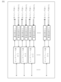
- 2 is an explanatory diagram of the configuration of an interface unit 11, a distribution unit 12, and a multiplexing unit 13 according to the first embodiment.
- 4 is a flowchart of a forwarding process of the frame forwarding device 10 according to the first embodiment.
- 4 is a flowchart of a switch control process according to the first embodiment.
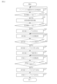
- 6 is a flowchart showing a process of switching the switch 20 in an activated state from the power-saving switch 21 to the high-performance switch 22 according to the first embodiment.
- 4 is an explanatory diagram of a process of switching the switch 20 in an activated state from the power-saving switch 21 to the high-performance switch 22 according to the first embodiment.
- FIG. 1 is a configuration diagram of a frame forwarding device 10 according to a first embodiment.
- 2 is an explanatory diagram of the configuration of an interface unit 11, a distribution unit 12, and a multiplexing unit 13 according to the first embodiment
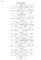
- FIG. 6 is a flowchart showing a process of switching the switch 20 in an activated state from the high-performance switch 22 to the power-saving switch 21 according to the first embodiment.
- 4 is an explanatory diagram of a process of switching the switch 20 in an activated state from the high-performance switch 22 to the power-saving switch 21 according to the first embodiment.
- FIG. FIG. 4 is a state transition diagram of the switch 20 according to the first embodiment.
- FIG. 11 is a configuration diagram of a frame forwarding device 10 according to a second embodiment.
- FIG. 11 is a state transition diagram of the switch 20 according to the second embodiment.
- 13 is a flowchart showing a process of switching the switch 20 in an activated state from the power-saving switch 21 to the high-performance switch 22 according to the third embodiment.
- 13 is a flowchart of a process for switching the switch 20 in an activated state from the high-performance switch 22 to the power-saving switch 21 according to the third embodiment.
- the frame forwarding device 10 is a computer including an interface unit 11 , a distribution unit 12 , a multiplexing unit 13 , a control unit 14 , and a switch 20 consisting of a power-saving switch 21 and a high-performance switch 22 .
- the interface unit 11, the distribution unit 12, the multiplexing unit 13, and the control unit 14 are realized by electronic circuits such as LSIs.
- LSI is an abbreviation for Large-Scale Integration.
- At least a part of the interface unit 11, the distribution unit 12, the multiplexing unit 13, and the control unit 14 may be realized by software.
- the power-saving switch 21 and the high-performance switch 22 are each realized by electronic circuits such as LSIs.
- the power-saving switch 21 and the high-performance switch 22 may each be a device capable of operating independently.
- the switch 20 has a function of transferring communication frames in an order according to a predefined rule or priority order.
- the switch 20 requires a frame buffer to perform sequence control.
- the larger the capacity of the frame buffer the longer it can withstand the process of receiving many communication frames. In other words, the larger the capacity of the frame buffer, the higher the performance.
- the capacity of the frame buffer is large, the amount of power consumed by the frame buffer increases, and the amount of power consumed to control the frame buffer also increases. In other words, the larger the capacity of the frame buffer, the greater the amount of power consumed.
- the high-performance switch 22 is a switch 20 that consumes more power and has higher performance than the power-saving switch 21 .
- the interface unit 11 is a network interface between the frame forwarding device 10 and the external network 90. In other words, the interface unit 11 connects the frame forwarding device 10 to the external network 90.
- the type is not important here.
- the configurations of interface unit 11, distribution unit 12, and multiplexing unit 13 according to the first embodiment will be described with reference to FIG.
- the interface unit 11, the distribution unit 12, and the multiplexing unit 13 are provided corresponding to each of the multiple networks 90.
- Fig. 2 it is assumed that there are n networks 90, from network 90-1 to network 90n.
- the interface unit 11, the distribution unit 12, and the multiplexing unit 13 are provided corresponding to each of the networks 90, from network 90-1 to network 90n.
- a frame received from a network 90 is processed by the corresponding interface unit 11, distribution unit 12, and multiplexing unit 13.
- a frame received from a network 90-1 is processed by the interface unit 11-1, distribution unit 12-1, and multiplexing unit 13-1.
- the operation of the frame forwarding device 10 according to the first embodiment includes forwarding processing and switch control processing.
- the forwarding processing and switch control processing are executed in parallel.
- Step S11 Reception process
- the interface unit 11 receives a communication signal 31, such as an electrical signal or an optical signal for communication, from a network 90.
- the interface unit 11 regenerates a communication frame 32 from the communication signal 31, and inputs the communication frame 32 to the distribution unit 12.
- the interface unit 11 has a function of regenerating the communication frame 32 from the communication signal 31 for each network 90.
- Step S12 Allocation process
- the distribution unit 12 distributes and inputs the communication frame 32 to the power-saving switch 21 or the high-performance switch 22 in accordance with distribution instruction information 34 transmitted from the control unit 14 in the switch control process.
- Step S13 Switch processing
- the power-saving switch 21 or the high-performance switch 22 inputs the input communication frames 32 to the multiplexing unit 13 in an order that follows a predetermined rule or priority order.
- the communication frames 32 are transferred in an order that follows a predetermined rule or priority order.
- Step S14 Multiplexing process
- the multiplexing unit 13 multiplexes the communication frames 32 in order to avoid collisions between the communication frames 32 output by the power-saving switch 21 or the high-performance switch 22 to the interface unit 11 corresponding to the same network 90.
- the multiplexing unit 13 combines the communication frames 32 into one in the input order, and inputs the combined communication frames 32 to the interface unit 11.
- Step S15 Transfer process
- the interface unit 11 converts the communication frame 32 input by the multiplexing unit 13 into a communication signal 31 and outputs it to the network 90 .
- Step S21 Information transmission process
- the allocating unit 12 periodically identifies the flow rate per unit time of the communication frames 32 input from the interface unit 11. Then, the allocating unit 12 transmits traffic status information 33 indicating the identified flow rate to the control unit 14.
- the power-saving switch 21 and the high-performance switch 22 each transmit internal traffic counter information, statistical information such as the number of transfers and the number of discards, frame buffer usage status, MAC learning result information, and the like to the control unit 14 as switch internal information 35. It is an abbreviation for Access Control address.
- the control unit 14 may acquire the switch internal information 35.
- the method of transmitting the switch internal information 35 is in accordance with the function of the switch 20. For example, the method of transmitting the switch internal information 35 is an interrupt process from the switch 20 and a polling process by the control unit 14.
- Step S22 Control process
- the control unit 14 activates one of the power-saving switch 21 and the high-performance switch 22 and deactivates the other switch 20 in accordance with the network load.
- the control unit 14 uses traffic status information 33 and switch internal information 35 to determine which of the power-saving switch 21 and the high-performance switch 22 to activate.
- the control unit 14 activates one of the switches 20 and deactivates the other switch 20 by transmitting a control signal 36 to the power-saving switch 21 and the high-performance switch 22.
- the control unit 14 also transmits distribution instruction information 34 indicating the activated switch 20 as the input destination to the distribution unit 12.
- the control unit 14 activates the power saving switch 21 as an initial state and deactivates the high performance switch 22 .
- the power-saving switch 21 and the high-performance switch 22 each transition between an activated state and an inactivated state under the control of the control unit 14.
- the switch 20 in the activated state is controlled so that a communication frame 32 is input from the distribution unit 12, and the switch 20 in the inactivated state is controlled so that a communication frame 32 is not input from the distribution unit 12.
- step S22 in FIG. 4 The control process (step S22 in FIG. 4) according to the first embodiment will be described with reference to FIG. 5 to FIG.
- the process of switching the switch 20 in the activated state from the power-saving switch 21 to the high-performance switch 22 will be described with reference to FIGS.
- Step S101 Load monitoring process
- the control unit 14 monitors the network load.
- the control unit 14 calculates a predicted load, which is the network load after a reference time, and compares the predicted load with a first threshold value.
- the control unit 14 calculates the predicted utilization rate of the frame buffer of the power saving switch 21 as the predicted load.
- the control unit 14 calculates a change curve of the utilization rate of the frame buffer using the traffic status information 33 and the switch internal information 35 transmitted from the power saving switch 21.
- the control unit 14 identifies the predicted utilization rate after the reference time from the change curve. Then, the control unit 14 compares the predicted utilization rate with a first threshold value.
- the control unit 14 predicts the frame buffer usage rate at each time point from the most recent frame buffer usage status indicated by the switch internal information 35 and the traffic volume expected to be input at each future time point. This identifies an increase/decrease curve of the frame buffer usage rate.
- the control unit 14 predicts the traffic volume expected to be input at each time point from past traffic status information 33.
- the control unit 14 predicts the traffic volume expected to be input at each time point by learning the changes in the flow rate indicated by the past traffic status information 33. This increases the accuracy of the traffic volume prediction as the operation period becomes longer and learning progresses. As a result, the increase/decrease curve of the frame buffer usage rate is also predicted with high accuracy.
- Step S102 First Determination Process
- the control unit 14 determines whether the predicted usage rate is higher than a first threshold value. If the predicted usage rate is higher than the first threshold, the control unit 14 advances the process to step S103. On the other hand, if the predicted usage rate is not higher than the first threshold, the control unit 14 returns the process to step S101.
- Step S103 Standby process
- the control unit 14 waits until a switching determination period has elapsed from the first confirmation time point at which the determination in step S102 was made.
- the switching determination period is set in advance.
- Step S104 Second Determination Process
- the control unit 14 determines whether the predicted usage rate is higher than a first threshold value. If the predicted usage rate is higher than the first threshold, the control unit 14 advances the process to step S105. On the other hand, if the predicted usage rate is not higher than the first threshold, the control unit 14 returns the process to step S101.
- Step S105 Activation process
- the control unit 14 transmits a control signal 36 to activate the high-performance switch 22.
- a cold boot is to start up the high-performance switch 22 after supplying power to it.
- a warm boot is to release the stopped state of the high-performance switch 22.
- the stopped state is either a sleep state or a suspended state.
- the control unit 14 sets information required for forwarding the communication frame 32, such as the MAC learning result updated by the power-saving switch 21 while the high-performance switch 22 is in an inactive state, in the high-performance switch 22.
- the MAC learning result is information included in the switch internal information 35. This causes the state of the high-performance switch 22 to be synchronized with the state of the power-saving switch 21.
- Step S106 Status monitoring process
- the control unit 14 monitors the state of the high-performance switch 22. For example, information on the state of the high-performance switch 22 is obtained by an interrupt process from the high-performance switch 22 or a polling process by the control unit 14.
- Step S107 State determination process
- the control unit 14 determines whether or not the high-performance switch 22 has completed the transition from the inactive state to the active state. If the transition is complete and the stable operation has been entered, the control unit 14 advances the process to step S108. On the other hand, if the transition is not complete and the stable operation has not been entered, the control unit 14 returns the process to step S106.
- Step S108 Allocation instruction process
- the control unit 14 transmits distribution instruction information 34 indicating the high-performance switch 22 as an input destination to the distribution unit 12. That is, when the high-performance switch 22 completes the transition to the active state and enters stable operation, the control unit 14 instructs the distribution unit 12 to set the high-performance switch 22 as the input destination. That is, the control unit 14 maintains the state in which the power-saving switch 21 is set as the input destination until the high-performance switch 22 completes the transition to the active state and enters stable operation.
- Step S109 Usage monitoring process
- the control unit 14 monitors the frame buffer usage status included in the switch internal information 35 transmitted from the power saving switch 21 .
- Step S110 Use determination process
- the control unit 14 judges whether or not the frame buffer usage rate of the power saving switch 21 has become zero. When the frame buffer usage rate has become zero, this means that the power saving switch 21 is no longer outputting frames. If the frame buffer usage rate has become zero, the control unit 14 advances the process to step S111. On the other hand, if the frame buffer usage rate has not become zero, the control unit 14 returns the process to step S109.
- Step S111 Inactivation treatment
- the control unit 14 transmits a control signal 36 to deactivate the power saving switch 21. If the activation is a cold boot in step S205 described later, the deactivation is to shut down the power saving switch 21 and then cut off the power supply. If the activation is a warm boot in step S205 described later, the deactivation is to put the power saving switch 21 into a stopped state.
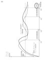
- the control unit 14 determines whether the predicted load at the first confirmation time point is higher than the first threshold value, and whether the predicted load at the second confirmation time point, which is the switching judgment period after the first confirmation time point, is higher than the first threshold value. 6, the predicted load is higher than the first threshold at time T11. However, at time T12, which is a switching determination period after time T11, the predicted load is lower than the first threshold. Therefore, in this case, the control unit 14 does not determine to activate the high-performance switch 22, and keeps the power-saving switch 21 in the activated state. 6, the predicted load is higher than the first threshold value at time T13. Also, at time T14, which is a switching determination period after time T13, the predicted load is higher than the first threshold value. Therefore, in this case, at time T14, the control unit 14 determines to activate the high-performance switch 22.
- the first threshold is determined based on the configuration of the network to which it is applied, generally expected traffic fluctuation information such as during busy periods, and statistical information on traffic fluctuations learned by the frame forwarding device 10.
- the first threshold is set in advance, or an optimal value is automatically reflected according to the learning results.
- the first threshold is set to a value that takes into account that the power-saving switch 21 is selected during the time from the activation process of the high-performance switch 22 to the transition to stable operation.
- Step S201 Load monitoring process
- the control unit 14 monitors the network load.
- the control unit 14 calculates a predicted load, which is the network load after a reference time, and compares the predicted load with a second threshold value.
- the control unit 14 calculates the predicted utilization rate of the frame buffer of the high-performance switch 22 as the predicted load.
- the control unit 14 calculates a change curve of the utilization rate of the frame buffer using the traffic status information 33 and the switch internal information 35 transmitted from the high-performance switch 22.
- the control unit 14 identifies the predicted utilization rate after the reference time from the change curve. Then, the control unit 14 compares the predicted utilization rate with a second threshold value.
- Step S202 First Determination Process
- the control unit 14 determines whether the predicted usage rate is lower than a second threshold value. If the predicted usage rate is lower than the second threshold, the control unit 14 advances the process to step S203. On the other hand, if the predicted usage rate is not lower than the second threshold, the control unit 14 returns the process to step S201.
- Step S203 Standby process
- the control unit 14 waits until the switching determination period has elapsed from the first confirmation time point at which the determination in step S202 was made.
- Step S204 Second Determination Process
- the control unit 14 determines whether the predicted usage rate is lower than a second threshold value. If the predicted usage rate is lower than the second threshold, the control unit 14 advances the process to step S205. On the other hand, if the predicted usage rate is not lower than the second threshold, the control unit 14 returns the process to step S201.
- Step S205 Activation process
- the control unit 14 transmits a control signal 36 to activate the power saving switch 21.
- a cold boot is to start up the power saving switch 21 after supplying power to it.
- a warm boot is to release the power saving switch 21 from a stopped state.
- the control unit 14 sets, in the high-performance switch 22, information required for transferring the communication frame 32, such as the MAC learning result updated by the high-performance switch 22 while the power-saving switch 21 is in the inactive state. In this way, the state of the power-saving switch 21 is synchronized with the state of the high-performance switch 22.
- Step S206 Status monitoring process
- the control unit 14 monitors the state of the power saving switch 21. For example, information on the state of the power saving switch 21 is obtained by an interrupt process from the power saving switch 21 or a polling process by the control unit 14.
- Step S207 State determination process
- the control unit 14 determines whether or not the power saving switch 21 has completed transition from the inactive state to the active state. If the transition is complete and the stable operation has started, the control unit 14 advances the process to step S208. On the other hand, if the transition is not complete and the stable operation has not started, the control unit 14 returns the process to step S206.
- Step S208 Allocation instruction process
- the control unit 14 transmits distribution instruction information 34 indicating the power-saving switch 21 as an input destination to the distribution unit 12. That is, when the power-saving switch 21 completes the transition to the active state and enters stable operation, the control unit 14 instructs the distribution unit 12 to set the power-saving switch 21 as the input destination. That is, the control unit 14 maintains the state in which the high-performance switch 22 is the input destination until the power-saving switch 21 completes the transition to the active state and enters stable operation.
- Step S209 Usage monitoring process
- the control unit 14 monitors the frame buffer usage status included in the switch internal information 35 transmitted from the high-performance switch 22 .
- Step S210 Use determination process
- the control unit 14 judges whether or not the frame buffer usage rate of the high-performance switch 22 has become zero. When the frame buffer usage rate has become zero, this means that the high-performance switch 22 is no longer outputting frames. If the frame buffer usage rate has become zero, the control unit 14 advances the process to step S211. On the other hand, if the frame buffer usage rate has not become zero, the control unit 14 returns the process to step S209.
- Step S211 Inactivation treatment
- the control unit 14 transmits the control signal 36 to deactivate the high-performance switch 22. If the activation in the above-mentioned step S105 is a cold boot, the deactivation is to shut down the high-performance switch 22 and then cut off the power supply. If the activation in the above-mentioned step S105 is a warm boot, the deactivation is to put the high-performance switch 22 in a stopped state.
- the control unit 14 determines whether the predicted load at the first confirmation time point is lower than the second threshold value, and whether the predicted load at the second confirmation time point which is the switching judgment period after the first confirmation time point is lower than the second threshold value. 8, the predicted load is lower than the second threshold. However, at time T22, which is a switching determination period after time T21, the predicted load is higher than the second threshold. Therefore, in this case, the control unit 14 does not determine to activate the power-saving switch 21, and keeps the high-performance switch 22 in the activated state. 8, the predicted load is lower than the second threshold. Also, at time T24, which is a switching determination period after time T23, the predicted load is lower than the second threshold. Therefore, in this case, at time T24, the control unit 14 determines to activate the power saving switch 21.
- the second threshold is determined based on the configuration of the network to which it is applied, generally expected traffic fluctuation information such as during busy periods, and statistical information on traffic fluctuations learned by the frame forwarding device 10.
- the second threshold is set in advance, or an optimal value is automatically reflected according to the learning results.
- the second threshold is set with a margin, taking into account the frame buffer size of the power saving switch 21, so that the switch 20 to be activated is not repeatedly switched at short intervals.
- the state transition of the switch 20 according to the first embodiment will be described with reference to FIG.
- the frame forwarding device 10 is started.
- the power-saving switch 21 is maintained in an activated state (S301), and when it is determined that the performance of the power-saving switch 21 is not sufficient for processing due to an increase in the communication load, the high-performance switch 22 is activated (S302).
- the power-saving switch 21 is deactivated, and only the high-performance switch 22 is maintained in an activated state (S303).
- the power-saving switch 21 is activated (S304).
- the power-saving switch 21 is in a stable operation state, the high-performance switch 22 is deactivated, and only the power-saving switch 21 is maintained in an activated state (S301).
- the input amount on the input side which is the frame multiplexing target
- the output amount on the output side which is the frame multiplexing result.
- the transient state occurs during the following periods (1) and (2).
- Period (1) is the period from when the high-performance switch 22 is selected as the input destination in step S108 of FIG.
- the multiplexing unit 13 includes a frame buffer.
- the multiplexing unit 13 receives the communication frames 32 output from the power-saving switch 21 and the high-performance switch 22. are temporarily stored in a frame buffer, and then multiplexed in order and input to the interface unit 11. This makes it possible to multiplex communication frames 32 without dropping any of them, even if the input amount exceeds the output amount.
- the frame forwarding device 10 activates one of the switches 20 in response to the network load and deactivates the other switch 20. This makes it possible to achieve power saving for the frame forwarding device 10 as a whole.
- the frame forwarding device 10 performs a comparison with the threshold not only at the first confirmation time point, but also at the second confirmation time point, which is a switching decision period after the first confirmation time point, to determine whether or not to switch the switch 20 to be activated. This prevents the switch 20 to be activated from being switched repeatedly within a short period of time. As a result, power consumption associated with switching can be reduced.
- Embodiment 2 differs from the first embodiment in that there are three or more types of switches 20. In the second embodiment, this difference will be described, and a description of the same points will be omitted.
- the frame forwarding device 10 includes the switches 20 having two types of performance: a power-saving switch 21 and a high-performance switch 22.
- the frame forwarding device 10 may include the switches 20 having three or more types of performance.
- the frame forwarding device 10 may include a medium-performance switch 23 as the switch 20 in addition to a power-saving switch 21 and a high-performance switch 22.
- the medium-performance switch 23 is a switch 20 that consumes more power and has higher performance than the power-saving switch 21 and consumes less power and has lower performance than the high-performance switch 22.
- the state transition of the switch 20 according to the second embodiment will be described with reference to FIG.
- the frame forwarding device 10 is started. Then, the power-saving switch 21 is maintained in an activated state (S401), and when it is determined that the performance of the power-saving switch 21 is insufficient for processing due to an increase in the communication load, the medium-performance switch 23 is first activated (S402). After the medium-performance switch 23 has stabilized, the power-saving switch 21 is deactivated, and only the medium-performance switch 23 is maintained in an activated state (S403). When the communication load further increases and it is determined that the performance of the medium-performance switch 23 is insufficient for processing, the high-performance switch 22 is activated (S404).
- the medium-performance switch 23 is deactivated, and only the high-performance switch 22 is maintained in an activated state (S405).
- the power-saving switch 21 is activated (S408).
- the medium-performance switch 23 is deactivated and only the power-saving switch 21 is maintained in the activated state (S401).
- the communication load decreases from the state of S405 and it is determined that processing is possible with the performance of the medium performance switch 23 is activated (S406).
- the high performance switch 22 is deactivated and only the medium performance switch 23 is maintained in an activated state (S407).
- S407 transitions to S404 if the communication load increases, and transitions to S401 if the communication load decreases.
- the frame forwarding device 10 includes three or more types of switches 2. In this case as well, one switch 20 is activated while the other switches 20 are deactivated in accordance with the network load. This makes it possible to achieve power saving in the frame forwarding device 10 as a whole.
- Embodiment 3 differs from the first and second embodiments in that the multiplexing unit 13 does not have a frame buffer for frame multiplexing. In the third embodiment, this difference will be described, and a description of the same points will be omitted. In the third embodiment, a case where a modification is made to the first embodiment will be described. However, it is also possible to make a modification to the second embodiment.
- the frame buffer of the multiplexing unit 13 is omitted, and the switch 20 is switched in a procedure that prevents frame dropout during frame multiplexing in the switch control process.
- steps S501 to S507 are the same as the processes from steps S101 to S107 in FIG. 5.
- Step S508 Output Prohibition Setting Process
- step S509 to step S511 is the same as the processing from step S108 to step S110 in FIG. 5.
- Step S512 Output permission setting process
- step S513 is the same as the processing in step S111 in FIG. 5.
- steps S601 to S607 are the same as the processes from steps S201 to S207 in FIG. 7.
- Step S608 Output Prohibition Setting Process
- step S609 to step S611 is the same as the processing from step S208 to step S210 in FIG. 7.
- Step S612 Output permission setting process
- the control unit 14 releases the output prohibition setting that was temporarily set for the power-saving switch 21.
- the control unit 14 opens the output port of the power-saving switch 21.
- the power saving switch 21 starts outputting the frames stored in the frame buffer to the multiplexer 13 .
- step S613 is the same as the processing in step S211 in FIG. 7.
- the communication frames 32 from the power-saving switch 21 and the high-performance switch 22 are not input to the multiplexing unit 13 at the same time. Therefore, the maximum input speed does not exceed the output speed, and a frame buffer for multiplexing the communication frames 32 is not required. As a result, it is possible to realize reduced functionality, scale, and power consumption in the multiplexing unit 13 and, in turn, in the frame forwarding device 10.
- circuit In addition, the word "part” in the above explanation may be interpreted as “circuit,” “process,” “procedure,” “processing,” or “processing circuit.”
- 10 Frame forwarding device 11 Interface unit, 12 Distribution unit, 13 Multiplexing unit, 14 Control unit, 20 Switch, 21 Power saving switch, 22 High performance switch, 23 Medium performance switch, 31 Communication signal, 32 Communication frame, 33 Traffic status information, 34 Distribution instruction information, 35 Switch internal information, 36 Control signal, 90 Network.
Landscapes
- Engineering & Computer Science (AREA)
- Computer Networks & Wireless Communication (AREA)
- Signal Processing (AREA)
- Small-Scale Networks (AREA)
Abstract
Un dispositif de transfert de trame (10) comprend des commutateurs (20) constitués d'un commutateur d'économie d'énergie (21) et un commutateur haute performance (22) ayant une consommation d'énergie supérieure et une performance supérieure à celle du commutateur d'économie d'énergie (21). Une unité de commande (14) active un commutateur (20) parmi le commutateur d'économie d'énergie (21) et le commutateur haute performance (22) et désactive l'autre commutateur (20) selon une charge de réseau. Une unité de distribution (12) distribue une trame reçue au commutateur (20) activé par l'unité de commande (14).
Priority Applications (3)
| Application Number | Priority Date | Filing Date | Title |
|---|---|---|---|
| CN202480035693.XA CN121241543A (zh) | 2023-06-05 | 2024-04-02 | 帧传送装置、控制方法以及控制程序 |
| JP2025525958A JP7714157B2 (ja) | 2023-06-05 | 2024-04-02 | フレーム転送装置、制御方法及び制御プログラム |
| US19/357,249 US20260039550A1 (en) | 2023-06-05 | 2025-10-14 | Frame transfer device, control method, and computer readable medium |
Applications Claiming Priority (2)
| Application Number | Priority Date | Filing Date | Title |
|---|---|---|---|
| PCT/JP2023/020851 WO2024252484A1 (fr) | 2023-06-05 | 2023-06-05 | Dispositif de transfert de trame, procédé de commande et programme de commande |
| JPPCT/JP2023/020851 | 2023-06-05 |
Related Child Applications (1)
| Application Number | Title | Priority Date | Filing Date |
|---|---|---|---|
| US19/357,249 Continuation US20260039550A1 (en) | 2023-06-05 | 2025-10-14 | Frame transfer device, control method, and computer readable medium |
Publications (1)
| Publication Number | Publication Date |
|---|---|
| WO2024252768A1 true WO2024252768A1 (fr) | 2024-12-12 |
Family
ID=93795139
Family Applications (2)
| Application Number | Title | Priority Date | Filing Date |
|---|---|---|---|
| PCT/JP2023/020851 Ceased WO2024252484A1 (fr) | 2023-06-05 | 2023-06-05 | Dispositif de transfert de trame, procédé de commande et programme de commande |
| PCT/JP2024/013538 Ceased WO2024252768A1 (fr) | 2023-06-05 | 2024-04-02 | Dispositif de transfert de trame, procédé de commande et programme de commande |
Family Applications Before (1)
| Application Number | Title | Priority Date | Filing Date |
|---|---|---|---|
| PCT/JP2023/020851 Ceased WO2024252484A1 (fr) | 2023-06-05 | 2023-06-05 | Dispositif de transfert de trame, procédé de commande et programme de commande |
Country Status (4)
| Country | Link |
|---|---|
| US (1) | US20260039550A1 (fr) |
| JP (1) | JP7714157B2 (fr) |
| CN (1) | CN121241543A (fr) |
| WO (2) | WO2024252484A1 (fr) |
Citations (4)
| Publication number | Priority date | Publication date | Assignee | Title |
|---|---|---|---|---|
| JP2000083062A (ja) * | 1998-06-30 | 2000-03-21 | Hitachi Ltd | パケット転送方法およびパケット処理装置 |
| JP2009033691A (ja) * | 2007-06-25 | 2009-02-12 | Alaxala Networks Corp | ネットワーク装置の消費電力低減制御装置及び制御方法 |
| JP2012120085A (ja) * | 2010-12-03 | 2012-06-21 | Mitsubishi Electric Corp | ネットワーク中継装置および中継方法 |
| JP2014135533A (ja) * | 2013-01-08 | 2014-07-24 | Hitachi Ltd | ネットワーク装置、性能制御方法及びネットワークシステム |
-
2023
- 2023-06-05 WO PCT/JP2023/020851 patent/WO2024252484A1/fr not_active Ceased
-
2024
- 2024-04-02 JP JP2025525958A patent/JP7714157B2/ja active Active
- 2024-04-02 CN CN202480035693.XA patent/CN121241543A/zh active Pending
- 2024-04-02 WO PCT/JP2024/013538 patent/WO2024252768A1/fr not_active Ceased
-
2025
- 2025-10-14 US US19/357,249 patent/US20260039550A1/en active Pending
Patent Citations (4)
| Publication number | Priority date | Publication date | Assignee | Title |
|---|---|---|---|---|
| JP2000083062A (ja) * | 1998-06-30 | 2000-03-21 | Hitachi Ltd | パケット転送方法およびパケット処理装置 |
| JP2009033691A (ja) * | 2007-06-25 | 2009-02-12 | Alaxala Networks Corp | ネットワーク装置の消費電力低減制御装置及び制御方法 |
| JP2012120085A (ja) * | 2010-12-03 | 2012-06-21 | Mitsubishi Electric Corp | ネットワーク中継装置および中継方法 |
| JP2014135533A (ja) * | 2013-01-08 | 2014-07-24 | Hitachi Ltd | ネットワーク装置、性能制御方法及びネットワークシステム |
Also Published As
| Publication number | Publication date |
|---|---|
| WO2024252484A1 (fr) | 2024-12-12 |
| JPWO2024252768A1 (fr) | 2024-12-12 |
| US20260039550A1 (en) | 2026-02-05 |
| CN121241543A (zh) | 2025-12-30 |
| JP7714157B2 (ja) | 2025-07-28 |
Similar Documents
| Publication | Publication Date | Title |
|---|---|---|
| US7804794B2 (en) | Power-saving network switching device | |
| CN102415009B (zh) | 数据接口能耗控制 | |
| EP2340623B1 (fr) | Gestion de puissance d'un dispositif de réseau | |
| JP2004246894A (ja) | ネットワーク・プロセッサの省電力方法及び装置 | |
| JP4903276B2 (ja) | Ieee802標準のネットワークにおけるパワー・セービング | |
| EP2354891B1 (fr) | Appareil de traitement d'informations et son procédé de contrôle | |
| EP2351454A1 (fr) | Solution phy provisoire pour une compatibilité lpi avec des dispositifs existants | |
| WO2010050041A1 (fr) | Système d'ordinateur | |
| WO2011120879A1 (fr) | Procédé permettant de réduire la consommation d'énergie dans des cartes de lignes de traitement de paquets | |
| JP2013176041A (ja) | 複数のトラフィッククラスを含むパケット交換ネットワークにおけるトラフィックシェーピングの方法及び装置 | |
| WO2023165419A1 (fr) | Procédé et appareil de commande du sommeil d'un dispositif de réseau, et dispositif de réseau et support d'enregistrement | |
| EP4239453A1 (fr) | Procédé et appareil de gestion de puce de réseau, dispositif de communication et support de stockage | |
| JP7714157B2 (ja) | フレーム転送装置、制御方法及び制御プログラム | |
| JP2011087024A (ja) | ネットワーク管理装置 | |
| CN120302392A (zh) | 一种基于ZIGBEE的Wi-Fi模组的休眠方法 | |
| JP2009037285A (ja) | ネットワーク装置 | |
| JP6248469B2 (ja) | 通信方法、通信システム、及び通信装置 | |
| JP4825740B2 (ja) | 電力制御装置および方法 | |
| JP2006331107A (ja) | 電力管理回路、及び電子回路 | |
| JP2010103655A (ja) | ネットワーク接続装置 | |
| JP3362127B2 (ja) | 省電力モード制御システム、サーバマシーン | |
| JP2010183470A (ja) | ネットワーク接続装置並びにネットワーク接続制御方法及びプログラム | |
| EP3066785B1 (fr) | Gestion de mode de fonctionnement inactif dans des commutateurs réseau | |
| EP3563519B1 (fr) | Technologies pour un protocole de gestion de puissance de réseau local | |
| JP2014103439A (ja) | 通信装置、通信システム、通信装置の制御方法及び通信装置の制御プログラム |
Legal Events
| Date | Code | Title | Description |
|---|---|---|---|
| 121 | Ep: the epo has been informed by wipo that ep was designated in this application |
Ref document number: 24819007 Country of ref document: EP Kind code of ref document: A1 |
|
| WWE | Wipo information: entry into national phase |
Ref document number: 2025525958 Country of ref document: JP |
|
| NENP | Non-entry into the national phase |
Ref country code: DE |