WO2024252768A1 - フレーム転送装置、制御方法及び制御プログラム - Google Patents
フレーム転送装置、制御方法及び制御プログラム Download PDFInfo
- Publication number
- WO2024252768A1 WO2024252768A1 PCT/JP2024/013538 JP2024013538W WO2024252768A1 WO 2024252768 A1 WO2024252768 A1 WO 2024252768A1 JP 2024013538 W JP2024013538 W JP 2024013538W WO 2024252768 A1 WO2024252768 A1 WO 2024252768A1
- Authority
- WO
- WIPO (PCT)
- Prior art keywords
- switch
- power
- performance
- control unit
- saving
- Prior art date
- Legal status (The legal status is an assumption and is not a legal conclusion. Google has not performed a legal analysis and makes no representation as to the accuracy of the status listed.)
- Ceased
Links
Images





Classifications
-
- H—ELECTRICITY
- H04—ELECTRIC COMMUNICATION TECHNIQUE
- H04L—TRANSMISSION OF DIGITAL INFORMATION, e.g. TELEGRAPHIC COMMUNICATION
- H04L41/00—Arrangements for maintenance, administration or management of data switching networks, e.g. of packet switching networks
- H04L41/08—Configuration management of networks or network elements
- H04L41/0803—Configuration setting
- H04L41/0823—Configuration setting characterised by the purposes of a change of settings, e.g. optimising configuration for enhancing reliability
- H04L41/0833—Configuration setting characterised by the purposes of a change of settings, e.g. optimising configuration for enhancing reliability for reduction of network energy consumption
-
- H—ELECTRICITY
- H04—ELECTRIC COMMUNICATION TECHNIQUE
- H04L—TRANSMISSION OF DIGITAL INFORMATION, e.g. TELEGRAPHIC COMMUNICATION
- H04L12/00—Data switching networks
- H04L12/28—Data switching networks characterised by path configuration, e.g. LAN [Local Area Networks] or WAN [Wide Area Networks]
- H04L12/40—Bus networks
-
- H—ELECTRICITY
- H04—ELECTRIC COMMUNICATION TECHNIQUE
- H04L—TRANSMISSION OF DIGITAL INFORMATION, e.g. TELEGRAPHIC COMMUNICATION
- H04L41/00—Arrangements for maintenance, administration or management of data switching networks, e.g. of packet switching networks
- H04L41/14—Network analysis or design
- H04L41/147—Network analysis or design for predicting network behaviour
-
- H—ELECTRICITY
- H04—ELECTRIC COMMUNICATION TECHNIQUE
- H04L—TRANSMISSION OF DIGITAL INFORMATION, e.g. TELEGRAPHIC COMMUNICATION
- H04L49/00—Packet switching elements
- H04L49/10—Packet switching elements characterised by the switching fabric construction
Definitions
- This disclosure relates to power saving in frame forwarding devices.
- Patent Document 1 describes how a communication device is equipped with multiple packet processing circuits with different processing capabilities, and the most suitable processing circuit is selected and used for the amount of data input within a certain period of time.
- the multiple packet processing circuits with different processing capabilities are, for example, a high-speed circuit, a medium-speed circuit, and a low-speed circuit.
- An object of the present disclosure is to make it possible to realize power saving in a frame forwarding device.
- a frame forwarding device includes: a power-saving switch and a high-performance switch that consumes more power and has higher performance than the power-saving switch; a control unit that activates one of the power-saving switch and the high-performance switch and deactivates the other switch according to a network load; and a distribution unit that distributes received frames to the switches activated by the control unit.
- one switch is activated and the other switch is deactivated depending on the network load. By deactivating the other switch, it is possible to achieve power savings for the entire frame forwarding device.
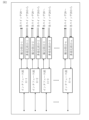
- FIG. 1 is a configuration diagram of a frame forwarding device 10 according to a first embodiment.
- 2 is an explanatory diagram of the configuration of an interface unit 11, a distribution unit 12, and a multiplexing unit 13 according to the first embodiment.
- 4 is a flowchart of a forwarding process of the frame forwarding device 10 according to the first embodiment.
- 4 is a flowchart of a switch control process according to the first embodiment.
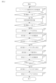
- 6 is a flowchart showing a process of switching the switch 20 in an activated state from the power-saving switch 21 to the high-performance switch 22 according to the first embodiment.
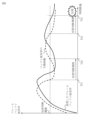
- 4 is an explanatory diagram of a process of switching the switch 20 in an activated state from the power-saving switch 21 to the high-performance switch 22 according to the first embodiment.
- FIG. 1 is a configuration diagram of a frame forwarding device 10 according to a first embodiment.
- 2 is an explanatory diagram of the configuration of an interface unit 11, a distribution unit 12, and a multiplexing unit 13 according to the first embodiment
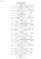
- FIG. 6 is a flowchart showing a process of switching the switch 20 in an activated state from the high-performance switch 22 to the power-saving switch 21 according to the first embodiment.
- 4 is an explanatory diagram of a process of switching the switch 20 in an activated state from the high-performance switch 22 to the power-saving switch 21 according to the first embodiment.
- FIG. FIG. 4 is a state transition diagram of the switch 20 according to the first embodiment.
- FIG. 11 is a configuration diagram of a frame forwarding device 10 according to a second embodiment.
- FIG. 11 is a state transition diagram of the switch 20 according to the second embodiment.
- 13 is a flowchart showing a process of switching the switch 20 in an activated state from the power-saving switch 21 to the high-performance switch 22 according to the third embodiment.
- 13 is a flowchart of a process for switching the switch 20 in an activated state from the high-performance switch 22 to the power-saving switch 21 according to the third embodiment.
- the frame forwarding device 10 is a computer including an interface unit 11 , a distribution unit 12 , a multiplexing unit 13 , a control unit 14 , and a switch 20 consisting of a power-saving switch 21 and a high-performance switch 22 .
- the interface unit 11, the distribution unit 12, the multiplexing unit 13, and the control unit 14 are realized by electronic circuits such as LSIs.
- LSI is an abbreviation for Large-Scale Integration.
- At least a part of the interface unit 11, the distribution unit 12, the multiplexing unit 13, and the control unit 14 may be realized by software.
- the power-saving switch 21 and the high-performance switch 22 are each realized by electronic circuits such as LSIs.
- the power-saving switch 21 and the high-performance switch 22 may each be a device capable of operating independently.
- the switch 20 has a function of transferring communication frames in an order according to a predefined rule or priority order.
- the switch 20 requires a frame buffer to perform sequence control.
- the larger the capacity of the frame buffer the longer it can withstand the process of receiving many communication frames. In other words, the larger the capacity of the frame buffer, the higher the performance.
- the capacity of the frame buffer is large, the amount of power consumed by the frame buffer increases, and the amount of power consumed to control the frame buffer also increases. In other words, the larger the capacity of the frame buffer, the greater the amount of power consumed.
- the high-performance switch 22 is a switch 20 that consumes more power and has higher performance than the power-saving switch 21 .
- the interface unit 11 is a network interface between the frame forwarding device 10 and the external network 90. In other words, the interface unit 11 connects the frame forwarding device 10 to the external network 90.
- the type is not important here.
- the configurations of interface unit 11, distribution unit 12, and multiplexing unit 13 according to the first embodiment will be described with reference to FIG.
- the interface unit 11, the distribution unit 12, and the multiplexing unit 13 are provided corresponding to each of the multiple networks 90.
- Fig. 2 it is assumed that there are n networks 90, from network 90-1 to network 90n.
- the interface unit 11, the distribution unit 12, and the multiplexing unit 13 are provided corresponding to each of the networks 90, from network 90-1 to network 90n.
- a frame received from a network 90 is processed by the corresponding interface unit 11, distribution unit 12, and multiplexing unit 13.
- a frame received from a network 90-1 is processed by the interface unit 11-1, distribution unit 12-1, and multiplexing unit 13-1.
- the operation of the frame forwarding device 10 according to the first embodiment includes forwarding processing and switch control processing.
- the forwarding processing and switch control processing are executed in parallel.
- Step S11 Reception process
- the interface unit 11 receives a communication signal 31, such as an electrical signal or an optical signal for communication, from a network 90.
- the interface unit 11 regenerates a communication frame 32 from the communication signal 31, and inputs the communication frame 32 to the distribution unit 12.
- the interface unit 11 has a function of regenerating the communication frame 32 from the communication signal 31 for each network 90.
- Step S12 Allocation process
- the distribution unit 12 distributes and inputs the communication frame 32 to the power-saving switch 21 or the high-performance switch 22 in accordance with distribution instruction information 34 transmitted from the control unit 14 in the switch control process.
- Step S13 Switch processing
- the power-saving switch 21 or the high-performance switch 22 inputs the input communication frames 32 to the multiplexing unit 13 in an order that follows a predetermined rule or priority order.
- the communication frames 32 are transferred in an order that follows a predetermined rule or priority order.
- Step S14 Multiplexing process
- the multiplexing unit 13 multiplexes the communication frames 32 in order to avoid collisions between the communication frames 32 output by the power-saving switch 21 or the high-performance switch 22 to the interface unit 11 corresponding to the same network 90.
- the multiplexing unit 13 combines the communication frames 32 into one in the input order, and inputs the combined communication frames 32 to the interface unit 11.
- Step S15 Transfer process
- the interface unit 11 converts the communication frame 32 input by the multiplexing unit 13 into a communication signal 31 and outputs it to the network 90 .
- Step S21 Information transmission process
- the allocating unit 12 periodically identifies the flow rate per unit time of the communication frames 32 input from the interface unit 11. Then, the allocating unit 12 transmits traffic status information 33 indicating the identified flow rate to the control unit 14.
- the power-saving switch 21 and the high-performance switch 22 each transmit internal traffic counter information, statistical information such as the number of transfers and the number of discards, frame buffer usage status, MAC learning result information, and the like to the control unit 14 as switch internal information 35. It is an abbreviation for Access Control address.
- the control unit 14 may acquire the switch internal information 35.
- the method of transmitting the switch internal information 35 is in accordance with the function of the switch 20. For example, the method of transmitting the switch internal information 35 is an interrupt process from the switch 20 and a polling process by the control unit 14.
- Step S22 Control process
- the control unit 14 activates one of the power-saving switch 21 and the high-performance switch 22 and deactivates the other switch 20 in accordance with the network load.
- the control unit 14 uses traffic status information 33 and switch internal information 35 to determine which of the power-saving switch 21 and the high-performance switch 22 to activate.
- the control unit 14 activates one of the switches 20 and deactivates the other switch 20 by transmitting a control signal 36 to the power-saving switch 21 and the high-performance switch 22.
- the control unit 14 also transmits distribution instruction information 34 indicating the activated switch 20 as the input destination to the distribution unit 12.
- the control unit 14 activates the power saving switch 21 as an initial state and deactivates the high performance switch 22 .
- the power-saving switch 21 and the high-performance switch 22 each transition between an activated state and an inactivated state under the control of the control unit 14.
- the switch 20 in the activated state is controlled so that a communication frame 32 is input from the distribution unit 12, and the switch 20 in the inactivated state is controlled so that a communication frame 32 is not input from the distribution unit 12.
- step S22 in FIG. 4 The control process (step S22 in FIG. 4) according to the first embodiment will be described with reference to FIG. 5 to FIG.
- the process of switching the switch 20 in the activated state from the power-saving switch 21 to the high-performance switch 22 will be described with reference to FIGS.
- Step S101 Load monitoring process
- the control unit 14 monitors the network load.
- the control unit 14 calculates a predicted load, which is the network load after a reference time, and compares the predicted load with a first threshold value.
- the control unit 14 calculates the predicted utilization rate of the frame buffer of the power saving switch 21 as the predicted load.
- the control unit 14 calculates a change curve of the utilization rate of the frame buffer using the traffic status information 33 and the switch internal information 35 transmitted from the power saving switch 21.
- the control unit 14 identifies the predicted utilization rate after the reference time from the change curve. Then, the control unit 14 compares the predicted utilization rate with a first threshold value.
- the control unit 14 predicts the frame buffer usage rate at each time point from the most recent frame buffer usage status indicated by the switch internal information 35 and the traffic volume expected to be input at each future time point. This identifies an increase/decrease curve of the frame buffer usage rate.
- the control unit 14 predicts the traffic volume expected to be input at each time point from past traffic status information 33.
- the control unit 14 predicts the traffic volume expected to be input at each time point by learning the changes in the flow rate indicated by the past traffic status information 33. This increases the accuracy of the traffic volume prediction as the operation period becomes longer and learning progresses. As a result, the increase/decrease curve of the frame buffer usage rate is also predicted with high accuracy.
- Step S102 First Determination Process
- the control unit 14 determines whether the predicted usage rate is higher than a first threshold value. If the predicted usage rate is higher than the first threshold, the control unit 14 advances the process to step S103. On the other hand, if the predicted usage rate is not higher than the first threshold, the control unit 14 returns the process to step S101.
- Step S103 Standby process
- the control unit 14 waits until a switching determination period has elapsed from the first confirmation time point at which the determination in step S102 was made.
- the switching determination period is set in advance.
- Step S104 Second Determination Process
- the control unit 14 determines whether the predicted usage rate is higher than a first threshold value. If the predicted usage rate is higher than the first threshold, the control unit 14 advances the process to step S105. On the other hand, if the predicted usage rate is not higher than the first threshold, the control unit 14 returns the process to step S101.
- Step S105 Activation process
- the control unit 14 transmits a control signal 36 to activate the high-performance switch 22.
- a cold boot is to start up the high-performance switch 22 after supplying power to it.
- a warm boot is to release the stopped state of the high-performance switch 22.
- the stopped state is either a sleep state or a suspended state.
- the control unit 14 sets information required for forwarding the communication frame 32, such as the MAC learning result updated by the power-saving switch 21 while the high-performance switch 22 is in an inactive state, in the high-performance switch 22.
- the MAC learning result is information included in the switch internal information 35. This causes the state of the high-performance switch 22 to be synchronized with the state of the power-saving switch 21.
- Step S106 Status monitoring process
- the control unit 14 monitors the state of the high-performance switch 22. For example, information on the state of the high-performance switch 22 is obtained by an interrupt process from the high-performance switch 22 or a polling process by the control unit 14.
- Step S107 State determination process
- the control unit 14 determines whether or not the high-performance switch 22 has completed the transition from the inactive state to the active state. If the transition is complete and the stable operation has been entered, the control unit 14 advances the process to step S108. On the other hand, if the transition is not complete and the stable operation has not been entered, the control unit 14 returns the process to step S106.
- Step S108 Allocation instruction process
- the control unit 14 transmits distribution instruction information 34 indicating the high-performance switch 22 as an input destination to the distribution unit 12. That is, when the high-performance switch 22 completes the transition to the active state and enters stable operation, the control unit 14 instructs the distribution unit 12 to set the high-performance switch 22 as the input destination. That is, the control unit 14 maintains the state in which the power-saving switch 21 is set as the input destination until the high-performance switch 22 completes the transition to the active state and enters stable operation.
- Step S109 Usage monitoring process
- the control unit 14 monitors the frame buffer usage status included in the switch internal information 35 transmitted from the power saving switch 21 .
- Step S110 Use determination process
- the control unit 14 judges whether or not the frame buffer usage rate of the power saving switch 21 has become zero. When the frame buffer usage rate has become zero, this means that the power saving switch 21 is no longer outputting frames. If the frame buffer usage rate has become zero, the control unit 14 advances the process to step S111. On the other hand, if the frame buffer usage rate has not become zero, the control unit 14 returns the process to step S109.
- Step S111 Inactivation treatment
- the control unit 14 transmits a control signal 36 to deactivate the power saving switch 21. If the activation is a cold boot in step S205 described later, the deactivation is to shut down the power saving switch 21 and then cut off the power supply. If the activation is a warm boot in step S205 described later, the deactivation is to put the power saving switch 21 into a stopped state.
- the control unit 14 determines whether the predicted load at the first confirmation time point is higher than the first threshold value, and whether the predicted load at the second confirmation time point, which is the switching judgment period after the first confirmation time point, is higher than the first threshold value. 6, the predicted load is higher than the first threshold at time T11. However, at time T12, which is a switching determination period after time T11, the predicted load is lower than the first threshold. Therefore, in this case, the control unit 14 does not determine to activate the high-performance switch 22, and keeps the power-saving switch 21 in the activated state. 6, the predicted load is higher than the first threshold value at time T13. Also, at time T14, which is a switching determination period after time T13, the predicted load is higher than the first threshold value. Therefore, in this case, at time T14, the control unit 14 determines to activate the high-performance switch 22.
- the first threshold is determined based on the configuration of the network to which it is applied, generally expected traffic fluctuation information such as during busy periods, and statistical information on traffic fluctuations learned by the frame forwarding device 10.
- the first threshold is set in advance, or an optimal value is automatically reflected according to the learning results.
- the first threshold is set to a value that takes into account that the power-saving switch 21 is selected during the time from the activation process of the high-performance switch 22 to the transition to stable operation.
- Step S201 Load monitoring process
- the control unit 14 monitors the network load.
- the control unit 14 calculates a predicted load, which is the network load after a reference time, and compares the predicted load with a second threshold value.
- the control unit 14 calculates the predicted utilization rate of the frame buffer of the high-performance switch 22 as the predicted load.
- the control unit 14 calculates a change curve of the utilization rate of the frame buffer using the traffic status information 33 and the switch internal information 35 transmitted from the high-performance switch 22.
- the control unit 14 identifies the predicted utilization rate after the reference time from the change curve. Then, the control unit 14 compares the predicted utilization rate with a second threshold value.
- Step S202 First Determination Process
- the control unit 14 determines whether the predicted usage rate is lower than a second threshold value. If the predicted usage rate is lower than the second threshold, the control unit 14 advances the process to step S203. On the other hand, if the predicted usage rate is not lower than the second threshold, the control unit 14 returns the process to step S201.
- Step S203 Standby process
- the control unit 14 waits until the switching determination period has elapsed from the first confirmation time point at which the determination in step S202 was made.
- Step S204 Second Determination Process
- the control unit 14 determines whether the predicted usage rate is lower than a second threshold value. If the predicted usage rate is lower than the second threshold, the control unit 14 advances the process to step S205. On the other hand, if the predicted usage rate is not lower than the second threshold, the control unit 14 returns the process to step S201.
- Step S205 Activation process
- the control unit 14 transmits a control signal 36 to activate the power saving switch 21.
- a cold boot is to start up the power saving switch 21 after supplying power to it.
- a warm boot is to release the power saving switch 21 from a stopped state.
- the control unit 14 sets, in the high-performance switch 22, information required for transferring the communication frame 32, such as the MAC learning result updated by the high-performance switch 22 while the power-saving switch 21 is in the inactive state. In this way, the state of the power-saving switch 21 is synchronized with the state of the high-performance switch 22.
- Step S206 Status monitoring process
- the control unit 14 monitors the state of the power saving switch 21. For example, information on the state of the power saving switch 21 is obtained by an interrupt process from the power saving switch 21 or a polling process by the control unit 14.
- Step S207 State determination process
- the control unit 14 determines whether or not the power saving switch 21 has completed transition from the inactive state to the active state. If the transition is complete and the stable operation has started, the control unit 14 advances the process to step S208. On the other hand, if the transition is not complete and the stable operation has not started, the control unit 14 returns the process to step S206.
- Step S208 Allocation instruction process
- the control unit 14 transmits distribution instruction information 34 indicating the power-saving switch 21 as an input destination to the distribution unit 12. That is, when the power-saving switch 21 completes the transition to the active state and enters stable operation, the control unit 14 instructs the distribution unit 12 to set the power-saving switch 21 as the input destination. That is, the control unit 14 maintains the state in which the high-performance switch 22 is the input destination until the power-saving switch 21 completes the transition to the active state and enters stable operation.
- Step S209 Usage monitoring process
- the control unit 14 monitors the frame buffer usage status included in the switch internal information 35 transmitted from the high-performance switch 22 .
- Step S210 Use determination process
- the control unit 14 judges whether or not the frame buffer usage rate of the high-performance switch 22 has become zero. When the frame buffer usage rate has become zero, this means that the high-performance switch 22 is no longer outputting frames. If the frame buffer usage rate has become zero, the control unit 14 advances the process to step S211. On the other hand, if the frame buffer usage rate has not become zero, the control unit 14 returns the process to step S209.
- Step S211 Inactivation treatment
- the control unit 14 transmits the control signal 36 to deactivate the high-performance switch 22. If the activation in the above-mentioned step S105 is a cold boot, the deactivation is to shut down the high-performance switch 22 and then cut off the power supply. If the activation in the above-mentioned step S105 is a warm boot, the deactivation is to put the high-performance switch 22 in a stopped state.
- the control unit 14 determines whether the predicted load at the first confirmation time point is lower than the second threshold value, and whether the predicted load at the second confirmation time point which is the switching judgment period after the first confirmation time point is lower than the second threshold value. 8, the predicted load is lower than the second threshold. However, at time T22, which is a switching determination period after time T21, the predicted load is higher than the second threshold. Therefore, in this case, the control unit 14 does not determine to activate the power-saving switch 21, and keeps the high-performance switch 22 in the activated state. 8, the predicted load is lower than the second threshold. Also, at time T24, which is a switching determination period after time T23, the predicted load is lower than the second threshold. Therefore, in this case, at time T24, the control unit 14 determines to activate the power saving switch 21.
- the second threshold is determined based on the configuration of the network to which it is applied, generally expected traffic fluctuation information such as during busy periods, and statistical information on traffic fluctuations learned by the frame forwarding device 10.
- the second threshold is set in advance, or an optimal value is automatically reflected according to the learning results.
- the second threshold is set with a margin, taking into account the frame buffer size of the power saving switch 21, so that the switch 20 to be activated is not repeatedly switched at short intervals.
- the state transition of the switch 20 according to the first embodiment will be described with reference to FIG.
- the frame forwarding device 10 is started.
- the power-saving switch 21 is maintained in an activated state (S301), and when it is determined that the performance of the power-saving switch 21 is not sufficient for processing due to an increase in the communication load, the high-performance switch 22 is activated (S302).
- the power-saving switch 21 is deactivated, and only the high-performance switch 22 is maintained in an activated state (S303).
- the power-saving switch 21 is activated (S304).
- the power-saving switch 21 is in a stable operation state, the high-performance switch 22 is deactivated, and only the power-saving switch 21 is maintained in an activated state (S301).
- the input amount on the input side which is the frame multiplexing target
- the output amount on the output side which is the frame multiplexing result.
- the transient state occurs during the following periods (1) and (2).
- Period (1) is the period from when the high-performance switch 22 is selected as the input destination in step S108 of FIG.
- the multiplexing unit 13 includes a frame buffer.
- the multiplexing unit 13 receives the communication frames 32 output from the power-saving switch 21 and the high-performance switch 22. are temporarily stored in a frame buffer, and then multiplexed in order and input to the interface unit 11. This makes it possible to multiplex communication frames 32 without dropping any of them, even if the input amount exceeds the output amount.
- the frame forwarding device 10 activates one of the switches 20 in response to the network load and deactivates the other switch 20. This makes it possible to achieve power saving for the frame forwarding device 10 as a whole.
- the frame forwarding device 10 performs a comparison with the threshold not only at the first confirmation time point, but also at the second confirmation time point, which is a switching decision period after the first confirmation time point, to determine whether or not to switch the switch 20 to be activated. This prevents the switch 20 to be activated from being switched repeatedly within a short period of time. As a result, power consumption associated with switching can be reduced.
- Embodiment 2 differs from the first embodiment in that there are three or more types of switches 20. In the second embodiment, this difference will be described, and a description of the same points will be omitted.
- the frame forwarding device 10 includes the switches 20 having two types of performance: a power-saving switch 21 and a high-performance switch 22.
- the frame forwarding device 10 may include the switches 20 having three or more types of performance.
- the frame forwarding device 10 may include a medium-performance switch 23 as the switch 20 in addition to a power-saving switch 21 and a high-performance switch 22.
- the medium-performance switch 23 is a switch 20 that consumes more power and has higher performance than the power-saving switch 21 and consumes less power and has lower performance than the high-performance switch 22.
- the state transition of the switch 20 according to the second embodiment will be described with reference to FIG.
- the frame forwarding device 10 is started. Then, the power-saving switch 21 is maintained in an activated state (S401), and when it is determined that the performance of the power-saving switch 21 is insufficient for processing due to an increase in the communication load, the medium-performance switch 23 is first activated (S402). After the medium-performance switch 23 has stabilized, the power-saving switch 21 is deactivated, and only the medium-performance switch 23 is maintained in an activated state (S403). When the communication load further increases and it is determined that the performance of the medium-performance switch 23 is insufficient for processing, the high-performance switch 22 is activated (S404).
- the medium-performance switch 23 is deactivated, and only the high-performance switch 22 is maintained in an activated state (S405).
- the power-saving switch 21 is activated (S408).
- the medium-performance switch 23 is deactivated and only the power-saving switch 21 is maintained in the activated state (S401).
- the communication load decreases from the state of S405 and it is determined that processing is possible with the performance of the medium performance switch 23 is activated (S406).
- the high performance switch 22 is deactivated and only the medium performance switch 23 is maintained in an activated state (S407).
- S407 transitions to S404 if the communication load increases, and transitions to S401 if the communication load decreases.
- the frame forwarding device 10 includes three or more types of switches 2. In this case as well, one switch 20 is activated while the other switches 20 are deactivated in accordance with the network load. This makes it possible to achieve power saving in the frame forwarding device 10 as a whole.
- Embodiment 3 differs from the first and second embodiments in that the multiplexing unit 13 does not have a frame buffer for frame multiplexing. In the third embodiment, this difference will be described, and a description of the same points will be omitted. In the third embodiment, a case where a modification is made to the first embodiment will be described. However, it is also possible to make a modification to the second embodiment.
- the frame buffer of the multiplexing unit 13 is omitted, and the switch 20 is switched in a procedure that prevents frame dropout during frame multiplexing in the switch control process.
- steps S501 to S507 are the same as the processes from steps S101 to S107 in FIG. 5.
- Step S508 Output Prohibition Setting Process
- step S509 to step S511 is the same as the processing from step S108 to step S110 in FIG. 5.
- Step S512 Output permission setting process
- step S513 is the same as the processing in step S111 in FIG. 5.
- steps S601 to S607 are the same as the processes from steps S201 to S207 in FIG. 7.
- Step S608 Output Prohibition Setting Process
- step S609 to step S611 is the same as the processing from step S208 to step S210 in FIG. 7.
- Step S612 Output permission setting process
- the control unit 14 releases the output prohibition setting that was temporarily set for the power-saving switch 21.
- the control unit 14 opens the output port of the power-saving switch 21.
- the power saving switch 21 starts outputting the frames stored in the frame buffer to the multiplexer 13 .
- step S613 is the same as the processing in step S211 in FIG. 7.
- the communication frames 32 from the power-saving switch 21 and the high-performance switch 22 are not input to the multiplexing unit 13 at the same time. Therefore, the maximum input speed does not exceed the output speed, and a frame buffer for multiplexing the communication frames 32 is not required. As a result, it is possible to realize reduced functionality, scale, and power consumption in the multiplexing unit 13 and, in turn, in the frame forwarding device 10.
- circuit In addition, the word "part” in the above explanation may be interpreted as “circuit,” “process,” “procedure,” “processing,” or “processing circuit.”
- 10 Frame forwarding device 11 Interface unit, 12 Distribution unit, 13 Multiplexing unit, 14 Control unit, 20 Switch, 21 Power saving switch, 22 High performance switch, 23 Medium performance switch, 31 Communication signal, 32 Communication frame, 33 Traffic status information, 34 Distribution instruction information, 35 Switch internal information, 36 Control signal, 90 Network.
Landscapes
- Engineering & Computer Science (AREA)
- Computer Networks & Wireless Communication (AREA)
- Signal Processing (AREA)
- Small-Scale Networks (AREA)
Abstract
フレーム転送装置(10)は、省電力スイッチ(21)と、省電力スイッチ(21)よりも消費電力量が多く高性能な高性能スイッチ(22)とのスイッチ(20)を備える。制御部(14)は、ネットワーク負荷に応じて、省電力スイッチ(21)と高性能スイッチ(22)との一方のスイッチ(20)を活性化し、他方のスイッチ(20)を不活性化する。振分部(12)は、制御部(14)によって活性化されたスイッチ(20)に対して受信したフレームを振り分ける。
Description
本開示は、フレーム転送装置の省電力化に関する。
通信機器の分野では、通信速度及び転送速度が年々向上し、消費電力量が増加している。一方で、デバイスのプロセス微細化又は機器の電力制御等によって省電力化が図られている。2050年までに温室効果ガス排出ゼロとするカーボンニュートラルの達成を目標とした省電力化が各分野において求められている。
特許文献1には、通信機器の内部に処理性能の異なる複数のパケット処理回路を実装し、一定時間内に入力されたデータ量に対して最適な処理回路を選択して使用することが記載されている。処理性能の異なる複数のパケット処理回路は、例えば、高速回路と、中速回路と、低速回路とである。
通常、デバイスに実装された処理回路はデータを処理しない場合であっても一定以上の電力を消費する。そのため、特許文献1に記載されているように、データ量に最適な処理回路を選択して使用するだけでは、消費電力の削減効果は十分ではない。
本開示は、フレーム転送装置の省電力化を実現可能にすることを目的とする。
本開示は、フレーム転送装置の省電力化を実現可能にすることを目的とする。
本開示に係るフレーム転送装置は、
省電力スイッチと、前記省電力スイッチよりも消費電力量が多く高性能な高性能スイッチとのスイッチと、
ネットワーク負荷に応じて、前記省電力スイッチと前記高性能スイッチとの一方のスイッチを活性化し、他方のスイッチを不活性化する制御部と、
前記制御部によって活性化されたスイッチに対して受信したフレームを振り分ける振分部と
を備える。
省電力スイッチと、前記省電力スイッチよりも消費電力量が多く高性能な高性能スイッチとのスイッチと、
ネットワーク負荷に応じて、前記省電力スイッチと前記高性能スイッチとの一方のスイッチを活性化し、他方のスイッチを不活性化する制御部と、
前記制御部によって活性化されたスイッチに対して受信したフレームを振り分ける振分部と
を備える。
本開示では、ネットワーク負荷に応じて一方のスイッチを活性化し、他方のスイッチを不活性化する。他方のスイッチを不活性化することにより、フレーム転送装置全体としての省電力化を実現可能である。
実施の形態1.
***構成の説明***
図1を参照して、実施の形態1に係るフレーム転送装置10の構成を説明する。
フレーム転送装置10は、インタフェース部11と、振分部12と、多重化部13と、制御部14と、省電力スイッチ21及び高性能スイッチ22のスイッチ20とを備えるコンピュータである。
インタフェース部11と振分部12と多重化部13と制御部14とは、LSI等の電子回路によって実現される。LSIは、Large-Scale Integrationの略である。インタフェース部11と振分部12と多重化部13と制御部14との少なくとも一部は、ソフトウェアによって実現されてもよい。省電力スイッチ21と高性能スイッチ22とは、それぞれLSI等の電子回路によって実現される。あるいは、省電力スイッチ21と高性能スイッチ22とは、それぞれ単体で動作可能な機器であってもよい。
***構成の説明***
図1を参照して、実施の形態1に係るフレーム転送装置10の構成を説明する。
フレーム転送装置10は、インタフェース部11と、振分部12と、多重化部13と、制御部14と、省電力スイッチ21及び高性能スイッチ22のスイッチ20とを備えるコンピュータである。
インタフェース部11と振分部12と多重化部13と制御部14とは、LSI等の電子回路によって実現される。LSIは、Large-Scale Integrationの略である。インタフェース部11と振分部12と多重化部13と制御部14との少なくとも一部は、ソフトウェアによって実現されてもよい。省電力スイッチ21と高性能スイッチ22とは、それぞれLSI等の電子回路によって実現される。あるいは、省電力スイッチ21と高性能スイッチ22とは、それぞれ単体で動作可能な機器であってもよい。
スイッチ20は、事前に定められたルール又は優先順位に従った順に通信フレームの転送を行う機能を有する。スイッチ20は、順序制御を行うに当たり、フレームバッファが必要になる。フレームバッファの容量が大きければ、多くの通信フレームを受信する処理に長い時間耐えられる。つまり、フレームバッファの容量が大きければ、高性能である。一方、フレームバッファの容量が大きいと、フレームバッファによる消費電力量が多くなるとともに、フレームバッファを制御するための消費電力量も多くなる。つまり、フレームバッファの容量が大きければ、消費電力量も多くなる。
ここで、高性能スイッチ22は、省電力スイッチ21よりも消費電力量が多く高性能なスイッチ20である。
ここで、高性能スイッチ22は、省電力スイッチ21よりも消費電力量が多く高性能なスイッチ20である。
インタフェース部11は、フレーム転送装置10と外部のネットワーク90とのネットワークインタフェースである。つまり、インタフェース部11によってフレーム転送装置10は外部のネットワーク90と接続される。ネットワークインタフェースには様々な規格及び通信媒体が存在するが、ここではその種類は問わない。
図2を参照して、実施の形態1に係るインタフェース部11と振分部12と多重化部13との構成を説明する。
インタフェース部11と振分部12と多重化部13とは、複数のネットワーク90それぞれに対応して設けられる。図2では、ネットワーク90-1からネットワーク90nのn個のネットワーク90が存在することが想定されている。インタフェース部11と振分部12と多重化部13とは、ネットワーク90-1からネットワーク90nのそれぞれの
ネットワーク90に対応して設けられる。
ネットワーク90から受信したフレームは、対応するインタフェース部11と振分部12と多重化部13とによって処理される。例えば、ネットワーク90-1から受信したフレームは、インタフェース部11-1と振分部12-1と多重化部13-1とによって処理される。
インタフェース部11と振分部12と多重化部13とは、複数のネットワーク90それぞれに対応して設けられる。図2では、ネットワーク90-1からネットワーク90nのn個のネットワーク90が存在することが想定されている。インタフェース部11と振分部12と多重化部13とは、ネットワーク90-1からネットワーク90nのそれぞれの
ネットワーク90に対応して設けられる。
ネットワーク90から受信したフレームは、対応するインタフェース部11と振分部12と多重化部13とによって処理される。例えば、ネットワーク90-1から受信したフレームは、インタフェース部11-1と振分部12-1と多重化部13-1とによって処理される。
***動作の説明***
図3から図9を参照して、実施の形態1に係るフレーム転送装置10の動作を説明する。
実施の形態1に係るフレーム転送装置10の動作手順は、実施の形態1に係るフレーム転送装置10の制御方法に相当する。また、実施の形態1に係るフレーム転送装置10の動作を実現するプログラムは、実施の形態1に係るフレーム転送装置10の制御プログラムに相当する。
図3から図9を参照して、実施の形態1に係るフレーム転送装置10の動作を説明する。
実施の形態1に係るフレーム転送装置10の動作手順は、実施の形態1に係るフレーム転送装置10の制御方法に相当する。また、実施の形態1に係るフレーム転送装置10の動作を実現するプログラムは、実施の形態1に係るフレーム転送装置10の制御プログラムに相当する。
実施の形態1に係るフレーム転送装置10の動作には、転送処理と、スイッチ制御処理とが含まれる。転送処理と、スイッチ制御処理とは、並列に実行される。
図3を参照して、実施の形態1に係るフレーム転送装置10の転送処理を説明する。
(ステップS11:受信処理)
インタフェース部11は、ネットワーク90から通信用電気信号又は光信号といった通信信号31を受信する。インタフェース部11は、通信信号31から通信フレーム32を再生し、通信フレーム32を振分部12に入力する。インタフェース部11は、通信信号31から通信フレーム32を再生する機能をネットワーク90毎に持つ。
(ステップS11:受信処理)
インタフェース部11は、ネットワーク90から通信用電気信号又は光信号といった通信信号31を受信する。インタフェース部11は、通信信号31から通信フレーム32を再生し、通信フレーム32を振分部12に入力する。インタフェース部11は、通信信号31から通信フレーム32を再生する機能をネットワーク90毎に持つ。
(ステップS12:振分処理)
振分部12は、スイッチ制御処理で制御部14から伝達された振分指示情報34に従って、通信フレーム32を省電力スイッチ21又は高性能スイッチ22に振り分けて入力する。
振分部12は、スイッチ制御処理で制御部14から伝達された振分指示情報34に従って、通信フレーム32を省電力スイッチ21又は高性能スイッチ22に振り分けて入力する。
(ステップS13:スイッチ処理)
省電力スイッチ21又は高性能スイッチ22は、入力された通信フレーム32を、事前に定められたルール又は優先順位に従った順に多重化部13に入力する。これにより、通信フレーム32が事前に定められたルール又は優先順位に従った順に転送されることになる。
省電力スイッチ21又は高性能スイッチ22は、入力された通信フレーム32を、事前に定められたルール又は優先順位に従った順に多重化部13に入力する。これにより、通信フレーム32が事前に定められたルール又は優先順位に従った順に転送されることになる。
(ステップS14:多重化処理)
多重化部13は、省電力スイッチ21又は高性能スイッチ22によって同一のネットワーク90に対応したインタフェース部11を対象として出力された通信フレーム32の衝突を回避するために多重化を行う。これにより、多重化部13は、入力された順序に従って通信フレーム32を1本化した上で、インタフェース部11に入力する。
多重化部13は、省電力スイッチ21又は高性能スイッチ22によって同一のネットワーク90に対応したインタフェース部11を対象として出力された通信フレーム32の衝突を回避するために多重化を行う。これにより、多重化部13は、入力された順序に従って通信フレーム32を1本化した上で、インタフェース部11に入力する。
(ステップS15:転送処理)
インタフェース部11は、多重化部13によって入力された通信フレーム32を通信信号31に変換した上で、ネットワーク90に出力する。
インタフェース部11は、多重化部13によって入力された通信フレーム32を通信信号31に変換した上で、ネットワーク90に出力する。
図4を参照して、実施の形態1に係るスイッチ制御処理を説明する。
(ステップS21:情報伝達処理)
振分部12は、定期的に、インタフェース部11から入力された通信フレーム32の単位時間あたりの流量を特定する。そして、振分部12は、特定された流量を示すトラヒック状況情報33を制御部14に伝達する。
省電力スイッチ21及び高性能スイッチ22は、それぞれ内部のトラヒックカウンタ情報と転送数と廃棄数といった統計情報と、フレームバッファ使用状況と、MAC学習結果情報と等を、スイッチ内部情報35として制御部14に伝達する。MACは、Media
Access Control addressの略である。なお、制御部14がスイッチ内部情報35を取得してもよい。スイッチ内部情報35の伝達の方法は、スイッチ20の機能に準じた方法が使用される。例えば、スイッチ内部情報35の伝達の方法としては、スイッチ20からの割り込み処理と、制御部14によるポーリング処理とがある。
(ステップS21:情報伝達処理)
振分部12は、定期的に、インタフェース部11から入力された通信フレーム32の単位時間あたりの流量を特定する。そして、振分部12は、特定された流量を示すトラヒック状況情報33を制御部14に伝達する。
省電力スイッチ21及び高性能スイッチ22は、それぞれ内部のトラヒックカウンタ情報と転送数と廃棄数といった統計情報と、フレームバッファ使用状況と、MAC学習結果情報と等を、スイッチ内部情報35として制御部14に伝達する。MACは、Media
Access Control addressの略である。なお、制御部14がスイッチ内部情報35を取得してもよい。スイッチ内部情報35の伝達の方法は、スイッチ20の機能に準じた方法が使用される。例えば、スイッチ内部情報35の伝達の方法としては、スイッチ20からの割り込み処理と、制御部14によるポーリング処理とがある。
(ステップS22:制御処理)
制御部14は、ネットワーク負荷に応じて、省電力スイッチ21と高性能スイッチ22との一方のスイッチ20を活性化し、他方のスイッチ20を不活性化する。この際、制御部14は、トラヒック状況情報33及びスイッチ内部情報35を用いて、省電力スイッチ21と高性能スイッチ22とのどちらのスイッチ20を活性化するか決定する。そして、制御部14は、省電力スイッチ21と高性能スイッチ22とに制御信号36を送信することにより、一方のスイッチ20を活性化し、他方のスイッチ20を不活性化する。また、制御部14は、活性化状態にあるスイッチ20を入力先として示す振分指示情報34を振分部12に伝達する。
なお、制御部14は、省電力効果を最大化するため、フレーム転送装置10の起動時には、初期状態として省電力スイッチ21を活性化し、高性能スイッチ22を不活性化した状態にする。
制御部14は、ネットワーク負荷に応じて、省電力スイッチ21と高性能スイッチ22との一方のスイッチ20を活性化し、他方のスイッチ20を不活性化する。この際、制御部14は、トラヒック状況情報33及びスイッチ内部情報35を用いて、省電力スイッチ21と高性能スイッチ22とのどちらのスイッチ20を活性化するか決定する。そして、制御部14は、省電力スイッチ21と高性能スイッチ22とに制御信号36を送信することにより、一方のスイッチ20を活性化し、他方のスイッチ20を不活性化する。また、制御部14は、活性化状態にあるスイッチ20を入力先として示す振分指示情報34を振分部12に伝達する。
なお、制御部14は、省電力効果を最大化するため、フレーム転送装置10の起動時には、初期状態として省電力スイッチ21を活性化し、高性能スイッチ22を不活性化した状態にする。
ここで、省電力スイッチ21及び高性能スイッチ22はそれぞれ、制御部14からの制御によって活性化状態と不活性化状態とを遷移する。活性化状態のスイッチ20には振分部12からの通信フレーム32が入力され、不活性化状態のスイッチ20には振分部12から通信フレーム32は入力されないように制御される。
図5から図8を参照して、実施の形態1に係る制御処理(図4のステップS22)を説明する。
図5及び図6を参照して、活性化状態にあるスイッチ20を省電力スイッチ21から高性能スイッチ22に切り替える処理を説明する。
図5及び図6を参照して、活性化状態にあるスイッチ20を省電力スイッチ21から高性能スイッチ22に切り替える処理を説明する。
(ステップS101:負荷監視処理)
制御部14は、ネットワーク負荷を監視する。ここでは、制御部14は、基準時間後のネットワーク負荷である予測負荷を計算し、予測負荷と第1閾値とを比較する。
具体的には、制御部14は、省電力スイッチ21のフレームバッファの予測使用率を予測負荷として計算する。制御部14は、トラヒック状況情報33と、省電力スイッチ21から伝達されたスイッチ内部情報35を用いて、フレームバッファの使用率の増減曲線を計算する。制御部14は、基準時間後の予測使用率を増減曲線から特定する。そして、制御部14は、予測使用率と第1閾値とを比較する。
例えば、制御部14は、スイッチ内部情報35が示す直近のフレームバッファ使用状況と、将来の各時点において入力が予想されるトラヒック量とから、各時点におけるフレームバッファ使用率を予測する。これにより、フレームバッファの使用率の増減曲線が特定される。制御部14は、各時点において入力が予想されるトラヒック量については、過去のトラヒック状況情報33から予測する。制御部14は、過去のトラヒック状況情報33が示す流量の変化を学習することにより、各時点において入力が予想されるトラヒック量を予測する。これにより、運用期間が長くなり学習が進むにつれ、トラヒック量の予測精度が高くなる。その結果、フレームバッファの使用率の増減曲線も精度よく予測される。
制御部14は、ネットワーク負荷を監視する。ここでは、制御部14は、基準時間後のネットワーク負荷である予測負荷を計算し、予測負荷と第1閾値とを比較する。
具体的には、制御部14は、省電力スイッチ21のフレームバッファの予測使用率を予測負荷として計算する。制御部14は、トラヒック状況情報33と、省電力スイッチ21から伝達されたスイッチ内部情報35を用いて、フレームバッファの使用率の増減曲線を計算する。制御部14は、基準時間後の予測使用率を増減曲線から特定する。そして、制御部14は、予測使用率と第1閾値とを比較する。
例えば、制御部14は、スイッチ内部情報35が示す直近のフレームバッファ使用状況と、将来の各時点において入力が予想されるトラヒック量とから、各時点におけるフレームバッファ使用率を予測する。これにより、フレームバッファの使用率の増減曲線が特定される。制御部14は、各時点において入力が予想されるトラヒック量については、過去のトラヒック状況情報33から予測する。制御部14は、過去のトラヒック状況情報33が示す流量の変化を学習することにより、各時点において入力が予想されるトラヒック量を予測する。これにより、運用期間が長くなり学習が進むにつれ、トラヒック量の予測精度が高くなる。その結果、フレームバッファの使用率の増減曲線も精度よく予測される。
(ステップS102:第1判定処理)
制御部14は、予測使用率が第1閾値よりも高いか否かを判定する。
制御部14は、予測使用率が第1閾値よりも高い場合には、処理をステップS103に進める。一方、制御部14は、予測使用率が第1閾値よりも高くない場合には、処理をステップS101に戻す。
制御部14は、予測使用率が第1閾値よりも高いか否かを判定する。
制御部14は、予測使用率が第1閾値よりも高い場合には、処理をステップS103に進める。一方、制御部14は、予測使用率が第1閾値よりも高くない場合には、処理をステップS101に戻す。
(ステップS103:待機処理)
制御部14は、ステップS102の判定が行われた第1確認時点から、切替判断期間だけ経過するまで待機する。切替判断期間は事前に設定される。
制御部14は、ステップS102の判定が行われた第1確認時点から、切替判断期間だけ経過するまで待機する。切替判断期間は事前に設定される。
(ステップS104:第2判定処理)
制御部14は、予測使用率が第1閾値よりも高いか否かを判定する。
制御部14は、予測使用率が第1閾値よりも高い場合には、処理をステップS105に進める。一方、制御部14は、予測使用率が第1閾値よりも高くない場合には、処理をステップS101に戻す。
制御部14は、予測使用率が第1閾値よりも高いか否かを判定する。
制御部14は、予測使用率が第1閾値よりも高い場合には、処理をステップS105に進める。一方、制御部14は、予測使用率が第1閾値よりも高くない場合には、処理をステップS101に戻す。
(ステップS105:活性化処理)
制御部14は、制御信号36を送信して、高性能スイッチ22を活性化する。活性化には、コールドブートとウォームブートとがある。コールドブートは、高性能スイッチ22に電力供給した上で起動することである。ウォームブートは、高性能スイッチ22の停止状態を解除することである。停止状態は、スリープ状態とサスペンド状態とのいずれかである。
制御部14は、高性能スイッチ22が不活性状態の間に省電力スイッチ21によって更新されたMAC学習結果等の通信フレーム32の転送に必要な情報を、高性能スイッチ22に設定する。MAC学習結果はスイッチ内部情報35に含まれる情報である。これにより、高性能スイッチ22の状態を省電力スイッチ21の状態に同期させる。
制御部14は、制御信号36を送信して、高性能スイッチ22を活性化する。活性化には、コールドブートとウォームブートとがある。コールドブートは、高性能スイッチ22に電力供給した上で起動することである。ウォームブートは、高性能スイッチ22の停止状態を解除することである。停止状態は、スリープ状態とサスペンド状態とのいずれかである。
制御部14は、高性能スイッチ22が不活性状態の間に省電力スイッチ21によって更新されたMAC学習結果等の通信フレーム32の転送に必要な情報を、高性能スイッチ22に設定する。MAC学習結果はスイッチ内部情報35に含まれる情報である。これにより、高性能スイッチ22の状態を省電力スイッチ21の状態に同期させる。
(ステップS106:状態監視処理)
制御部14は、高性能スイッチ22の状態を監視する。例えば、高性能スイッチ22からの割り込み処理、又は、制御部14によるポーリング処理により、高性能スイッチ22の状態に関する情報を取得する。
制御部14は、高性能スイッチ22の状態を監視する。例えば、高性能スイッチ22からの割り込み処理、又は、制御部14によるポーリング処理により、高性能スイッチ22の状態に関する情報を取得する。
(ステップS107:状態判定処理)
制御部14は、高性能スイッチ22が不活性状態から活性状態への遷移が完了したか否かを判定する。
制御部14は、遷移が完了し、安定動作に入った場合には、処理をステップS108に進める。一方、制御部14は、遷移が完了しておらず、安定動作に入っていない場合には、処理をステップS106に戻す。
制御部14は、高性能スイッチ22が不活性状態から活性状態への遷移が完了したか否かを判定する。
制御部14は、遷移が完了し、安定動作に入った場合には、処理をステップS108に進める。一方、制御部14は、遷移が完了しておらず、安定動作に入っていない場合には、処理をステップS106に戻す。
(ステップS108:振分指示処理)
制御部14は、高性能スイッチ22を入力先として示す振分指示情報34を振分部12に伝達する。つまり、制御部14は、高性能スイッチ22が活性状態への遷移が完了し安定動作に入ると、高性能スイッチ22を入力先とするように振分部12に指示する。すなわち、制御部14は、高性能スイッチ22が活性状態への遷移が完了し安定動作に入るまでは、省電力スイッチ21を入力先とした状態を維持する。
制御部14は、高性能スイッチ22を入力先として示す振分指示情報34を振分部12に伝達する。つまり、制御部14は、高性能スイッチ22が活性状態への遷移が完了し安定動作に入ると、高性能スイッチ22を入力先とするように振分部12に指示する。すなわち、制御部14は、高性能スイッチ22が活性状態への遷移が完了し安定動作に入るまでは、省電力スイッチ21を入力先とした状態を維持する。
(ステップS109:使用監視処理)
制御部14は、省電力スイッチ21から伝達されるスイッチ内部情報35に含まれるフレームバッファ使用状況を監視する。
制御部14は、省電力スイッチ21から伝達されるスイッチ内部情報35に含まれるフレームバッファ使用状況を監視する。
(ステップS110:使用判定処理)
制御部14は、省電力スイッチ21のフレームバッファ使用率がゼロになったか否かを
判定する。フレームバッファ使用率がゼロになったことは、省電力スイッチ21からの出力フレームが無い状態になったことを意味する。
制御部14は、フレームバッファ使用率がゼロになった場合には、処理をステップS111に進める。一方、制御部14は、フレームバッファ使用率がゼロになってない場合には、処理をステップS109に戻す。
制御部14は、省電力スイッチ21のフレームバッファ使用率がゼロになったか否かを
判定する。フレームバッファ使用率がゼロになったことは、省電力スイッチ21からの出力フレームが無い状態になったことを意味する。
制御部14は、フレームバッファ使用率がゼロになった場合には、処理をステップS111に進める。一方、制御部14は、フレームバッファ使用率がゼロになってない場合には、処理をステップS109に戻す。
(ステップS111:不活性化処理)
制御部14は、制御信号36を送信して、省電力スイッチ21を不活性化する。後述するステップS205で活性化がコールドブートの場合には、不活性化は省電力スイッチ21をシャットダウンした上で電力供給を遮断することである。後述するステップS205で活性化がウォームブートの場合には、不活性化は省電力スイッチ21を停止状態にすることである。
制御部14は、制御信号36を送信して、省電力スイッチ21を不活性化する。後述するステップS205で活性化がコールドブートの場合には、不活性化は省電力スイッチ21をシャットダウンした上で電力供給を遮断することである。後述するステップS205で活性化がウォームブートの場合には、不活性化は省電力スイッチ21を停止状態にすることである。
ステップS101からステップS104では、制御部14は、第1確認時点において予測負荷が第1閾値よりも高く、かつ、第1確認時点の切替判断期間だけ後の第2確認時点において予測負荷が第1閾値よりも高いかを判定する。
図6における時刻T11では、予測負荷が第1閾値よりも高い。しかし、時刻T11の切替判断期間だけ後の時刻T12では、予測負荷が第1閾値よりも低い。そのため、このケースでは、制御部14は、高性能スイッチ22を活性化させるという判断はせず、省電力スイッチ21を活性化状態のまま維持する。
図6における時刻T13では、予測負荷が第1閾値よりも高い。また、時刻T13の切替判断期間だけ後の時刻T14でも、予測負荷が第1閾値よりも高い。そのため、このケースでは、時刻T14において制御部14は、高性能スイッチ22を活性化させるという判断をする。
図6における時刻T11では、予測負荷が第1閾値よりも高い。しかし、時刻T11の切替判断期間だけ後の時刻T12では、予測負荷が第1閾値よりも低い。そのため、このケースでは、制御部14は、高性能スイッチ22を活性化させるという判断はせず、省電力スイッチ21を活性化状態のまま維持する。
図6における時刻T13では、予測負荷が第1閾値よりも高い。また、時刻T13の切替判断期間だけ後の時刻T14でも、予測負荷が第1閾値よりも高い。そのため、このケースでは、時刻T14において制御部14は、高性能スイッチ22を活性化させるという判断をする。
第1閾値は、適用するネットワークの構成と、混雑時間帯等の一般的に予想されるトラヒック変動情報と、フレーム転送装置10で学習されたトラヒック変動の統計情報と等を元に決定される。第1閾値は、事前に設定されるか、あるいは学習結果に従って最適な値が自動で反映される。第1閾値は、高性能スイッチ22の活性化処理から安定動作に遷移するまでの時間は省電力スイッチ21が選択される事を踏まえた値が設定されるものとする。
図7及び図8を参照して、活性化状態にあるスイッチ20を高性能スイッチ22から省電力スイッチ21に切り替える処理を説明する。
(ステップS201:負荷監視処理)
制御部14は、ネットワーク負荷を監視する。ここでは、制御部14は、基準時間後のネットワーク負荷である予測負荷を計算し、予測負荷と第2閾値とを比較する。
具体的には、制御部14は、高性能スイッチ22のフレームバッファの予測使用率を予測負荷として計算する。制御部14は、トラヒック状況情報33と、高性能スイッチ22から伝達されたスイッチ内部情報35を用いて、フレームバッファの使用率の増減曲線を計算する。制御部14は、基準時間後の予測使用率を増減曲線から特定する。そして、制御部14は、予測使用率と第2閾値とを比較する。
制御部14は、ネットワーク負荷を監視する。ここでは、制御部14は、基準時間後のネットワーク負荷である予測負荷を計算し、予測負荷と第2閾値とを比較する。
具体的には、制御部14は、高性能スイッチ22のフレームバッファの予測使用率を予測負荷として計算する。制御部14は、トラヒック状況情報33と、高性能スイッチ22から伝達されたスイッチ内部情報35を用いて、フレームバッファの使用率の増減曲線を計算する。制御部14は、基準時間後の予測使用率を増減曲線から特定する。そして、制御部14は、予測使用率と第2閾値とを比較する。
(ステップS202:第1判定処理)
制御部14は、予測使用率が第2閾値よりも低いか否かを判定する。
制御部14は、予測使用率が第2閾値よりも低い場合には、処理をステップS203に進める。一方、制御部14は、予測使用率が第2閾値よりも低くない場合には、処理をステップS201に戻す。
制御部14は、予測使用率が第2閾値よりも低いか否かを判定する。
制御部14は、予測使用率が第2閾値よりも低い場合には、処理をステップS203に進める。一方、制御部14は、予測使用率が第2閾値よりも低くない場合には、処理をステップS201に戻す。
(ステップS203:待機処理)
制御部14は、ステップS202の判定が行われた第1確認時点から、切替判断期間だけ経過するまで待機する。
制御部14は、ステップS202の判定が行われた第1確認時点から、切替判断期間だけ経過するまで待機する。
(ステップS204:第2判定処理)
制御部14は、予測使用率が第2閾値よりも低いか否かを判定する。
制御部14は、予測使用率が第2閾値よりも低い場合には、処理をステップS205に進める。一方、制御部14は、予測使用率が第2閾値よりも低くない場合には、処理をステップS201に戻す。
制御部14は、予測使用率が第2閾値よりも低いか否かを判定する。
制御部14は、予測使用率が第2閾値よりも低い場合には、処理をステップS205に進める。一方、制御部14は、予測使用率が第2閾値よりも低くない場合には、処理をステップS201に戻す。
(ステップS205:活性化処理)
制御部14は、制御信号36を送信して、省電力スイッチ21を活性化する。活性化には、コールドブートとウォームブートとがある。コールドブートは、省電力スイッチ21に電力供給した上で起動することである。ウォームブートは、省電力スイッチ21の停止状態を解除することである。
制御部14は、省電力スイッチ21が不活性状態の間に高性能スイッチ22によって更新されたMAC学習結果等の通信フレーム32の転送に必要な情報を、高性能スイッチ22に設定する。これにより、省電力スイッチ21の状態を高性能スイッチ22の状態に同期させる。
制御部14は、制御信号36を送信して、省電力スイッチ21を活性化する。活性化には、コールドブートとウォームブートとがある。コールドブートは、省電力スイッチ21に電力供給した上で起動することである。ウォームブートは、省電力スイッチ21の停止状態を解除することである。
制御部14は、省電力スイッチ21が不活性状態の間に高性能スイッチ22によって更新されたMAC学習結果等の通信フレーム32の転送に必要な情報を、高性能スイッチ22に設定する。これにより、省電力スイッチ21の状態を高性能スイッチ22の状態に同期させる。
(ステップS206:状態監視処理)
制御部14は、省電力スイッチ21の状態を監視する。例えば、省電力スイッチ21からの割り込み処理、又は、制御部14によるポーリング処理により、省電力スイッチ21の状態に関する情報を取得する。
制御部14は、省電力スイッチ21の状態を監視する。例えば、省電力スイッチ21からの割り込み処理、又は、制御部14によるポーリング処理により、省電力スイッチ21の状態に関する情報を取得する。
(ステップS207:状態判定処理)
制御部14は、省電力スイッチ21が不活性状態から活性状態への遷移が完了したか否かを判定する。
制御部14は、遷移が完了し、安定動作に入った場合には、処理をステップS208に進める。一方、制御部14は、遷移が完了しておらず、安定動作に入っていない場合には、処理をステップS206に戻す。
制御部14は、省電力スイッチ21が不活性状態から活性状態への遷移が完了したか否かを判定する。
制御部14は、遷移が完了し、安定動作に入った場合には、処理をステップS208に進める。一方、制御部14は、遷移が完了しておらず、安定動作に入っていない場合には、処理をステップS206に戻す。
(ステップS208:振分指示処理)
制御部14は、省電力スイッチ21を入力先として示す振分指示情報34を振分部12に伝達する。つまり、制御部14は、省電力スイッチ21が活性状態への遷移が完了し安定動作に入ると、省電力スイッチ21を入力先とするように振分部12に指示する。すなわち、制御部14は、省電力スイッチ21が活性状態への遷移が完了し安定動作に入るまでは、高性能スイッチ22を入力先とした状態を維持する。
制御部14は、省電力スイッチ21を入力先として示す振分指示情報34を振分部12に伝達する。つまり、制御部14は、省電力スイッチ21が活性状態への遷移が完了し安定動作に入ると、省電力スイッチ21を入力先とするように振分部12に指示する。すなわち、制御部14は、省電力スイッチ21が活性状態への遷移が完了し安定動作に入るまでは、高性能スイッチ22を入力先とした状態を維持する。
(ステップS209:使用監視処理)
制御部14は、高性能スイッチ22から伝達されるスイッチ内部情報35に含まれるフレームバッファ使用状況を監視する。
制御部14は、高性能スイッチ22から伝達されるスイッチ内部情報35に含まれるフレームバッファ使用状況を監視する。
(ステップS210:使用判定処理)
制御部14は、高性能スイッチ22のフレームバッファ使用率がゼロになったか否かを判定する。フレームバッファ使用率がゼロになったことは、高性能スイッチ22からの出力フレームが無い状態になったことを意味する。
制御部14は、フレームバッファ使用率がゼロになった場合には、処理をステップS211に進める。一方、制御部14は、フレームバッファ使用率がゼロになってない場合には、処理をステップS209に戻す。
制御部14は、高性能スイッチ22のフレームバッファ使用率がゼロになったか否かを判定する。フレームバッファ使用率がゼロになったことは、高性能スイッチ22からの出力フレームが無い状態になったことを意味する。
制御部14は、フレームバッファ使用率がゼロになった場合には、処理をステップS211に進める。一方、制御部14は、フレームバッファ使用率がゼロになってない場合には、処理をステップS209に戻す。
(ステップS211:不活性化処理)
制御部14は、制御信号36を送信して、高性能スイッチ22を不活性化する。上述したステップS105で活性化がコールドブートの場合には、不活性化は高性能スイッチ22をシャットダウンした上で電力供給を遮断することである。上述したステップS105で活性化がウォームブートの場合には、不活性化は高性能スイッチ22を停止状態にすることである。
制御部14は、制御信号36を送信して、高性能スイッチ22を不活性化する。上述したステップS105で活性化がコールドブートの場合には、不活性化は高性能スイッチ22をシャットダウンした上で電力供給を遮断することである。上述したステップS105で活性化がウォームブートの場合には、不活性化は高性能スイッチ22を停止状態にすることである。
ステップS201からステップS204では、制御部14は、第1確認時点において予測負荷が第2閾値よりも低く、かつ、第1確認時点の切替判断期間だけ後の第2確認時点において予測負荷が第2閾値よりも低いかを判定する。
図8における時刻T21では、予測負荷が第2閾値よりも低い。しかし、時刻T21の切替判断期間だけ後の時刻T22では、予測負荷が第2閾値よりも高い。そのため、このケースでは、制御部14は、省電力スイッチ21を活性化させるという判断はせず、高性能スイッチ22を活性化状態のまま維持する。
図8における時刻T23では、予測負荷が第2閾値よりも低い。また、時刻T23の切替判断期間だけ後の時刻T24でも、予測負荷が第2閾値よりも低い。そのため、このケースでは、時刻T24において制御部14は、省電力スイッチ21を活性化させるという判断をする。
図8における時刻T21では、予測負荷が第2閾値よりも低い。しかし、時刻T21の切替判断期間だけ後の時刻T22では、予測負荷が第2閾値よりも高い。そのため、このケースでは、制御部14は、省電力スイッチ21を活性化させるという判断はせず、高性能スイッチ22を活性化状態のまま維持する。
図8における時刻T23では、予測負荷が第2閾値よりも低い。また、時刻T23の切替判断期間だけ後の時刻T24でも、予測負荷が第2閾値よりも低い。そのため、このケースでは、時刻T24において制御部14は、省電力スイッチ21を活性化させるという判断をする。
第2閾値は、適用するネットワークの構成と、混雑時間帯等の一般的に予想されるトラヒック変動情報と、フレーム転送装置10で学習されたトラヒック変動の統計情報と等を元に決定される。第2閾値は、事前に設定されるか、あるいは学習結果に従って最適な値が自動で反映される。第2閾値は、省電力スイッチ21のフレームバッファサイズを考慮して、活性化状態にするスイッチ20が短い間隔で繰り返し切り替えされることがないように余裕を持って設定される。
図9を参照して、実施の形態1に係るスイッチ20の状態遷移を説明する。
フレーム転送装置10が起動する。すると、省電力スイッチ21は活性化状態(S301)が維持され、通信負荷の増大によって省電力スイッチ21の性能では処理ができなくなると判断された場合に高性能スイッチ22の活性化が行われる(S302)。高性能スイッチ22の安定動作を待って、省電力スイッチ21の不活性化が行われ、高性能スイッチ22のみ活性化状態が維持される(S303)。通信負荷が減少し、省電力スイッチ21の性能で処理が可能と判断された場合に省電力スイッチ21の活性化が行われる(S304)。省電力スイッチ21の安定動作を待って、高性能スイッチ22の不活性化が行われ、省電力スイッチ21のみ活性化状態が維持される(S301)。
フレーム転送装置10が起動する。すると、省電力スイッチ21は活性化状態(S301)が維持され、通信負荷の増大によって省電力スイッチ21の性能では処理ができなくなると判断された場合に高性能スイッチ22の活性化が行われる(S302)。高性能スイッチ22の安定動作を待って、省電力スイッチ21の不活性化が行われ、高性能スイッチ22のみ活性化状態が維持される(S303)。通信負荷が減少し、省電力スイッチ21の性能で処理が可能と判断された場合に省電力スイッチ21の活性化が行われる(S304)。省電力スイッチ21の安定動作を待って、高性能スイッチ22の不活性化が行われ、省電力スイッチ21のみ活性化状態が維持される(S301)。
フレームを多重化する場合、過渡的あるいは定常的に、フレーム多重対象である入力側の入力量が、フレーム多重結果である出力側の出力量を上回る場合がある。
実施の形態1では、スイッチ制御処理におけるスイッチ20を切り替えている過渡状態において、高性能スイッチ22及び省電力スイッチ20の両方から多重化部13に対してフレーム入力が発生する。過渡状態が継続する期間には、多重化部13では入力量が出力量を上回る可能性がある。具体的には、過渡状態は、次の(1)(2)の期間に発生する。(1)の期間は、図5のステップS108で高性能スイッチ22が入力先として選択されるようになってから、ステップS110で省電力スイッチ21のフレームバッファ使用率がゼロになるまでの期間である。(2)の期間は、図7のステップS208で省電力スイッチ21が入力先として選択されるようになってから、ステップS210で高性能スイッチ22のフレームバッファ使用率がゼロになるまでの期間である。
実施の形態1では、多重化部13は、フレームバッファを有している。そして、多重化部13は、省電力スイッチ21及び高性能スイッチ22から出力された通信フレーム32
を一時的にフレームバッファに保存しておき、順に多重化してインタフェース部11に入力する。これにより、入力量が出力量を上回る場合であっても、通信フレーム32を欠落することなく、多重化することが可能である。
実施の形態1では、スイッチ制御処理におけるスイッチ20を切り替えている過渡状態において、高性能スイッチ22及び省電力スイッチ20の両方から多重化部13に対してフレーム入力が発生する。過渡状態が継続する期間には、多重化部13では入力量が出力量を上回る可能性がある。具体的には、過渡状態は、次の(1)(2)の期間に発生する。(1)の期間は、図5のステップS108で高性能スイッチ22が入力先として選択されるようになってから、ステップS110で省電力スイッチ21のフレームバッファ使用率がゼロになるまでの期間である。(2)の期間は、図7のステップS208で省電力スイッチ21が入力先として選択されるようになってから、ステップS210で高性能スイッチ22のフレームバッファ使用率がゼロになるまでの期間である。
実施の形態1では、多重化部13は、フレームバッファを有している。そして、多重化部13は、省電力スイッチ21及び高性能スイッチ22から出力された通信フレーム32
を一時的にフレームバッファに保存しておき、順に多重化してインタフェース部11に入力する。これにより、入力量が出力量を上回る場合であっても、通信フレーム32を欠落することなく、多重化することが可能である。
***実施の形態1の効果***
以上のように、実施の形態1に係るフレーム転送装置10は、ネットワーク負荷に応じて一方のスイッチ20を活性化し、他方のスイッチ20を不活性化する。これにより、フレーム転送装置10全体としての省電力化を実現可能である。
以上のように、実施の形態1に係るフレーム転送装置10は、ネットワーク負荷に応じて一方のスイッチ20を活性化し、他方のスイッチ20を不活性化する。これにより、フレーム転送装置10全体としての省電力化を実現可能である。
実施の形態1に係るフレーム転送装置10は、第1確認時点だけでなく、第1確認時点の切替判断期間だけ後の第2確認時点において、閾値との比較を行い、活性化状態にするスイッチ20を切り替えるか否かを判定する。これにより、短い期間に繰り返し活性化状態にするスイッチ20が切り替えられることが防止される。その結果、切替に伴う電力消費を抑えられる。
実施の形態2.
実施の形態2は、スイッチ20が3種類以上である点が実施の形態1と異なる。実施の形態2では、この異なる点を説明して、同一の点については説明を省略する。
実施の形態2は、スイッチ20が3種類以上である点が実施の形態1と異なる。実施の形態2では、この異なる点を説明して、同一の点については説明を省略する。
実施の形態1では、フレーム転送装置10は、省電力スイッチ21と高性能スイッチ22との2種類の性能を有するスイッチ20を備えた。しかし、フレーム転送装置10は、3種類以上の性能を有するスイッチ20を備えてもよい。
例えば、図10に示すように、フレーム転送装置10は、スイッチ20として、省電力スイッチ21と高性能スイッチ22とに加えて、中性能スイッチ23を備えてもよい。中性能スイッチ23は、省電力スイッチ21よりも消費電力量が多く高性能であり、高性能スイッチ22よりも消費電力が少なく低性能なスイッチ20である。
例えば、図10に示すように、フレーム転送装置10は、スイッチ20として、省電力スイッチ21と高性能スイッチ22とに加えて、中性能スイッチ23を備えてもよい。中性能スイッチ23は、省電力スイッチ21よりも消費電力量が多く高性能であり、高性能スイッチ22よりも消費電力が少なく低性能なスイッチ20である。
図11を参照して、実施の形態2に係るスイッチ20の状態遷移を説明する。
フレーム転送装置10が起動する。すると、省電力スイッチ21は活性化状態(S401)が維持され、通信負荷の増大によって省電力スイッチ21の性能では処理ができなくなると判断された場合にまず中性能スイッチ23の活性化が行われる(S402)。中性能スイッチ23の安定動作を待って、省電力スイッチ21の不活性化が行われ、中性能スイッチ23のみ活性化状態が維持される(S403)。通信負荷がされに増大し、中性能スイッチ23の性能では処理できなくなると判断された場合に高性能スイッチ22の活性化が行われる(S404)。高性能スイッチ22の安定動作を待って、中性能スイッチ23の不活性化が行行われ、高性能スイッチ22のみ活性化状態が維持される(S405)。
S403の状態から通信負荷が減少し、省電力スイッチ21の性能で処理が可能と判断された場合に省電力スイッチ21の活性化が行われる(S408)。省電力スイッチ21の安定動作を待って、中性能スイッチ23の不活性化が行われ、省電力スイッチ21のみ活性化状態が維持される(S401)
S405の状態から通信負荷が減少し、中性能スイッチ23の性能で処理が可能と判断された場合に中性能スイッチ23の活性化が行われる(S406)。中性能スイッチ23の安定動作を待って、高性能スイッチ22の不活性化が行われ、中性能スイッチ23のみ活性化状態が維持される(S407)。S407の状態もS403の状態と同様に、通信負荷が増加した場合にはS404へ、通信負荷が減少した場合にはS401へと遷移する。
フレーム転送装置10が起動する。すると、省電力スイッチ21は活性化状態(S401)が維持され、通信負荷の増大によって省電力スイッチ21の性能では処理ができなくなると判断された場合にまず中性能スイッチ23の活性化が行われる(S402)。中性能スイッチ23の安定動作を待って、省電力スイッチ21の不活性化が行われ、中性能スイッチ23のみ活性化状態が維持される(S403)。通信負荷がされに増大し、中性能スイッチ23の性能では処理できなくなると判断された場合に高性能スイッチ22の活性化が行われる(S404)。高性能スイッチ22の安定動作を待って、中性能スイッチ23の不活性化が行行われ、高性能スイッチ22のみ活性化状態が維持される(S405)。
S403の状態から通信負荷が減少し、省電力スイッチ21の性能で処理が可能と判断された場合に省電力スイッチ21の活性化が行われる(S408)。省電力スイッチ21の安定動作を待って、中性能スイッチ23の不活性化が行われ、省電力スイッチ21のみ活性化状態が維持される(S401)
S405の状態から通信負荷が減少し、中性能スイッチ23の性能で処理が可能と判断された場合に中性能スイッチ23の活性化が行われる(S406)。中性能スイッチ23の安定動作を待って、高性能スイッチ22の不活性化が行われ、中性能スイッチ23のみ活性化状態が維持される(S407)。S407の状態もS403の状態と同様に、通信負荷が増加した場合にはS404へ、通信負荷が減少した場合にはS401へと遷移する。
***実施の形態2の効果***
以上のように、実施の形態2に係るフレーム転送装置10は、3種類以上のスイッチ2
0を備える。この場合においても、ネットワーク負荷に応じて1つのスイッチ20を活性化状態にしつつ、他のスイッチ20を不活性状態にする。これにより、フレーム転送装置10全体としての省電力化を実現可能である。
以上のように、実施の形態2に係るフレーム転送装置10は、3種類以上のスイッチ2
0を備える。この場合においても、ネットワーク負荷に応じて1つのスイッチ20を活性化状態にしつつ、他のスイッチ20を不活性状態にする。これにより、フレーム転送装置10全体としての省電力化を実現可能である。
実施の形態3.
実施の形態3は、多重化部13がフレーム多重化用のフレームバッファを有していない点が実施の形態1,2と異なる。実施の形態3では、この異なる点を説明して、同一の点については説明を省略する。
実施の形態3では、実施の形態1に変更を加えた場合について説明する。しかし、実施の形態2に変更を加えることも可能である。
実施の形態3は、多重化部13がフレーム多重化用のフレームバッファを有していない点が実施の形態1,2と異なる。実施の形態3では、この異なる点を説明して、同一の点については説明を省略する。
実施の形態3では、実施の形態1に変更を加えた場合について説明する。しかし、実施の形態2に変更を加えることも可能である。
実施の形態3では、多重化部13のフレームバッファを省略しつつ、スイッチ制御処理においてフレーム多重化時のフレーム欠落を防ぐ手順でスイッチ20を切り替える。
図12を参照して、実施の形態3に係る、活性化状態にあるスイッチ20を省電力スイッチ21から高性能スイッチ22に切り替える処理を説明する。ステップS501からS507までの処理は、図5のステップS101からS107までの処理と同じである。
(ステップS508:出力禁止設定処理)
高性能スイッチ22が安定動作、つまりは起動完了となり、各種設定を受け付ける状態となった後、制御部14は、高性能スイッチ22の出力機能を一時的に停止する操作を行う。ここでは、制御部14は、高性能スイッチ22の出力ポートを閉塞する。
これにより、高性能スイッチ22は、通信フレーム32を振分部12から受信すると、多重化部13へ送信せずに高性能スイッチ22のフレームバッファに蓄積する状態になる。
高性能スイッチ22が安定動作、つまりは起動完了となり、各種設定を受け付ける状態となった後、制御部14は、高性能スイッチ22の出力機能を一時的に停止する操作を行う。ここでは、制御部14は、高性能スイッチ22の出力ポートを閉塞する。
これにより、高性能スイッチ22は、通信フレーム32を振分部12から受信すると、多重化部13へ送信せずに高性能スイッチ22のフレームバッファに蓄積する状態になる。
ステップS509からステップS511までの処理は、図5のステップS108からS110までの処理と同じである。
(ステップS512:出力許可設定処理)
省電力スイッチ21のバッファ使用率がゼロとなった後、つまり省電力スイッチ21からの出力フレームが無い状態に遷移した後、制御部14は高性能スイッチ22に対して一時的に設定していた出力禁止設定を解除する。ここでは、制御部14は、高性能スイッチ22の出力ポートを開放する。
これにより、高性能スイッチ22は、フレームバッファに蓄積したフレームを、多重化部13に対して出力し始める。
省電力スイッチ21のバッファ使用率がゼロとなった後、つまり省電力スイッチ21からの出力フレームが無い状態に遷移した後、制御部14は高性能スイッチ22に対して一時的に設定していた出力禁止設定を解除する。ここでは、制御部14は、高性能スイッチ22の出力ポートを開放する。
これにより、高性能スイッチ22は、フレームバッファに蓄積したフレームを、多重化部13に対して出力し始める。
ステップS513の処理は、図5のステップS111の処理と同じである。
図13を参照して、実施の形態3に係る、活性化状態にあるスイッチ20を高性能スイッチ22から省電力スイッチ21に切り替える処理を説明する。ステップS601からS607までの処理は、図7のステップS201からS207までの処理と同じである。
(ステップS608:出力禁止設定処理)
省電力スイッチ21が安定動作、つまりは起動完了となり、各種設定を受け付ける状態となった後、制御部14は、省電力スイッチ21の出力機能を一時的に停止する操作を行う。ここでは、制御部14は、省電力スイッチ21の出力ポートを閉塞する。
これにより、省電力スイッチ21は、通信フレーム32を振分部12から受信すると、多重化部13へ送信せずに省電力スイッチ21のフレームバッファに蓄積する状態になる。
省電力スイッチ21が安定動作、つまりは起動完了となり、各種設定を受け付ける状態となった後、制御部14は、省電力スイッチ21の出力機能を一時的に停止する操作を行う。ここでは、制御部14は、省電力スイッチ21の出力ポートを閉塞する。
これにより、省電力スイッチ21は、通信フレーム32を振分部12から受信すると、多重化部13へ送信せずに省電力スイッチ21のフレームバッファに蓄積する状態になる。
ステップS609からステップS611までの処理は、図7のステップS208からS210までの処理と同じである。
(ステップS612:出力許可設定処理)
高性能スイッチ22のバッファ使用率がゼロとなった後、つまり高性能スイッチ22からの出力フレームが無い状態に遷移した後、制御部14は省電力スイッチ21に対して一時的に設定していた出力禁止設定を解除する。ここでは、制御部14は、省電力スイッチ21の出力ポートを開放する。
これにより、省電力スイッチ21は、フレームバッファに蓄積したフレームを、多重化部13に対して出力し始める。
高性能スイッチ22のバッファ使用率がゼロとなった後、つまり高性能スイッチ22からの出力フレームが無い状態に遷移した後、制御部14は省電力スイッチ21に対して一時的に設定していた出力禁止設定を解除する。ここでは、制御部14は、省電力スイッチ21の出力ポートを開放する。
これにより、省電力スイッチ21は、フレームバッファに蓄積したフレームを、多重化部13に対して出力し始める。
ステップS613の処理は、図7のステップS211の処理と同じである。
***実施の形態3の効果***
以上のように、実施の形態3に係るフレーム転送装置10は、省電力スイッチ21と高性能スイッチ22とからの通信フレーム32が同時に多重化部13に入力されることがない。そのため、最大の入力速度が出力速度を超過することがなく、通信フレーム32の多重化のためのフレームバッファが不要になる。その結果、多重化部13、引いてはフレーム転送装置10の省機能化、小規模化及び省電力化を実現可能である。
以上のように、実施の形態3に係るフレーム転送装置10は、省電力スイッチ21と高性能スイッチ22とからの通信フレーム32が同時に多重化部13に入力されることがない。そのため、最大の入力速度が出力速度を超過することがなく、通信フレーム32の多重化のためのフレームバッファが不要になる。その結果、多重化部13、引いてはフレーム転送装置10の省機能化、小規模化及び省電力化を実現可能である。
なお、以上の説明における「部」を、「回路」、「工程」、「手順」、「処理」又は「処理回路」に読み替えてもよい。
以上、本開示の実施の形態及び変形例について説明した。これらの実施の形態及び変形例のうち、いくつかを組み合わせて実施してもよい。また、いずれか1つ又はいくつかを部分的に実施してもよい。なお、本開示は、以上の実施の形態及び変形例に限定されるものではなく、必要に応じて種々の変更が可能である。
10 フレーム転送装置、11 インタフェース部、12 振分部、13 多重化部、14 制御部、20 スイッチ、21 省電力スイッチ、22 高性能スイッチ、23 中性能スイッチ、31 通信信号、32 通信フレーム、33 トラヒック状況情報、34 振分指示情報、35 スイッチ内部情報、36 制御信号、90 ネットワーク。
Claims (13)
- 省電力スイッチと、前記省電力スイッチよりも消費電力量が多く高性能な高性能スイッチとのスイッチと、
ネットワーク負荷に応じて、前記省電力スイッチと前記高性能スイッチとの一方のスイッチを活性化し、他方のスイッチを不活性化する制御部と、
前記制御部によって活性化されたスイッチに対して受信したフレームを振り分ける振分部と
を備えるフレーム転送装置。 - 前記制御部は、基準時間後のネットワーク負荷である予測負荷を計算し、前記予測負荷と閾値とを比較することにより、前記省電力スイッチと前記高性能スイッチとのどちらのスイッチを活性化するかを判定する
請求項1に記載のフレーム転送装置。 - 前記制御部は、前記省電力スイッチが活性化されている場合に、前記予測負荷が第1閾値よりも高くなると、前記高性能スイッチを活性化し、前記省電力スイッチを不活性化する
請求項2に記載のフレーム転送装置。 - 前記制御部は、第1確認時点において前記予測負荷が前記第1閾値よりも高く、かつ、前記第1確認時点の切替判断期間だけ後の第2確認時点において前記予測負荷が前記第1閾値よりも高いと、前記高性能スイッチを活性化し、前記省電力スイッチを不活性化する請求項3に記載のフレーム転送装置。
- 前記制御部は、前記高性能スイッチが活性化されている場合に、前記予測負荷が第2閾値よりも低くなると、前記省電力スイッチを活性化し、前記高性能スイッチを不活性化する
請求項2に記載のフレーム転送装置。 - 前記制御部は、第1確認時点において前記予測負荷が前記第2閾値よりも低く、かつ、前記第1確認時点の切替判断期間だけ後の第2確認時点において前記予測負荷が前記第2閾値よりも低いと、前記省電力スイッチを活性化し、前記高性能スイッチを不活性化する請求項5に記載のフレーム転送装置。
- 前記制御部は、前記一方のスイッチが活性化した後に、前記他方のスイッチを不活性化する
請求項1から6までのいずれか1項に記載のフレーム転送装置。 - スイッチを不活性化するとは、スイッチをシャットダウンした上で電力供給を遮断することであり、
スイッチを活性化するとは、スイッチに電力供給した上で起動することである
請求項1から7までのいずれか1項に記載のフレーム転送装置。 - スイッチを不活性化するとは、スイッチをスリープ状態とサスペンド状態とのいずれかである停止状態にすることであり、
スイッチを活性化するとは、スイッチの前記停止状態を解除することである
請求項1から7までのいずれか1項に記載のフレーム転送装置。 - 前記フレーム転送装置は、さらに、
前記スイッチから出力されたフレームを多重化する多重化部であって、前記スイッチから出力されたフレームを一時的に保存するフレームバッファを有する多重化部
を備える請求項1から9までのいずれか1項に記載のフレーム転送装置。 - 前記フレーム転送装置は、さらに、
前記スイッチから出力されたフレームを多重化する多重化部
を備え、
前記制御部は、前記一方のスイッチを活性化した後、前記他方のスイッチから前記多重化部への出力フレームが無い状態になってから、前記一方のスイッチから前記多重化部へのフレームの出力を許可する
請求項1から9までのいずれか1項に記載のフレーム転送装置。 - 省電力スイッチと、前記省電力スイッチよりも消費電力量が多く高性能な高性能スイッチとのスイッチとを備えるフレーム転送装置の制御方法であり、
コンピュータが、ネットワーク負荷に応じて、前記省電力スイッチと前記高性能スイッチとの一方のスイッチを活性化し、他方のスイッチを不活性化し、
コンピュータが、活性化されたスイッチに対して受信したフレームを振り分ける制御方法。 - 省電力スイッチと、前記省電力スイッチよりも消費電力量が多く高性能な高性能スイッチとのスイッチを備えるフレーム転送装置を制御する制御プログラムであり、
ネットワーク負荷に応じて、前記省電力スイッチと前記高性能スイッチとの一方のスイッチを活性化し、他方のスイッチを不活性化する制御処理と、
前記制御処理によって活性化されたスイッチに対して受信したフレームを振り分ける振分処理と
をコンピュータに実行させる制御プログラム。
Priority Applications (3)
| Application Number | Priority Date | Filing Date | Title |
|---|---|---|---|
| CN202480035693.XA CN121241543A (zh) | 2023-06-05 | 2024-04-02 | 帧传送装置、控制方法以及控制程序 |
| JP2025525958A JP7714157B2 (ja) | 2023-06-05 | 2024-04-02 | フレーム転送装置、制御方法及び制御プログラム |
| US19/357,249 US20260039550A1 (en) | 2023-06-05 | 2025-10-14 | Frame transfer device, control method, and computer readable medium |
Applications Claiming Priority (2)
| Application Number | Priority Date | Filing Date | Title |
|---|---|---|---|
| PCT/JP2023/020851 WO2024252484A1 (ja) | 2023-06-05 | 2023-06-05 | フレーム転送装置、制御方法及び制御プログラム |
| JPPCT/JP2023/020851 | 2023-06-05 |
Related Child Applications (1)
| Application Number | Title | Priority Date | Filing Date |
|---|---|---|---|
| US19/357,249 Continuation US20260039550A1 (en) | 2023-06-05 | 2025-10-14 | Frame transfer device, control method, and computer readable medium |
Publications (1)
| Publication Number | Publication Date |
|---|---|
| WO2024252768A1 true WO2024252768A1 (ja) | 2024-12-12 |
Family
ID=93795139
Family Applications (2)
| Application Number | Title | Priority Date | Filing Date |
|---|---|---|---|
| PCT/JP2023/020851 Ceased WO2024252484A1 (ja) | 2023-06-05 | 2023-06-05 | フレーム転送装置、制御方法及び制御プログラム |
| PCT/JP2024/013538 Ceased WO2024252768A1 (ja) | 2023-06-05 | 2024-04-02 | フレーム転送装置、制御方法及び制御プログラム |
Family Applications Before (1)
| Application Number | Title | Priority Date | Filing Date |
|---|---|---|---|
| PCT/JP2023/020851 Ceased WO2024252484A1 (ja) | 2023-06-05 | 2023-06-05 | フレーム転送装置、制御方法及び制御プログラム |
Country Status (4)
| Country | Link |
|---|---|
| US (1) | US20260039550A1 (ja) |
| JP (1) | JP7714157B2 (ja) |
| CN (1) | CN121241543A (ja) |
| WO (2) | WO2024252484A1 (ja) |
Citations (4)
| Publication number | Priority date | Publication date | Assignee | Title |
|---|---|---|---|---|
| JP2000083062A (ja) * | 1998-06-30 | 2000-03-21 | Hitachi Ltd | パケット転送方法およびパケット処理装置 |
| JP2009033691A (ja) * | 2007-06-25 | 2009-02-12 | Alaxala Networks Corp | ネットワーク装置の消費電力低減制御装置及び制御方法 |
| JP2012120085A (ja) * | 2010-12-03 | 2012-06-21 | Mitsubishi Electric Corp | ネットワーク中継装置および中継方法 |
| JP2014135533A (ja) * | 2013-01-08 | 2014-07-24 | Hitachi Ltd | ネットワーク装置、性能制御方法及びネットワークシステム |
-
2023
- 2023-06-05 WO PCT/JP2023/020851 patent/WO2024252484A1/ja not_active Ceased
-
2024
- 2024-04-02 JP JP2025525958A patent/JP7714157B2/ja active Active
- 2024-04-02 CN CN202480035693.XA patent/CN121241543A/zh active Pending
- 2024-04-02 WO PCT/JP2024/013538 patent/WO2024252768A1/ja not_active Ceased
-
2025
- 2025-10-14 US US19/357,249 patent/US20260039550A1/en active Pending
Patent Citations (4)
| Publication number | Priority date | Publication date | Assignee | Title |
|---|---|---|---|---|
| JP2000083062A (ja) * | 1998-06-30 | 2000-03-21 | Hitachi Ltd | パケット転送方法およびパケット処理装置 |
| JP2009033691A (ja) * | 2007-06-25 | 2009-02-12 | Alaxala Networks Corp | ネットワーク装置の消費電力低減制御装置及び制御方法 |
| JP2012120085A (ja) * | 2010-12-03 | 2012-06-21 | Mitsubishi Electric Corp | ネットワーク中継装置および中継方法 |
| JP2014135533A (ja) * | 2013-01-08 | 2014-07-24 | Hitachi Ltd | ネットワーク装置、性能制御方法及びネットワークシステム |
Also Published As
| Publication number | Publication date |
|---|---|
| WO2024252484A1 (ja) | 2024-12-12 |
| JPWO2024252768A1 (ja) | 2024-12-12 |
| US20260039550A1 (en) | 2026-02-05 |
| CN121241543A (zh) | 2025-12-30 |
| JP7714157B2 (ja) | 2025-07-28 |
Similar Documents
| Publication | Publication Date | Title |
|---|---|---|
| US7804794B2 (en) | Power-saving network switching device | |
| CN102415009B (zh) | 数据接口能耗控制 | |
| EP2340623B1 (en) | Power management of a network device | |
| JP2004246894A (ja) | ネットワーク・プロセッサの省電力方法及び装置 | |
| JP4903276B2 (ja) | Ieee802標準のネットワークにおけるパワー・セービング | |
| EP2354891B1 (en) | Information processing apparatus and method of controlling the same | |
| EP2351454A1 (en) | Interim phy solution for lpi compatibility with legacy devices | |
| WO2010050041A1 (ja) | 計算機システム | |
| WO2011120879A1 (en) | Method for reducing energy consumption in packet processing linecards | |
| JP2013176041A (ja) | 複数のトラフィッククラスを含むパケット交換ネットワークにおけるトラフィックシェーピングの方法及び装置 | |
| WO2023165419A1 (zh) | 控制网络设备休眠的方法、装置、网络设备和存储介质 | |
| EP4239453A1 (en) | Network chip management method and apparatus, communication device, and storage medium | |
| JP7714157B2 (ja) | フレーム転送装置、制御方法及び制御プログラム | |
| JP2011087024A (ja) | ネットワーク管理装置 | |
| CN120302392A (zh) | 一种基于ZIGBEE的Wi-Fi模组的休眠方法 | |
| JP2009037285A (ja) | ネットワーク装置 | |
| JP6248469B2 (ja) | 通信方法、通信システム、及び通信装置 | |
| JP4825740B2 (ja) | 電力制御装置および方法 | |
| JP2006331107A (ja) | 電力管理回路、及び電子回路 | |
| JP2010103655A (ja) | ネットワーク接続装置 | |
| JP3362127B2 (ja) | 省電力モード制御システム、サーバマシーン | |
| JP2010183470A (ja) | ネットワーク接続装置並びにネットワーク接続制御方法及びプログラム | |
| EP3066785B1 (en) | Managing idle mode of operation in network switches | |
| EP3563519B1 (en) | Technologies for a local network power management protocol | |
| JP2014103439A (ja) | 通信装置、通信システム、通信装置の制御方法及び通信装置の制御プログラム |
Legal Events
| Date | Code | Title | Description |
|---|---|---|---|
| 121 | Ep: the epo has been informed by wipo that ep was designated in this application |
Ref document number: 24819007 Country of ref document: EP Kind code of ref document: A1 |
|
| WWE | Wipo information: entry into national phase |
Ref document number: 2025525958 Country of ref document: JP |
|
| NENP | Non-entry into the national phase |
Ref country code: DE |