WO2024252836A1 - Linear conveyance system - Google Patents
Linear conveyance system Download PDFInfo
- Publication number
- WO2024252836A1 WO2024252836A1 PCT/JP2024/017134 JP2024017134W WO2024252836A1 WO 2024252836 A1 WO2024252836 A1 WO 2024252836A1 JP 2024017134 W JP2024017134 W JP 2024017134W WO 2024252836 A1 WO2024252836 A1 WO 2024252836A1
- Authority
- WO
- WIPO (PCT)
- Prior art keywords
- linear
- module
- module base
- mounting surface
- modules
- Prior art date
- Legal status (The legal status is an assumption and is not a legal conclusion. Google has not performed a legal analysis and makes no representation as to the accuracy of the status listed.)
- Ceased
Links
Images



Classifications
-
- B—PERFORMING OPERATIONS; TRANSPORTING
- B65—CONVEYING; PACKING; STORING; HANDLING THIN OR FILAMENTARY MATERIAL
- B65G—TRANSPORT OR STORAGE DEVICES, e.g. CONVEYORS FOR LOADING OR TIPPING, SHOP CONVEYOR SYSTEMS OR PNEUMATIC TUBE CONVEYORS
- B65G54/00—Non-mechanical conveyors not otherwise provided for
- B65G54/02—Non-mechanical conveyors not otherwise provided for electrostatic, electric, or magnetic
-
- F—MECHANICAL ENGINEERING; LIGHTING; HEATING; WEAPONS; BLASTING
- F16—ENGINEERING ELEMENTS AND UNITS; GENERAL MEASURES FOR PRODUCING AND MAINTAINING EFFECTIVE FUNCTIONING OF MACHINES OR INSTALLATIONS; THERMAL INSULATION IN GENERAL
- F16C—SHAFTS; FLEXIBLE SHAFTS; ELEMENTS OR CRANKSHAFT MECHANISMS; ROTARY BODIES OTHER THAN GEARING ELEMENTS; BEARINGS
- F16C29/00—Bearings for parts moving only linearly
- F16C29/04—Ball or roller bearings
- F16C29/06—Ball or roller bearings in which the rolling bodies circulate partly without carrying load
-
- H—ELECTRICITY
- H02—GENERATION; CONVERSION OR DISTRIBUTION OF ELECTRIC POWER
- H02K—DYNAMO-ELECTRIC MACHINES
- H02K41/00—Propulsion systems in which a rigid body is moved along a path due to dynamo-electric interaction between the body and a magnetic field travelling along the path
- H02K41/02—Linear motors; Sectional motors
-
- H—ELECTRICITY
- H02—GENERATION; CONVERSION OR DISTRIBUTION OF ELECTRIC POWER
- H02K—DYNAMO-ELECTRIC MACHINES
- H02K41/00—Propulsion systems in which a rigid body is moved along a path due to dynamo-electric interaction between the body and a magnetic field travelling along the path
- H02K41/02—Linear motors; Sectional motors
- H02K41/03—Synchronous motors; Motors moving step by step; Reluctance motors
Definitions
- the present invention relates to a linear transport system that allows the installation scale to be easily changed by arranging multiple module bases in series on the mounting surface of a mechanical device such as a stand.
- Patent Document 1 discloses an example of constructing a linear transport system by arranging multiple module bases in series on a mounting surface provided on a frame.
- a linear guide track rail is positioned on the module base, and a linear motor stator is arranged along the track rail.
- a linear guide slider is attached to the track rail, and a carriage equipped with a linear motor mover is attached to the slider.
- a linear transport system is constructed in which a carriage driven by a linear motor can move continuously over the multiple module bases.
- Such linear transport systems are used, for example, to transport workpieces in product production lines.
- the scale of the linear transport system can be easily changed, and the product production line can be easily rearranged.
- the positioning of the two module bases arranged adjacent to each other is extremely important. If the positioning accuracy of the module bases on the mounting surface is low, the end of the track rail included in one module base and the end of the track rail included in the other module base will not be connected correctly, impairing the smooth movement of the carriage.
- the present invention has been made in consideration of these problems, and its purpose is to provide a linear transport system that allows even unskilled workers to easily position adjacent module bases in a short time when assembling multiple module bases to the mounting surface of a machine device to construct a linear transport system, and that allows the number of linear modules to be easily changed and product production lines to be easily rearranged.
- the present invention is a linear transport system in which multiple module bases, with the track rails of a linear guide positioned and fixed, are arranged in series on the mounting surface of a mechanical device, and a slider attached to one track rail can move while sequentially moving between the multiple track rails.
- the bottom surface of each module base is formed with an alignment groove that is open toward the adjacent module base and extends in the longitudinal direction of the track rail, while a rod-shaped alignment member that fits into the alignment groove is provided across the adjacent module bases, and each module base is fixed to the mounting surface with the alignment member fitted into the alignment groove.
- the present invention when assembling multiple module bases to the mounting surface of a machine to construct a linear conveying system, even an unskilled worker can easily position adjacent module bases in a short time, and the scale of the linear conveying system can be easily changed, making it easy to rearrange the product production line.
- FIG. 1 is an exploded perspective view showing an example of a linear module that constitutes the linear transport system of the present invention
- FIG. 2 is a front view of the linear module shown in FIG.
- FIG. 1 is a side view showing a linear transport system configured by arranging three linear modules in series.
- 1 is a perspective view showing how two linear modules are arranged in series using a connecting member.
- FIG. FIG. 4 is a perspective view showing a combination of a shaft fixing member and a distance adjusting member.
- FIG. 2 is an exploded perspective view showing the combination state of each linear module with the axis fixing member and the interval adjusting member.
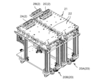
- FIG. 4 is a perspective view showing an example in which the linear transport system shown in FIG. 3 is constructed on a base plate of a stand unit.
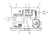
- FIGS. 1 and 2 are a perspective view and a front view showing an example of a linear module for constructing the linear transport system of the present invention.
- the linear transport system 1 is configured by arranging multiple linear modules 2 shown in FIG. 1 in series on the mounting surface of the machine device.
- the linear module 2 includes a module base 3 that is bolted to the mounting surface, a track rail 4 that is fixed to the module base 3, a slider 5 that is attached to the track rail 4, and a carriage 6 that is fixed to the slider 5.
- the track rail 4 and the slider 5 form a linear guide, and the slider 5 is attached to the track rail 4 via a large number of rolling elements and has an infinite circulation path for the large number of rolling elements. Therefore, the slider 5 can freely reciprocate in the longitudinal direction of the track rail 4, and the carriage 6 fixed to the slider 5 can freely move on the module base 3 along the longitudinal direction of the track rail 4.
- the track rail 4 is positioned relative to the module base 3, and when the module base 3 is positioned and fixed to the mounting surface of a mechanical device, the track rail 4 is positioned relative to the mounting surface, and the carriage 6 can be moved with high precision on the mounting surface.
- any known linear guide can be selected and used depending on the required movement accuracy and load bearing capacity of the carriage 6.
- a thrust force is applied to the carriage 6 by the linear motor 7 along the longitudinal direction of the track rail 4.
- Coil members 7a serving as stators of the linear motor 7 are arranged along the track rail 4 on the module base 3, while magnet members 7b serving as movers of the linear motor 7 are provided on the carriage 6.
- the magnet members 7b have a structure in which north and south poles are arranged alternately along the movement direction of the carriage 6.
- a linear scale 8a is provided on the carriage 6, while an encoder 8b is provided on the module base 3 at a position opposite the linear scale 8a, so that an output signal according to the amount of movement of the carriage 6 relative to the module base 3 can be obtained from the encoder 8b. Therefore, by controlling the drive signal applied to the linear motor 7 based on the output signal of the encoder 8b, it is possible to arbitrarily control the amount of movement of the carriage 6 on the module base 3.
- the combination of the linear scale 8a and encoder 8b can be any type, such as magnetic or optical.
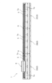
- FIG. 3 is a side view showing a linear transport system 1 configured by arranging three linear modules 2A, 2B, and 2C in series along the longitudinal direction of the track rail.
- the carriage 6 and the slider 5 are provided only on one linear module 2A among the three linear modules 2A, 2B, and 2C, and the slider 5 can reciprocate over the entire length of the linear transport system 1 while riding on the track rails 4 arranged on each linear module 2A, 2B, and 2C.
- FIG. 3 shows an example in which three linear modules 2A, 2B, and 2C are arranged in series, the number of linear modules to be arranged can be determined arbitrarily depending on the scale of the required linear transport system.
- the total length of the track rail 4 in each linear module 2 is set slightly shorter than the total length of the module base 3, and a part of the rail mounting surface 30 is exposed at both ends of the module base 3. Therefore, when two linear modules 2 are arranged in series and fixed to the mounting surface of a machine device, the end of the track rail 4 of one linear module 2 and the end of the track rail 4 of the other linear module 2 are separated by a gap.
- a connecting rail 9 is arranged at the boundary between the linear module 2A and the linear module 2B and the boundary between the linear module 2B and the linear module 2C, and the connecting rail 9 is fixed to the rail mounting surface 30 of each linear module 2 so as to straddle the two adjacent linear modules.
- the track rails of the three linear modules 2A, 2B, and 2C arranged in series are configured as a single guide track.
- the track rails 4 fixed to each module base 3 are connected in series via the connecting rail 9, forming a single long guide track.
- the carriage 6 attached to any linear module 2 can move continuously over the three linear modules 2A, 2B, and 2C along the guide track. Therefore, when the coil member 7a provided on each linear module 2 is energized, the carriage 6 fixed to the slider 5 is propelled by the linear motor 7 and moves back and forth freely within the path formed by the three linear modules 2A, 2B, and 2C. Therefore, by increasing or decreasing the number of linear modules 2 arranged in series, the path length can be changed as desired to construct the linear transport system 1.
- the linear transport system 1 formed by multiple linear modules 2 can also include multiple carriages 6, in which case it is possible to give each carriage 6 an individual movement independent of the other carriages 6.
- the connecting member 10 is used to keep the positional deviation between the two adjacent linear modules 2A, 2B within a predetermined range.
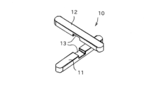
- the connecting member 10 is composed of a rod-shaped axis fixing member 11 arranged along the connecting direction of the two linear modules 2A, 2B, and a rod-shaped spacing adjustment member 12 extending in a direction perpendicular to the axis fixing member 11.
- Each of the axis fixing member 11 and the spacing adjustment member 12 is a prism-shaped member with a rectangular cross section perpendicular to the longitudinal direction, and a recess 13 is formed near the center in the longitudinal direction, making it possible to combine the axis fixing member 11 and the spacing adjustment member 12 perpendicular to each other.
- an alignment groove 14 into which the axis fixing member 11 fits is formed on the bottom surface of the module base 3.
- This alignment groove 14 extends in the same direction as the longitudinal direction of the track rail 4 fixed to the module base 3, and one end of the alignment groove 14 is open to the end surface of the module base 3. Therefore, when two linear modules 2A, 2B are arranged in series, the alignment groove 14 formed in the module base 3 of one linear module 2A and the alignment groove 14 formed in the module base 3 of the other linear module 2B are arranged as one groove, and the axis fixing member 11 can be fitted into the groove while straddling the two linear modules 2A, 2B.
- the mounting unit 21 constitutes a production line that can perform various processing and assembly on a workpiece while transporting the workpiece along the connection direction of the multiple mounting modules 20.
- the mounting unit 21 by rearranging the arrangement of the multiple mounting modules 20, the order of various processing and assembly on the workpiece can be arbitrarily changed, making it easy to rearrange the configuration of the production line.
- the linear modules 2A and 2C of the linear transport system 1 are fixed in advance to the base plate 22 of each of the mounting modules 20A and 20B so that they are positioned in the same straight line.
- a certain gap is created between the linear module 2A fixed to the base plate 22 of one mounting module 20A and the linear module 2C fixed to the base plate 22 of the other mounting module 20B, and this gap is, for example, the width of one of the linear modules 2B.
- the linear module 2B is inserted between the linear module 2A and the linear module 2C so as to straddle the boundary between these mounting modules, and the linear module 2B is fixed to each base plate 22, and the three linear modules 2A, 2B, and 2C are connected in series.
- the connecting member 10 can be used to align the axes of the track rails 4 included in each of the three linear modules 2A, 2B, and 2C within a predetermined error range, and a predetermined amount of gap can be formed between the end faces of the track rails 4 that face each other.
- This allows the carriage 6 to move smoothly between the three linear modules 2A, 2B, and 2C arranged in series, and when electricity is applied to the coil members 7 provided on each linear module 2, the carriage 6 is propelled by the linear motor 7 and can reciprocate on the two frame modules 20A and 20B.
- a linear transport system 1 can be constructed that can transport work through multiple frame modules.
- both the axis fixing member 11 and the distance adjustment member 12 are arranged between two adjacent linear modules 2.
- the distance between the end faces of the track rails 5 facing each other can be appropriately maintained by butting the module bases 3 against each other, it is also possible to use only the axis fixing member 11 without using the distance adjustment member 12.
Landscapes
- Engineering & Computer Science (AREA)
- Physics & Mathematics (AREA)
- Chemical & Material Sciences (AREA)
- Combustion & Propulsion (AREA)
- Electromagnetism (AREA)
- Power Engineering (AREA)
- General Engineering & Computer Science (AREA)
- Mechanical Engineering (AREA)
- Non-Mechanical Conveyors (AREA)
- Bearings For Parts Moving Linearly (AREA)
- Linear Motors (AREA)
Abstract
Description
本発明は、架台等の機械装置の取付け面に対して複数のモジュールベースを直列に配置することで設置規模を容易に変更することが可能なリニア搬送システムに関する。 The present invention relates to a linear transport system that allows the installation scale to be easily changed by arranging multiple module bases in series on the mounting surface of a mechanical device such as a stand.
特許文献1には、架台上に設けられた取付け面に対して複数のモシーュールベースを直列に配置し、リニア搬送システムを構築する例が開示されている。前記モジュールベースにはリニアガイドの軌道レールが位置決めされると共に、かかる軌道レールに沿ってリニアモータ固定子が配置されている。また、前記軌道レールにはリニアガイドのスライダが組付けられると共に、当該スライダにはリニアモータ可動子を備えたキャリッジが装着されている。
このため、複数のモジュールベースを前記取付け面上で直列に配置して、各モジュールベースに含まれる軌道レールを繋ぎ合わせることで、リニアモータによって推進されるキャリッジが複数のモジュールベースの上を連続的に移動可能なリニア搬送システムが構築される。このようなリニア搬送システムは例えば製品の生産ラインにおけるワークの搬送などに使用される。その際、組み合わせるモジュールベースの数を任意に変更することにより、リニア搬送システムの規模を容易に変更することが可能であり、製品の生産ラインの組み換えを容易に行うことが可能である。 For this reason, by arranging multiple module bases in series on the mounting surface and connecting the track rails included in each module base, a linear transport system is constructed in which a carriage driven by a linear motor can move continuously over the multiple module bases. Such linear transport systems are used, for example, to transport workpieces in product production lines. In this case, by arbitrarily changing the number of module bases to be combined, the scale of the linear transport system can be easily changed, and the product production line can be easily rearranged.
その一方、取付け面上に複数のモジュールベースを組付ける際には、互いに隣接して配置された二基のモジュールベースの位置決めが極めて重要である。仮に前記取付け面上におけるモジュールベースの位置決め精度が低い場合には、一方のモジュールベースに含まれる軌道レールの端部と他方のモジュールベースに含まれる軌道レールの端部とが正しく接続されず、前記キャリッジの円滑な移動が損なわれてしまう。 On the other hand, when assembling multiple module bases on a mounting surface, the positioning of the two module bases arranged adjacent to each other is extremely important. If the positioning accuracy of the module bases on the mounting surface is low, the end of the track rail included in one module base and the end of the track rail included in the other module base will not be connected correctly, impairing the smooth movement of the carriage.
また、製品の生産ラインの組み換えを容易に行えるといった観点からすれば、熟練作業者でなくても互いに隣接して配置された二基のモジュールベースの位置決めを短時間で容易に行えることが重要である。 In addition, from the perspective of easily rearranging a product production line, it is important that even unskilled workers can easily position two module bases that are placed next to each other in a short amount of time.
本発明はこのような課題に鑑みなされたものであり、その目的とするところは、機械装置の取付け面に対して複数のモジュールベースを組付けてリニア搬送システムを構築するに際して、熟練作業者でなくても互いに隣接して配置されたモジュールベースの位置決めを短時間で容易に行うことができると共に、配置されるリニアモジュールの基数を容易に変更可能であり、製品の生産ラインの組み換えを容易に行うことが可能なリニア搬送システムを提供することにある。 The present invention has been made in consideration of these problems, and its purpose is to provide a linear transport system that allows even unskilled workers to easily position adjacent module bases in a short time when assembling multiple module bases to the mounting surface of a machine device to construct a linear transport system, and that allows the number of linear modules to be easily changed and product production lines to be easily rearranged.
すなわち、本発明は、リニアガイドの軌道レールが位置決め固定された複数のモジュールベースを機械装置の取付け面に対して直列に配置し、一の軌道レールに組付けられたスライダが複数の軌道レールを順次乗り移りながら移動可能なリニア搬送システムであって、各モジュールベースの底面には、隣接するモジュールベースに向けて開放されると共に前記軌道レールの長手方向に合致して延びる位置合わせ溝が形成される一方、互いに隣接するモジュールベースに跨って前記位置合わせ溝に嵌合する棒状の軸決め部材が設けられ、各モジュールベースは前記軸決め部材を前記位置合わせ溝に嵌合させた状態で前記取付け面に固定されている。 In other words, the present invention is a linear transport system in which multiple module bases, with the track rails of a linear guide positioned and fixed, are arranged in series on the mounting surface of a mechanical device, and a slider attached to one track rail can move while sequentially moving between the multiple track rails. The bottom surface of each module base is formed with an alignment groove that is open toward the adjacent module base and extends in the longitudinal direction of the track rail, while a rod-shaped alignment member that fits into the alignment groove is provided across the adjacent module bases, and each module base is fixed to the mounting surface with the alignment member fitted into the alignment groove.
このような本発明によれば、機械装置の取付け面に対して複数のモジュールベースを組付けてリニア搬送システムを構築するに際して、熟練作業者でなくても互いに隣接して配置されたモジュールベースの位置決めを短時間で容易に行うことができると共に、そのリニア搬送システムの規模を容易に変更可能であり、製品の生産ラインの組み換えを容易に行うことが可能となる。 According to the present invention, when assembling multiple module bases to the mounting surface of a machine to construct a linear conveying system, even an unskilled worker can easily position adjacent module bases in a short time, and the scale of the linear conveying system can be easily changed, making it easy to rearrange the product production line.
以下、添付図面を用いながら本発明のリニア搬送システムを詳細に説明する。 The linear transport system of the present invention will be described in detail below with reference to the attached drawings.
図1及び図2は本発明のリニア搬送システムを構築するためのリニアモジュールの一例を示す斜視図及び正面図である。前記リニア搬送システム1は図1に示すリニアモジュール2の複数基を機械装置の取付け面に対して直列に配置して構成される。
FIGS. 1 and 2 are a perspective view and a front view showing an example of a linear module for constructing the linear transport system of the present invention. The
前記リニアモジュール2は、前記取付け面に対してボルト固定されるモジュールベース3と、このモジュールベース3に対して固定された軌道レール4と、前記軌道レール4に組付けられたスライダ5と、前記スライダ5に固定されたキヤリッジ6と、を備えている。前記軌道レール4と前記スライダ5はリニアガイドを構成しており、当該スライダ5は多数の転動体を介して前記軌道レール4に組付けられると共に、前記多数の転動体の無限循環路を備えている。このため、前記スライダ5は前記軌道レール4の長手方向へ自在に往復運動可能であり、当該スライダ5に固定されたキャリッジ6は前記モジュールベース3上を前記軌道レール4の長手方向へ沿って自在に移動可能である。また、前記軌道レール4は前記モジュールベース3に対して位置決めされており、当該モジュールベース3を機械装置の取付け面に対して位置決め固定すると、前記軌道レール4が前記取付け面に対して位置決めされ、前記キャリッジ6を前記取付け面上で高精度に移動させることが可能である。尚、これら軌道レール4とスライダ5の組み合わせとしては、必要とされる前記キャリッジ6の移動精度、荷重負荷能力に応じて公知のリニアガイドを任意に選択して使用することができる。
The
また、この実施形態におけるリニア搬送システム1では前記キャリッジ6対してリニアモータ7によって前記軌道レール4の長手方向に沿った推力が与えられる。前記モジュールベース3にはリニアモータ7の固定子としてのコイル部材7aが前記軌道レール4に沿って配列される一方、前記キャリッジ6にはリニアモータ7の可動子としてのマグネット部材7bが設けられている。前記マグネット部材7bは前記キャリッジ6の移動方向に沿ってN極とS極を交互に配列した構造となっている。
In addition, in the
更に、前記キャリッジ6にはリニアスケール8aが設けられる一方、前記モジュールベース3には前記リニアスケール8aと対向する位置にエンコーダ8bが設けられており、前記モジュールベース3に対する前記キャリッジ6の移動量に応じた出力信号を前記エンコーダ8bから得られるようになっている。従って、前記リニアモータ7に印加する駆動信号を前記エンコーダ8bの出力信号に基づいて制御することにより、前記モジュールベース3上での前記キャリッジ6の移動量を任意に制御することが可能である。尚、これらリニアスケール8aとエンコーダ8bの組み合わせは、磁気式や光学式等の任意の方式を選択することができる。
Furthermore, a
図3は三基のリニアモジュール2A,2B,2Cを前記軌道レールの長手方向に沿って直列に配置して構成したリニア搬送システム1を示す側面図である。同図に示したリニア搬送システム1では、三基のリニアモジュール2A,2B,2Cのうち、前記キャリッジ6及び前記スライダ5は一基のリニアモジュール2Aにのみ設けられており、前記スライダ5は各リニアモジュール2A,2B,2Cに配設された軌道レール4を乗り移りながら、このリニア搬送システム1の全長にわたって往復運動することが可能である。尚、図3では三基のリニアモジュール2A,2B,2Cを直列に配置した例を示しているが、配置するリニアモジュールの基数は必要とするリニア搬送システムの規模に応じて任意に決定することが可能である。
FIG. 3 is a side view showing a
図1に示されるように、各リニアモジュール2ではモジュールベース3の全長よりも軌道レール4の全長の方がわずかに短く設定されており、当該モジュールベース3の両端にはレール取付け面30の一部が露出している。このため、二基のリニアモジュール2を直列に配置して機械装置の取付け面に固定した場合に、一方のリニアモジュール2の軌道レール4の端部と他方のリニアモジュール2の軌道レール4の端部とは隙間を介して離間した状態となる。図3に示すリニア搬送システムでは、リニアモジュール2Aとリニアモジュール2Bの境界部、リニアモジュール2Bとリニアモジュール2Cの境界部に対して連結レール9が配置され、当該連結レール9は互いに隣接する二基のリニアモジュールを跨ぐようにして各リニアモジュール2のレール取付け面30に固定される。これにより、直列に配置された三基のリニアモジュール2A,2B,2Cの軌道レールが一本の案内軌道として構成される。
As shown in FIG. 1, the total length of the
このようにして三基のリニアモジュール2A,2B,2Cを直列に配置して位置決め固定すると、各モジュールベース3に固定された軌道レール4が前記連結レール9を介して直列に結合され、長尺な一本の案内軌道が構成される。いずれかのリニアモジュール2に組付けられたキャリッジ6は当該案内軌道に沿って三基のリニアモジュール2A,2B,2Cの上を連続的に移動することが可能となる。このため、各リニアモジュール2に設けられたコイル部材7aに通電すると、前記スライダ5に固定されたキャリッジ6はリニアモータ7によって推進され、三基のリニアモジュール2A,2B,2Cによって構成された経路内を自在に往復運動することになる。従って、直列に配置するリニアモジュール2の基数を増減することにより、経路長を任意に変更してリニア搬送システム1を構築することができる。尚、複数のリニアモジュール2によって構成されたリニア搬送システム1は複数基のキャリッジ6を含むことも可能であり、その場合は各キャリッジ6に対して他のキャリッジ6から独立した個別の運動を与えることも可能である。
When the three
前記リニアモジュール2を機械装置の取付け面に対して固定する際には、図4に示すように、互いに隣接する二基のリニアモジュール2A,2Bの相互間の位置ずれを所定の範囲内に収めるために、連結部材10が用いられる。図5に示すように、この連結部材10は、二基のリニアモジュール2A,2Bの連結方向に沿って配置される棒状の軸決め部材11と、前記軸決め部材11と直交する方向へ延びる棒状の間隔調整部材12と、から構成されている。前記軸決め部材11及び前記間隔調整部材12のそれぞれは長手方向に直交する断面が長方形状に形成された角柱状の部材であり、長手方向の中央付近には凹所13が形成されて、前記軸決め部材11及び前記間隔調整部材12の両者を直交させて組み合わせることが可能となっている。
When the
一方、図6に示すように、前記モジュールベース3の底面には前記軸決め部材11が嵌合する位置合わせ溝14が形成されている。この位置合わせ溝14は前記モジュールベース3に固定された軌道レール4の長手方向と合致して延びており、当該位置合わせ溝14の一端は前記モジュールベース3の端面に開放されている。従って、二基のリニアモジュール2A,2Bを直列に配置した場合に、一方のリニアモジュール2Aのモジュールベース3に形成された位置合わせ溝14と他方のリニアモジュール2Bのモジュールベース3に形成されたそれとが一つの溝として配置され、当該溝に前記軸決め部材11を二基のリニアモジュール2A,2Bに跨った状態で嵌合させることが可能となる。
On the other hand, as shown in FIG. 6, an
また、前記モジュールベース3の底面には前記位置合わせ溝14と直行する隙間調整溝15が形成されている。この隙間調整溝15は前記モジュールベース3の長手方向の端部、すなわち隣接配置される他のモジュールベース3に面した位置に設けられており、前記軌道レール4の幅方向に合致して延びている。そして、二基のリニアモジュール2A,2Bを前記キャリッジ6の移動方向に沿って直列に配置した場合に、それぞれのモジュールベース3に形成された隙間調整溝15が互いに向かい合い、前記間隔調整部材12を収容する溝が形成されるようになっている。
In addition, a
そして、機械装置の取付け面に対してリニア搬送システム1を組付ける際には、図6に示すように、軌道レール5の長手方向に沿って直列に配置される二基のリニアモジュール2A,2Bのそれぞれのモジュールベース3の間に前記軸決め部材11及び前記間隔調整部材12を配置して、前記取付け面に対するこれらリニアモジュール2A,2Bの相互の固定位置を調整する。すなわち、二基のリニアモジュール2A,2Bに跨って前記軸決め部材11を前記位置合わせ溝14に嵌合させると、一方のリニアモジュール2Aの軌道レール4の軸心と他方のリニアモジュール2Bの軌道レール4の軸心とを所定の誤差の範囲内で正対させ、その上で各リニアモジュール2A,2Bを機械装置の取付け面に対して固定することができ、直列に配置された二基のリニアモジュール2A,2Bの間における前記キャリッジ6の乗り移りを円滑に行うことが可能となる。
When assembling the
また、二基のリニアモジュール2A,2Bに跨って前記間隔調整部材12を前記隙間調整溝15に嵌合させ、かかる間隔調整部材12を挟み込むようにしてこれらリニアモジュール2A,2Bを前記取付け面に固定すると、一方のリニアモジュール2Aの軌道レール4の端面と他方のリニアモジュール2Bの軌道レール4の端面との間隔を適切に設定することができ、一方のリニアモジュール2Aと他方のリニアモジュール2Bとの境界に前記連結レール9を配置した場合に、直列に配置された二基のリニアモジュール2A,2Bの軌道レール4を前記連結レール9で適切に接続して、前記キャリッジ6の円滑な移動を確保することが可能となる。
Furthermore, by fitting the
尚、前記間隔調整部材12は前記軸決め部材11と組み合わせて前記モジュールベース3の下面側に配置する必要はない。例えば、機械装置の取付け面に二基のリニアモジュール2A,2Bを仮固定した後に、前記隙間調整溝15の長手方向の両端から当該隙間調整溝15に対して前記間隔調整部材12を挿入するようにしてもよい。この場合、当該間隔調整部材12によって二基のリニアモジュール2A,2Bの間隔を適切に設定した後に、これらリニアモジュール2A,2Bを機械装置の取付け面へ本固定することで、直列に配置された二基のリニアモジュール2A,2Bを適切に配置して、前記キャリッジ6の円滑な移動を確保することが可能となる。
The
図7は、複数の架台モジュール20を連結して構成した架台ユニット21に対して前記リニア搬送システム1を設置する様子を示す斜視図である。
Figure 7 is a perspective view showing the
この架台ユニット21は複数基の架台モジュール20を一列に連結して使用することが可能であり、図7は二基の架台モジュール20A,20Bを連結した状態を示している。各架台モジュール20にはベースプレート22が設けられており、当該ベースプレート22に各種加工機やロボットアーム等を据え付けることによって、ワークに対する加工又は組立の工程のいずれかを分担させることが可能である。前記架台ユニット1には複数基の架台モジュール20を貫くリニア搬送システム1を設けることが可能であり、このリニア搬送システム1を用いることで、加工や組み立ての対象となるワークを複数基の架台モジュール20の連結方向に沿って自在に搬送することができる。
This mounting
すなわち、前記架台ユニット21は複数基の架台モジュール20の連結方向に沿ってワークを搬送しながら当該ワークに対して各種加工や組み立てを行うことが可能な生産ラインを構成するものである。また、複数基の架台モジュール20の配列を組み替えることにより、ワークに対する各種加工や各種組立の順番を任意に入れ替え、生産ラインの構成の組み換えを容易に行えるようになっている。
In other words, the mounting
図7に示すように、各架台モジュール20A,20Bのベースプレート22には前記リニア搬送システム1のリニアモジュール2A,2Cが同一直線状に位置するように予め固定されている。二基の架台モジュール20A,20Bを連結すると、一方の架台モジュール20Aのベースプレート22に固定されたリニアモジュール2Aと他方の架台モジュール20Bのベースプレート22に固定されたリニアモジュール2Cの間には所定の間隔が生じるが、例えばこの間隔は前記リニアモジュール2Bの一基分となっている。このため、二基の架台モジュール20A,20Bを相互に連結した後に、これら架台モジュールの境界を跨ぐようにしてリニアモジュール2Bをリニアモジュール2Aとリニアモジュール2Cの間に挿入して、当該リニアモジュール2Bを各ベースプレート22に固定すると、三基のリニアモジュール2A,2B,2Cが直列に結合される。
As shown in FIG. 7, the
前記リニアモジュール2Bの固定に際しては、前記連結部材10を使用することにより、三基のリニアモジュール2A,2B,2Cのそれぞれに含まれる軌道レール4の軸心を所定の誤差の範囲内で正対させることができると共に、互いに対向する軌道レール4の端面の間に所定量のすき間を形成することができる。このため、直列に配置された三基のリニアモジュール2A,2B,2Cの間における前記キャリッジ6の乗り移りを円滑に行うことが可能となり、各リニアモジュール2に設けられたコイル部材7に通電すると、前記キャリッジ6はリニアモータ7によって推進されて、これら二基の架台モジュール20A,20Bの上で往復運動することが可能となる。例えば、前記キャリッジ6にワークテーブルを固定すれば、複数基の架台モジュールを貫いてワークを搬送可能なリニア搬送システム1を構築することができる。
When the
尚、図を用いて説明した本発明の実施形態では、互いに隣接する二基のリニアモジュール2の間に前記軸決め部材11と前記間隔調整部材12の双方を配置した例を説明したが、前記モジュールベース3同士を互いに突き当てることで、互いに正対する軌道レール5の端面の間隔を適切に保つことができるのであれば、前記間隔調整部材12は用いずに前記軸決め部材11のみを用いるようにしても差し支えない。
In the embodiment of the present invention described using the figures, an example was described in which both the
Claims (4)
各モジュールベース(3)の底面には、隣接するモジュールベース(3)に向けて開放されると共に前記軌道レール(4)の長手方向に合致して延びる位置合わせ溝(14)が形成される一方、
互いに隣接するモジュールベース(3)に跨って前記位置合わせ溝(14)に嵌合する棒状の軸決め部材(11)が設けられ、
各モジュールベース(3)は前記軸決め部材(11)を前記位置合わせ溝(14)に嵌合させた状態で前記取付け面に固定されることを特徴とするリニア搬送システム。 A linear conveyance system in which a plurality of module bases (3) on which track rails (4) of a linear guide are positioned and fixed are arranged in series on a mounting surface of a machine device, and a slider (5) attached to one track rail (4) can move while sequentially moving between the plurality of track rails (4),
An alignment groove (14) is formed on the bottom surface of each module base (3), the alignment groove (14) being open toward the adjacent module base (3) and extending in accordance with the longitudinal direction of the track rail (4);
A rod-shaped axis positioning member (11) is provided to straddle the adjacent module bases (3) and to fit into the alignment groove (14),
A linear transport system, characterized in that each module base (3) is fixed to the mounting surface with the axis alignment member (11) fitted into the alignment groove (14).
互いに隣接するモジュールベース(3)に跨って前記隙間調整溝(15)に嵌合する棒状の間隔調整部材(12)が設けられ、
各モジュールベース(3)は前記レール間隔調整部材(12)を前記隙間調整溝(15)に嵌合させた状態で前記取付け面に固定され、互いに隣接するモジュールベース(3)間に所定の隙間が形成されることを特徴とする請求項1記載のリニア搬送システム。 A gap adjustment groove (15) is formed on the bottom surface of each module base (3), the gap adjustment groove (15) is open toward the adjacent module base (3) and extends in the width direction of the track rail (4).
A rod-shaped gap adjustment member (12) is provided to straddle the adjacent module bases (3) and to fit into the gap adjustment groove (15),
2. The linear conveying system according to claim 1, wherein each module base (3) is fixed to the mounting surface with the rail spacing adjustment member (12) fitted into the gap adjustment groove (15), so that a predetermined gap is formed between adjacent module bases (3).
各モジュールベース(3)には複数のコイルユニットが前記軌道レール(4)の長手方向に沿って配列される一方、前記キャリッジ(6)にはマグネット部材(7b)が設けられ、
これら複数のコイルユニットとマグネット部材(7b)が対向して前記キャリッジ(6)に推力を与えるリニアモータ(7)が構成されることを特徴とする請求項1記載のリニア搬送システム。 A carriage (6) serving as a work table is fixed to the slider (5),
A plurality of coil units are arranged on each module base (3) along the longitudinal direction of the track rail (4), while a magnet member (7b) is provided on the carriage (6);
2. The linear transport system according to claim 1, wherein the plurality of coil units and a magnet member (7b) face each other to constitute a linear motor (7) for applying a thrust to the carriage (6).
Applications Claiming Priority (2)
| Application Number | Priority Date | Filing Date | Title |
|---|---|---|---|
| JP2023-095390 | 2023-06-09 | ||
| JP2023095390A JP2024176662A (en) | 2023-06-09 | 2023-06-09 | Linear Transport System |
Publications (1)
| Publication Number | Publication Date |
|---|---|
| WO2024252836A1 true WO2024252836A1 (en) | 2024-12-12 |
Family
ID=93795316
Family Applications (1)
| Application Number | Title | Priority Date | Filing Date |
|---|---|---|---|
| PCT/JP2024/017134 Ceased WO2024252836A1 (en) | 2023-06-09 | 2024-05-08 | Linear conveyance system |
Country Status (3)
| Country | Link |
|---|---|
| JP (1) | JP2024176662A (en) |
| TW (1) | TW202500493A (en) |
| WO (1) | WO2024252836A1 (en) |
Citations (3)
| Publication number | Priority date | Publication date | Assignee | Title |
|---|---|---|---|---|
| JP2014194271A (en) * | 2012-08-24 | 2014-10-09 | Nsk Ltd | Linear guide device |
| JP2017211089A (en) * | 2017-09-07 | 2017-11-30 | 岡田装飾金物株式会社 | Connecting member and connecting structure including the same |
| JP7197730B2 (en) * | 2019-12-17 | 2022-12-27 | ヤマハ発動機株式会社 | Conveyor |
-
2023
- 2023-06-09 JP JP2023095390A patent/JP2024176662A/en active Pending
-
2024
- 2024-05-08 WO PCT/JP2024/017134 patent/WO2024252836A1/en not_active Ceased
- 2024-05-20 TW TW113118499A patent/TW202500493A/en unknown
Patent Citations (3)
| Publication number | Priority date | Publication date | Assignee | Title |
|---|---|---|---|---|
| JP2014194271A (en) * | 2012-08-24 | 2014-10-09 | Nsk Ltd | Linear guide device |
| JP2017211089A (en) * | 2017-09-07 | 2017-11-30 | 岡田装飾金物株式会社 | Connecting member and connecting structure including the same |
| JP7197730B2 (en) * | 2019-12-17 | 2022-12-27 | ヤマハ発動機株式会社 | Conveyor |
Also Published As
| Publication number | Publication date |
|---|---|
| TW202500493A (en) | 2025-01-01 |
| JP2024176662A (en) | 2024-12-19 |
Similar Documents
| Publication | Publication Date | Title |
|---|---|---|
| US12187552B2 (en) | Linear motor conveyor system with diverter and method for design and configuration thereof | |
| US10273096B2 (en) | Conveyor bearing system | |
| EP3626986B1 (en) | Table circulation guidance device | |
| US6495935B1 (en) | Linear motor drive unit | |
| WO2019007198A1 (en) | Linear transport system | |
| KR20110018835A (en) | Straight Motion Motor System | |
| WO2018055709A1 (en) | Linear conveyor device | |
| JP2016531534A (en) | Linear motor transport for packaging and other applications | |
| JP3695542B2 (en) | XY drive device with linear electromagnetic actuator | |
| JPH0480782B2 (en) | ||
| CN103228404B (en) | Align the stage | |
| US3881139A (en) | 3-Axis pulse operated linear motor | |
| US3832610A (en) | Pulse operated surface motor | |
| WO2024252836A1 (en) | Linear conveyance system | |
| JP2019103225A (en) | Transport apparatus, processing system, and manufacturing method of article | |
| US5732592A (en) | Pivotally linked position control drive system | |
| WO2024252837A1 (en) | Stand unit and linear conveyance system | |
| JP2006054971A (en) | Linear motor for machine tools | |
| US6504648B2 (en) | Compensation mechanism for component and assembly deviation in a component precision positioning stage | |
| US20250282564A1 (en) | Transport system | |
| US5887334A (en) | Method for splicing a linear stepper motor platen | |
| EP0957051B1 (en) | Linear conveyor for article supporting means | |
| JPH0398457A (en) | Linear motor | |
| JPH0480783B2 (en) | ||
| JPS62159812A (en) | Linear giuding device |
Legal Events
| Date | Code | Title | Description |
|---|---|---|---|
| 121 | Ep: the epo has been informed by wipo that ep was designated in this application |
Ref document number: 24819073 Country of ref document: EP Kind code of ref document: A1 |
|
| NENP | Non-entry into the national phase |
Ref country code: DE |