WO2024252836A1 - Système de transport linéaire - Google Patents
Système de transport linéaire Download PDFInfo
- Publication number
- WO2024252836A1 WO2024252836A1 PCT/JP2024/017134 JP2024017134W WO2024252836A1 WO 2024252836 A1 WO2024252836 A1 WO 2024252836A1 JP 2024017134 W JP2024017134 W JP 2024017134W WO 2024252836 A1 WO2024252836 A1 WO 2024252836A1
- Authority
- WO
- WIPO (PCT)
- Prior art keywords
- linear
- module
- module base
- mounting surface
- modules
- Prior art date
- Legal status (The legal status is an assumption and is not a legal conclusion. Google has not performed a legal analysis and makes no representation as to the accuracy of the status listed.)
- Ceased
Links
Images



Classifications
-
- B—PERFORMING OPERATIONS; TRANSPORTING
- B65—CONVEYING; PACKING; STORING; HANDLING THIN OR FILAMENTARY MATERIAL
- B65G—TRANSPORT OR STORAGE DEVICES, e.g. CONVEYORS FOR LOADING OR TIPPING, SHOP CONVEYOR SYSTEMS OR PNEUMATIC TUBE CONVEYORS
- B65G54/00—Non-mechanical conveyors not otherwise provided for
- B65G54/02—Non-mechanical conveyors not otherwise provided for electrostatic, electric, or magnetic
-
- F—MECHANICAL ENGINEERING; LIGHTING; HEATING; WEAPONS; BLASTING
- F16—ENGINEERING ELEMENTS AND UNITS; GENERAL MEASURES FOR PRODUCING AND MAINTAINING EFFECTIVE FUNCTIONING OF MACHINES OR INSTALLATIONS; THERMAL INSULATION IN GENERAL
- F16C—SHAFTS; FLEXIBLE SHAFTS; ELEMENTS OR CRANKSHAFT MECHANISMS; ROTARY BODIES OTHER THAN GEARING ELEMENTS; BEARINGS
- F16C29/00—Bearings for parts moving only linearly
- F16C29/04—Ball or roller bearings
- F16C29/06—Ball or roller bearings in which the rolling bodies circulate partly without carrying load
-
- H—ELECTRICITY
- H02—GENERATION; CONVERSION OR DISTRIBUTION OF ELECTRIC POWER
- H02K—DYNAMO-ELECTRIC MACHINES
- H02K41/00—Propulsion systems in which a rigid body is moved along a path due to dynamo-electric interaction between the body and a magnetic field travelling along the path
- H02K41/02—Linear motors; Sectional motors
-
- H—ELECTRICITY
- H02—GENERATION; CONVERSION OR DISTRIBUTION OF ELECTRIC POWER
- H02K—DYNAMO-ELECTRIC MACHINES
- H02K41/00—Propulsion systems in which a rigid body is moved along a path due to dynamo-electric interaction between the body and a magnetic field travelling along the path
- H02K41/02—Linear motors; Sectional motors
- H02K41/03—Synchronous motors; Motors moving step by step; Reluctance motors
Definitions
- the present invention relates to a linear transport system that allows the installation scale to be easily changed by arranging multiple module bases in series on the mounting surface of a mechanical device such as a stand.
- Patent Document 1 discloses an example of constructing a linear transport system by arranging multiple module bases in series on a mounting surface provided on a frame.
- a linear guide track rail is positioned on the module base, and a linear motor stator is arranged along the track rail.
- a linear guide slider is attached to the track rail, and a carriage equipped with a linear motor mover is attached to the slider.
- a linear transport system is constructed in which a carriage driven by a linear motor can move continuously over the multiple module bases.
- Such linear transport systems are used, for example, to transport workpieces in product production lines.
- the scale of the linear transport system can be easily changed, and the product production line can be easily rearranged.
- the positioning of the two module bases arranged adjacent to each other is extremely important. If the positioning accuracy of the module bases on the mounting surface is low, the end of the track rail included in one module base and the end of the track rail included in the other module base will not be connected correctly, impairing the smooth movement of the carriage.
- the present invention has been made in consideration of these problems, and its purpose is to provide a linear transport system that allows even unskilled workers to easily position adjacent module bases in a short time when assembling multiple module bases to the mounting surface of a machine device to construct a linear transport system, and that allows the number of linear modules to be easily changed and product production lines to be easily rearranged.
- the present invention is a linear transport system in which multiple module bases, with the track rails of a linear guide positioned and fixed, are arranged in series on the mounting surface of a mechanical device, and a slider attached to one track rail can move while sequentially moving between the multiple track rails.
- the bottom surface of each module base is formed with an alignment groove that is open toward the adjacent module base and extends in the longitudinal direction of the track rail, while a rod-shaped alignment member that fits into the alignment groove is provided across the adjacent module bases, and each module base is fixed to the mounting surface with the alignment member fitted into the alignment groove.
- the present invention when assembling multiple module bases to the mounting surface of a machine to construct a linear conveying system, even an unskilled worker can easily position adjacent module bases in a short time, and the scale of the linear conveying system can be easily changed, making it easy to rearrange the product production line.
- FIG. 1 is an exploded perspective view showing an example of a linear module that constitutes the linear transport system of the present invention
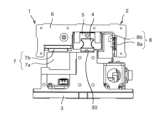
- FIG. 2 is a front view of the linear module shown in FIG.
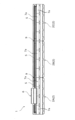
- FIG. 1 is a side view showing a linear transport system configured by arranging three linear modules in series.
- 1 is a perspective view showing how two linear modules are arranged in series using a connecting member.
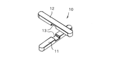
- FIG. FIG. 4 is a perspective view showing a combination of a shaft fixing member and a distance adjusting member.
- FIG. 2 is an exploded perspective view showing the combination state of each linear module with the axis fixing member and the interval adjusting member.
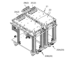
- FIG. 4 is a perspective view showing an example in which the linear transport system shown in FIG. 3 is constructed on a base plate of a stand unit.
- FIGS. 1 and 2 are a perspective view and a front view showing an example of a linear module for constructing the linear transport system of the present invention.
- the linear transport system 1 is configured by arranging multiple linear modules 2 shown in FIG. 1 in series on the mounting surface of the machine device.
- the linear module 2 includes a module base 3 that is bolted to the mounting surface, a track rail 4 that is fixed to the module base 3, a slider 5 that is attached to the track rail 4, and a carriage 6 that is fixed to the slider 5.
- the track rail 4 and the slider 5 form a linear guide, and the slider 5 is attached to the track rail 4 via a large number of rolling elements and has an infinite circulation path for the large number of rolling elements. Therefore, the slider 5 can freely reciprocate in the longitudinal direction of the track rail 4, and the carriage 6 fixed to the slider 5 can freely move on the module base 3 along the longitudinal direction of the track rail 4.
- the track rail 4 is positioned relative to the module base 3, and when the module base 3 is positioned and fixed to the mounting surface of a mechanical device, the track rail 4 is positioned relative to the mounting surface, and the carriage 6 can be moved with high precision on the mounting surface.
- any known linear guide can be selected and used depending on the required movement accuracy and load bearing capacity of the carriage 6.
- a thrust force is applied to the carriage 6 by the linear motor 7 along the longitudinal direction of the track rail 4.
- Coil members 7a serving as stators of the linear motor 7 are arranged along the track rail 4 on the module base 3, while magnet members 7b serving as movers of the linear motor 7 are provided on the carriage 6.
- the magnet members 7b have a structure in which north and south poles are arranged alternately along the movement direction of the carriage 6.
- a linear scale 8a is provided on the carriage 6, while an encoder 8b is provided on the module base 3 at a position opposite the linear scale 8a, so that an output signal according to the amount of movement of the carriage 6 relative to the module base 3 can be obtained from the encoder 8b. Therefore, by controlling the drive signal applied to the linear motor 7 based on the output signal of the encoder 8b, it is possible to arbitrarily control the amount of movement of the carriage 6 on the module base 3.
- the combination of the linear scale 8a and encoder 8b can be any type, such as magnetic or optical.
- FIG. 3 is a side view showing a linear transport system 1 configured by arranging three linear modules 2A, 2B, and 2C in series along the longitudinal direction of the track rail.
- the carriage 6 and the slider 5 are provided only on one linear module 2A among the three linear modules 2A, 2B, and 2C, and the slider 5 can reciprocate over the entire length of the linear transport system 1 while riding on the track rails 4 arranged on each linear module 2A, 2B, and 2C.
- FIG. 3 shows an example in which three linear modules 2A, 2B, and 2C are arranged in series, the number of linear modules to be arranged can be determined arbitrarily depending on the scale of the required linear transport system.
- the total length of the track rail 4 in each linear module 2 is set slightly shorter than the total length of the module base 3, and a part of the rail mounting surface 30 is exposed at both ends of the module base 3. Therefore, when two linear modules 2 are arranged in series and fixed to the mounting surface of a machine device, the end of the track rail 4 of one linear module 2 and the end of the track rail 4 of the other linear module 2 are separated by a gap.
- a connecting rail 9 is arranged at the boundary between the linear module 2A and the linear module 2B and the boundary between the linear module 2B and the linear module 2C, and the connecting rail 9 is fixed to the rail mounting surface 30 of each linear module 2 so as to straddle the two adjacent linear modules.
- the track rails of the three linear modules 2A, 2B, and 2C arranged in series are configured as a single guide track.
- the track rails 4 fixed to each module base 3 are connected in series via the connecting rail 9, forming a single long guide track.
- the carriage 6 attached to any linear module 2 can move continuously over the three linear modules 2A, 2B, and 2C along the guide track. Therefore, when the coil member 7a provided on each linear module 2 is energized, the carriage 6 fixed to the slider 5 is propelled by the linear motor 7 and moves back and forth freely within the path formed by the three linear modules 2A, 2B, and 2C. Therefore, by increasing or decreasing the number of linear modules 2 arranged in series, the path length can be changed as desired to construct the linear transport system 1.
- the linear transport system 1 formed by multiple linear modules 2 can also include multiple carriages 6, in which case it is possible to give each carriage 6 an individual movement independent of the other carriages 6.
- the connecting member 10 is used to keep the positional deviation between the two adjacent linear modules 2A, 2B within a predetermined range.
- the connecting member 10 is composed of a rod-shaped axis fixing member 11 arranged along the connecting direction of the two linear modules 2A, 2B, and a rod-shaped spacing adjustment member 12 extending in a direction perpendicular to the axis fixing member 11.
- Each of the axis fixing member 11 and the spacing adjustment member 12 is a prism-shaped member with a rectangular cross section perpendicular to the longitudinal direction, and a recess 13 is formed near the center in the longitudinal direction, making it possible to combine the axis fixing member 11 and the spacing adjustment member 12 perpendicular to each other.
- an alignment groove 14 into which the axis fixing member 11 fits is formed on the bottom surface of the module base 3.
- This alignment groove 14 extends in the same direction as the longitudinal direction of the track rail 4 fixed to the module base 3, and one end of the alignment groove 14 is open to the end surface of the module base 3. Therefore, when two linear modules 2A, 2B are arranged in series, the alignment groove 14 formed in the module base 3 of one linear module 2A and the alignment groove 14 formed in the module base 3 of the other linear module 2B are arranged as one groove, and the axis fixing member 11 can be fitted into the groove while straddling the two linear modules 2A, 2B.
- the mounting unit 21 constitutes a production line that can perform various processing and assembly on a workpiece while transporting the workpiece along the connection direction of the multiple mounting modules 20.
- the mounting unit 21 by rearranging the arrangement of the multiple mounting modules 20, the order of various processing and assembly on the workpiece can be arbitrarily changed, making it easy to rearrange the configuration of the production line.
- the linear modules 2A and 2C of the linear transport system 1 are fixed in advance to the base plate 22 of each of the mounting modules 20A and 20B so that they are positioned in the same straight line.
- a certain gap is created between the linear module 2A fixed to the base plate 22 of one mounting module 20A and the linear module 2C fixed to the base plate 22 of the other mounting module 20B, and this gap is, for example, the width of one of the linear modules 2B.
- the linear module 2B is inserted between the linear module 2A and the linear module 2C so as to straddle the boundary between these mounting modules, and the linear module 2B is fixed to each base plate 22, and the three linear modules 2A, 2B, and 2C are connected in series.
- the connecting member 10 can be used to align the axes of the track rails 4 included in each of the three linear modules 2A, 2B, and 2C within a predetermined error range, and a predetermined amount of gap can be formed between the end faces of the track rails 4 that face each other.
- This allows the carriage 6 to move smoothly between the three linear modules 2A, 2B, and 2C arranged in series, and when electricity is applied to the coil members 7 provided on each linear module 2, the carriage 6 is propelled by the linear motor 7 and can reciprocate on the two frame modules 20A and 20B.
- a linear transport system 1 can be constructed that can transport work through multiple frame modules.
- both the axis fixing member 11 and the distance adjustment member 12 are arranged between two adjacent linear modules 2.
- the distance between the end faces of the track rails 5 facing each other can be appropriately maintained by butting the module bases 3 against each other, it is also possible to use only the axis fixing member 11 without using the distance adjustment member 12.
Landscapes
- Engineering & Computer Science (AREA)
- Physics & Mathematics (AREA)
- Chemical & Material Sciences (AREA)
- Combustion & Propulsion (AREA)
- Electromagnetism (AREA)
- Power Engineering (AREA)
- General Engineering & Computer Science (AREA)
- Mechanical Engineering (AREA)
- Non-Mechanical Conveyors (AREA)
- Bearings For Parts Moving Linearly (AREA)
- Linear Motors (AREA)
Abstract
La présente invention concerne un système de transport linéaire grâce auquel, lorsque le système de transport linéaire est construit par assemblage d'une pluralité de bases de module sur une surface de montage d'un dispositif mécanique, des bases de module disposées de manière adjacente les unes aux autres peuvent être facilement positionnées dans une courte période de temps même par une personne qui n'est pas un ouvrier qualifié, le nombre de modules linéaires à agencer peut être facilement changé, et une ligne de production de produit peut être facilement réagencée. Des rainures d'alignement (14) dont chacune est ouverte vers une base de module (3) adjacente et s'étend de manière à coïncider avec la direction longitudinale d'un rail de voie (4) sont formées dans la surface inférieure de chaque base de module (3), des éléments de détermination d'axe en forme de tige (11) dont chacun chevauche des bases de module (3) mutuellement adjacentes et est positionné dans les rainures d'alignement (14) sont présents, et les bases de module (3) sont fixées à la surface de montage dans un état dans lequel les éléments de détermination d'axe (11) sont positionnés dans les rainures d'alignement (14).
Applications Claiming Priority (2)
| Application Number | Priority Date | Filing Date | Title |
|---|---|---|---|
| JP2023-095390 | 2023-06-09 | ||
| JP2023095390A JP2024176662A (ja) | 2023-06-09 | 2023-06-09 | リニア搬送システム |
Publications (1)
| Publication Number | Publication Date |
|---|---|
| WO2024252836A1 true WO2024252836A1 (fr) | 2024-12-12 |
Family
ID=93795316
Family Applications (1)
| Application Number | Title | Priority Date | Filing Date |
|---|---|---|---|
| PCT/JP2024/017134 Ceased WO2024252836A1 (fr) | 2023-06-09 | 2024-05-08 | Système de transport linéaire |
Country Status (3)
| Country | Link |
|---|---|
| JP (1) | JP2024176662A (fr) |
| TW (1) | TW202500493A (fr) |
| WO (1) | WO2024252836A1 (fr) |
Citations (3)
| Publication number | Priority date | Publication date | Assignee | Title |
|---|---|---|---|---|
| JP2014194271A (ja) * | 2012-08-24 | 2014-10-09 | Nsk Ltd | リニアガイド装置 |
| JP2017211089A (ja) * | 2017-09-07 | 2017-11-30 | 岡田装飾金物株式会社 | 連結部材及びそれを備えた連結構造 |
| JP7197730B2 (ja) * | 2019-12-17 | 2022-12-27 | ヤマハ発動機株式会社 | 搬送装置 |
-
2023
- 2023-06-09 JP JP2023095390A patent/JP2024176662A/ja active Pending
-
2024
- 2024-05-08 WO PCT/JP2024/017134 patent/WO2024252836A1/fr not_active Ceased
- 2024-05-20 TW TW113118499A patent/TW202500493A/zh unknown
Patent Citations (3)
| Publication number | Priority date | Publication date | Assignee | Title |
|---|---|---|---|---|
| JP2014194271A (ja) * | 2012-08-24 | 2014-10-09 | Nsk Ltd | リニアガイド装置 |
| JP2017211089A (ja) * | 2017-09-07 | 2017-11-30 | 岡田装飾金物株式会社 | 連結部材及びそれを備えた連結構造 |
| JP7197730B2 (ja) * | 2019-12-17 | 2022-12-27 | ヤマハ発動機株式会社 | 搬送装置 |
Also Published As
| Publication number | Publication date |
|---|---|
| TW202500493A (zh) | 2025-01-01 |
| JP2024176662A (ja) | 2024-12-19 |
Similar Documents
| Publication | Publication Date | Title |
|---|---|---|
| US12187552B2 (en) | Linear motor conveyor system with diverter and method for design and configuration thereof | |
| US10273096B2 (en) | Conveyor bearing system | |
| EP3626986B1 (fr) | Dispositif de guidage de circulation de table | |
| US6495935B1 (en) | Linear motor drive unit | |
| WO2019007198A1 (fr) | Système de transport linéaire | |
| KR20110018835A (ko) | 직곡선 운동 모터 시스템 | |
| WO2018055709A1 (fr) | Dispositif de transporteur linéaire | |
| JP2016531534A (ja) | パッケージングおよび他の用途のためのリニアモータ輸送 | |
| JP3695542B2 (ja) | リニア電磁アクチュエータを具備したxy駆動装置 | |
| JPH0480782B2 (fr) | ||
| CN103228404B (zh) | 对准载物台 | |
| US3881139A (en) | 3-Axis pulse operated linear motor | |
| US3832610A (en) | Pulse operated surface motor | |
| WO2024252836A1 (fr) | Système de transport linéaire | |
| JP2019103225A (ja) | 搬送装置、加工システム、および物品の製造方法 | |
| US5732592A (en) | Pivotally linked position control drive system | |
| WO2024252837A1 (fr) | Unité de support et système de transport linéaire | |
| JP2006054971A (ja) | 工作機械用リニアモータ | |
| US6504648B2 (en) | Compensation mechanism for component and assembly deviation in a component precision positioning stage | |
| US20250282564A1 (en) | Transport system | |
| US5887334A (en) | Method for splicing a linear stepper motor platen | |
| EP0957051B1 (fr) | Convoyeur linéaire pour support d'articles | |
| JPH0398457A (ja) | リニアモータ | |
| JPH0480783B2 (fr) | ||
| JPS62159812A (ja) | 直線案内装置 |
Legal Events
| Date | Code | Title | Description |
|---|---|---|---|
| 121 | Ep: the epo has been informed by wipo that ep was designated in this application |
Ref document number: 24819073 Country of ref document: EP Kind code of ref document: A1 |
|
| NENP | Non-entry into the national phase |
Ref country code: DE |