WO2024252855A1 - Élément capteur de pression - Google Patents
Élément capteur de pression Download PDFInfo
- Publication number
- WO2024252855A1 WO2024252855A1 PCT/JP2024/017650 JP2024017650W WO2024252855A1 WO 2024252855 A1 WO2024252855 A1 WO 2024252855A1 JP 2024017650 W JP2024017650 W JP 2024017650W WO 2024252855 A1 WO2024252855 A1 WO 2024252855A1
- Authority
- WO
- WIPO (PCT)
- Prior art keywords
- diaphragm
- pressure sensor
- sensor element
- layer
- thickness direction
- Prior art date
- Legal status (The legal status is an assumption and is not a legal conclusion. Google has not performed a legal analysis and makes no representation as to the accuracy of the status listed.)
- Ceased
Links
Images



Classifications
-
- G—PHYSICS
- G01—MEASURING; TESTING
- G01L—MEASURING FORCE, STRESS, TORQUE, WORK, MECHANICAL POWER, MECHANICAL EFFICIENCY, OR FLUID PRESSURE
- G01L9/00—Measuring steady of quasi-steady pressure of fluid or fluent solid material by electric or magnetic pressure-sensitive elements; Transmitting or indicating the displacement of mechanical pressure-sensitive elements, used to measure the steady or quasi-steady pressure of a fluid or fluent solid material, by electric or magnetic means
- G01L9/0041—Transmitting or indicating the displacement of flexible diaphragms
- G01L9/0072—Transmitting or indicating the displacement of flexible diaphragms using variations in capacitance
-
- G—PHYSICS
- G01—MEASURING; TESTING
- G01L—MEASURING FORCE, STRESS, TORQUE, WORK, MECHANICAL POWER, MECHANICAL EFFICIENCY, OR FLUID PRESSURE
- G01L19/00—Details of, or accessories for, apparatus for measuring steady or quasi-steady pressure of a fluent medium insofar as such details or accessories are not special to particular types of pressure gauges
- G01L19/0061—Electrical connection means
-
- G—PHYSICS
- G01—MEASURING; TESTING
- G01L—MEASURING FORCE, STRESS, TORQUE, WORK, MECHANICAL POWER, MECHANICAL EFFICIENCY, OR FLUID PRESSURE
- G01L19/00—Details of, or accessories for, apparatus for measuring steady or quasi-steady pressure of a fluent medium insofar as such details or accessories are not special to particular types of pressure gauges
- G01L19/06—Means for preventing overload or deleterious influence of the measured medium on the measuring device or vice versa
- G01L19/0627—Protection against aggressive medium in general
- G01L19/0654—Protection against aggressive medium in general against moisture or humidity
-
- G—PHYSICS
- G01—MEASURING; TESTING
- G01L—MEASURING FORCE, STRESS, TORQUE, WORK, MECHANICAL POWER, MECHANICAL EFFICIENCY, OR FLUID PRESSURE
- G01L9/00—Measuring steady of quasi-steady pressure of fluid or fluent solid material by electric or magnetic pressure-sensitive elements; Transmitting or indicating the displacement of mechanical pressure-sensitive elements, used to measure the steady or quasi-steady pressure of a fluid or fluent solid material, by electric or magnetic means
-
- G—PHYSICS
- G01—MEASURING; TESTING
- G01L—MEASURING FORCE, STRESS, TORQUE, WORK, MECHANICAL POWER, MECHANICAL EFFICIENCY, OR FLUID PRESSURE
- G01L9/00—Measuring steady of quasi-steady pressure of fluid or fluent solid material by electric or magnetic pressure-sensitive elements; Transmitting or indicating the displacement of mechanical pressure-sensitive elements, used to measure the steady or quasi-steady pressure of a fluid or fluent solid material, by electric or magnetic means
- G01L9/0041—Transmitting or indicating the displacement of flexible diaphragms
- G01L9/0042—Constructional details associated with semiconductive diaphragm sensors, e.g. etching, or constructional details of non-semiconductive diaphragms
- G01L9/0044—Constructional details of non-semiconductive diaphragms
-
- G—PHYSICS
- G01—MEASURING; TESTING
- G01L—MEASURING FORCE, STRESS, TORQUE, WORK, MECHANICAL POWER, MECHANICAL EFFICIENCY, OR FLUID PRESSURE
- G01L9/00—Measuring steady of quasi-steady pressure of fluid or fluent solid material by electric or magnetic pressure-sensitive elements; Transmitting or indicating the displacement of mechanical pressure-sensitive elements, used to measure the steady or quasi-steady pressure of a fluid or fluent solid material, by electric or magnetic means
- G01L9/0041—Transmitting or indicating the displacement of flexible diaphragms
- G01L9/0072—Transmitting or indicating the displacement of flexible diaphragms using variations in capacitance
- G01L9/0073—Transmitting or indicating the displacement of flexible diaphragms using variations in capacitance using a semiconductive diaphragm
Definitions
- This disclosure relates to a pressure sensor element that detects pressure.
- the pressure sensor element disclosed in Patent Document 1 comprises a diaphragm that is square in plan view, a support portion provided in the center of the square diaphragm, and a movable portion supported by the support portion. As described in detail below, pressure changes are detected by changes in the capacitance between the movable portion and the diaphragm.
- the pressure sensor element disclosed in Patent Document 2 comprises a membrane plate that is displaced by the action of pressure, and a base electrode that faces the membrane plate.
- the membrane plate bends so as to approach the base electrode. This increases the capacitance between the membrane plate and the base electrode. The pressure acting on the membrane plate is detected based on the increase in capacitance.
- the membrane plate is covered with a passivation film. This prevents foreign matter such as water from adhering to the membrane plate.
- the diaphragm In the pressure sensor element disclosed in Patent Document 1, the diaphragm is exposed to the outside. Therefore, there is a risk that foreign matter such as water may adhere to the diaphragm, and that the diaphragm may be affected by external disturbances such as electromagnetic waves from the outside.
- the diaphragm is an electrode that forms electrostatic capacitance for pressure detection. Therefore, when the potential of the diaphragm changes due to the adhesion of foreign matter or the influence of external disturbances as described above, the electrostatic capacitance between the movable part changes. This may result in a decrease in the accuracy of pressure detection.
- the passivation film prevents foreign matter from adhering to the membrane plate.
- the membrane plate is an electrode that forms electrostatic capacitance for pressure detection. Therefore, if foreign matter adheres to the passivation film, there is a risk that a parasitic capacitance will be formed between the foreign matter and the membrane plate. This parasitic capacitance may reduce the accuracy of pressure detection.
- the present disclosure provides a pressure sensor element that can suppress deterioration in the accuracy of pressure detection.
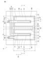
- FIG. 2 is a schematic plan view of a portion of the pressure sensor element according to the first embodiment of the present disclosure excluding a membrane layer;
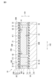
- FIG. 3 is a schematic end view of a portion of the pressure sensor element according to the first embodiment of the present disclosure, corresponding to the cross section BB in FIG.
- FIG. 3 is a schematic end view of a portion corresponding to the cross section AA of FIG. 2 in a modified example of the pressure sensor element according to the first embodiment of the present disclosure.
- FIG. 3 is a schematic end view of a portion corresponding to the cross section AA of FIG. 2 in a modified example of the pressure sensor element according to the first embodiment of the present disclosure.
- FIG. 3 is a schematic end view of a portion corresponding to the cross section AA of FIG. 2 in a modified example of the pressure sensor element according to the first embodiment of the present disclosure.
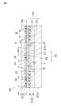
- FIG. 3 is a schematic end view of a portion of a pressure sensor element according to a second embodiment of the present disclosure, the portion corresponding to the cross section AA in FIG.
- FIG. 13 is a schematic plan view of a portion of a pressure sensor element according to a third embodiment of the present disclosure, excluding a membrane layer;
- FIG. 8 is a schematic end view of a portion of a pressure sensor element according to a third embodiment of the present disclosure, the portion corresponding to the CC cross section of FIG.
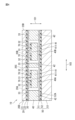
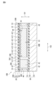
- Fig. 1 is a schematic end view of the pressure sensor element according to the first embodiment of the present disclosure.
- Fig. 2 is a schematic plan view of a portion of the pressure sensor element according to the first embodiment of the present disclosure excluding a membrane layer.
- Fig. 3 is a schematic end view of a portion of the pressure sensor element according to the first embodiment of the present disclosure corresponding to the B-B cross section in Fig. 2.
- Fig. 1 is a schematic end view of a portion corresponding to the A-A cross section in Fig. 2.
- the pressure sensor element 10 has a rectangular parallelepiped shape.
- the shape of the pressure sensor element 10 is not limited to a rectangular parallelepiped shape (a shape that is a rectangle when viewed from the thickness direction 101).
- the pressure sensor element 10 may have a polygonal shape other than a rectangle when viewed from the thickness direction 101, or may have a cylindrical shape.
- the pressure sensor element 10 includes a membrane layer 20, a first intermediate layer 30, a second intermediate layer 40, and a substrate layer 50.
- the membrane layer 20 comprises a membrane plate 21 and an insulating layer 22 laminated on the membrane plate 21.
- each of the diaphragm portions 20A, 20B may have a shape other than a rectangle, such as a square or a circle.
- the diaphragm portions 20A, 20B have the same shape and size as each other in a plan view, but the diaphragm portions 20A, 20B may have different shapes and sizes as well.
- the one main surface 20C and the side surface 20D of the membrane layer 20 may be covered with a protective film (not shown).
- the protective film is made of, for example, silicon dioxide (SiO 2 ) or silicon nitride (SiN).
- the first intermediate layer 30 includes a connection portion 31, an electrode portion 32, and a guard portion 33.
- the connection portion 31, the electrode portion 32, and the guard portion 33 will be described later.
- the side wall portion 42 is joined to the guard portion 33 of the first intermediate layer 30 and the conductive layer 51 of the substrate layer 50.
- internal spaces 40A and 40B are connected to each other by internal spaces 40C and 40E. Note that internal spaces 40A and 40B do not have to be connected to each other. Internal space 40D is connected to internal space 40A. Internal space 40E is connected to internal spaces 40A and 40B.
- the internal spaces 40A, 40B in which the movable part 41 is disposed are provided corresponding to each of the two diaphragm parts 20A, 20B.
- the pressure sensor element 10 has two internal spaces 40A, 40B in which the movable part 41 is disposed.
- the internal space 40A is a space surrounded by the side wall part 42, a part of the insulating layer 22 that is included in the diaphragm part 20A, and the conductive layer 51.
- the internal space 40A is a space surrounded by the side wall part 42, a part of the insulating layer 22 that is included in the diaphragm part 20B, and the conductive layer 51.
- the pressure sensor element 10 has multiple diaphragm parts, an internal space is provided corresponding to each of the multiple diaphragm parts.
- the number of diaphragm parts is not limited to two. In other words, the number of internal spaces in which the movable part 41 is arranged is not limited to two.
- the number of internal spaces in which the movable parts 41 are arranged is not limited to two. In other words, the number of movable parts 41 varies depending on the number of internal spaces in which the movable parts 41 are arranged. In other words, the number of movable parts 41 is not limited to two.
- Each movable portion 41 is provided away from the substrate layer 50 (specifically, the conductive layer 51 of the substrate layer 50) and the side wall portion 42.
- the second intermediate layer 40 is conductive and is formed of silicon (Si).
- the thickness of the side wall portion 42 is 50 ⁇ m
- the gap G1 between each movable portion 41 and the conductive layer 51 is 2 ⁇ m.
- the thickness of each movable portion 41 is thinner than the side wall portion 42 by the gap G1 between the movable portion 41 and the substrate layer 50.
- the material forming the second intermediate layer 40 is not limited to silicon.
- the thickness of the side wall portion 42 is not limited to 50 ⁇ m.
- the gap G1 between each movable portion 41 and the conductive layer 51 is not limited to 2 ⁇ m.
- connection portion 31 and each electrode portion 32 is provided corresponding to each of the multiple internal spaces.
- One of the two connection portions 31 and one of the two electrode portions 32 are provided in the internal space 40A, and the other of the two connection portions 31 and the other of the two electrode portions 32 are provided in the internal space 40B.
- One of the two connection portions 31 and one of the two electrode portions 32 are joined to the diaphragm portion 20A.
- the other of the two connection portions 31 and the other of the two electrode portions 32 are joined to the diaphragm portion 20B.
- the movable parts are provided corresponding to each of the multiple internal spaces.
- the number of internal spaces is not limited to two.
- the number of connection parts 31 is not limited to two
- the number of electrode parts 32 is not limited to two.
- connection portion 31 and electrode portion 32 provided in the internal space 40A have the same configuration as the connection portion 31 and electrode portion 32 provided in the internal space 40B. Therefore, the configuration of the connection portion 31 and electrode portion 32 provided in the internal space 40A will be described below. The configuration of the connection portion 31 and electrode portion 32 provided in the internal space 40B will be omitted in principle and will be described only as necessary.
- connection portion 31 and the electrode portion 32 are located between the diaphragm portion 20A of the membrane layer 20 and the second intermediate layer 40 in the thickness direction 101.
- the connection portion 31 and the electrode portion 32 are joined to the diaphragm portion 20A of the insulating layer 22 of the membrane layer 20.
- connection portion 31 is joined to a support portion 411 provided on the movable portion 41 of the second intermediate layer 40.
- the support portion 411 is a convex portion provided on the movable portion 41, and protrudes in the thickness direction 101 from the movable portion 41 toward the connection portion 31.
- the connection portion 31 is joined to the diaphragm portion 20A.
- the diaphragm portion 20A supports the movable portion 41 via the connection portion 31.
- the support portion 411 is the portion of the movable portion 41 that is supported by the diaphragm portion 20A.
- the support portion 411 is supported by the diaphragm portion 20A via the connection portion 31 at a position where the amount of displacement is maximum when pressure is applied to the diaphragm portion 20A.
- the amount of displacement is small at the outer edge of the rectangle. The greater the distance from that portion when viewed in the thickness direction 101, the greater the amount of displacement.
- the support portion 411 is supported by the diaphragm portion 20A at a position where the amount of displacement is maximum. In the first embodiment, both ends of the support portion 411 in the first direction 102 do not reach the ends of the diaphragm portion 20A in the first direction 102.
- the value obtained by dividing the length L1 (length in the first direction 102) of the long side of the rectangle in the plan view of the diaphragm portion 20A from the length L3 (length in the first direction 102) of the long side of the rectangle in the plan view of the support portion 411 is 0.1 or more and 0.75 or less.
- the value obtained by dividing the length L1 from the length L3 is 0.5 or more and 0.7 or less.
- the value obtained by dividing the length (length in the second direction 103) of the short side of the rectangle in the plan view of the diaphragm portion 20A (length in the second direction 103) from the length (length in the second direction 103) of the short side of the rectangle in the plan view of the support portion 411 is 0.05 or more and 0.5 or less.
- the value is 0.07 or more and 0.15 or less.
- the electrode portion 32 faces the movable portion 41 with a gap therebetween in the thickness direction 101.
- the gap G2 between the electrode portion 32 and the movable portion 41 is 0.2 ⁇ m.
- the gap G2 between the electrode portion 32 and the movable portion 41 is not limited to 0.2 ⁇ m.
- the electrode portion 32 when viewed from the thickness direction 101, the electrode portion 32 is arranged to surround the support portion 411.
- the electrode portion 32 provided in the internal space 40A and the electrode portion 32 provided in the internal space 40B are electrically connected via the communication portion 320.
- the electrode portion 32 provided in the internal space 40A can be electrically connected to the outside of the pressure sensor element 10 via the communication portion 321 and the terminal 61.
- the terminal 61 is for electrically connecting the electrode portion 32 to the outside of the pressure sensor element 10.
- the terminal 61 is exposed to the outside, similar to the terminal 62 described later.
- the communication portion 321 is supported by a first support wall portion (not shown) provided in the second intermediate layer 40.
- the first support wall portion is electrically connected to the electrode portion 32 via the communication portion 321.
- the first support wall portion is separated from the connection portion 31 and the guard portion 33, and is electrically insulated from the connection portion 31 and the guard portion 33.
- each of the movable parts 41 provided in the internal spaces 40A and 40B is electrically connected to the connection part 31 via the support part 411.
- the connection part 31 provided in the internal space 40A can be electrically connected to the outside of the pressure sensor element 10 via the communication part 311 and the terminal 62.
- the connection part 31 provided in the internal space 40B can be electrically connected to the outside of the pressure sensor element 10 via the communication part 312 and the terminal 62.
- the terminal 62 is for electrically connecting the movable part 41 to the outside of the pressure sensor element 10.
- the terminal 62 is exposed to the outside by an opening 20E formed in the membrane layer 20 (see FIG. 3).
- the communication parts 311 and 312 are supported by the second support wall part 43 provided in the second intermediate layer 40.
- the second support wall part 43 is electrically connected to the connection part 31 via the communication parts 311 and 312.
- the second support wall portion 43 is separated from the electrode portion 32 and the guard portion 33 and is electrically insulated from the electrode portion 32 and the guard portion 33.
- a capacitor having a gap G2 is formed between the electrode portion 32 and the movable portion 41 in each of the internal spaces 40A and 40B, as shown in FIG. 1.
- the diaphragm portions 20A and 20B of the membrane layer 20 bend in the thickness direction 101 toward the substrate layer 50.
- the diaphragm portions 20A and 20B of the membrane layer 20 are displaced in the thickness direction 101 toward the substrate layer 50.
- the movable portion 41 and the electrode portion 32 joined to the diaphragm portions 20A and 20B move.
- the movable part 41 including the support part 411 is supported by the diaphragm parts 20A and 20B at a position where the amount of displacement when pressure acts on the diaphragm part 20A is maximum.
- the electrode part 32 is joined to the membrane layer 20 around the support part 411. In other words, the electrode part 32 is joined to the membrane layer 20 at a position where the amount of displacement when pressure acts on the diaphragm part 20A is not maximum. Therefore, when the membrane layer 20 bends, the amount of movement of the movable part 41 in the thickness direction 101 is greater than the amount of movement of the electrode part 32 in the thickness direction 101.
- the diaphragm portions 20A, 20B of the membrane layer 20 do not function as electrodes that form capacitance for pressure detection.
- the electrode portion 32 of the first intermediate layer 30 and the movable portion 41 of the second intermediate layer 40 function as electrodes that form capacitance for pressure detection.
- the movable portion 41 moves due to the displacement of the diaphragm portions 20A, 20B when pressure is applied. The pressure change is detected by the change in capacitance between the electrode portion 32 and the movable portion 41 at this time.
- the movable portion 41 is located in the internal spaces 40A, 40B.
- the electrode portion 32 faces the movable portion 41 with a gap in the thickness direction 101 between the diaphragm portions 20A, 20B and the second intermediate layer 40.
- the electrode portion 32 is also located in the internal spaces 40A, 40B. This reduces the adhesion of foreign matter such as water from the outside to the electrode part 32 and the movable part 41, and reduces the effects of disturbances such as electromagnetic waves on the electrode part 32 and the movable part 41. As a result, it is possible to suppress a decrease in the accuracy of pressure detection.
- both the electrode portion 32 and the guard portion 33 in the first intermediate layer 30 are bonded to the membrane layer 20. Therefore, in the manufacturing process of the pressure sensor element 10, the lamination process of the membrane layer 20 and the first intermediate layer 30 can be performed more easily than a lamination process in which one of the electrode portion 32 and the guard portion 33 is bonded to the membrane layer 20 while the other is not bonded to the membrane layer 20.
- the diaphragm portions 20A and 20B support the movable portion 41 at a position where the amount of displacement when pressure acts on the diaphragm portions 20A and 20B is maximum. Therefore, the amount of movement of the movable portion 41 when pressure acts on the diaphragm portions 20A and 20B can be increased. As a result, the change in distance between the movable portion 41 and the electrode portion 32 can be increased, thereby improving the accuracy of pressure detection.
- the internal spaces 40A and 40B may be sealed spaces. In that case, it is possible to prevent foreign matter from adhering to the electrode portion 32 and the movable portion 41.
- the amount of displacement of the diaphragm portion is greatest at a point in the center of the square, and the amount of displacement decreases with increasing distance from the center.
- the amount of displacement of the diaphragm portions 20A, 20B is greatest at the center in the direction along the short side of the rectangle, and the amount of displacement decreases with increasing distance from the center.
- This portion with the greatest amount of displacement extends along the long side of the rectangle.
- the portion with the greatest amount of displacement of the diaphragm portions 20A, 20B is a line, not a point. That is, in a configuration in which the diaphragm portions 20A and 20B are rectangular when viewed from the thickness direction 101, the area in which the displacement of the diaphragm portions 20A and 20B is constant can be made larger than in a configuration in which the diaphragm portions are square when viewed from the thickness direction 101.
- the movable part 41 When the movable part 41 is supported in an area where the displacement of the diaphragm parts 20A and 20B is constant, the movement of the movable part 41 accompanying the displacement of the diaphragm parts 20A and 20B is stabilized. As a result, the change in distance between the movable part 41 and the electrode part 32 can be stabilized, and the deterioration of the accuracy of pressure detection can be suppressed.
- the area where the displacement of the diaphragm parts 20A and 20B is constant can be made larger than in a configuration in which the diaphragm parts 20A and 20B are square when viewed from the thickness direction 101.
- the support position of the support part relative to the diaphragm part may deviate from the correct position.
- the displacement of the movable part when pressure acts on the diaphragm part may differ from the intended displacement.
- the support part is formed in the center of the square diaphragm part, as in the pressure sensor element disclosed in Patent Document 1, the following problem may occur.
- the displacement of the movable part when pressure acts on the diaphragm part may not be the intended displacement (displacement in the thickness direction), but may be a displacement in a direction inclined relative to the thickness direction. This may result in a decrease in the accuracy of pressure detection.
- the accuracy of pressure detection may decrease regardless of the direction of the positional deviation.
- the support portion 411 has a linear shape extending along the long side direction of the diaphragm portions 20A, 20B, which are rectangular when viewed from the thickness direction 101.
- the displacement of the movable portion 41 when pressure acts on the diaphragm portions 20A, 20B is reduced to a displacement in a direction inclined relative to the thickness direction 101.
- the support portion is formed in the center of the rectangular diaphragm portion, it is possible to suppress a decrease in the accuracy of pressure detection depending on the direction of positional shift.
- the value obtained by dividing the length of the short side from the length of the long side of the diaphragm portions 20A and 20B, which are rectangular when viewed in the thickness direction 101, is 2 or more.
- the long side of the rectangle is longer for the same area than in a configuration in which the divided value is less than 2. Therefore, according to the first embodiment, the portion of the diaphragm portions 20A and 20B with the largest amount of displacement (the portion extending along the long side of the rectangle) can be made larger.
- the value obtained by dividing the length of the short side from the length of the long side of the diaphragm portion, which is rectangular when viewed in the thickness direction 101, may be 3 or more.
- the long side of the rectangle will be longer for the same area than in a configuration in which the divided value is less than 3. Therefore, according to the first embodiment, the portion of the diaphragm portions 20A, 20B with the largest amount of displacement (the portion extending along the long side of the rectangle) can be made larger.
- the multiple diaphragm parts 20A, 20B are arranged along the short side direction of the rectangle so that the long sides of the rectangles of two adjacent diaphragm parts 20A, 20B face each other.
- This makes it possible to reduce the difference in length between the long side and the short side of the multiple diaphragm parts 20A, 20B as a whole, compared to a single rectangular diaphragm part having the same area as the total area of the multiple diaphragm parts 20A, 20B when viewed from the thickness direction 101.
- the shape of the pressure sensor element 10 can be made closer to a stable square shape.
- the pressure sensor element 10 can be easily mounted on the substrate, and warping of the pressure sensor element 10 can be reduced.
- an internal space with a larger volume is formed compared to a configuration in which the multiple internal spaces 40A, 40B are not connected to each other. This makes it possible to suppress manufacturing variations in the pressure sensor element 10 caused by the internal pressure of the internal space. As a result, it is possible to reduce variations in the pressure detection characteristics between the multiple manufactured pressure sensor elements 10.
- Fig. 4 is a schematic end view of a portion corresponding to the A-A cross section in Fig. 2 in a modified example of the pressure sensor element according to the first embodiment of the present disclosure.
- Fig. 5 is a schematic end view of a portion corresponding to the A-A cross section in Fig. 2 in a modified example of the pressure sensor element according to the first embodiment of the present disclosure. Note that the modified examples described below will be described as modified examples of the pressure sensor element according to the first embodiment, but may also be adopted as modified examples of the pressure sensor elements according to the second and third embodiments.
- each layer of the pressure sensor element 10 is not limited to the configuration shown in Figures 1 to 3.
- the pressure sensor element 10 may include an insulating layer 70 laminated on at least a portion of the upper surface of the movable portion 41 except for the portion where the support portion 411 is provided.
- the material forming the insulating layer 70 is, for example, silicon dioxide (SiO 2 ) or silicon nitride (SiN).
- the material forming the insulating layer 70 may be a material other than silicon dioxide (SiO 2 ) or silicon nitride (SiN).
- the side wall portion 42 of the second intermediate layer 40 of the pressure sensor element 10 may include a conductive conductive layer 44 and an insulating insulating layer 45 laminated on the conductive layer 44 and bonded to the first intermediate layer 30.
- the substrate layer 50 of the pressure sensor element 10 may not include the conductive layer 51 and the insulating layer 52, and may be composed of only the substrate 53.
- the terminals 61 and 62 may be provided on the membrane plate 21.
- the membrane plate 21 includes plates 211, 212, and 213 that are insulated from one another.
- the terminal 61 is provided on the plate 212.
- the terminal 62 is provided on the plate 211.
- the connection portion 31 is electrically connected to the terminal 62 via a through hole 22A formed in the insulating layer 22.
- the electrode portion 32 is electrically connected to the terminal 61 via a through hole 22B formed in the insulating layer 22. Note that the connection portions 31 shown in multiple locations in FIG. 5 are connected to each other at different positions in the depth direction of the paper surface of FIG. 5.
- a terminal 63 may be further provided.
- the terminal 63 is provided on the plate 213.
- the guard portion 33 is electrically connected to the terminal 63 via a through hole 22C formed in the insulating layer 22.
- the pressure sensor element 10 of the modified example shown in FIG. 5 has one each of the diaphragm portion 20A, the internal space 40A, the movable portion 41, the connection portion 31, and the electrode portion 32. This is consistent with the above explanation that the number of each of the internal space 40A, the movable portion 41, the connection portion 31, and the electrode portion 32 is not limited to two.
- Second Embodiment 6 is a schematic end view of a portion of the pressure sensor element according to the second embodiment of the present disclosure, which corresponds to the A-A cross section in FIG. 2.
- the pressure sensor element 10A according to the second embodiment differs from the pressure sensor element 10 according to the first embodiment in that the electrode portion is separated from the diaphragm portion and that the electrode portion is supported by the side wall portion.
- the differences from the first embodiment will be described below. Points in common with the pressure sensor element 10 according to the first embodiment are given the same reference numerals, and explanations thereof will be omitted in principle, and will be described only when necessary.
- the pressure sensor element 10A shown in FIG. 6 has one each of a diaphragm portion 20A, an internal space 40A, a movable portion 41, a connection portion 31, and an electrode portion 32, similar to the pressure sensor element 10 shown in FIG. 5.
- the pressure sensor element 10A also has a conductive layer 44 and an insulating layer 45, similar to the side wall portion 42 of the second intermediate layer 40 of the pressure sensor element 10 shown in FIG. 5.
- the electrode portion 32 is not joined to the diaphragm portion 20A of the membrane layer 20.
- the insulating layer 22 is not formed directly above the electrode portion 32, and the electrode portion 32 faces the membrane plate 21 of the membrane layer 20 in the thickness direction 101 via a gap 22D.
- the gap 22D is in communication with the internal space 40A via the gap 30A between the connection portion 31 and the electrode portion 32.
- the electrode portion 32 has a portion that faces the movable portion 41 with a gap therebetween in the thickness direction 101, and a portion that does not face the movable portion 41 in the thickness direction 101.
- the electrode portion 32 is joined to the insulating layer 45 of the side wall portion 42 in the portion that does not face the movable portion 41 in the thickness direction 101. In this way, the electrode portion 32 is supported by the side wall portion 42.
- connection portion 31 and the guard portion 33 are joined to the insulating layer 22 of the membrane layer 20, similar to the pressure sensor element 10 according to the first embodiment.
- the terminals 61 and 62 are exposed to the outside through an opening 20F formed in the membrane layer 20.
- the terminal 63 is provided on the membrane plate 21.
- the pressure sensor element 10A shown in FIG. 6 further includes a terminal 64.
- the terminal 64 is provided on the guard portion 33 of the first intermediate layer 30.
- the terminal 64 is exposed to the outside through an opening 20G formed in the membrane layer 20.
- the movable part 41 supported by the diaphragm part 20A moves in the thickness direction 101 due to the displacement of the diaphragm part 20A.
- the electrode part 32 which is separated from the diaphragm part 20A, does not move due to the displacement of the diaphragm part 20A. Therefore, when the movable part 41 moves, the electrode part 32 and the movable part 41 are maintained parallel to each other, and the deterioration of the accuracy of the pressure detection is suppressed.
- the electrode part 32 bends together with the diaphragm part 20A. Therefore, the parallelism between the electrode part 32 and the movable part 41 is not maintained, and there is a risk of the accuracy of the pressure detection being reduced.
- the deterioration of the accuracy of the pressure detection can be suppressed more than in the configuration in which the electrode part 32 is joined to the diaphragm part 20A.
- Fig. 7 is a schematic plan view of a portion of the pressure sensor element according to the third embodiment of the present disclosure excluding the membrane layer.
- Fig. 8 is a schematic end view of a portion of the pressure sensor element according to the third embodiment of the present disclosure corresponding to the CC cross section of Fig. 7.
- the pressure sensor element 10B according to the third embodiment differs from the pressure sensor element 10 according to the first embodiment in that the movable portion 41 includes a plurality of support portions 412. Differences from the first embodiment will be described below. Points in common with the pressure sensor element 10 according to the first embodiment are given the same reference numerals, and descriptions thereof will be omitted in principle, and will be described only when necessary.
- the movable part 41 has multiple support parts 412 instead of one support part 411.
- Each of the multiple support parts 412 is a convex part provided on the movable part 41, and protrudes in the thickness direction 101 from the movable part 41 toward the connection part 31.
- Each of the multiple support parts 412 is joined to the connection part 31.
- the diaphragm parts 20A, 20B support the movable part 41 via the connection part 31 and the multiple support parts 412.
- each of the multiple support parts 412 is a part of the movable part 41 that is supported by the diaphragm parts 20A, 20B.
- the multiple support parts 412 are supported by the diaphragm parts 20A, 20B via the connection parts 31 at positions where the amount of displacement is maximum when pressure acts on the diaphragm parts 20A, 20B, similar to the support parts 411 of the pressure sensor element 10 according to the first embodiment.
- the multiple support portions 412 are arranged at intervals along the long side direction (first direction 102) of the diaphragm portions 20A and 20B, which are rectangular when viewed from the thickness direction 101.
- one movable part 41 is arranged in each of the internal spaces 40A and 40B.
- multiple movable parts 41 may be arranged in each of the internal spaces 40A and 40B.
- each of the multiple movable parts 41 may have one support part 412 or multiple support parts 412.
- three movable parts 41 may be arranged in the internal space 40A.
- each of the three movable parts 41 may have one support part 412 or multiple support parts 412.
- the number of support parts 412 provided for each of the multiple movable parts 41 arranged in the internal spaces 40A and 40B may be different. For example, if three movable parts 41 are arranged in the internal space 40A, one of the three movable parts 41 may have multiple support parts 412, and the remaining two of the three movable parts 41 may have one support part 412.
- multiple support parts 412 are arranged at intervals from each other. Therefore, compared to a configuration in which one support part 411 extends linearly, the diaphragm parts 20A and 20B supporting the support parts 412 are more likely to bend. As a result, the movable part 41 is more likely to move, improving the accuracy of pressure detection.
- multiple support parts 412 are arranged along the long side direction. Therefore, similar to a configuration in which one support part 411 extends along the long side direction, even if the support position of the support part 412 with respect to the diaphragm part 20A is shifted from the center in the long side direction, tilting and displacement of the movable part 41 is suppressed.
- the diaphragm portion 20A is made more flexible than in that configuration, thereby improving the accuracy of pressure detection.
- the pressure sensor element described above can also be expressed as follows:
- a pressure sensor element having a diaphragm portion; a substrate layer facing the membrane layer with a gap therebetween in a thickness direction; a first intermediate layer positioned between the membrane layer and the substrate layer; a second intermediate layer located between the first intermediate layer and the substrate layer; The first intermediate layer is an electrode portion located between the diaphragm portion and the second intermediate layer; a guard portion that is joined to a portion of the membrane layer different from the diaphragm portion and is electrically insulated from the electrode portion, The second intermediate layer is a sidewall portion joined to the substrate layer and the guard portion; the conductive movable portion is provided in an internal space partitioned by the diaphragm portion, the substrate layer, and the side wall portion, away from the substrate layer and the side wall portion, faces the electrode portion with a gap in the thickness direction, and is supported by the diaphragm portion and moves as the diaphragm portion is displaced.
- the electrode portion may be joined to the diaphragm portion.
- the electrode portion may be separated from the diaphragm portion, and may be supported by the side wall portion at a portion not facing the movable portion in the thickness direction.
- the diaphragm portion may support the movable portion at a position where a displacement amount is maximum when pressure acts on the diaphragm portion.
- the internal space may be an enclosed space.
- the diaphragm portion When viewed in the thickness direction, the diaphragm portion may be rectangular.
- a support portion which is a portion of the movable portion supported by the diaphragm portion may have a linear shape extending along a long side direction of the diaphragm portion which is rectangular when viewed in the thickness direction.
- the movable portion may include a plurality of support portions each of which is supported by the diaphragm portion, The plurality of support portions may be arranged at intervals from one another along a long side direction of the diaphragm portion which is rectangular when viewed in the thickness direction.
- the diaphragm portion which is rectangular when viewed in the thickness direction, may have a value obtained by dividing the length of a short side by the length of a long side.
- the diaphragm portion which is rectangular when viewed in the thickness direction, may have a value obtained by dividing the length of a short side by the length of a long side.
- the membrane layer may include a plurality of the diaphragm portions,
- the internal space may be provided in a plurality of spaces corresponding to the plurality of diaphragm portions
- the first intermediate layer may include a plurality of the electrode portions provided corresponding to the plurality of internal spaces
- the second intermediate layer may include a plurality of the movable parts provided corresponding to each of the plurality of internal spaces
- the movable portion may be provided apart from the substrate layer and the side wall portion, may face the electrode portion at an interval in the thickness direction, and may be supported by the diaphragm portion and may move as the diaphragm portion is displaced.
- the plurality of diaphragm portions each of which is rectangular when viewed in the thickness direction, may be arranged along the short side direction of the rectangle such that the long sides of the rectangles of two adjacent diaphragm portions face each other.
- the internal spaces may be in communication with each other.
- the pressure sensor may have only some of the features of the pressure sensor disclosed herein.
- the pressure sensor element may not have the characteristic feature of having a movable part in an internal space partitioned by the diaphragm part, the substrate layer, and the sidewall part, but may have the characteristic feature of having a rectangular diaphragm part when viewed in the thickness direction.
- one aspect of the pressure sensor element is, for example, as shown in (13) below.
- a pressure sensor element having a diaphragm portion; a substrate layer facing the membrane layer with a gap therebetween in a thickness direction; an intermediate layer located between the membrane layer and the substrate layer; the membrane layer has an electrode portion on the diaphragm portion,
- the intermediate layer is a sidewall portion joined to the substrate layer and the membrane layer; a conductive movable portion that is provided away from the side wall portion, faces the electrode portion with a gap in the thickness direction, is supported by a portion of the diaphragm portion different from the electrode portion, and moves when the diaphragm portion is displaced, When viewed in the thickness direction, the diaphragm portion has a rectangular shape.
- the first intermediate layer 30 is included in the membrane layer 20.
- the second intermediate layer 40 is an example of an intermediate layer.
- the pressure sensor element (13) may have the features of (1) to (12) above. However, the feature of (6) is included in (13).
Landscapes
- Physics & Mathematics (AREA)
- General Physics & Mathematics (AREA)
- Chemical & Material Sciences (AREA)
- Analytical Chemistry (AREA)
- Measuring Fluid Pressure (AREA)
Abstract
L'invention concerne un élément capteur de pression avec lequel il est possible de supprimer une diminution de la précision de détection de pression. L'élément capteur de pression comprend : une couche de membrane ayant une partie diaphragme ; une couche de substrat faisant face à la couche de membrane à travers un espace dans une direction d'épaisseur ; une première couche intermédiaire positionnée entre la couche de membrane et la couche de substrat ; et une seconde couche intermédiaire positionnée entre la première couche intermédiaire et la couche de substrat. La première couche intermédiaire comprend : une partie d'électrode positionnée entre la partie de diaphragme et la première couche intermédiaire ; et une partie de protection jointe à une partie de la couche de membrane différente de la partie de diaphragme et isolée électriquement de la partie d'électrode. La seconde couche intermédiaire comprend : des parties de paroi latérale reliées à la couche de substrat et à la partie de protection ; et une partie mobile électroconductrice qui est disposée à distance de la couche de substrat et des parties de paroi latérale dans un espace interne délimité par la partie de diaphragme, la couche de substrat et les parties de paroi latérale, fait face à la partie d'électrode à travers un espace dans la direction de l'épaisseur, est supportée par la partie de diaphragme, et se déplace en réponse au déplacement de la partie de diaphragme.
Priority Applications (2)
| Application Number | Priority Date | Filing Date | Title |
|---|---|---|---|
| CN202480032017.7A CN121175545A (zh) | 2023-06-07 | 2024-05-13 | 压力传感器元件 |
| US19/371,274 US20260049878A1 (en) | 2023-06-07 | 2025-10-28 | Pressure sensor device |
Applications Claiming Priority (2)
| Application Number | Priority Date | Filing Date | Title |
|---|---|---|---|
| JP2023094110 | 2023-06-07 | ||
| JP2023-094110 | 2023-06-07 |
Related Child Applications (1)
| Application Number | Title | Priority Date | Filing Date |
|---|---|---|---|
| US19/371,274 Continuation US20260049878A1 (en) | 2023-06-07 | 2025-10-28 | Pressure sensor device |
Publications (1)
| Publication Number | Publication Date |
|---|---|
| WO2024252855A1 true WO2024252855A1 (fr) | 2024-12-12 |
Family
ID=93795270
Family Applications (1)
| Application Number | Title | Priority Date | Filing Date |
|---|---|---|---|
| PCT/JP2024/017650 Ceased WO2024252855A1 (fr) | 2023-06-07 | 2024-05-13 | Élément capteur de pression |
Country Status (3)
| Country | Link |
|---|---|
| US (1) | US20260049878A1 (fr) |
| CN (1) | CN121175545A (fr) |
| WO (1) | WO2024252855A1 (fr) |
Citations (5)
| Publication number | Priority date | Publication date | Assignee | Title |
|---|---|---|---|---|
| US20150198493A1 (en) * | 2014-01-14 | 2015-07-16 | Robert Bosch Gmbh | Micromechanical pressure sensor device and corresponding manufacturing method |
| JP2015137949A (ja) * | 2014-01-22 | 2015-07-30 | セイコーエプソン株式会社 | 物理量センサー、高度計、電子機器および移動体 |
| JP2015213967A (ja) * | 2014-05-08 | 2015-12-03 | セイコーエプソン株式会社 | Mems構造体の製造方法およびmems構造体 |
| US20180335358A1 (en) * | 2015-06-29 | 2018-11-22 | Goertek.Inc | Mems pressure sensing element |
| JP2020153779A (ja) * | 2019-03-19 | 2020-09-24 | 株式会社東芝 | 圧力センサ |
-
2024
- 2024-05-13 CN CN202480032017.7A patent/CN121175545A/zh active Pending
- 2024-05-13 WO PCT/JP2024/017650 patent/WO2024252855A1/fr not_active Ceased
-
2025
- 2025-10-28 US US19/371,274 patent/US20260049878A1/en active Pending
Patent Citations (5)
| Publication number | Priority date | Publication date | Assignee | Title |
|---|---|---|---|---|
| US20150198493A1 (en) * | 2014-01-14 | 2015-07-16 | Robert Bosch Gmbh | Micromechanical pressure sensor device and corresponding manufacturing method |
| JP2015137949A (ja) * | 2014-01-22 | 2015-07-30 | セイコーエプソン株式会社 | 物理量センサー、高度計、電子機器および移動体 |
| JP2015213967A (ja) * | 2014-05-08 | 2015-12-03 | セイコーエプソン株式会社 | Mems構造体の製造方法およびmems構造体 |
| US20180335358A1 (en) * | 2015-06-29 | 2018-11-22 | Goertek.Inc | Mems pressure sensing element |
| JP2020153779A (ja) * | 2019-03-19 | 2020-09-24 | 株式会社東芝 | 圧力センサ |
Also Published As
| Publication number | Publication date |
|---|---|
| US20260049878A1 (en) | 2026-02-19 |
| CN121175545A (zh) | 2025-12-19 |
Similar Documents
| Publication | Publication Date | Title |
|---|---|---|
| CN104203806B (zh) | 用于微机电的测量变换器的膜片装置和用于制造膜片装置的方法 | |
| KR102432312B1 (ko) | Mems 마이크로폰 | |
| CN111698624B (zh) | Mems器件以及用于制造mems器件的方法 | |
| US9264814B2 (en) | Microphone | |
| US9816881B2 (en) | Single diaphragm transducer structure | |
| US20150041930A1 (en) | Acoustic transducer | |
| US9414139B2 (en) | Acoustic transducer | |
| US7277563B2 (en) | Capacitive micro pressure sensing member and fingerprint sensor using the same | |
| KR20150047046A (ko) | 음향 변환기 및 패키지 모듈 | |
| US20210061651A1 (en) | Mems microphone | |
| US10524058B2 (en) | Piezoelectric microphone | |
| KR101068341B1 (ko) | 용량형 역학량 센서 | |
| JP2008244752A (ja) | 静電型圧力変換器 | |
| US20260049878A1 (en) | Pressure sensor device | |
| US20200024134A1 (en) | Mems devices and processes | |
| JP2007225344A (ja) | 圧力センサ | |
| WO2025253781A1 (fr) | Élément de détection de pression | |
| WO2024257458A1 (fr) | Élément capteur de pression | |
| KR100941893B1 (ko) | 커패시터형 실리콘 멤스 마이크로폰 | |
| US12139394B2 (en) | Multiple layer electrode transducers | |
| JP4775412B2 (ja) | 半導体物理量センサ | |
| US12158384B2 (en) | Pressure sensor | |
| CN114390418A (zh) | 微机电系统电极形成方法 | |
| KR101816253B1 (ko) | 음성전달장치 및 그 제조방법 | |
| US12203824B2 (en) | Sensor |
Legal Events
| Date | Code | Title | Description |
|---|---|---|---|
| 121 | Ep: the epo has been informed by wipo that ep was designated in this application |
Ref document number: 24819092 Country of ref document: EP Kind code of ref document: A1 |
|
| WWE | Wipo information: entry into national phase |
Ref document number: CN2024800320177 Country of ref document: CN |
|
| NENP | Non-entry into the national phase |
Ref country code: DE |
|
| 122 | Ep: pct application non-entry in european phase |
Ref document number: 24819092 Country of ref document: EP Kind code of ref document: A1 |