WO2024252855A1 - 圧力センサ素子 - Google Patents
圧力センサ素子 Download PDFInfo
- Publication number
- WO2024252855A1 WO2024252855A1 PCT/JP2024/017650 JP2024017650W WO2024252855A1 WO 2024252855 A1 WO2024252855 A1 WO 2024252855A1 JP 2024017650 W JP2024017650 W JP 2024017650W WO 2024252855 A1 WO2024252855 A1 WO 2024252855A1
- Authority
- WO
- WIPO (PCT)
- Prior art keywords
- diaphragm
- pressure sensor
- sensor element
- layer
- thickness direction
- Prior art date
- Legal status (The legal status is an assumption and is not a legal conclusion. Google has not performed a legal analysis and makes no representation as to the accuracy of the status listed.)
- Ceased
Links
Images



Classifications
-
- G—PHYSICS
- G01—MEASURING; TESTING
- G01L—MEASURING FORCE, STRESS, TORQUE, WORK, MECHANICAL POWER, MECHANICAL EFFICIENCY, OR FLUID PRESSURE
- G01L9/00—Measuring steady of quasi-steady pressure of fluid or fluent solid material by electric or magnetic pressure-sensitive elements; Transmitting or indicating the displacement of mechanical pressure-sensitive elements, used to measure the steady or quasi-steady pressure of a fluid or fluent solid material, by electric or magnetic means
- G01L9/0041—Transmitting or indicating the displacement of flexible diaphragms
- G01L9/0072—Transmitting or indicating the displacement of flexible diaphragms using variations in capacitance
-
- G—PHYSICS
- G01—MEASURING; TESTING
- G01L—MEASURING FORCE, STRESS, TORQUE, WORK, MECHANICAL POWER, MECHANICAL EFFICIENCY, OR FLUID PRESSURE
- G01L19/00—Details of, or accessories for, apparatus for measuring steady or quasi-steady pressure of a fluent medium insofar as such details or accessories are not special to particular types of pressure gauges
- G01L19/0061—Electrical connection means
-
- G—PHYSICS
- G01—MEASURING; TESTING
- G01L—MEASURING FORCE, STRESS, TORQUE, WORK, MECHANICAL POWER, MECHANICAL EFFICIENCY, OR FLUID PRESSURE
- G01L19/00—Details of, or accessories for, apparatus for measuring steady or quasi-steady pressure of a fluent medium insofar as such details or accessories are not special to particular types of pressure gauges
- G01L19/06—Means for preventing overload or deleterious influence of the measured medium on the measuring device or vice versa
- G01L19/0627—Protection against aggressive medium in general
- G01L19/0654—Protection against aggressive medium in general against moisture or humidity
-
- G—PHYSICS
- G01—MEASURING; TESTING
- G01L—MEASURING FORCE, STRESS, TORQUE, WORK, MECHANICAL POWER, MECHANICAL EFFICIENCY, OR FLUID PRESSURE
- G01L9/00—Measuring steady of quasi-steady pressure of fluid or fluent solid material by electric or magnetic pressure-sensitive elements; Transmitting or indicating the displacement of mechanical pressure-sensitive elements, used to measure the steady or quasi-steady pressure of a fluid or fluent solid material, by electric or magnetic means
-
- G—PHYSICS
- G01—MEASURING; TESTING
- G01L—MEASURING FORCE, STRESS, TORQUE, WORK, MECHANICAL POWER, MECHANICAL EFFICIENCY, OR FLUID PRESSURE
- G01L9/00—Measuring steady of quasi-steady pressure of fluid or fluent solid material by electric or magnetic pressure-sensitive elements; Transmitting or indicating the displacement of mechanical pressure-sensitive elements, used to measure the steady or quasi-steady pressure of a fluid or fluent solid material, by electric or magnetic means
- G01L9/0041—Transmitting or indicating the displacement of flexible diaphragms
- G01L9/0042—Constructional details associated with semiconductive diaphragm sensors, e.g. etching, or constructional details of non-semiconductive diaphragms
- G01L9/0044—Constructional details of non-semiconductive diaphragms
-
- G—PHYSICS
- G01—MEASURING; TESTING
- G01L—MEASURING FORCE, STRESS, TORQUE, WORK, MECHANICAL POWER, MECHANICAL EFFICIENCY, OR FLUID PRESSURE
- G01L9/00—Measuring steady of quasi-steady pressure of fluid or fluent solid material by electric or magnetic pressure-sensitive elements; Transmitting or indicating the displacement of mechanical pressure-sensitive elements, used to measure the steady or quasi-steady pressure of a fluid or fluent solid material, by electric or magnetic means
- G01L9/0041—Transmitting or indicating the displacement of flexible diaphragms
- G01L9/0072—Transmitting or indicating the displacement of flexible diaphragms using variations in capacitance
- G01L9/0073—Transmitting or indicating the displacement of flexible diaphragms using variations in capacitance using a semiconductive diaphragm
Definitions
- This disclosure relates to a pressure sensor element that detects pressure.
- the pressure sensor element disclosed in Patent Document 1 comprises a diaphragm that is square in plan view, a support portion provided in the center of the square diaphragm, and a movable portion supported by the support portion. As described in detail below, pressure changes are detected by changes in the capacitance between the movable portion and the diaphragm.
- the pressure sensor element disclosed in Patent Document 2 comprises a membrane plate that is displaced by the action of pressure, and a base electrode that faces the membrane plate.
- the membrane plate bends so as to approach the base electrode. This increases the capacitance between the membrane plate and the base electrode. The pressure acting on the membrane plate is detected based on the increase in capacitance.
- the membrane plate is covered with a passivation film. This prevents foreign matter such as water from adhering to the membrane plate.
- the diaphragm In the pressure sensor element disclosed in Patent Document 1, the diaphragm is exposed to the outside. Therefore, there is a risk that foreign matter such as water may adhere to the diaphragm, and that the diaphragm may be affected by external disturbances such as electromagnetic waves from the outside.
- the diaphragm is an electrode that forms electrostatic capacitance for pressure detection. Therefore, when the potential of the diaphragm changes due to the adhesion of foreign matter or the influence of external disturbances as described above, the electrostatic capacitance between the movable part changes. This may result in a decrease in the accuracy of pressure detection.
- the passivation film prevents foreign matter from adhering to the membrane plate.
- the membrane plate is an electrode that forms electrostatic capacitance for pressure detection. Therefore, if foreign matter adheres to the passivation film, there is a risk that a parasitic capacitance will be formed between the foreign matter and the membrane plate. This parasitic capacitance may reduce the accuracy of pressure detection.
- the present disclosure provides a pressure sensor element that can suppress deterioration in the accuracy of pressure detection.
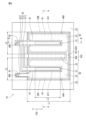
- FIG. 2 is a schematic plan view of a portion of the pressure sensor element according to the first embodiment of the present disclosure excluding a membrane layer;
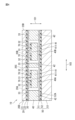
- FIG. 3 is a schematic end view of a portion of the pressure sensor element according to the first embodiment of the present disclosure, corresponding to the cross section BB in FIG.
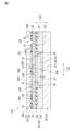
- FIG. 3 is a schematic end view of a portion corresponding to the cross section AA of FIG. 2 in a modified example of the pressure sensor element according to the first embodiment of the present disclosure.
- FIG. 3 is a schematic end view of a portion corresponding to the cross section AA of FIG. 2 in a modified example of the pressure sensor element according to the first embodiment of the present disclosure.
- FIG. 3 is a schematic end view of a portion corresponding to the cross section AA of FIG. 2 in a modified example of the pressure sensor element according to the first embodiment of the present disclosure.
- FIG. 3 is a schematic end view of a portion of a pressure sensor element according to a second embodiment of the present disclosure, the portion corresponding to the cross section AA in FIG.
- FIG. 13 is a schematic plan view of a portion of a pressure sensor element according to a third embodiment of the present disclosure, excluding a membrane layer;
- FIG. 8 is a schematic end view of a portion of a pressure sensor element according to a third embodiment of the present disclosure, the portion corresponding to the CC cross section of FIG.
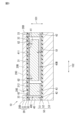
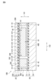
- Fig. 1 is a schematic end view of the pressure sensor element according to the first embodiment of the present disclosure.
- Fig. 2 is a schematic plan view of a portion of the pressure sensor element according to the first embodiment of the present disclosure excluding a membrane layer.
- Fig. 3 is a schematic end view of a portion of the pressure sensor element according to the first embodiment of the present disclosure corresponding to the B-B cross section in Fig. 2.
- Fig. 1 is a schematic end view of a portion corresponding to the A-A cross section in Fig. 2.
- the pressure sensor element 10 has a rectangular parallelepiped shape.
- the shape of the pressure sensor element 10 is not limited to a rectangular parallelepiped shape (a shape that is a rectangle when viewed from the thickness direction 101).
- the pressure sensor element 10 may have a polygonal shape other than a rectangle when viewed from the thickness direction 101, or may have a cylindrical shape.
- the pressure sensor element 10 includes a membrane layer 20, a first intermediate layer 30, a second intermediate layer 40, and a substrate layer 50.
- the membrane layer 20 comprises a membrane plate 21 and an insulating layer 22 laminated on the membrane plate 21.
- each of the diaphragm portions 20A, 20B may have a shape other than a rectangle, such as a square or a circle.
- the diaphragm portions 20A, 20B have the same shape and size as each other in a plan view, but the diaphragm portions 20A, 20B may have different shapes and sizes as well.
- the one main surface 20C and the side surface 20D of the membrane layer 20 may be covered with a protective film (not shown).
- the protective film is made of, for example, silicon dioxide (SiO 2 ) or silicon nitride (SiN).
- the first intermediate layer 30 includes a connection portion 31, an electrode portion 32, and a guard portion 33.
- the connection portion 31, the electrode portion 32, and the guard portion 33 will be described later.
- the side wall portion 42 is joined to the guard portion 33 of the first intermediate layer 30 and the conductive layer 51 of the substrate layer 50.
- internal spaces 40A and 40B are connected to each other by internal spaces 40C and 40E. Note that internal spaces 40A and 40B do not have to be connected to each other. Internal space 40D is connected to internal space 40A. Internal space 40E is connected to internal spaces 40A and 40B.
- the internal spaces 40A, 40B in which the movable part 41 is disposed are provided corresponding to each of the two diaphragm parts 20A, 20B.
- the pressure sensor element 10 has two internal spaces 40A, 40B in which the movable part 41 is disposed.
- the internal space 40A is a space surrounded by the side wall part 42, a part of the insulating layer 22 that is included in the diaphragm part 20A, and the conductive layer 51.
- the internal space 40A is a space surrounded by the side wall part 42, a part of the insulating layer 22 that is included in the diaphragm part 20B, and the conductive layer 51.
- the pressure sensor element 10 has multiple diaphragm parts, an internal space is provided corresponding to each of the multiple diaphragm parts.
- the number of diaphragm parts is not limited to two. In other words, the number of internal spaces in which the movable part 41 is arranged is not limited to two.
- the number of internal spaces in which the movable parts 41 are arranged is not limited to two. In other words, the number of movable parts 41 varies depending on the number of internal spaces in which the movable parts 41 are arranged. In other words, the number of movable parts 41 is not limited to two.
- Each movable portion 41 is provided away from the substrate layer 50 (specifically, the conductive layer 51 of the substrate layer 50) and the side wall portion 42.
- the second intermediate layer 40 is conductive and is formed of silicon (Si).
- the thickness of the side wall portion 42 is 50 ⁇ m
- the gap G1 between each movable portion 41 and the conductive layer 51 is 2 ⁇ m.
- the thickness of each movable portion 41 is thinner than the side wall portion 42 by the gap G1 between the movable portion 41 and the substrate layer 50.
- the material forming the second intermediate layer 40 is not limited to silicon.
- the thickness of the side wall portion 42 is not limited to 50 ⁇ m.
- the gap G1 between each movable portion 41 and the conductive layer 51 is not limited to 2 ⁇ m.
- connection portion 31 and each electrode portion 32 is provided corresponding to each of the multiple internal spaces.
- One of the two connection portions 31 and one of the two electrode portions 32 are provided in the internal space 40A, and the other of the two connection portions 31 and the other of the two electrode portions 32 are provided in the internal space 40B.
- One of the two connection portions 31 and one of the two electrode portions 32 are joined to the diaphragm portion 20A.
- the other of the two connection portions 31 and the other of the two electrode portions 32 are joined to the diaphragm portion 20B.
- the movable parts are provided corresponding to each of the multiple internal spaces.
- the number of internal spaces is not limited to two.
- the number of connection parts 31 is not limited to two
- the number of electrode parts 32 is not limited to two.
- connection portion 31 and electrode portion 32 provided in the internal space 40A have the same configuration as the connection portion 31 and electrode portion 32 provided in the internal space 40B. Therefore, the configuration of the connection portion 31 and electrode portion 32 provided in the internal space 40A will be described below. The configuration of the connection portion 31 and electrode portion 32 provided in the internal space 40B will be omitted in principle and will be described only as necessary.
- connection portion 31 and the electrode portion 32 are located between the diaphragm portion 20A of the membrane layer 20 and the second intermediate layer 40 in the thickness direction 101.
- the connection portion 31 and the electrode portion 32 are joined to the diaphragm portion 20A of the insulating layer 22 of the membrane layer 20.
- connection portion 31 is joined to a support portion 411 provided on the movable portion 41 of the second intermediate layer 40.
- the support portion 411 is a convex portion provided on the movable portion 41, and protrudes in the thickness direction 101 from the movable portion 41 toward the connection portion 31.
- the connection portion 31 is joined to the diaphragm portion 20A.
- the diaphragm portion 20A supports the movable portion 41 via the connection portion 31.
- the support portion 411 is the portion of the movable portion 41 that is supported by the diaphragm portion 20A.
- the support portion 411 is supported by the diaphragm portion 20A via the connection portion 31 at a position where the amount of displacement is maximum when pressure is applied to the diaphragm portion 20A.
- the amount of displacement is small at the outer edge of the rectangle. The greater the distance from that portion when viewed in the thickness direction 101, the greater the amount of displacement.
- the support portion 411 is supported by the diaphragm portion 20A at a position where the amount of displacement is maximum. In the first embodiment, both ends of the support portion 411 in the first direction 102 do not reach the ends of the diaphragm portion 20A in the first direction 102.
- the value obtained by dividing the length L1 (length in the first direction 102) of the long side of the rectangle in the plan view of the diaphragm portion 20A from the length L3 (length in the first direction 102) of the long side of the rectangle in the plan view of the support portion 411 is 0.1 or more and 0.75 or less.
- the value obtained by dividing the length L1 from the length L3 is 0.5 or more and 0.7 or less.
- the value obtained by dividing the length (length in the second direction 103) of the short side of the rectangle in the plan view of the diaphragm portion 20A (length in the second direction 103) from the length (length in the second direction 103) of the short side of the rectangle in the plan view of the support portion 411 is 0.05 or more and 0.5 or less.
- the value is 0.07 or more and 0.15 or less.
- the electrode portion 32 faces the movable portion 41 with a gap therebetween in the thickness direction 101.
- the gap G2 between the electrode portion 32 and the movable portion 41 is 0.2 ⁇ m.
- the gap G2 between the electrode portion 32 and the movable portion 41 is not limited to 0.2 ⁇ m.
- the electrode portion 32 when viewed from the thickness direction 101, the electrode portion 32 is arranged to surround the support portion 411.
- the electrode portion 32 provided in the internal space 40A and the electrode portion 32 provided in the internal space 40B are electrically connected via the communication portion 320.
- the electrode portion 32 provided in the internal space 40A can be electrically connected to the outside of the pressure sensor element 10 via the communication portion 321 and the terminal 61.
- the terminal 61 is for electrically connecting the electrode portion 32 to the outside of the pressure sensor element 10.
- the terminal 61 is exposed to the outside, similar to the terminal 62 described later.
- the communication portion 321 is supported by a first support wall portion (not shown) provided in the second intermediate layer 40.
- the first support wall portion is electrically connected to the electrode portion 32 via the communication portion 321.
- the first support wall portion is separated from the connection portion 31 and the guard portion 33, and is electrically insulated from the connection portion 31 and the guard portion 33.
- each of the movable parts 41 provided in the internal spaces 40A and 40B is electrically connected to the connection part 31 via the support part 411.
- the connection part 31 provided in the internal space 40A can be electrically connected to the outside of the pressure sensor element 10 via the communication part 311 and the terminal 62.
- the connection part 31 provided in the internal space 40B can be electrically connected to the outside of the pressure sensor element 10 via the communication part 312 and the terminal 62.
- the terminal 62 is for electrically connecting the movable part 41 to the outside of the pressure sensor element 10.
- the terminal 62 is exposed to the outside by an opening 20E formed in the membrane layer 20 (see FIG. 3).
- the communication parts 311 and 312 are supported by the second support wall part 43 provided in the second intermediate layer 40.
- the second support wall part 43 is electrically connected to the connection part 31 via the communication parts 311 and 312.
- the second support wall portion 43 is separated from the electrode portion 32 and the guard portion 33 and is electrically insulated from the electrode portion 32 and the guard portion 33.
- a capacitor having a gap G2 is formed between the electrode portion 32 and the movable portion 41 in each of the internal spaces 40A and 40B, as shown in FIG. 1.
- the diaphragm portions 20A and 20B of the membrane layer 20 bend in the thickness direction 101 toward the substrate layer 50.
- the diaphragm portions 20A and 20B of the membrane layer 20 are displaced in the thickness direction 101 toward the substrate layer 50.
- the movable portion 41 and the electrode portion 32 joined to the diaphragm portions 20A and 20B move.
- the movable part 41 including the support part 411 is supported by the diaphragm parts 20A and 20B at a position where the amount of displacement when pressure acts on the diaphragm part 20A is maximum.
- the electrode part 32 is joined to the membrane layer 20 around the support part 411. In other words, the electrode part 32 is joined to the membrane layer 20 at a position where the amount of displacement when pressure acts on the diaphragm part 20A is not maximum. Therefore, when the membrane layer 20 bends, the amount of movement of the movable part 41 in the thickness direction 101 is greater than the amount of movement of the electrode part 32 in the thickness direction 101.
- the diaphragm portions 20A, 20B of the membrane layer 20 do not function as electrodes that form capacitance for pressure detection.
- the electrode portion 32 of the first intermediate layer 30 and the movable portion 41 of the second intermediate layer 40 function as electrodes that form capacitance for pressure detection.
- the movable portion 41 moves due to the displacement of the diaphragm portions 20A, 20B when pressure is applied. The pressure change is detected by the change in capacitance between the electrode portion 32 and the movable portion 41 at this time.
- the movable portion 41 is located in the internal spaces 40A, 40B.
- the electrode portion 32 faces the movable portion 41 with a gap in the thickness direction 101 between the diaphragm portions 20A, 20B and the second intermediate layer 40.
- the electrode portion 32 is also located in the internal spaces 40A, 40B. This reduces the adhesion of foreign matter such as water from the outside to the electrode part 32 and the movable part 41, and reduces the effects of disturbances such as electromagnetic waves on the electrode part 32 and the movable part 41. As a result, it is possible to suppress a decrease in the accuracy of pressure detection.
- both the electrode portion 32 and the guard portion 33 in the first intermediate layer 30 are bonded to the membrane layer 20. Therefore, in the manufacturing process of the pressure sensor element 10, the lamination process of the membrane layer 20 and the first intermediate layer 30 can be performed more easily than a lamination process in which one of the electrode portion 32 and the guard portion 33 is bonded to the membrane layer 20 while the other is not bonded to the membrane layer 20.
- the diaphragm portions 20A and 20B support the movable portion 41 at a position where the amount of displacement when pressure acts on the diaphragm portions 20A and 20B is maximum. Therefore, the amount of movement of the movable portion 41 when pressure acts on the diaphragm portions 20A and 20B can be increased. As a result, the change in distance between the movable portion 41 and the electrode portion 32 can be increased, thereby improving the accuracy of pressure detection.
- the internal spaces 40A and 40B may be sealed spaces. In that case, it is possible to prevent foreign matter from adhering to the electrode portion 32 and the movable portion 41.
- the amount of displacement of the diaphragm portion is greatest at a point in the center of the square, and the amount of displacement decreases with increasing distance from the center.
- the amount of displacement of the diaphragm portions 20A, 20B is greatest at the center in the direction along the short side of the rectangle, and the amount of displacement decreases with increasing distance from the center.
- This portion with the greatest amount of displacement extends along the long side of the rectangle.
- the portion with the greatest amount of displacement of the diaphragm portions 20A, 20B is a line, not a point. That is, in a configuration in which the diaphragm portions 20A and 20B are rectangular when viewed from the thickness direction 101, the area in which the displacement of the diaphragm portions 20A and 20B is constant can be made larger than in a configuration in which the diaphragm portions are square when viewed from the thickness direction 101.
- the movable part 41 When the movable part 41 is supported in an area where the displacement of the diaphragm parts 20A and 20B is constant, the movement of the movable part 41 accompanying the displacement of the diaphragm parts 20A and 20B is stabilized. As a result, the change in distance between the movable part 41 and the electrode part 32 can be stabilized, and the deterioration of the accuracy of pressure detection can be suppressed.
- the area where the displacement of the diaphragm parts 20A and 20B is constant can be made larger than in a configuration in which the diaphragm parts 20A and 20B are square when viewed from the thickness direction 101.
- the support position of the support part relative to the diaphragm part may deviate from the correct position.
- the displacement of the movable part when pressure acts on the diaphragm part may differ from the intended displacement.
- the support part is formed in the center of the square diaphragm part, as in the pressure sensor element disclosed in Patent Document 1, the following problem may occur.
- the displacement of the movable part when pressure acts on the diaphragm part may not be the intended displacement (displacement in the thickness direction), but may be a displacement in a direction inclined relative to the thickness direction. This may result in a decrease in the accuracy of pressure detection.
- the accuracy of pressure detection may decrease regardless of the direction of the positional deviation.
- the support portion 411 has a linear shape extending along the long side direction of the diaphragm portions 20A, 20B, which are rectangular when viewed from the thickness direction 101.
- the displacement of the movable portion 41 when pressure acts on the diaphragm portions 20A, 20B is reduced to a displacement in a direction inclined relative to the thickness direction 101.
- the support portion is formed in the center of the rectangular diaphragm portion, it is possible to suppress a decrease in the accuracy of pressure detection depending on the direction of positional shift.
- the value obtained by dividing the length of the short side from the length of the long side of the diaphragm portions 20A and 20B, which are rectangular when viewed in the thickness direction 101, is 2 or more.
- the long side of the rectangle is longer for the same area than in a configuration in which the divided value is less than 2. Therefore, according to the first embodiment, the portion of the diaphragm portions 20A and 20B with the largest amount of displacement (the portion extending along the long side of the rectangle) can be made larger.
- the value obtained by dividing the length of the short side from the length of the long side of the diaphragm portion, which is rectangular when viewed in the thickness direction 101, may be 3 or more.
- the long side of the rectangle will be longer for the same area than in a configuration in which the divided value is less than 3. Therefore, according to the first embodiment, the portion of the diaphragm portions 20A, 20B with the largest amount of displacement (the portion extending along the long side of the rectangle) can be made larger.
- the multiple diaphragm parts 20A, 20B are arranged along the short side direction of the rectangle so that the long sides of the rectangles of two adjacent diaphragm parts 20A, 20B face each other.
- This makes it possible to reduce the difference in length between the long side and the short side of the multiple diaphragm parts 20A, 20B as a whole, compared to a single rectangular diaphragm part having the same area as the total area of the multiple diaphragm parts 20A, 20B when viewed from the thickness direction 101.
- the shape of the pressure sensor element 10 can be made closer to a stable square shape.
- the pressure sensor element 10 can be easily mounted on the substrate, and warping of the pressure sensor element 10 can be reduced.
- an internal space with a larger volume is formed compared to a configuration in which the multiple internal spaces 40A, 40B are not connected to each other. This makes it possible to suppress manufacturing variations in the pressure sensor element 10 caused by the internal pressure of the internal space. As a result, it is possible to reduce variations in the pressure detection characteristics between the multiple manufactured pressure sensor elements 10.
- Fig. 4 is a schematic end view of a portion corresponding to the A-A cross section in Fig. 2 in a modified example of the pressure sensor element according to the first embodiment of the present disclosure.
- Fig. 5 is a schematic end view of a portion corresponding to the A-A cross section in Fig. 2 in a modified example of the pressure sensor element according to the first embodiment of the present disclosure. Note that the modified examples described below will be described as modified examples of the pressure sensor element according to the first embodiment, but may also be adopted as modified examples of the pressure sensor elements according to the second and third embodiments.
- each layer of the pressure sensor element 10 is not limited to the configuration shown in Figures 1 to 3.
- the pressure sensor element 10 may include an insulating layer 70 laminated on at least a portion of the upper surface of the movable portion 41 except for the portion where the support portion 411 is provided.
- the material forming the insulating layer 70 is, for example, silicon dioxide (SiO 2 ) or silicon nitride (SiN).
- the material forming the insulating layer 70 may be a material other than silicon dioxide (SiO 2 ) or silicon nitride (SiN).
- the side wall portion 42 of the second intermediate layer 40 of the pressure sensor element 10 may include a conductive conductive layer 44 and an insulating insulating layer 45 laminated on the conductive layer 44 and bonded to the first intermediate layer 30.
- the substrate layer 50 of the pressure sensor element 10 may not include the conductive layer 51 and the insulating layer 52, and may be composed of only the substrate 53.
- the terminals 61 and 62 may be provided on the membrane plate 21.
- the membrane plate 21 includes plates 211, 212, and 213 that are insulated from one another.
- the terminal 61 is provided on the plate 212.
- the terminal 62 is provided on the plate 211.
- the connection portion 31 is electrically connected to the terminal 62 via a through hole 22A formed in the insulating layer 22.
- the electrode portion 32 is electrically connected to the terminal 61 via a through hole 22B formed in the insulating layer 22. Note that the connection portions 31 shown in multiple locations in FIG. 5 are connected to each other at different positions in the depth direction of the paper surface of FIG. 5.
- a terminal 63 may be further provided.
- the terminal 63 is provided on the plate 213.
- the guard portion 33 is electrically connected to the terminal 63 via a through hole 22C formed in the insulating layer 22.
- the pressure sensor element 10 of the modified example shown in FIG. 5 has one each of the diaphragm portion 20A, the internal space 40A, the movable portion 41, the connection portion 31, and the electrode portion 32. This is consistent with the above explanation that the number of each of the internal space 40A, the movable portion 41, the connection portion 31, and the electrode portion 32 is not limited to two.
- Second Embodiment 6 is a schematic end view of a portion of the pressure sensor element according to the second embodiment of the present disclosure, which corresponds to the A-A cross section in FIG. 2.
- the pressure sensor element 10A according to the second embodiment differs from the pressure sensor element 10 according to the first embodiment in that the electrode portion is separated from the diaphragm portion and that the electrode portion is supported by the side wall portion.
- the differences from the first embodiment will be described below. Points in common with the pressure sensor element 10 according to the first embodiment are given the same reference numerals, and explanations thereof will be omitted in principle, and will be described only when necessary.
- the pressure sensor element 10A shown in FIG. 6 has one each of a diaphragm portion 20A, an internal space 40A, a movable portion 41, a connection portion 31, and an electrode portion 32, similar to the pressure sensor element 10 shown in FIG. 5.
- the pressure sensor element 10A also has a conductive layer 44 and an insulating layer 45, similar to the side wall portion 42 of the second intermediate layer 40 of the pressure sensor element 10 shown in FIG. 5.
- the electrode portion 32 is not joined to the diaphragm portion 20A of the membrane layer 20.
- the insulating layer 22 is not formed directly above the electrode portion 32, and the electrode portion 32 faces the membrane plate 21 of the membrane layer 20 in the thickness direction 101 via a gap 22D.
- the gap 22D is in communication with the internal space 40A via the gap 30A between the connection portion 31 and the electrode portion 32.
- the electrode portion 32 has a portion that faces the movable portion 41 with a gap therebetween in the thickness direction 101, and a portion that does not face the movable portion 41 in the thickness direction 101.
- the electrode portion 32 is joined to the insulating layer 45 of the side wall portion 42 in the portion that does not face the movable portion 41 in the thickness direction 101. In this way, the electrode portion 32 is supported by the side wall portion 42.
- connection portion 31 and the guard portion 33 are joined to the insulating layer 22 of the membrane layer 20, similar to the pressure sensor element 10 according to the first embodiment.
- the terminals 61 and 62 are exposed to the outside through an opening 20F formed in the membrane layer 20.
- the terminal 63 is provided on the membrane plate 21.
- the pressure sensor element 10A shown in FIG. 6 further includes a terminal 64.
- the terminal 64 is provided on the guard portion 33 of the first intermediate layer 30.
- the terminal 64 is exposed to the outside through an opening 20G formed in the membrane layer 20.
- the movable part 41 supported by the diaphragm part 20A moves in the thickness direction 101 due to the displacement of the diaphragm part 20A.
- the electrode part 32 which is separated from the diaphragm part 20A, does not move due to the displacement of the diaphragm part 20A. Therefore, when the movable part 41 moves, the electrode part 32 and the movable part 41 are maintained parallel to each other, and the deterioration of the accuracy of the pressure detection is suppressed.
- the electrode part 32 bends together with the diaphragm part 20A. Therefore, the parallelism between the electrode part 32 and the movable part 41 is not maintained, and there is a risk of the accuracy of the pressure detection being reduced.
- the deterioration of the accuracy of the pressure detection can be suppressed more than in the configuration in which the electrode part 32 is joined to the diaphragm part 20A.
- Fig. 7 is a schematic plan view of a portion of the pressure sensor element according to the third embodiment of the present disclosure excluding the membrane layer.
- Fig. 8 is a schematic end view of a portion of the pressure sensor element according to the third embodiment of the present disclosure corresponding to the CC cross section of Fig. 7.
- the pressure sensor element 10B according to the third embodiment differs from the pressure sensor element 10 according to the first embodiment in that the movable portion 41 includes a plurality of support portions 412. Differences from the first embodiment will be described below. Points in common with the pressure sensor element 10 according to the first embodiment are given the same reference numerals, and descriptions thereof will be omitted in principle, and will be described only when necessary.
- the movable part 41 has multiple support parts 412 instead of one support part 411.
- Each of the multiple support parts 412 is a convex part provided on the movable part 41, and protrudes in the thickness direction 101 from the movable part 41 toward the connection part 31.
- Each of the multiple support parts 412 is joined to the connection part 31.
- the diaphragm parts 20A, 20B support the movable part 41 via the connection part 31 and the multiple support parts 412.
- each of the multiple support parts 412 is a part of the movable part 41 that is supported by the diaphragm parts 20A, 20B.
- the multiple support parts 412 are supported by the diaphragm parts 20A, 20B via the connection parts 31 at positions where the amount of displacement is maximum when pressure acts on the diaphragm parts 20A, 20B, similar to the support parts 411 of the pressure sensor element 10 according to the first embodiment.
- the multiple support portions 412 are arranged at intervals along the long side direction (first direction 102) of the diaphragm portions 20A and 20B, which are rectangular when viewed from the thickness direction 101.
- one movable part 41 is arranged in each of the internal spaces 40A and 40B.
- multiple movable parts 41 may be arranged in each of the internal spaces 40A and 40B.
- each of the multiple movable parts 41 may have one support part 412 or multiple support parts 412.
- three movable parts 41 may be arranged in the internal space 40A.
- each of the three movable parts 41 may have one support part 412 or multiple support parts 412.
- the number of support parts 412 provided for each of the multiple movable parts 41 arranged in the internal spaces 40A and 40B may be different. For example, if three movable parts 41 are arranged in the internal space 40A, one of the three movable parts 41 may have multiple support parts 412, and the remaining two of the three movable parts 41 may have one support part 412.
- multiple support parts 412 are arranged at intervals from each other. Therefore, compared to a configuration in which one support part 411 extends linearly, the diaphragm parts 20A and 20B supporting the support parts 412 are more likely to bend. As a result, the movable part 41 is more likely to move, improving the accuracy of pressure detection.
- multiple support parts 412 are arranged along the long side direction. Therefore, similar to a configuration in which one support part 411 extends along the long side direction, even if the support position of the support part 412 with respect to the diaphragm part 20A is shifted from the center in the long side direction, tilting and displacement of the movable part 41 is suppressed.
- the diaphragm portion 20A is made more flexible than in that configuration, thereby improving the accuracy of pressure detection.
- the pressure sensor element described above can also be expressed as follows:
- a pressure sensor element having a diaphragm portion; a substrate layer facing the membrane layer with a gap therebetween in a thickness direction; a first intermediate layer positioned between the membrane layer and the substrate layer; a second intermediate layer located between the first intermediate layer and the substrate layer; The first intermediate layer is an electrode portion located between the diaphragm portion and the second intermediate layer; a guard portion that is joined to a portion of the membrane layer different from the diaphragm portion and is electrically insulated from the electrode portion, The second intermediate layer is a sidewall portion joined to the substrate layer and the guard portion; the conductive movable portion is provided in an internal space partitioned by the diaphragm portion, the substrate layer, and the side wall portion, away from the substrate layer and the side wall portion, faces the electrode portion with a gap in the thickness direction, and is supported by the diaphragm portion and moves as the diaphragm portion is displaced.
- the electrode portion may be joined to the diaphragm portion.
- the electrode portion may be separated from the diaphragm portion, and may be supported by the side wall portion at a portion not facing the movable portion in the thickness direction.
- the diaphragm portion may support the movable portion at a position where a displacement amount is maximum when pressure acts on the diaphragm portion.
- the internal space may be an enclosed space.
- the diaphragm portion When viewed in the thickness direction, the diaphragm portion may be rectangular.
- a support portion which is a portion of the movable portion supported by the diaphragm portion may have a linear shape extending along a long side direction of the diaphragm portion which is rectangular when viewed in the thickness direction.
- the movable portion may include a plurality of support portions each of which is supported by the diaphragm portion, The plurality of support portions may be arranged at intervals from one another along a long side direction of the diaphragm portion which is rectangular when viewed in the thickness direction.
- the diaphragm portion which is rectangular when viewed in the thickness direction, may have a value obtained by dividing the length of a short side by the length of a long side.
- the diaphragm portion which is rectangular when viewed in the thickness direction, may have a value obtained by dividing the length of a short side by the length of a long side.
- the membrane layer may include a plurality of the diaphragm portions,
- the internal space may be provided in a plurality of spaces corresponding to the plurality of diaphragm portions
- the first intermediate layer may include a plurality of the electrode portions provided corresponding to the plurality of internal spaces
- the second intermediate layer may include a plurality of the movable parts provided corresponding to each of the plurality of internal spaces
- the movable portion may be provided apart from the substrate layer and the side wall portion, may face the electrode portion at an interval in the thickness direction, and may be supported by the diaphragm portion and may move as the diaphragm portion is displaced.
- the plurality of diaphragm portions each of which is rectangular when viewed in the thickness direction, may be arranged along the short side direction of the rectangle such that the long sides of the rectangles of two adjacent diaphragm portions face each other.
- the internal spaces may be in communication with each other.
- the pressure sensor may have only some of the features of the pressure sensor disclosed herein.
- the pressure sensor element may not have the characteristic feature of having a movable part in an internal space partitioned by the diaphragm part, the substrate layer, and the sidewall part, but may have the characteristic feature of having a rectangular diaphragm part when viewed in the thickness direction.
- one aspect of the pressure sensor element is, for example, as shown in (13) below.
- a pressure sensor element having a diaphragm portion; a substrate layer facing the membrane layer with a gap therebetween in a thickness direction; an intermediate layer located between the membrane layer and the substrate layer; the membrane layer has an electrode portion on the diaphragm portion,
- the intermediate layer is a sidewall portion joined to the substrate layer and the membrane layer; a conductive movable portion that is provided away from the side wall portion, faces the electrode portion with a gap in the thickness direction, is supported by a portion of the diaphragm portion different from the electrode portion, and moves when the diaphragm portion is displaced, When viewed in the thickness direction, the diaphragm portion has a rectangular shape.
- the first intermediate layer 30 is included in the membrane layer 20.
- the second intermediate layer 40 is an example of an intermediate layer.
- the pressure sensor element (13) may have the features of (1) to (12) above. However, the feature of (6) is included in (13).
Landscapes
- Physics & Mathematics (AREA)
- General Physics & Mathematics (AREA)
- Chemical & Material Sciences (AREA)
- Analytical Chemistry (AREA)
- Measuring Fluid Pressure (AREA)
Abstract
圧力検出の精度の低下を抑制することができる圧力センサ素子を提供する。圧力センサ素子は、ダイアフラム部を有するメンブレン層と、メンブレン層と厚み方向に間隔を空けて対向する基板層と、メンブレン層及び基板層の間に位置する第1中間層と、第1中間層及び基板層の間に位置する第2中間層と、を備える。第1中間層は、ダイアフラム部及び第1中間層の間に位置する電極部と、メンブレン層におけるダイアフラム部とは異なる部分と接合し、電極部と電気的に絶縁されたガード部と、を備える。第2中間層は、基板層及びガード部と接合した側壁部と、ダイアフラム部、基板層、及び側壁部によって区画された内部空間に基板層及び側壁部から離れて設けられ、電極部と厚み方向に間隔を空けて対向し、ダイアフラム部に支持されてダイアフラム部が変位することによって移動する導電性の可動部と、を備える。
Description
本開示は、圧力を検出する圧力センサ素子に関する。
ダイアフラムの変位量に基づいてダイアフラムに作用する圧力を検出する圧力センサ素子が知られている(例えば、特許文献1、2)。
特許文献1に開示された圧力センサ素子は、平面視において正方形のダイアフラムと、正方形のダイアフラムの中央に設けられた支持部と、支持部に支持された可動部とを備える。以下に詳述するように、可動部とダイアフラムとの間の静電容量の変化によって、圧力変化が検出される。
ダイアフラムにおける支持部が設けられた面とは反対側の面に圧力が作用すると、ダイアフラムは支持部側に変位し、支持部を介して可動部が移動する。ここで、ダイアフラムに圧力が作用した場合、ダイアフラムは、中央に近い程に大きく変位する。そのため、ダイアフラムに圧力が作用した場合、ダイアフラムの中央において支持部を介して支持された可動部と、ダイアフラムの中央以外の部分との距離は大きくなる。その結果、可動部とダイアフラムとの間の静電容量が減少する。静電容量の減少量に基づいて、ダイアフラムに作用した圧力が検出される。
特許文献2に開示された圧力センサ素子は、圧力が作用することによって変位するメンブレンプレートと、メンブレンプレートに対向するベース電極とを備える。メンブレンプレートに圧力が作用すると、メンブレンプレートはベース電極に近づくように撓む。これにより、メンブレンプレートとベース電極との間の静電容量が増加する。静電容量の増加量に基づいて、メンブレンプレートに作用した圧力が検出される。
特許文献2に開示された圧力センサ素子では、メンブレンプレートはパッシベーション膜に覆われている。これにより、メンブレンプレートへの水などの異物の付着が防止されている。
特許文献1に開示された圧力センサ素子では、ダイアフラムが外部に露出している。そのため、ダイアフラムに水などの異物が付着するおそれがあり、ダイアフラムが外部からの電磁波などの外乱の影響を受けるおそれがある。ここで、特許文献1に開示された圧力センサ素子では、ダイアフラムは圧力検出を行うための静電容量を形成する電極である。そのため、前述した異物の付着や外乱の影響によって、ダイアフラムの電位が変化すると、可動部との間の静電容量が変化する。これにより、圧力検出の精度が低下するおそれがある。
特許文献2に開示された圧力センサ素子では、パッシベーション膜によって、メンブレンプレートへの異物の付着が防止される。しかし、特許文献2に開示された圧力センサ素子では、特許文献1に開示された圧力センサ素子のダイアフラムと同様に、メンブレンプレートは圧力検出を行うための静電容量を形成する電極である。そのため、異物がパッシベーション膜に付着すると、当該異物とメンブレンプレートとの間で寄生容量が形成されるおそれがある。この寄生容量によって、圧力検出の精度が低下するおそれがある。
本開示は、圧力検出の精度の低下を抑制することができる圧力センサ素子を提供することを目的とする。
本開示の一態様の圧力センサ素子は、
ダイアフラム部を有するメンブレン層と、
前記メンブレン層と厚み方向に間隔を空けて対向する基板層と、
前記メンブレン層及び前記基板層の間に位置する第1中間層と、
前記第1中間層及び前記基板層の間に位置する第2中間層と、を備え、
前記第1中間層は、
前記ダイアフラム部及び前記第2中間層の間に位置する電極部と、
前記メンブレン層における前記ダイアフラム部とは異なる部分と接合し、前記電極部と電気的に絶縁されたガード部と、を備え、
前記第2中間層は、
前記基板層及び前記ガード部と接合した側壁部と、
前記ダイアフラム部、前記基板層、及び前記側壁部によって区画された内部空間に前記基板層及び前記側壁部から離れて設けられ、前記電極部と前記厚み方向に間隔を空けて対向し、前記ダイアフラム部に支持されて前記ダイアフラム部が変位することによって移動する導電性の可動部と、を備える。
ダイアフラム部を有するメンブレン層と、
前記メンブレン層と厚み方向に間隔を空けて対向する基板層と、
前記メンブレン層及び前記基板層の間に位置する第1中間層と、
前記第1中間層及び前記基板層の間に位置する第2中間層と、を備え、
前記第1中間層は、
前記ダイアフラム部及び前記第2中間層の間に位置する電極部と、
前記メンブレン層における前記ダイアフラム部とは異なる部分と接合し、前記電極部と電気的に絶縁されたガード部と、を備え、
前記第2中間層は、
前記基板層及び前記ガード部と接合した側壁部と、
前記ダイアフラム部、前記基板層、及び前記側壁部によって区画された内部空間に前記基板層及び前記側壁部から離れて設けられ、前記電極部と前記厚み方向に間隔を空けて対向し、前記ダイアフラム部に支持されて前記ダイアフラム部が変位することによって移動する導電性の可動部と、を備える。
本開示によれば、圧力検出の精度の低下を抑制することができる圧力センサ素子を提供することができる。
以下、本開示の一例を添付図面に従って説明する。以下の説明は、本質的に例示に過ぎず、本開示、その適用物、あるいは、その用途を制限することを意図するものではない。また、図面は模式的なものであり、各寸法の比率等は現実のものとは必ずしも合致していない。また、以下の説明では、必要に応じて特定の方向あるいは位置を示す用語(例えば、「上」、「下」、「右」、「左」、「前」、「後」を含む用語)が用いられることがある。しかし、特定の方向あるいは位置を示す用語の使用は、図面を参照した本開示の理解を容易にするためであって、それらの用語の意味によって本開示の技術的範囲が限定されるものではない。
<第1実施形態>
図1は、本開示の第1実施形態に係る圧力センサ素子の模式端面図である。図2は、本開示の第1実施形態に係る圧力センサ素子においてメンブレン層を除いた部分の模式平面図である。図3は、本開示の第1実施形態に係る圧力センサ素子において図2のB-B断面に対応する部分の模式端面図である。図1は、図2のA-A断面に対応する部分の模式端面図である。
図1は、本開示の第1実施形態に係る圧力センサ素子の模式端面図である。図2は、本開示の第1実施形態に係る圧力センサ素子においてメンブレン層を除いた部分の模式平面図である。図3は、本開示の第1実施形態に係る圧力センサ素子において図2のB-B断面に対応する部分の模式端面図である。図1は、図2のA-A断面に対応する部分の模式端面図である。
図1~図3に示す圧力センサ素子10は、圧力を検出するためのものである。圧力センサ素子10は、静電容量型の素子である。第1実施形態において、圧力センサ素子10は、MEMS(Micro Electro Mechanical Systems)素子である。圧力センサ素子10は、例えば自動車等の移動体や、スマートフォン、スマートウォッチ等の民生用機器等に搭載される。
圧力センサ素子10は、直方体形状である。しかし、圧力センサ素子10の形状は直方体形状(厚み方向101から見て四角形である形状)に限らない。例えば、圧力センサ素子10は、厚み方向101から見て四角形以外の多角形であってもよいし、円柱形状であってもよい。
図1~図3に示すように、圧力センサ素子10は、メンブレン層20と、第1中間層30と、第2中間層40と、基板層50とを備える。
メンブレン層20は、メンブレンプレート21と、メンブレンプレート21に積層された絶縁層22とを備える。
第1実施形態において、メンブレンプレート21は導電性であってシリコン(Si)で形成されており、絶縁層22は絶縁性であって二酸化シリコン(SiO2)で形成されている。第1実施形態において、メンブレンプレート21の厚みは4μmであり、絶縁層22の厚みは0.5μmである。厚みとは、圧力センサ素子10の厚み方向101の長さである。
なお、メンブレンプレート21及び絶縁層22の各々を形成する材料は、前記の材料に限らない。例えば、メンブレンプレート21は、二酸化シリコン(SiO2)などの絶縁性の材料で形成されていてもよい。メンブレンプレート21及び絶縁層22の各々の厚みは、前記の厚みに限らない。
メンブレン層20は、複数(第1実施形態では2つ)のダイアフラム部20A、20Bを有する。ダイアフラム部20A、20Bは、メンブレン層20のうち、後述する内部空間40A、40Bに面している部分である。ダイアフラム部20A、20Bは、撓むことが可能である。例えば、ダイアフラム部20A、20Bは、メンブレン層20の一方主面20Cに圧力が作用することによって内部空間40A、40B側に撓む。
第1実施形態では、図2に二点鎖線で示すように、厚み方向101から見た平面視において、ダイアフラム部20A、20Bの各々は、長方形である。第1実施形態では、各ダイアフラム部20A、20Bの平面視における長方形の長辺の長さL1から短辺の長さL2を除算した値は2以上である。前記の長辺は図2に二点鎖線で示すよりも更に長くてもよいし、前記の短辺は図2に二点鎖線で示すよりも更に短くてもよい。その結果、各ダイアフラム部20A、20Bの平面視における長方形の長辺の長さL1から短辺の長さL2を除算した値が3以上であってもよい。
なお、各ダイアフラム部20A、20Bの平面視における長方形の長辺の長さL1から短辺の長さL2を除算した値は2未満であってもよい。厚み方向101から見た平面視において、ダイアフラム部20A、20Bの各々は、長方形以外の形状、例えば正方形や円形などであってもよい。第1実施形態では、平面視において、ダイアフラム部20A、20Bは互いに同形状且つ同サイズであるが、ダイアフラム部20A、20Bは互いに異なる形状であってもよいし異なるサイズであってもよい。
図2に示すように、2つのダイアフラム部20A、20Bの各々は、平面視における長方形の長辺が第1方向102に沿い且つ平面視における長方形の短辺が第2方向103に沿うように、配置されている。第1方向102及び第2方向103は、厚み方向101と直交する方向である。第1方向102及び第2方向103は、互いに直交している。2つのダイアフラム部20A、20Bは、第2方向103に並んでいる。つまり、隣り合う2つのダイアフラム部20A、20Bは、長方形の長辺が対向するように長方形の短辺方向に沿って並んでいる。
なお、ダイアフラム部の数は、2つに限らず、1つでもよいし3つ以上でもよい。圧力センサ素子10が3つ以上のダイアフラム部を備えており且つ平面視において各ダイアフラム部が長方形である場合、隣り合う2つのダイアフラム部は、長方形の長辺が対向するように長方形の短辺方向に沿って並んでいてもよい。
メンブレン層20の一方主面20C及び側面20Dは、保護膜(不図示)で覆われていてもよい。保護膜は、例えば二酸化シリコン(SiO2)や窒化シリコン(SiN)で形成されている。
図1及び図3に示すように、基板層50は、メンブレン層20と厚み方向101に間隔を空けて対向している。基板層50は、導電性の導電層51と、絶縁性の絶縁層52と、導電性の基板53とを備える。導電層51は、絶縁層52に積層されている。導電層51は、内部空間40A、40Bに面している。絶縁層52は、基板53に積層されている。絶縁層52は、導電層51と基板53とによって挟まれている。導電層51と基板53とは、絶縁層52に形成された貫通孔52Aを介して電気的に接続されている。導電層51は、内部空間40A、40B内の領域において積層されていなくてもよい。言い換えると、導電層51は、第2中間層40と接合する領域にのみ積層されていてもよい。この場合、絶縁層52が内部空間40A、40Bに面している。また、導電層51及び絶縁層52の双方が、内部空間40A、40B内の領域において積層されていなくてもよい。この場合、基板53が内部空間40A、40Bに面している。
第1実施形態において、導電層51はポリシリコン(Poly-Si)で形成されており、絶縁層52は二酸化シリコン(SiO2)で形成されており、基板53はシリコン(Si)で形成されている。導電層51、絶縁層52、及び基板53の各々を形成する材料は、前記の材料に限らない。
第1中間層30は、メンブレン層20と基板層50との間に位置する。第1中間層30は、メンブレン層20の絶縁層22に接合している。つまり、絶縁層22は、第1中間層30とメンブレンプレート21とによって挟まれている。
第1実施形態において、第1中間層30は導電性でありポリシリコン(Poly-Si)で形成されている。第1実施形態において、第1中間層30の厚みは0.5μmである。第1中間層30を形成する材料は、ポリシリコンに限らない。第1中間層30の厚みは、0.5μmに限らない。
第1中間層30は、接続部31と、電極部32と、ガード部33とを備える。接続部31と、電極部32と、ガード部33とについては、後述される。
第2中間層40は、第1中間層30と基板層50との間に位置する。第2中間層40は、可動部41と、側壁部42とを備える。
側壁部42は、第1中間層30のガード部33と基板層50の導電層51とに接合している。
側壁部42と、メンブレン層20の絶縁層22と、基板層50の導電層51とは、内部空間40A~40Eを区画している。内部空間40A、40Bには、可動部41が配置されている。
図2に示すように、内部空間40A、40Bは、内部空間40C、40Eによって互いに連通されている。なお、内部空間40A、40Bは、互いに連通されていなくてもよい。内部空間40Dは、内部空間40Aと連通している。内部空間40Eは、内部空間40A、40Bと連通している。
図1及び図2に示すように、可動部41が配置される内部空間40A、40Bは、2つのダイアフラム部20A、20Bの各々に対応して設けられている。つまり、圧力センサ素子10は、各々に可動部41が配置される2つの内部空間40A、40Bを有する。内部空間40Aは、側壁部42と、絶縁層22のうちのダイアフラム部20Aに含まれる部分と、導電層51とによって囲まれた空間である。内部空間40Aは、側壁部42と、絶縁層22のうちのダイアフラム部20Bに含まれる部分と、導電層51とによって囲まれた空間である。
圧力センサ素子10が複数のダイアフラム部を備える場合に、内部空間は複数のダイアフラム部の各々に対応して設けられる。ここで、前述したように、ダイアフラム部の数は2つに限らない。つまり、可動部41が配置される内部空間の数は2つに限らない。
内部空間40A、40Bは、圧力センサ素子10の外部に対して閉塞されている。つまり、内部空間40A、40Bは、密閉された空間である。
第1実施形態において、可動部41は、2つの内部空間40A、40Bの各々に対応して設けられている。つまり、第1実施形態において、圧力センサ素子10は、2つの内部空間40A、40Bの各々に対応して設けられた2つの可動部41を備える。2つの可動部41の一方は内部空間40Aに設けられ、2つの可動部41の他方は内部空間40Bに設けられている。
前述したように、可動部41が配置される内部空間の数は2つに限らない。つまり、可動部41の数は、可動部41が配置される内部空間の数に応じて変わる。すなわち、可動部41の数は2つに限らない。
各可動部41は、基板層50(詳細には基板層50の導電層51)及び側壁部42から離れて設けられている。
第1実施形態において、第2中間層40は導電性でありシリコン(Si)で形成されている。第1実施形態において、側壁部42の厚みは50μmであり、各可動部41と導電層51との隙間G1は2μmである。各可動部41の厚みは、基板層50との間の隙間G1の分だけ側壁部42よりも薄い。第2中間層40を形成する材料は、シリコンに限らない。側壁部42の厚みは、50μmに限らない。各可動部41と導電層51との隙間G1は2μmに限らない。
第1実施形態において、第1中間層30は、2つの接続部31と、2つの電極部32と、1つのガード部33とを備える。
図1及び図3に示すように、ガード部33は、メンブレン層20の絶縁層22と第2中間層40の側壁部42とに接合している。ガード部33は、絶縁層22と側壁部42とによって挟まれている。ガード部33は、メンブレン層20のうちのダイアフラム部20A、20Bとは異なる部分と接合している。
ガード部33は、接続部31、及び電極部32は、互い離れて設けられている。ガード部33、接続部31、及び電極部32は、互いに電気的に絶縁されている。
各接続部31及び各電極部32は、複数の内部空間の各々に対応して設けられている。2つの接続部31の一方と2つの電極部32の一方とは内部空間40Aに設けられ、2つの接続部31の他方と2つの電極部32の他方とは内部空間40Bに設けられている。2つの接続部31の一方と2つの電極部32の一方とは、ダイアフラム部20Aに接合されている。2つの接続部31の他方と2つの電極部32の他方は、ダイアフラム部20Bに接合されている。
圧力センサ素子10が複数の内部空間を有する場合に、可動部は複数の内部空間の各々に対応して設けられる。ここで、前述したように、内部空間の数は2つに限らない。つまり、接続部31の数は2つに限らず、電極部32の数は2つに限らない。
内部空間40Aに設けられた接続部31及び電極部32は、内部空間40Bに設けられた接続部31及び電極部32と同構成である。そのため、以下では、内部空間40Aに設けられた接続部31及び電極部32の構成が説明される。内部空間40Bに設けられた接続部31及び電極部32の構成については、原則として省略され、必要に応じて説明される。
接続部31及び電極部32は、厚み方向101においてメンブレン層20のダイアフラム部20Aと第2中間層40との間に位置している。接続部31及び電極部32は、メンブレン層20の絶縁層22のうちのダイアフラム部20Aと接合している。
接続部31は、第2中間層40の可動部41に設けられた支持部411と接合している。支持部411は、可動部41に設けられた凸部であり、可動部41から接続部31に向かって厚み方向101に突出している。ここで、前述したように、接続部31は、ダイアフラム部20Aと接合している。つまり、ダイアフラム部20Aは、接続部31を介して可動部41を支持している。言い換えると、支持部411は、可動部41のうちのダイアフラム部20Aに支持される部分である。
図2に示すように、接続部31及び支持部411は、厚み方向101から見て長方形であるダイアフラム部20Aの短辺方向(第2方向103)の中間位置にあり、当該長方形の長辺方向(第1方向102)に沿って延びている。つまり、接続部31及び支持部411は、ダイアフラム部20Aの第2方向103の中間位置において第1方向102に沿っての浴びた線形状である。
支持部411は、ダイアフラム部20Aに圧力が作用したときの変位量が最大となる位置において接続部31を介してダイアフラム部20Aに支持されている。
以下に詳述する。厚み方向101から見て長方形であるダイアフラム部20Aでは、長方形の外縁部において当該変位量は小さい。厚み方向101から見たときの当該部分からの距離が遠い程、当該変位量は大きくなる。第1実施形態では、当該変位量が最大となる位置において、支持部411はダイアフラム部20Aに支持されている。第1実施形態では、支持部411の第1方向102の両端部は、ダイアフラム部20Aの第1方向102の端までは達していない。
第1実施形態において、支持部411の平面視における長方形の長辺の長さ(第1方向102の長さ)L3からダイアフラム部20Aの平面視における長方形の長辺の長さ(第1方向102の長さ)L1を除算した値は、0.1以上且つ0.75以下である。好ましくは、長さL3から長さL1を除算した値は、0.5以上且つ0.7以下である。第1実施形態において、支持部411の平面視における長方形の短辺の長さ(第2方向103の長さ)からダイアフラム部20Aの平面視における長方形の短辺の長さ(第2方向103の長さ)を除算した値は、0.05以上且つ0.5以下である。当該値は、好ましくは、0.07以上且つ0.15以下である。
図1及び図3に示すように、電極部32は、可動部41と厚み方向101に間隔を空けて対向している。第1実施形態において、電極部32と可動部41との間の隙間G2は、0.2μmである。しかし、電極部32と可動部41との間の隙間G2は、0.2μmに限らない。
図2に示すように、厚み方向101から見て、電極部32は、支持部411を囲むように設けられている。
内部空間40Aに設けられた電極部32と内部空間40Bに設けられた電極部32とは、連通部320を介して電気的に接続されている。内部空間40Aに設けられた電極部32は、連通部321及び端子61を介して圧力センサ素子10の外部と電気的に接続可能である。端子61は、電極部32を圧力センサ素子10の外部と電気的に接続するためのものである。端子61は、後述する端子62と同様に、外部に露出されている。連通部321は、第2中間層40が備える第1支持壁部(不図示)によって支持されている。第1支持壁部は、連通部321を介して電極部32と電気的に接続されている。一方、第1支持壁部は、接続部31及びガード部33から離れており、接続部31及びガード部33と電気的に絶縁されている。
図2及び図3に示すように、内部空間40A、40Bに設けられた可動部41の各々は、支持部411を介して接続部31と電気的に接続されている。内部空間40Aに設けられた接続部31は、連通部311及び端子62を介して圧力センサ素子10の外部と電気的に接続可能である。内部空間40Bに設けられた接続部31は、連通部312及び端子62を介して圧力センサ素子10の外部と電気的に接続可能である。端子62は、可動部41を圧力センサ素子10の外部と電気的に接続するためのものである。端子62は、メンブレン層20に形成された開口部20Eによって外部に露出されている(図3参照)。連通部311、312は、第2中間層40が備える第2支持壁部43によって支持されている。第2支持壁部43は、連通部311、312を介して接続部31と電気的に接続されている。一方、第2支持壁部43は、電極部32及びガード部33から離れており、電極部32及びガード部33と電気的に絶縁されている。
以上のような電気的な接続によって、図1に示すように、内部空間40A、40Bの各々において、電極部32と可動部41とによって隙間G2を有するコンデンサが形成される。
メンブレン層20の一方主面20Cに圧力が作用すると、メンブレン層20のダイアフラム部20A、20Bは基板層50に向けて厚み方向101に撓む。言い換えると、メンブレン層20の一方主面20Cに圧力が作用すると、メンブレン層20のダイアフラム部20A、20Bは基板層50に向けて厚み方向101に変位する。ダイアフラム部20A、20Bが変位することによって、ダイアフラム部20A、20Bと接合された可動部41及び電極部32が移動する。
前述したように、支持部411を含む可動部41は、ダイアフラム部20Aに圧力が作用したときの変位量が最大となる位置においてダイアフラム部20A、20Bに支持されている。一方、電極部32は、支持部411の周りにおいてメンブレン層20に接合している。つまり、電極部32は、ダイアフラム部20Aに圧力が作用したときの変位量が最大ではない位置においてメンブレン層20に接合している。そのため、メンブレン層20が撓むとき、可動部41の厚み方向101の移動量は、電極部32の厚み方向101の移動量より大きい。これにより、ダイアフラム部20Aへの圧力の作用の前後において、電極部32と可動部41との間の隙間G2が大きくなる。その結果、前記コンデンサの静電容量が変化する。この静電容量の変化に基づいて、メンブレン層20に作用した圧力が検出される。
第1実施形態によれば、メンブレン層20のダイアフラム部20A、20Bは、圧力検出を行うための静電容量を形成する電極として機能しない。第1中間層30の電極部32と第2中間層40の可動部41とが、圧力検出を行うための静電容量を形成する電極として機能する。圧力が作用したダイアフラム部20A、20Bの変位によって可動部41が移動する。このときの電極部32と可動部41との間の静電容量の変化によって、圧力変化が検出される。ここで、可動部41は、内部空間40A、40Bに位置している。また、電極部32は、ダイアフラム部20A、20B及び第2中間層40の間において、可動部41と厚み方向101に間隔を空けて対向している。つまり、電極部32も、内部空間40A、40Bに位置している。これにより、電極部32及び可動部41に対する外部からの水などの異物の付着を低減することができ、電極部32及び可動部41に対する電磁波などの外乱の影響を低減することができる。その結果、圧力検出の精度の低下を抑制することができる。
第1実施形態によれば、第1中間層30における電極部32及びガード部33の双方がメンブレン層20と接合している。そのため、圧力センサ素子10の製造工程において、メンブレン層20と第1中間層30との積層工程を、電極部32及びガード部33の一方がメンブレン層20と接合している一方で、他方がメンブレン層20と接合していない構成の積層工程よりも容易に実行することができる。
第1実施形態によれば、ダイアフラム部20A、20Bは、ダイアフラム部20A、20Bに圧力が作用したときの変位量が最大となる位置において可動部41を支持している。そのため、ダイアフラム部20A、20Bに圧力が作用したときの可動部41の移動量を大きくすることができる。その結果、可動部41と電極部32との間の距離変化を大きくすることができるため、圧力検出の精度を向上することができる。
第1実施形態によれば、内部空間40A、40Bが密閉空間であってもよい。その場合、電極部32及び可動部41への異物の付着を防止することができる。
厚み方向101から見てダイアフラム部が正方形である構成では、ダイアフラム部に圧力が作用したとき、正方形の中央の一点においてダイアフラム部の変位量が最も大きくなり、当該中央から離れるにしたがって変位量が小さくなっていく。これに対して、第1実施形態のように厚み方向101から見てダイアフラム部20A、20Bが長方形である構成では、ダイアフラム部20A、20Bに圧力が作用したとき、長方形の短辺に沿った方向の中央においてダイアフラム部20A、20Bの変位量が最も大きくなり、当該中央から離れるにしたがって変位量が小さくなっていく。この変位量が最も大きい部分は、長方形の長辺に沿って延びている。つまり、厚み方向101から見てダイアフラム部20A、20Bが長方形である構成では、ダイアフラム部20A、20Bの変位量が最も大きい部分は、点ではなく線である。すなわち、厚み方向101から見てダイアフラム部20A、20Bが長方形である構成では、厚み方向101から見てダイアフラム部が正方形である構成よりも、ダイアフラム部20A、20Bの変位が一定の領域を大きくすることができる。
ダイアフラム部20A、20Bの変位が一定の領域において可動部41が支持されると、ダイアフラム部20A、20Bの変位に伴う可動部41の移動が安定する。その結果、可動部41と電極部32との間の距離変化を安定させることができるため、圧力検出の精度の低下を抑制することができる。第1実施形態では、厚み方向101から見てダイアフラム部20A、20Bが正方形である構成よりも、ダイアフラム部20A、20Bの変位が一定の領域を大きくすることができる。これにより、ダイアフラム部20A、20Bにおける可動部41を支持する領域を大きくすることができる。そのため、可動部41の支持強度を向上するができる。以上より、第1実施形態によれば、圧力検出の精度の低下を抑制しつつ、可動部41の支持強度を向上することができる。
圧力センサ素子の製造工程でのばらつきによって、ダイアフラム部に対する支持部の支持位置が正しい位置からずれるおそれがある。この場合、ダイアフラム部に圧力が作用したときの可動部の変位が本来の変位とは異なるおそれがある。例えば、特許文献1に開示された圧力センサ素子のように、正方形のダイアフラム部の中央に支持部が形成されている場合、以下の問題が生じるおそれがある。つまり、ダイアフラム部に対する支持部の支持位置が中央からいずれかの方向へずれると、ダイアフラム部に圧力が作用したときの可動部の変位が本来の変位(厚み方向への変位)とならず、厚み方向に対して傾斜した方向への変位となるおそれがある。これにより、圧力検出の精度が低下するおそれがある。つまり、正方形のダイアフラム部の中央に支持部が形成されている構成では、位置ずれの方向にかかわらず、圧力検出の精度が低下するおそれがある。
第1実施形態では、支持部411は、厚み方向101から見て長方形であるダイアフラム部20A、20Bの長辺方向に沿って延びた線形状である。この場合、ダイアフラム部20A、20Bに対する支持部411の相対位置が長辺方向へずれたとしても、ダイアフラム部20A、20Bに圧力が作用したときの可動部41の変位が厚み方向101に対して傾斜した方向への変位となることが低減される。つまり、長方形のダイアフラム部の中央に支持部が形成されている構成では、位置ずれの方向によっては、圧力検出の精度の低下を抑制することができる。以上より、第1実施形態では、正方形のダイアフラム部の中央に支持部が形成されている構成に比べて、圧力検出の精度の低下を抑制することができる。
第1実施形態によれば、厚み方向101から見て長方形であるダイアフラム部20A、20Bの長辺の長さから短辺の長さを除算した値が2以上である。この場合、前記の除算した値が2未満である構成よりも、同じ面積において長方形の長辺が長くなる。そのため、第1実施形態によれば、ダイアフラム部20A、20Bの変位量が最も大きい部分(長方形の長辺に沿って延びている部分)を大きくすることができる。
第1実施形態によれば、厚み方向101から見て長方形であるダイアフラム部の長辺の長さから短辺の長さを除算した値が3以上であってもよい。この場合、前記の除算した値が3未満である構成よりも、同じ面積において長方形の長辺が長くなる。そのため、第1実施形態によれば、ダイアフラム部20A、20Bの変位量が最も大きい部分(長方形の長辺に沿って延びている部分)を大きくすることができる。
第1実施形態によれば、複数のダイアフラム部20A、20Bは、隣り合う2つのダイアフラム部20A、20Bの長方形の長辺が対向するように長方形の短辺方向に沿って並んでいる。これにより、厚み方向101から見て複数のダイアフラム部20A、20Bの合計と同じ面積である1つの長方形のダイアフラム部よりも、複数のダイアフラム部20A、20B全体としての長辺と短辺との長さの差を小さくすることができる。つまり、厚み方向101から見て、圧力センサ素子10の形状を安定した形状である正方形に近づけることができる。その結果、第1実施形態では、厚み方向101から見て1つの長方形のダイアフラム部を有する構成(正方形よりも安定性に欠ける形状である構成)に比べて、圧力センサ素子10の基板への実装を容易に行うことができ、圧力センサ素子10の反りを低減することができる。
第1実施形態によれば、複数の内部空間40A、40Bが互いに連通していない構成に比べて、大きな体積の内部空間が形成される。これにより、内部空間の内圧に起因する圧力センサ素子10の製造上のばらつきを抑制することができる。その結果、製造された複数の圧力センサ素子10間での圧力検出の特性のばらつきを低減することができる。
<変形例>
図4は、本開示の第1実施形態に係る圧力センサ素子の変形例において図2のA-A断面に対応する部分の模式端面図である。図5は、本開示の第1実施形態に係る圧力センサ素子の変形例において図2のA-A断面に対応する部分の模式端面図である。なお、以下に説明する変形例は、第1実施形態に係る圧力センサ素子の変形例として説明されるが、第2実施形態及び第3実施形態に係る圧力センサ素子の変形例として採用されてもよい。
図4は、本開示の第1実施形態に係る圧力センサ素子の変形例において図2のA-A断面に対応する部分の模式端面図である。図5は、本開示の第1実施形態に係る圧力センサ素子の変形例において図2のA-A断面に対応する部分の模式端面図である。なお、以下に説明する変形例は、第1実施形態に係る圧力センサ素子の変形例として説明されるが、第2実施形態及び第3実施形態に係る圧力センサ素子の変形例として採用されてもよい。
圧力センサ素子10の各層の構成は、図1~図3に示す構成に限らない。
例えば、図4に示すように、圧力センサ素子10は、可動部41の上面のうち支持部411が設けられている部分を除く少なくとも一部の領域に積層された絶縁性の絶縁層70を備えていてもよい。絶縁層70を形成する材料は、例えば、二酸化シリコン(SiO2)や窒化シリコン(SiN)である。もちろん、絶縁層70を形成する材料は、二酸化シリコン(SiO2)や窒化シリコン(SiN)以外の材料で形成されていてもよい。
また、例えば、図5に示すように、圧力センサ素子10の第2中間層40の側壁部42は、導電性の導電層44と、導電層44に積層されて第1中間層30に接合された絶縁性の絶縁層45とを備えていてもよい。また、例えば、図5に示すように、圧力センサ素子10の基板層50は、導電層51及び絶縁層52を備えておらず、基板53のみで構成されていてもよい。
また、例えば、図5に示すように、端子61、62は、メンブレンプレート21に設けられていてもよい。この場合、メンブレンプレート21は、互いに絶縁されたプレート211、212、213を備える。端子61は、プレート212上に設けられている。端子62は、プレート211上に設けられている。接続部31は、絶縁層22に形成された貫通孔22Aを介して端子62と電気的に接続されている。電極部32は、絶縁層22に形成された貫通孔22Bを介して端子61と電気的に接続されている。なお、図5において複数箇所に示された接続部31は、図5の紙面奥行方向の異なる位置において互いに接続されている。
図5に示す圧力センサ素子10のように、更に端子63が設けられていてもよい。端子63は、プレート213上に設けられている。ガード部33は、絶縁層22に形成された貫通孔22Cを介して端子63と電気的に接続されている。
なお、図5に示す変形例の圧力センサ素子10は、ダイアフラム部20A、内部空間40A、可動部41、接続部31、及び電極部32をそれぞれ1つずつ備えている。これは、内部空間40A、可動部41、接続部31、及び電極部32の各々の数は2つに限らないとした前述の説明と合致する。
<第2実施形態>
図6は、本開示の第2実施形態に係る圧力センサ素子において図2のA-A断面に対応する部分の模式端面図である。第2実施形態に係る圧力センサ素子10Aが第1実施形態に係る圧力センサ素子10と異なることは、電極部がダイアフラム部と離れていること、及び電極部が側壁部に支持されていることである。以下、第1実施形態との相違点が説明される。第1実施形態に係る圧力センサ素子10との共通点については、同一の符号が付された上で、その説明は原則省略され、必要に応じて説明される。
図6は、本開示の第2実施形態に係る圧力センサ素子において図2のA-A断面に対応する部分の模式端面図である。第2実施形態に係る圧力センサ素子10Aが第1実施形態に係る圧力センサ素子10と異なることは、電極部がダイアフラム部と離れていること、及び電極部が側壁部に支持されていることである。以下、第1実施形態との相違点が説明される。第1実施形態に係る圧力センサ素子10との共通点については、同一の符号が付された上で、その説明は原則省略され、必要に応じて説明される。
図6に示す圧力センサ素子10Aは、図5に示す圧力センサ素子10と同様に、ダイアフラム部20A、内部空間40A、可動部41、接続部31、及び電極部32をそれぞれ1つずつ備えている。また、圧力センサ素子10Aは、図5に示す圧力センサ素子10の第2中間層40の側壁部42と同様に、導電層44と絶縁層45とを備えている。
図6に示すように、電極部32は、メンブレン層20のダイアフラム部20Aと接合されていない。電極部32の真上には絶縁層22は形成されておらず、電極部32は隙間22Dを介してメンブレン層20のメンブレンプレート21と厚み方向101に対向している。隙間22Dは、接続部31と電極部32との間の隙間30Aを介して内部空間40Aと連通している。
電極部32は、可動部41と厚み方向101に間隔を空けて対向している部分と、可動部41と厚み方向101に対向していない部分とを有する。電極部32は、可動部41と厚み方向101に対向していない部分において、側壁部42の絶縁層45に接合されている。これにより、電極部32は、側壁部42に支持されている。
接続部31及びガード部33は、第1実施形態に係る圧力センサ素子10と同様に、メンブレン層20の絶縁層22に接合している。
端子61、62は、メンブレン層20に形成された開口部20Fによって外部に露出されている。端子63は、メンブレンプレート21上に設けられている。図6に示す圧力センサ素子10Aは、端子64を更に備えている。端子64は、第1中間層30のガード部33上に設けられている。端子64は、メンブレン層20に形成された開口部20Gによって外部に露出されている。
第2実施形態によれば、ダイアフラム部20Aに支持された可動部41はダイアフラム部20Aの変位によって厚み方向101に移動する。一方、ダイアフラム部20Aと離れている電極部32は、ダイアフラム部20Aの変位によって移動しない。そのため、可動部41が移動したときに、電極部32と可動部41とは平行に維持され、圧力検出の精度の低下が抑制される。一方、電極部32がダイアフラム部20Aと接合している構成の場合、ダイアフラム部20Aに圧力が作用したときに、電極部32はダイアフラム部20Aと一体に撓む。そのため、電極部32と可動部41との平行は維持されず、圧力検出の精度が低下するおそれがある。以上より、第2実施形態によれば、電極部32がダイアフラム部20Aと接合している構成よりも、圧力検出の精度の低下を抑制することができる。
<第3実施形態>
図7は、本開示の第3実施形態に係る圧力センサ素子においてメンブレン層を除いた部分の模式平面図である。図8は、本開示の第3実施形態に係る圧力センサ素子において図7のC-C断面に対応する部分の模式端面図である。第3実施形態に係る圧力センサ素子10Bが第1実施形態に係る圧力センサ素子10と異なることは、可動部41が複数の支持部412を備えていることである。以下、第1実施形態との相違点が説明される。第1実施形態に係る圧力センサ素子10との共通点については、同一の符号が付された上で、その説明は原則省略され、必要に応じて説明される。
図7は、本開示の第3実施形態に係る圧力センサ素子においてメンブレン層を除いた部分の模式平面図である。図8は、本開示の第3実施形態に係る圧力センサ素子において図7のC-C断面に対応する部分の模式端面図である。第3実施形態に係る圧力センサ素子10Bが第1実施形態に係る圧力センサ素子10と異なることは、可動部41が複数の支持部412を備えていることである。以下、第1実施形態との相違点が説明される。第1実施形態に係る圧力センサ素子10との共通点については、同一の符号が付された上で、その説明は原則省略され、必要に応じて説明される。
図7及び図8に示すように、可動部41は、1つの支持部411の代わりに複数の支持部412を備える。複数の支持部412の各々は、可動部41に設けられた凸部であり、可動部41から接続部31に向かって厚み方向101に突出している。複数の支持部412の各々は、接続部31と接合している。第3実施形態において、ダイアフラム部20A、20Bは、接続部31及び複数の支持部412を介して可動部41を支持している。言い換えると、複数の支持部412の各々は、可動部41のうちのダイアフラム部20A、20Bに支持される部分である。
複数の支持部412は、第1実施形態に係る圧力センサ素子10が備える支持部411と同様に、ダイアフラム部20A、20Bに圧力が作用したときの変位量が最大となる位置において接続部31を介してダイアフラム部20A、20Bに支持されている。
複数の支持部412は、厚み方向101から見て長方形であるダイアフラム部20A、20Bの長辺方向(第1方向102)に沿って互いに間隔を空けて並んでいる。
図7及び図8に示す圧力センサ素子10Bでは、内部空間40A、40Bの各々に1つの可動部41が配置されている。しかし、内部空間40A、40Bの各々に複数の可動部41が配置されていてもよい。この場合、当該複数の可動部41の各々は、1つの支持部412を備えていてもよいし、複数の支持部412を備えていてもよい。例えば、内部空間40Aに3つの可動部41が配置されていてもよい。この場合に、当該3つの可動部41の各々は、1つの支持部412を備えていてもよいし、複数の支持部412を備えていてもよい。
内部空間40A、40Bに配置された複数の可動部41の各々が備える支持部412の数は異なっていてもよい。例えば、内部空間40Aに3つの可動部41が配置されている場合、当該3つの可動部41のうちの1つが複数の支持部412を備え、当該3つの可動部41のうちの残り2つが1つの支持部412を備えていてもよい。
第3実施形態によれば、複数の支持部412が互いに間隔を空けて並んでいる。そのため、1つの支持部411が線状に延びている構成に比べて、支持部412を支持しているダイアフラム部20A、20Bが撓みやすい。その結果、可動部41が移動し易くなるため、圧力検出の精度を向上することができる。
第3実施形態によれば、複数の支持部412が長辺方向に沿って並んでいる。そのため、1つの支持部411が長辺方向に沿って延びている構成と同様に、ダイアフラム部20Aに対する支持部412の支持位置が中央から長辺方向へずれている場合であっても、可動部41が傾斜して変位することが抑制される。
以上より、第3実施形態によれば、1つの支持部411が長辺方向に沿って延びている構成と同様の効果を維持しつつも、当該構成よりもダイアフラム部20Aを撓みやすくして圧力検出の精度を向上することができる。
以上説明した圧力センサ素子は、以下のようにも表現することができる。
(1) 本開示の一態様の圧力センサ素子は、
ダイアフラム部を有するメンブレン層と、
前記メンブレン層と厚み方向に間隔を空けて対向する基板層と、
前記メンブレン層及び前記基板層の間に位置する第1中間層と、
前記第1中間層及び前記基板層の間に位置する第2中間層と、を備え、
前記第1中間層は、
前記ダイアフラム部及び前記第2中間層の間に位置する電極部と、
前記メンブレン層における前記ダイアフラム部とは異なる部分と接合し、前記電極部と電気的に絶縁されたガード部と、を備え、
前記第2中間層は、
前記基板層及び前記ガード部と接合した側壁部と、
前記ダイアフラム部、前記基板層、及び前記側壁部によって区画された内部空間に前記基板層及び前記側壁部から離れて設けられ、前記電極部と前記厚み方向に間隔を空けて対向し、前記ダイアフラム部に支持されて前記ダイアフラム部が変位することによって移動する導電性の可動部と、を備える。
ダイアフラム部を有するメンブレン層と、
前記メンブレン層と厚み方向に間隔を空けて対向する基板層と、
前記メンブレン層及び前記基板層の間に位置する第1中間層と、
前記第1中間層及び前記基板層の間に位置する第2中間層と、を備え、
前記第1中間層は、
前記ダイアフラム部及び前記第2中間層の間に位置する電極部と、
前記メンブレン層における前記ダイアフラム部とは異なる部分と接合し、前記電極部と電気的に絶縁されたガード部と、を備え、
前記第2中間層は、
前記基板層及び前記ガード部と接合した側壁部と、
前記ダイアフラム部、前記基板層、及び前記側壁部によって区画された内部空間に前記基板層及び前記側壁部から離れて設けられ、前記電極部と前記厚み方向に間隔を空けて対向し、前記ダイアフラム部に支持されて前記ダイアフラム部が変位することによって移動する導電性の可動部と、を備える。
(2) (1)の圧力センサ素子において、
前記電極部は、前記ダイアフラム部と接合していてもよい。
前記電極部は、前記ダイアフラム部と接合していてもよい。
(3) (1)の圧力センサ素子において、
前記電極部は、前記ダイアフラム部と離れていてもよく、前記可動部と前記厚み方向に対向していない部分において前記側壁部に支持されていてもよい。
前記電極部は、前記ダイアフラム部と離れていてもよく、前記可動部と前記厚み方向に対向していない部分において前記側壁部に支持されていてもよい。
(4) (1)から(3)のいずれか1つの圧力センサ素子において、
前記ダイアフラム部は、前記ダイアフラム部に圧力が作用したときの変位量が最大となる位置において前記可動部を支持していてもよい。
前記ダイアフラム部は、前記ダイアフラム部に圧力が作用したときの変位量が最大となる位置において前記可動部を支持していてもよい。
(5) (1)から(4)のいずれか1つの圧力センサ素子において、
前記内部空間は、密閉空間であってもよい。
前記内部空間は、密閉空間であってもよい。
(6) (1)から(5)のいずれか1つの圧力センサ素子において、
前記厚み方向から見て、前記ダイアフラム部は長方形であってもよい。
前記厚み方向から見て、前記ダイアフラム部は長方形であってもよい。
(7) (6)の圧力センサ素子において、
前記可動部のうちの前記ダイアフラム部に支持される部分である支持部は、前記厚み方向から見て長方形である前記ダイアフラム部の長辺方向に沿って延びた線形状であってもよい。
前記可動部のうちの前記ダイアフラム部に支持される部分である支持部は、前記厚み方向から見て長方形である前記ダイアフラム部の長辺方向に沿って延びた線形状であってもよい。
(8) (6)の圧力センサ素子において、
前記可動部は、各々が前記ダイアフラム部に支持される部分である複数の支持部を備えていてもよく、
前記複数の支持部は、前記厚み方向から見て長方形である前記ダイアフラム部の長辺方向に沿って互いに間隔を空けて並んでいてもよい。
前記可動部は、各々が前記ダイアフラム部に支持される部分である複数の支持部を備えていてもよく、
前記複数の支持部は、前記厚み方向から見て長方形である前記ダイアフラム部の長辺方向に沿って互いに間隔を空けて並んでいてもよい。
(9) (6)から(8)のいずれか1つの圧力センサ素子において、
前記厚み方向から見て長方形である前記ダイアフラム部の長辺の長さから短辺の長さを除算した値は2以上であってもよい。
前記厚み方向から見て長方形である前記ダイアフラム部の長辺の長さから短辺の長さを除算した値は2以上であってもよい。
(10) (9)の圧力センサ素子において、
前記厚み方向から見て長方形である前記ダイアフラム部の長辺の長さから短辺の長さを除算した値は3以上であってもよい。
前記厚み方向から見て長方形である前記ダイアフラム部の長辺の長さから短辺の長さを除算した値は3以上であってもよい。
(11) (6)から(10)のいずれか1つの圧力センサ素子において、
前記メンブレン層は、複数の前記ダイアフラム部を備えていてもよく、
前記内部空間は、複数の前記ダイアフラム部の各々に対応するように複数設けられていてもよく、
前記第1中間層は、複数の前記内部空間の各々に対応して設けられた複数の前記電極部を備えていてもよく、
前記第2中間層は、複数の前記内部空間の各々に対応して設けられた複数の前記可動部を備えていてもよく、
複数の内部空間の各々において、前記可動部は、前記基板層及び前記側壁部から離れて設けられ、前記電極部と前記厚み方向に間隔を空けて対向し、前記ダイアフラム部に支持されて前記ダイアフラム部が変位することによって移動してもよく、
各々が前記厚み方向から見て長方形である複数の前記ダイアフラム部は、隣り合う2つの前記ダイアフラム部の長方形の長辺が対向するように長方形の短辺方向に沿って並んでいてもよい。
前記メンブレン層は、複数の前記ダイアフラム部を備えていてもよく、
前記内部空間は、複数の前記ダイアフラム部の各々に対応するように複数設けられていてもよく、
前記第1中間層は、複数の前記内部空間の各々に対応して設けられた複数の前記電極部を備えていてもよく、
前記第2中間層は、複数の前記内部空間の各々に対応して設けられた複数の前記可動部を備えていてもよく、
複数の内部空間の各々において、前記可動部は、前記基板層及び前記側壁部から離れて設けられ、前記電極部と前記厚み方向に間隔を空けて対向し、前記ダイアフラム部に支持されて前記ダイアフラム部が変位することによって移動してもよく、
各々が前記厚み方向から見て長方形である複数の前記ダイアフラム部は、隣り合う2つの前記ダイアフラム部の長方形の長辺が対向するように長方形の短辺方向に沿って並んでいてもよい。
(12) (11)の圧力センサ素子において、
複数の前記内部空間は、互いに連通していてもよい。
複数の前記内部空間は、互いに連通していてもよい。
なお、前記様々な実施形態のうちの任意の実施形態を適宜組み合わせることにより、それぞれの有する効果を奏するようにすることができる。
前記様々な実施形態において、本開示の圧力センサの特徴点のうちの一部の特徴点のみを有していてもよい。
例えば、圧力センサ素子は、ダイアフラム部、基板層、及び側壁部によって区画された内部空間に可動部が設けられているという特徴点を有していない一方で、厚み方向から見てダイアフラム部が長方形であるという特徴点を有していてもよい。この場合、圧力センサ素子の一態様は、例えば以下の(13)のようになる。
(13)本開示の一態様の圧力センサ素子は、
ダイアフラム部を有するメンブレン層と、
前記メンブレン層と厚み方向に間隔を空けて対向する基板層と、
前記メンブレン層及び前記基板層の間に位置する中間層と、を備え、
前記メンブレン層は、前記ダイアフラム部に電極部を有し、
前記中間層は、
前記基板層及び前記メンブレン層と接合した側壁部と、
前記側壁部から離れて設けられ、前記電極部と前記厚み方向に間隔を空けて対向し、前記ダイアフラム部における前記電極部とは異なる部分に支持されて前記ダイアフラム部が変位することによって移動する導電性の可動部と、を備え、
前記厚み方向から見て、前記ダイアフラム部は長方形である。
ダイアフラム部を有するメンブレン層と、
前記メンブレン層と厚み方向に間隔を空けて対向する基板層と、
前記メンブレン層及び前記基板層の間に位置する中間層と、を備え、
前記メンブレン層は、前記ダイアフラム部に電極部を有し、
前記中間層は、
前記基板層及び前記メンブレン層と接合した側壁部と、
前記側壁部から離れて設けられ、前記電極部と前記厚み方向に間隔を空けて対向し、前記ダイアフラム部における前記電極部とは異なる部分に支持されて前記ダイアフラム部が変位することによって移動する導電性の可動部と、を備え、
前記厚み方向から見て、前記ダイアフラム部は長方形である。
(13)の圧力センサ素子では、第1中間層30はメンブレン層20に含まれている。(13)の圧力センサ素子では、第2中間層40は中間層の一例である。なお、(13)の圧力センサ素子は、前記(1)~(12)の特徴点を有していてもよい。但し、(6)の特徴点は(13)に含まれている。
本発明は、適宜図面を参照しながら好ましい実施の形態に関連して充分に記載されているが、この技術に熟練した人々にとっては種々の変形や修正は明白である。そのような変形や修正は、添付した請求の範囲による本発明の範囲から外れない限りにおいて、その中に含まれると理解されるべきである。
10 圧力センサ素子
20 メンブレン層
20A ダイアフラム部
20B ダイアフラム部
30 第1中間層
32 電極部
33 ガード部
40 第2中間層
40A 内部空間
40B 内部空間
41 可動部
411 支持部
412 支持部
42 側壁部
50 基板層
20 メンブレン層
20A ダイアフラム部
20B ダイアフラム部
30 第1中間層
32 電極部
33 ガード部
40 第2中間層
40A 内部空間
40B 内部空間
41 可動部
411 支持部
412 支持部
42 側壁部
50 基板層
Claims (12)
- ダイアフラム部を有するメンブレン層と、
前記メンブレン層と厚み方向に間隔を空けて対向する基板層と、
前記メンブレン層及び前記基板層の間に位置する第1中間層と、
前記第1中間層及び前記基板層の間に位置する第2中間層と、を備え、
前記第1中間層は、
前記ダイアフラム部及び前記第2中間層の間に位置する電極部と、
前記メンブレン層における前記ダイアフラム部とは異なる部分と接合し、前記電極部と電気的に絶縁されたガード部と、を備え、
前記第2中間層は、
前記基板層及び前記ガード部と接合した側壁部と、
前記ダイアフラム部、前記基板層、及び前記側壁部によって区画された内部空間に前記基板層及び前記側壁部から離れて設けられ、前記電極部と前記厚み方向に間隔を空けて対向し、前記ダイアフラム部に支持されて前記ダイアフラム部が変位することによって移動する導電性の可動部と、を備える圧力センサ素子。 - 前記電極部は、前記ダイアフラム部と接合している請求項1に記載の圧力センサ素子。
- 前記電極部は、前記ダイアフラム部と離れており、前記可動部と前記厚み方向に対向していない部分において前記側壁部に支持されている請求項1に記載の圧力センサ素子。
- 前記ダイアフラム部は、前記ダイアフラム部に圧力が作用したときの変位量が最大となる位置において前記可動部を支持している請求項1から3のいずれか1項に記載の圧力センサ素子。
- 前記内部空間は、密閉空間である請求項1から4のいずれか1項に記載の圧力センサ素子。
- 前記厚み方向から見て、前記ダイアフラム部は長方形である請求項1から5のいずれか1項に記載の圧力センサ素子。
- 前記可動部のうちの前記ダイアフラム部に支持される部分である支持部は、前記厚み方向から見て長方形である前記ダイアフラム部の長辺方向に沿って延びた線形状である請求項6に記載の圧力センサ素子。
- 前記可動部は、各々が前記ダイアフラム部に支持される部分である複数の支持部を備え、
前記複数の支持部は、前記厚み方向から見て長方形である前記ダイアフラム部の長辺方向に沿って互いに間隔を空けて並んでいる請求項6に記載の圧力センサ素子。 - 前記厚み方向から見て長方形である前記ダイアフラム部の長辺の長さから短辺の長さを除算した値は2以上である請求項6から8のいずれか1項に記載の圧力センサ素子。
- 前記厚み方向から見て長方形である前記ダイアフラム部の長辺の長さから短辺の長さを除算した値は3以上である請求項9に記載の圧力センサ素子。
- 前記メンブレン層は、複数の前記ダイアフラム部を備え、
前記内部空間は、複数の前記ダイアフラム部の各々に対応するように複数設けられ、
前記第1中間層は、複数の前記内部空間の各々に対応して設けられた複数の前記電極部を備え、
前記第2中間層は、複数の前記内部空間の各々に対応して設けられた複数の前記可動部を備え、
複数の内部空間の各々において、前記可動部は、前記基板層及び前記側壁部から離れて設けられ、前記電極部と前記厚み方向に間隔を空けて対向し、前記ダイアフラム部に支持されて前記ダイアフラム部が変位することによって移動し、
各々が前記厚み方向から見て長方形である複数の前記ダイアフラム部は、隣り合う2つの前記ダイアフラム部の長方形の長辺が対向するように長方形の短辺方向に沿って並んでいる請求項6から10のいずれか1項に記載の圧力センサ素子。 - 複数の前記内部空間は、互いに連通している請求項11に記載の圧力センサ素子。
Priority Applications (2)
| Application Number | Priority Date | Filing Date | Title |
|---|---|---|---|
| CN202480032017.7A CN121175545A (zh) | 2023-06-07 | 2024-05-13 | 压力传感器元件 |
| US19/371,274 US20260049878A1 (en) | 2023-06-07 | 2025-10-28 | Pressure sensor device |
Applications Claiming Priority (2)
| Application Number | Priority Date | Filing Date | Title |
|---|---|---|---|
| JP2023094110 | 2023-06-07 | ||
| JP2023-094110 | 2023-06-07 |
Related Child Applications (1)
| Application Number | Title | Priority Date | Filing Date |
|---|---|---|---|
| US19/371,274 Continuation US20260049878A1 (en) | 2023-06-07 | 2025-10-28 | Pressure sensor device |
Publications (1)
| Publication Number | Publication Date |
|---|---|
| WO2024252855A1 true WO2024252855A1 (ja) | 2024-12-12 |
Family
ID=93795270
Family Applications (1)
| Application Number | Title | Priority Date | Filing Date |
|---|---|---|---|
| PCT/JP2024/017650 Ceased WO2024252855A1 (ja) | 2023-06-07 | 2024-05-13 | 圧力センサ素子 |
Country Status (3)
| Country | Link |
|---|---|
| US (1) | US20260049878A1 (ja) |
| CN (1) | CN121175545A (ja) |
| WO (1) | WO2024252855A1 (ja) |
Citations (5)
| Publication number | Priority date | Publication date | Assignee | Title |
|---|---|---|---|---|
| US20150198493A1 (en) * | 2014-01-14 | 2015-07-16 | Robert Bosch Gmbh | Micromechanical pressure sensor device and corresponding manufacturing method |
| JP2015137949A (ja) * | 2014-01-22 | 2015-07-30 | セイコーエプソン株式会社 | 物理量センサー、高度計、電子機器および移動体 |
| JP2015213967A (ja) * | 2014-05-08 | 2015-12-03 | セイコーエプソン株式会社 | Mems構造体の製造方法およびmems構造体 |
| US20180335358A1 (en) * | 2015-06-29 | 2018-11-22 | Goertek.Inc | Mems pressure sensing element |
| JP2020153779A (ja) * | 2019-03-19 | 2020-09-24 | 株式会社東芝 | 圧力センサ |
-
2024
- 2024-05-13 CN CN202480032017.7A patent/CN121175545A/zh active Pending
- 2024-05-13 WO PCT/JP2024/017650 patent/WO2024252855A1/ja not_active Ceased
-
2025
- 2025-10-28 US US19/371,274 patent/US20260049878A1/en active Pending
Patent Citations (5)
| Publication number | Priority date | Publication date | Assignee | Title |
|---|---|---|---|---|
| US20150198493A1 (en) * | 2014-01-14 | 2015-07-16 | Robert Bosch Gmbh | Micromechanical pressure sensor device and corresponding manufacturing method |
| JP2015137949A (ja) * | 2014-01-22 | 2015-07-30 | セイコーエプソン株式会社 | 物理量センサー、高度計、電子機器および移動体 |
| JP2015213967A (ja) * | 2014-05-08 | 2015-12-03 | セイコーエプソン株式会社 | Mems構造体の製造方法およびmems構造体 |
| US20180335358A1 (en) * | 2015-06-29 | 2018-11-22 | Goertek.Inc | Mems pressure sensing element |
| JP2020153779A (ja) * | 2019-03-19 | 2020-09-24 | 株式会社東芝 | 圧力センサ |
Also Published As
| Publication number | Publication date |
|---|---|
| US20260049878A1 (en) | 2026-02-19 |
| CN121175545A (zh) | 2025-12-19 |
Similar Documents
| Publication | Publication Date | Title |
|---|---|---|
| CN104203806B (zh) | 用于微机电的测量变换器的膜片装置和用于制造膜片装置的方法 | |
| KR102432312B1 (ko) | Mems 마이크로폰 | |
| CN111698624B (zh) | Mems器件以及用于制造mems器件的方法 | |
| US9264814B2 (en) | Microphone | |
| US9816881B2 (en) | Single diaphragm transducer structure | |
| US20150041930A1 (en) | Acoustic transducer | |
| US9414139B2 (en) | Acoustic transducer | |
| US7277563B2 (en) | Capacitive micro pressure sensing member and fingerprint sensor using the same | |
| KR20150047046A (ko) | 음향 변환기 및 패키지 모듈 | |
| US20210061651A1 (en) | Mems microphone | |
| US10524058B2 (en) | Piezoelectric microphone | |
| KR101068341B1 (ko) | 용량형 역학량 센서 | |
| JP2008244752A (ja) | 静電型圧力変換器 | |
| US20260049878A1 (en) | Pressure sensor device | |
| US20200024134A1 (en) | Mems devices and processes | |
| JP2007225344A (ja) | 圧力センサ | |
| WO2025253781A1 (ja) | 圧力センサ素子 | |
| WO2024257458A1 (ja) | 圧力センサ素子 | |
| KR100941893B1 (ko) | 커패시터형 실리콘 멤스 마이크로폰 | |
| US12139394B2 (en) | Multiple layer electrode transducers | |
| JP4775412B2 (ja) | 半導体物理量センサ | |
| US12158384B2 (en) | Pressure sensor | |
| CN114390418A (zh) | 微机电系统电极形成方法 | |
| KR101816253B1 (ko) | 음성전달장치 및 그 제조방법 | |
| US12203824B2 (en) | Sensor |
Legal Events
| Date | Code | Title | Description |
|---|---|---|---|
| 121 | Ep: the epo has been informed by wipo that ep was designated in this application |
Ref document number: 24819092 Country of ref document: EP Kind code of ref document: A1 |
|
| WWE | Wipo information: entry into national phase |
Ref document number: CN2024800320177 Country of ref document: CN |
|
| NENP | Non-entry into the national phase |
Ref country code: DE |
|
| 122 | Ep: pct application non-entry in european phase |
Ref document number: 24819092 Country of ref document: EP Kind code of ref document: A1 |