WO2024252860A1 - Composite power generation system and composite power generation method - Google Patents
Composite power generation system and composite power generation method Download PDFInfo
- Publication number
- WO2024252860A1 WO2024252860A1 PCT/JP2024/017731 JP2024017731W WO2024252860A1 WO 2024252860 A1 WO2024252860 A1 WO 2024252860A1 JP 2024017731 W JP2024017731 W JP 2024017731W WO 2024252860 A1 WO2024252860 A1 WO 2024252860A1
- Authority
- WO
- WIPO (PCT)
- Prior art keywords
- power generation
- ammonia
- facility
- steam
- turbine
- Prior art date
- Legal status (The legal status is an assumption and is not a legal conclusion. Google has not performed a legal analysis and makes no representation as to the accuracy of the status listed.)
- Ceased
Links
Images

Classifications
-
- F—MECHANICAL ENGINEERING; LIGHTING; HEATING; WEAPONS; BLASTING
- F01—MACHINES OR ENGINES IN GENERAL; ENGINE PLANTS IN GENERAL; STEAM ENGINES
- F01K—STEAM ENGINE PLANTS; STEAM ACCUMULATORS; ENGINE PLANTS NOT OTHERWISE PROVIDED FOR; ENGINES USING SPECIAL WORKING FLUIDS OR CYCLES
- F01K17/00—Using steam or condensate extracted or exhausted from steam engine plant
- F01K17/02—Using steam or condensate extracted or exhausted from steam engine plant for heating purposes, e.g. industrial, domestic
-
- F—MECHANICAL ENGINEERING; LIGHTING; HEATING; WEAPONS; BLASTING
- F01—MACHINES OR ENGINES IN GENERAL; ENGINE PLANTS IN GENERAL; STEAM ENGINES
- F01K—STEAM ENGINE PLANTS; STEAM ACCUMULATORS; ENGINE PLANTS NOT OTHERWISE PROVIDED FOR; ENGINES USING SPECIAL WORKING FLUIDS OR CYCLES
- F01K25/00—Plants or engines characterised by use of special working fluids, not otherwise provided for; Plants operating in closed cycles and not otherwise provided for
- F01K25/08—Plants or engines characterised by use of special working fluids, not otherwise provided for; Plants operating in closed cycles and not otherwise provided for using special vapours
- F01K25/10—Plants or engines characterised by use of special working fluids, not otherwise provided for; Plants operating in closed cycles and not otherwise provided for using special vapours the vapours being cold, e.g. ammonia, carbon dioxide, ether
-
- F—MECHANICAL ENGINEERING; LIGHTING; HEATING; WEAPONS; BLASTING
- F23—COMBUSTION APPARATUS; COMBUSTION PROCESSES
- F23K—FEEDING FUEL TO COMBUSTION APPARATUS
- F23K5/00—Feeding or distributing other fuel to combustion apparatus
- F23K5/02—Liquid fuel
- F23K5/14—Details thereof
- F23K5/22—Vaporising devices
-
- Y—GENERAL TAGGING OF NEW TECHNOLOGICAL DEVELOPMENTS; GENERAL TAGGING OF CROSS-SECTIONAL TECHNOLOGIES SPANNING OVER SEVERAL SECTIONS OF THE IPC; TECHNICAL SUBJECTS COVERED BY FORMER USPC CROSS-REFERENCE ART COLLECTIONS [XRACs] AND DIGESTS
- Y02—TECHNOLOGIES OR APPLICATIONS FOR MITIGATION OR ADAPTATION AGAINST CLIMATE CHANGE
- Y02E—REDUCTION OF GREENHOUSE GAS [GHG] EMISSIONS, RELATED TO ENERGY GENERATION, TRANSMISSION OR DISTRIBUTION
- Y02E20/00—Combustion technologies with mitigation potential
- Y02E20/16—Combined cycle power plant [CCPP], or combined cycle gas turbine [CCGT]
Definitions
- Patent Document 1 by using exhaust heat generated in conventional thermal power plants or the like, ammonia gas for combustion can be produced while minimizing energy loss during vaporization, but the amount of exhaust heat available in thermal power plants or the like is limited. For this reason, when Patent Document 1 is taken into consideration, there is a limit to the amount of liquid ammonia that can be vaporized.
- the present invention was made to address these conventional problems, and its purpose is to provide a combined power generation system and method capable of vaporizing a large amount of liquid ammonia to generate ammonia gas for combustion, while reducing or eliminating the energy loss caused by vaporization.
- a combined cycle power generation system as a first invention for solving the above problems comprises a first power generation facility having a boiler facility for generating steam, a steam turbine driven by the steam, and a first generator connected to the steam turbine for generating power, a storage facility for storing liquid ammonia, an energy addition facility for converting the liquid ammonia supplied from the storage facility into a turbine driving fluid by using residual heat of exhaust steam from the steam turbine, an ammonia turbine driven by the turbine driving fluid generated in the energy addition facility, and a second power generation facility having a second generator connected to the ammonia turbine for generating power, and is characterized in that the exhaust ammonia gas is combusted in the boiler facility, or in at least one arbitrary facility other than the boiler facility, which has a combustion section capable of combusting exhaust ammonia gas discharged from the ammonia turbine.
- the first power generation facility has the effect of driving a steam turbine with steam generated in the boiler equipment, and generating first electricity with a first generator connected to this steam turbine.
- the energy addition equipment of the second power generation facility has an effect of generating a turbine driving fluid (superheated ammonia gas or ammonia supercritical fluid) from liquid ammonia supplied from the storage facility by utilizing residual heat of exhaust steam from the steam turbine of the first power generation facility.
- the second power generation facility has an effect of driving an ammonia turbine with the turbine driving fluid generated in the energy addition equipment, and generating second electricity with a second generator connected to the ammonia turbine.
- the waste ammonia gas discharged from the ammonia turbine of the second power generation facility is used as ammonia gas for combustion in the boiler facility or in at least one optional facility other than the boiler facility.
- a first electric power is generated using steam in a first power generation facility, while a turbine driving fluid is produced in a second power generation facility using a portion of this steam to generate a second electric power, and further, exhaust ammonia gas discharged from the second power generation facility is used as fuel.
- a second invention is the above-mentioned first invention, characterized in that the exhaust ammonia gas is combusted in a boiler facility.
- the equipment for combusting the exhaust ammonia gas discharged from the ammonia turbine is specified to be a boiler equipment. Therefore, the operation of the second invention is the same as that of the first invention.
- the second invention by using the exhaust ammonia gas discharged from the ammonia turbine as fuel for the boiler equipment, it has the effect of reducing the amount of carbon dioxide emissions when generating the first electric power in the first power generation facility.
- a third invention is the above-mentioned first or second invention, characterized in that it further comprises a pressurizing facility for pressurizing the liquid ammonia to be supplied to the energy addition facility to 6 MPaG or more.
- the third invention having the above configuration has the same effect as the first or second invention.
- the third invention has the effect of increasing the total amount of power generation in the first and second power generation facilities by pressurizing the liquid ammonia to be supplied to the energy-adding equipment to 6 MPaG or more, compared to the case where unpressurized liquid ammonia is used.
- a fourth invention is the first or second invention described above, wherein the steam turbine comprises a medium-pressure steam turbine that discharges medium-pressure exhaust steam having an outlet temperature of 200 to 450 ° C., and a low-pressure steam turbine that discharges low-pressure exhaust steam having an outlet temperature of 30 to 200 ° C.
- the energy-adding equipment is an ammonia vaporization equipment, and comprises a preheater that preheats liquid ammonia, a vaporizer that vaporizes the liquid ammonia preheated in the preheater, and a superheater that superheats the ammonia gas vaporized in the vaporizer, and is characterized in that it comprises a medium-pressure exhaust steam supply line that supplies a portion of the medium-pressure exhaust steam to the superheater and a portion of the medium-pressure exhaust steam that has been reduced in temperature in the superheater to the vaporizer, and a hot water supply line that supplies the first hot water generated from the vaporizer or its related equipment and/or the second
- the fourth invention having the above configuration has the same effect as the first or second invention.
- the fourth invention since the fourth invention is provided with a hot water supply line, the amount of waste heat released into the environment can be reduced.
- a fifth invention is the above-mentioned first invention, characterized in that the exhaust ammonia gas is supplied to a boiler facility or any facility by using the residual pressure of the exhaust ammonia gas discharged from the ammonia turbine.
- the fifth aspect of the invention has the same effect as that of the first aspect of the invention.
- the fifth aspect of the invention does not require a supply facility for supplying exhaust ammonia gas to a boiler facility or any other facility.
- a sixth invention is the above-mentioned first invention, characterized in that the liquid ammonia contains 1 mass % or less of water.
- the sixth invention having the above configuration has the same effect as the first invention.
- the sixth invention has an effect of suppressing stress corrosion cracking of steel, particularly when steel is used as the material for the supply pipes for liquid ammonia or ammonia gas in the second power generation facility.
- a seventh invention is the sixth invention, characterized in that the temperature of the exhaust ammonia gas supplied to the combustion section of the boiler facility or any facility is 18.8° C. or higher.
- the seventh invention having the above-mentioned configuration has the same effect as the sixth invention.
- the seventh invention has the effect of preventing condensation from occurring on the surface of the combustion part through which the exhaust ammonia gas passes, particularly under atmospheric pressure, by setting the temperature of the exhaust ammonia gas supplied to the combustion part of the boiler equipment or any equipment to 18.8°C or higher. In this case, condensation occurs on the surface of the steel material that comes into contact with the exhaust ammonia gas in the combustion section, and this has the effect of suppressing corrosion of the steel material caused by the condensed water.
- a combined cycle power generation method is characterized in that a steam turbine connected to a first generator is driven by steam generated in a boiler facility to generate first electric power, a turbine driving fluid is generated from liquid ammonia using residual heat of exhaust steam from the steam turbine, an ammonia turbine connected to a second generator is driven by the turbine driving fluid to generate second electric power, and exhaust ammonia gas discharged from the ammonia turbine is combusted in the boiler facility or at least one arbitrary facility other than the boiler facility.
- the eighth invention having the above-mentioned configuration specifies the above-mentioned first invention as a method invention, and the action of the eighth invention is the same as the action of the first invention.
- a portion of the steam (heat) generated for power generation in the first power generation facility can be utilized to vaporize a large amount of liquid ammonia to be used for combustion.
- ammonia gas exhaust ammonia gas
- a part of the steam (heat) used for power generation at the first power generation facility can be diverted as a heat source for vaporizing a large amount of liquid ammonia, and a part or all of the reduction in the amount of power generated from the first power generation facility can be compensated for by the generation of the second power generation facility. Therefore, according to the first invention, by using the first power generation facility and the second power generation facility in combination, it is possible to reduce or eliminate energy loss when vaporizing a large amount of liquid ammonia.
- the second invention provides the same effects as the first invention described above. Furthermore, the second invention can reduce carbon dioxide emissions when generating the first electric power in the first power generation facility, compared to when only fossil fuels are used as fuel.
- the same effects as those of the first or second invention described above can be achieved.
- the third invention by pressurizing liquid ammonia to a specific pressure or higher, the amount of exhaust steam extracted from the first power generation facility to generate the turbine driving fluid can be reduced compared to the case where the turbine driving fluid is generated using unpressurized liquid ammonia. Therefore, according to the third aspect of the present invention, the thermal energy diverted from the first power generation facility can be efficiently converted into electrical energy in the second power generation facility.
- the fourth invention the same effect as that of the first or second invention is obtained.
- the residual heat of the medium-pressure exhaust steam is supplied to the superheating of ammonia gas (heater) and the vaporization of liquid ammonia (vaporizer) in this order, and the residual heat of the medium-pressure exhaust steam used in the vaporizer and/or the exhaust heat generated from the related equipment of the low-pressure steam turbine is used to preheat the liquid ammonia (preheater), thereby minimizing the loss of thermal energy used to generate superheated ammonia gas.
- the thermal energy diverted from the first power generation facility can be effectively utilized for generating the second electric power in the second power generation facility.
- the fifth invention provides the same effects as the first invention described above.
- the fifth invention does not require a separate supply facility for supplying exhaust ammonia gas to the boiler facility or any other facility, so the facility structure of the fifth invention can be simplified.
- the fifth invention does not require a supply facility for supplying exhaust ammonia gas, so the costs required for its operation and maintenance can be reduced. Therefore, the fifth invention can reduce the costs of generating the first and second electric power.
- the same effects as those of the first aspect of the present invention can be obtained.
- the risk of damage to the ammonia feed pipe in the second power generation facility can be reduced compared to a case where the ammonia does not contain water. Therefore, according to the sixth aspect of the present invention, it is possible to reduce costs required for repair and maintenance of the second power generation facility. As a result, according to the sixth aspect of the present invention, it is possible to reduce costs, particularly when generating the second electric power.
- the same effects as those of the sixth aspect of the present invention can be obtained.
- the eighth invention specifies the above-mentioned first invention as a method invention, and the effects of the eighth invention are the same as those of the first invention.
- the reduction in the amount of generated first electricity caused by diverting a portion of the thermal energy used to generate the first electricity to generate a large amount of ammonia gas (exhaust ammonia gas) for combustion can be compensated for by generating the second electricity using the turbine driving fluid (superheated ammonia gas or supercritical ammonia fluid).
- the turbine driving fluid superheated ammonia gas or supercritical ammonia fluid
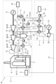
- FIG. 1 is a system configuration diagram of a combined power generation system according to an embodiment of the present invention.
- FIG. 11 is a system configuration diagram of a combined power generation system according to a modified example.
- 1 is a graph showing changes in specific enthalpy when the pressure of various gases is changed. This figure shows the assumptions regarding the thermodynamic properties of the heat source steam (exhaust steam) and the ammonia gas after vaporization used to estimate the exergy change.
- 1 is a graph showing the relationship between the exergy or power required to vaporize ammonia and the pressure of the vaporized ammonia.
- FIG. 1 is a diagram showing an outline of a simplified model of a thermal power generation facility common to Comparative Examples 1 and 2 and Examples 1 to 3.
- FIG. 1 is a diagram showing an overview of a simulation model of Comparative Example 1.
- FIG. 13 is a diagram showing an outline of a simulation model of Comparative Example 2.
- FIG. 1 is a diagram showing an overview of a simulation model of a first embodiment.
- FIG. 13 is a diagram showing an outline of a simulation model of a second embodiment.
- FIG. 13 is a diagram showing an outline of a simulation model of a third embodiment.
- 1 is a graph showing the amount of steam required to produce 1 ton of ammonia gas in each simulation model of Comparative Examples 1 and 2 and Examples 1 to 3.
- 1 is a graph showing the specific exergy of each fluid.
- 1 is a graph showing the estimated results of the total power generation amount in each simulation model of Comparative Examples 1 and 2 and Examples 1 to 3.
- 1 is a graph showing the estimated results of exergy balance per ton of ammonia gas in each simulation model of Comparative Examples 1 and 2 and Examples 1 to 3.
- FIG. 1 is a system configuration diagram of a combined power generation system according to this embodiment. As shown in FIG.
- the combined power generation system 1A includes a first power generation facility 2 that generates a first electric power by utilizing water vapor (hereinafter, simply referred to as "steam"), and a second power generation facility 3 that vaporizes liquid ammonia by utilizing residual heat of the steam generated in the first power generation facility 2 to generate the first electric power, and generates a second electric power by utilizing the vaporized ammonia gas, and is further characterized in that exhaust ammonia gas discharged from the second power generation facility 3 is combusted in a boiler facility 4 of the first power generation facility 2.
- steam water vapor
- the first power generation facility 2 in the combined power generation system 1A can be, for example, a conventional thermal power generation facility that can be directly converted. More specifically, the first power generation facility 2 in the combined power generation system 1A of this embodiment includes a boiler equipment 4 that generates steam, a steam turbine 8 (e.g., a high-pressure steam turbine 8a, an intermediate-pressure steam turbine 8b, and a low-pressure steam turbine 8c) driven by steam generated in the boiler equipment 4, and a first generator 9 connected to the steam turbine 8 to generate electricity.
- a steam turbine 8 e.g., a high-pressure steam turbine 8a, an intermediate-pressure steam turbine 8b, and a low-pressure steam turbine 8c
- the above-mentioned first power generation facility 2 further includes a steam supply pipe Lw (hereinafter simply referred to as "piping Lw ”) for supplying steam (heat medium) generated in the boiler equipment 4, pumps P1 to P3 as a power source for circulating the steam (heat medium) in this pipe Lw , heat exchangers 12 and 13 including a condenser 11, and related equipment or devices such as a deaerator 14 and water supply equipment 10, at desired locations on the pipe Lw .
- the deaerator 14 is a device for removing gases such as oxygen and carbon dioxide present in the heat medium (water) used to operate the steam turbine 8 .
- the second power generation facility 3 in the combined power generation system 1A includes a storage facility 15 for storing liquid ammonia, an ammonia vaporization facility 16 (energy addition facility) for vaporizing the liquid ammonia supplied from this storage facility 15 by utilizing residual heat of exhaust steam discharged from the steam turbine 8 in the first power generation facility 2, an ammonia turbine 20 driven by ammonia gas (superheated ammonia gas) which is the turbine driving fluid produced in this ammonia vaporization facility 16, and a second generator 21 connected to this ammonia turbine 20 for generating second electricity.
- ammonia liquid ammonia and ammonia gas
- La consisting of an independent pipe separate from the above-mentioned pipe Lw .
- the boiler facility 4 of the first power generation facility 2 includes a combustion unit 5. Furthermore, this combustion unit 5 is supplied with fuel (e.g., fossil fuels such as natural gas, coal, and oil, and combustible waste, etc.) from a fuel supply device 6, and is also supplied with exhaust ammonia gas discharged from the ammonia turbine 20 in the second power generation facility 3 as fuel.
- fuel e.g., fossil fuels such as natural gas, coal, and oil, and combustible waste, etc.
- fuel supply device 6 e.g., fossil fuels such as natural gas, coal, and oil, and combustible waste, etc.
- exhaust ammonia gas discharged from the ammonia turbine 20 in the second power generation facility 3 as fuel.
- the fuel supplied from the fuel supply device 6 and the exhaust ammonia gas discharged from the ammonia turbine 20 are mixed and burned, but the fuel supplied to the combustion section 5 may be only the exhaust ammonia gas.
- the power generation method (steam turbine method) of the first power generation facility 2 in the combined power generation system 1A does not have to be limited to the method combining the extraction condensation type and the reheat type shown in FIG. 1, but may be a method adopting any one of these types or any of the methods described below.
- (1) Back pressure type (2) Condensate type (3) Extraction back pressure type
- the exhaust ammonia gas discharged from the ammonia turbine 20 as fuel in the boiler equipment 4 of the first power generation facility 2, it is possible to reduce the amount of carbon dioxide emissions compared to the case where only fuel that emits carbon dioxide is burned in the boiler equipment 4.
- a part of the steam used to operate the steam turbine 8 is diverted as a heat medium for vaporizing the liquid ammonia. Therefore, in the combined power generation system 1A according to this embodiment, the thermal energy supplied to the steam turbine 8 is reduced, which reduces the amount of generated first electric power.
- the ammonia gas vaporized in the ammonia vaporization facility 16 of the second power generation facility 3 is further superheated, and the ammonia turbine 20 is operated using this superheated ammonia gas (turbine driving fluid) to generate second electricity.
- the combined power generation system 1A (or combined power generation method) of this embodiment part or all of the reduction in output of the first power at the first power generation facility 2 can be compensated for by the second power generation at the second power generation facility 3.
- the combined power generation system 1B according to the modified example shown in FIG. 2 the case where the optional facility 22 is one has been described as an example, but the exhaust ammonia gas discharged from the ammonia turbine 20 may be supplied as fuel to two or more optional facilities 22 depending on the scale of the first power generation facility 2 or the like (optional component).
- the combined power generation system 1B according to a modified example may supply exhaust ammonia gas discharged from the ammonia turbine 20 not only to at least one optional equipment 22 but also to the combustion section 5 in the boiler equipment 4 of the first power generation facility 2 (optional component).
- the combined power generation system 1B is specified as a method invention, it is a combined power generation method in which a steam turbine 8 connected to a first generator 9 is driven by steam generated in a boiler facility 4 to generate first electricity, ammonia gas, which is a turbine driving fluid, is generated from liquid ammonia using residual heat of exhaust steam from the steam turbine 8, an ammonia turbine 20 connected to a second generator 21 is driven by ammonia gas to generate second electricity, and exhaust ammonia gas discharged from the ammonia turbine 20 is combusted in the boiler facility 4 or at least one optional facility other than the boiler facility 4 (for example, optional facility 22).
- the combined power generation system 1B according to the above-mentioned modified example (or the combined power generation method according to the modified example) has the same effects as those of the combined power generation system 1A (or the combined power generation method) described in [1-2] above.
- the amount of carbon dioxide emitted from the boiler equipment 4 and/or the at least one optional piece of equipment 22 can be reduced compared to the case where only fuel that emits carbon dioxide is burned in the combustion section 5 of the boiler equipment 4 and/or the combustion section 23 of at least one optional piece of equipment 22.
- the exhaust ammonia gas may be supplied to the combustion section 5 of the boiler equipment 4 shown in FIG. 1 and FIG. 2 or the combustion section 23 of the optional equipment 22 shown in FIG. 2 by using the residual pressure of the exhaust ammonia gas discharged from the ammonia turbine 20 (optional component).
- a gas supply device such as a blower to supply the exhaust ammonia gas discharged from the ammonia turbine 20 to the combustion section 5 and the combustion section 23 .
- the liquid ammonia which is supplied from the storage facility 15 shown in Figures 1 and 2 and is the heat medium that runs the ammonia turbine 20, may contain up to 1 mass % water (optional component).
- the equipment constituting the ammonia feed line La and the ammonia vaporization facility 16 in the first power generation facility 2 is made of steel, it is possible to suppress the occurrence of stress corrosion cracking of the steel. As a result, it is possible to reduce the cost required for maintenance and repair of the second power generation facility 3. This makes it possible to reduce the cost required for generating the second electric power in the second power generation facility 3.
- ⁇ 3-2-2 Temperature of exhaust ammonia gas in the combustion section>
- liquid ammonia which is a heat medium for operating the ammonia turbine 20
- the temperature of the ammonia gas (exhaust ammonia gas) supplied to the combustion section 5 of the boiler equipment 4 shown in FIGS. 1 and 2 or the combustion section 23 of the optional equipment 22 shown in FIG. 2 may be set to 18.8° C. or higher (optional component).
- water in the ammonia gas (exhaust ammonia gas) from condensing under atmospheric pressure, thereby making it possible to suppress corrosion of the steel material constituting the ammonia feed line La (see FIG. 1 or FIG.
- the second power generation facility 3 may include a pressurizing facility P 4 (e.g., a pump) that pressurizes the liquid ammonia to be supplied to the ammonia vaporization facility 16 to 6 MPaG or more (optional component).
- a pressurizing facility P 4 e.g., a pump
- the thermal energy required to generate superheated ammonia gas can be reduced compared to the case of vaporizing and superheating unpressurized liquid ammonia.
- the amount of exhaust steam extracted from the steam turbine 8 of the first power generation facility 2 to vaporize and superheat ammonia in the second power generation facility 3 can be reduced. The reason for this is explained below.
- Figure 3 is a graph showing the change in specific enthalpy when the pressure of various gases is changed.
- the specific enthalpy of various gases shown in Figure 3 was estimated using "REFPROP Version 10" of the National Institute of Standards and Technology (NSIT).
- NIT National Institute of Standards and Technology
- the specific enthalpy of ammonia ( NH3 ), water ( H2O ), methanol, and ethanol tended to depend on pressure.
- the specific enthalpy of polar molecules such as ammonia has pressure dependence.
- the combined power generation system 1A according to this embodiment or the combined power generation system 1B according to the modified example by pressurizing liquid ammonia to a pressure close to the critical pressure when vaporizing it, it is possible to reduce the thermal energy required for vaporization, i.e., the amount of exhaust steam extracted from the first power generation facility 2, compared to the case of vaporizing unpressurized ammonia.
- liquid ammonia undergoes a smaller volume change when pressurized than ammonia gas, so the amount of power energy required to pressurize liquid ammonia is less than that required to pressurize ammonia gas.
- the total energy of the steam supplied to the inlet of a steam turbine (e.g., the steam turbine 8) in a thermal power generation facility is a combination of the above-mentioned (i) electrical energy and (ii) thermal energy, and is generally referred to as "enthalpy (H)."
- the enthalpy (H) is defined by the following (Equation 1).
- H enthalpy
- S entropy
- the exergy obtained from the thermal power generation facility (e.g., first power generation facility 2) or the like is the maximum work (electrical energy) that can be extracted from the energy of steam supplied to the inlet of the steam turbine (e.g., steam turbine 8) before this steam reaches an arbitrary reference environmental state.
- FIG. 4A is a diagram showing preconditions for the thermodynamic properties of steam (exhaust steam) as a heat source used in estimating the exergy change shown in FIG. 4B and ammonia gas after vaporization.
- FIG. 4B is a graph showing the relationship between the exergy or power required for vaporizing liquid ammonia and the pressure of the vaporized ammonia.
- the thermodynamic properties of the steam (exhaust steam) and ammonia shown in Fig. 4A were also estimated using "REFPROP Version 10" by the National Institute of Standards and Technology (NSIT). In the graph of FIG.
- “Curve 3" is the difference obtained by subtracting the value of "Line 1" and the value of “Curve 1” from the value of "Curve 2" at an arbitrary pressure value of vaporized ammonia (the value on the X-axis).
- this exergy balance (Curve 3) is, the more the total power generation amount of the first power generation facility 2 and the second power generation facility 3 increases compared to the power generation amount of a conventional thermal power generation facility (corresponding to only the first power generation facility 2).
- the exergy balance begins to increase less when the vaporized ammonia pressure (X-axis) exceeds 6 MPaG, and peaks at 16 MPaG.
- the volume of liquid ammonia changes less when pressurized than that of vaporized ammonia gas. Therefore, even if additional power energy (line 1) is required to drive the pressurizing equipment P4 in the second power generation facility 3 shown in FIG. 1 or 2, the increase in power energy has a small effect on the exergy balance (curve 3) described above (see FIG. 4B).
- ammonia which is a polar molecule
- the liquid ammonia supplied to the ammonia vaporization equipment 16 is pressurized to 6 MPaG or more, so that the total power generation amount of the first power generation facility 2 and the second power generation facility 3 can be made larger than the power generation amount of a conventional thermal power generation facility (corresponding to only the first power generation facility 2).
- the upper limit of the liquid ammonia pressure is desirably set to less than 11.2 MPaG, which is the critical pressure of ammonia.
- the steam turbine 8 in the first power generation facility 2 may include, for example, a high-pressure steam turbine 8a that discharges high-pressure exhaust steam, an intermediate-pressure steam turbine 8b that discharges intermediate-pressure exhaust steam having an outlet temperature of 200 to 450°C, and a low-pressure steam turbine 8c that discharges low-pressure exhaust steam having an outlet temperature of 30 to 200°C. Furthermore, as shown in FIGS.
- the ammonia vaporization equipment 16 in the second power generation facility 3 may include a preheater 17 (heat exchanger) that preheats the liquid ammonia supplied from the storage equipment 15, a vaporizer 18 (heat exchanger) that vaporizes the liquid ammonia preheated in the preheater 17, and a superheater 19 (heat exchanger) that superheats the ammonia gas vaporized in the vaporizer 18.
- a preheater 17 heat exchanger
- vaporizer 18 heat exchanger
- superheater 19 heat exchanger
- first power generation facility 2 and the second power generation facility 3 shown in Figure 1 or Figure 2 are configured as described above, they may be provided with a medium-pressure exhaust steam supply line L1 (the part indicated by a dashed line in piping Lw in Figures 1 and 2) that supplies a portion of the medium-pressure exhaust steam discharged from the medium-pressure steam turbine 8b of the first power generation facility 2 to the superheater 19 and supplies a portion of the medium-pressure exhaust steam cooled in the superheater 19 to the vaporizer 18 (optional component).
- L1 the medium-pressure exhaust steam supply line L1 (the part indicated by a dashed line in piping Lw in Figures 1 and 2) that supplies a portion of the medium-pressure exhaust steam discharged from the medium-pressure steam turbine 8b of the first power generation facility 2 to the superheater 19 and supplies a portion of the medium-pressure exhaust steam cooled in the superheater 19 to the vaporizer 18 (optional component).
- the liquid ammonia can be efficiently vaporized by utilizing the exhaust steam (medium pressure exhaust steam) supplied from the first power generation facility 2. More specifically, when comparing the latent heat of vaporization of superheated ammonia (ammonia gas) and that of low-pressure exhaust steam, the latent heat of vaporization of the low-pressure exhaust steam is significantly larger.
- Latent heat of vaporization of water vapor at 144 ° C: 2130 (kJ / kg) Therefore, by using the medium-pressure exhaust steam discharged from the medium-pressure steam turbine 8b of the first power generation facility 2 as the heat source used in the superheater 19 and vaporizer 18 of the ammonia vaporization equipment 16, ammonia can be efficiently vaporized and superheated using a small amount of medium-pressure exhaust steam. As a result, the output of the ammonia turbine 20 by the superheated ammonia gas can be increased.
- a hot water supply line L 2 (a portion indicated by a dashed dotted line in the piping L w in FIG. 1 and FIG. 2 ) may be provided to supply hot water (second hot water) generated from equipment related to the low-pressure steam turbine 8 c of the first power generation facility 2 to the preheater 17 of the ammonia vaporization facility 16 in the second power generation facility 3 (optional component).
- the second hot water in the hot water supply line L2 may be hot water after heat exchange generated in a condenser 11 (heat exchanger) and/or a heat exchanger 12 provided downstream of the low-pressure steam turbine 8c of the first power generation facility 2 shown in Fig. 1 or 2. More specifically, the second hot water may be, for example, feed water on the low-pressure steam turbine 8c side of the first power generation facility 2, a feed water heater drain, or the like.
- a line may be provided to supply hot water (first hot water) generated from the vaporizer 18 of the ammonia vaporization equipment 16 in the second power generation facility 3 or its related equipment to the preheater 17, and this line may be used as the hot water supply line L2 (not shown).
- the first hot water may be, for example, evaporator drain.
- the combined power generation system 1A according to this embodiment or the combined power generation system 1B according to the modified example includes a hot water supply line L2 in addition to the intermediate pressure exhaust steam supply line L1 , the exhaust heat discharged into the environment in the first power generation facility 2 can be effectively utilized for vaporizing (more specifically, preheating) the liquid ammonia.
- the first power generation facility 2 has one each of a high-pressure steam turbine 8a, an intermediate-pressure steam turbine 8b, and a low-pressure steam turbine 8c, but the first power generation facility 2 may have multiple each of the high-pressure steam turbine 8a, the intermediate-pressure steam turbine 8b, and the low-pressure steam turbine 8c (optional components).
- the first power generation facility 2 may include a plurality of ammonia turbines 20 as necessary (optional components). In either case, the same actions and effects as those of the combined power generation system 1A according to this embodiment or the combined power generation system 1B according to the modified example are achieved.
- the turbine driving fluid that drives the ammonia turbine 20 is ammonia gas (superheated ammonia gas) as an example.
- this turbine driving fluid may be a supercritical ammonia fluid (optional component).
- an energy addition equipment (not shown) is provided that heats (residual heat of exhaust steam) and pressurizes (power for a pump or the like) liquid ammonia to generate a supercritical fluid of ammonia.
- the supercritical ammonia fluid produced in the energy addition facility is vaporized in an ammonia turbine 20 .
- the pressure of the ammonia is desirably set to 11.2 to 16 MPaG, which is the critical pressure of ammonia, taking into account the exergy balance (see FIG. 4B).
- FIGS. ⁇ 4-1: Simulation settings, etc.> A simplified type thermal power generation facility corresponding to the first power generation facility 2 shown in FIG. 1 was used as a model (see FIG. 5 below, hereinafter also simply referred to as the "simplified model"), and the method of vaporizing liquid ammonia supplied to the combustion section 5 of the boiler facility 4 was set to the following five types (Comparative Examples 1 and 2 and Examples 1 to 3), and the exergy balance was simulated.
- FIG. 5 is a diagram showing an outline of a simplified model of a thermal power generation facility (corresponding to the first power generation facility 2 in FIG. 1 ) common to the following five cases (Comparative Examples 1 and 2 and Examples 1 to 3).
- FIG. 5 is a diagram showing an outline of a simplified model of a thermal power generation facility (corresponding to the first power generation facility 2 in FIG. 1 ) common to the following five cases (Comparative Examples 1 and 2 and Examples 1 to 3).
- FIG. 6 is a diagram showing an outline of the simulation model of Comparative Example 1.
- FIG. 7 is a diagram showing an outline of the simulation model of Comparative Example 2.
- FIG. 8 is a diagram showing an outline of the simulation model of Example 1.
- FIG. 9 is a diagram showing an outline of the simulation model of Example 2.
- FIG. 10 is a diagram showing an outline of the simulation model of Example 3. In each of the simulation models shown in Figs. 8 to 10, the destination of the exhaust ammonia gas discharged from the ammonia gas turbine (corresponding to the ammonia turbine 20 in Figs. 1 and 2) is simply displayed as "to the boiler".
- FIG. 11 is a graph showing the amount of steam required to produce 1 ton of ammonia gas in each of the simulation models of Comparative Examples 1 and 2 and Examples 1 to 3.
- the steam (thermal energy) used to operate the steam turbine is used to vaporize the liquid ammonia.
- a reduction in the output of the steam turbine is unavoidable.
- Fig. 12 is a graph showing the specific exergy of each fluid.
- Fig. 13 is a graph showing the estimated results of the total power generation amount in each simulation model of Comparative Examples 1 and 2 and Examples 1 to 3.
- the estimated values of the specific exergy of each fluid shown in Fig. 12 were used to estimate the total power generation amount for each simulation model shown in Fig. 13.
- the reference environment settings used to calculate the specific exergy of each fluid shown in Fig. 12 are shown in Table 2 below.
- the specific exergy of each fluid was estimated using "REFPROP Version 10" from the National Institute of Standards and Technology (NSIT) in the United States.
- superheated ammonia gas (pressurized superheated vaporized NH 3 ) has a specific exergy approximately equal to that of steam (300 kPaG steam) for operating an intermediate pressure (steam) turbine. Therefore, as shown in Figure 13, by operating an ammonia gas turbine ( NH3 turbine) with superheated ammonia gas (pressurized superheated vaporized NH3 ) generated using the residual heat of the steam (300 kPaG steam) for operating the medium-pressure (steam) turbine, it is possible to compensate for the output loss of the medium-pressure (steam) turbine in a simplified model of a thermal power plant.
- FIG. 14 is a graph showing the estimation results of the exergy balance per ton of ammonia gas in each of the simulation models of Comparative Examples 1 and 2 and Examples 1 to 3. As shown in FIG. 14, in Examples 1 to 3 in which the vaporized ammonia gas was further converted into superheated ammonia gas to operate the ammonia gas turbine, the exergy balance was positive.
- the combined power generation system 1A of this embodiment or the combined power generation system 1B of the modified example as well as the combined power generation system of the present invention in which the turbine driving fluid in the second power generation facility 3 is ammonia supercritical fluid, a large amount of ammonia gas for fuel can be produced while suppressing energy loss during vaporization.
- the present invention is a combined power generation system and method that can heat liquid ammonia to produce a large amount of ammonia gas for combustion, and that can suppress a decrease in the power output of a power generation facility even if thermal energy for power generation in the power generation facility is diverted, and can be used in technical fields related to combined facilities such as power generation facilities and chemical plants.
Landscapes
- Engineering & Computer Science (AREA)
- Chemical & Material Sciences (AREA)
- Combustion & Propulsion (AREA)
- Mechanical Engineering (AREA)
- General Engineering & Computer Science (AREA)
- Engine Equipment That Uses Special Cycles (AREA)
- Feeding And Controlling Fuel (AREA)
Abstract
Description
本発明は、液体アンモニアを気化して燃焼用のアンモニアガスを生成する際のエネルギー損失を少なくする又は無くすことができる複合発電システム及びその方法に関する。 The present invention relates to a combined power generation system and method that can reduce or eliminate energy loss when vaporizing liquid ammonia to produce ammonia gas for combustion.
一般に、アンモニア(NH3)は、常温(20℃、0.875MPaG(蒸気圧))では気体であるが冷却や加圧で容易に液化でき、燃料として使用する場合は液体のまま輸送や貯留することができる。このため、容易に液化できない気体燃料を取り扱う場合に比べて輸送や貯留に要するコストを低減できる。また、近年アンモニアは、燃焼時に温室効果ガスである二酸化炭素(CO2)を排出しない燃料として注目されている。
このため、石炭等の化石燃料を使用する従来の火力発電施設において、燃料の一部としてアンモニアを用いることで温室効果ガスである二酸化炭素の排出量を低減する試みもなされている。
その一方で、アンモニアを燃料として用いる場合は、液体アンモニアを気化してアンモニアガスにする必要がある。
Generally, ammonia (NH 3 ) is a gas at room temperature (20° C., 0.875 MPaG (vapor pressure)), but can be easily liquefied by cooling or pressurization, and when used as a fuel, it can be transported and stored in liquid form. This allows for reduced costs for transportation and storage compared to handling gaseous fuels that cannot be easily liquefied. Furthermore, in recent years, ammonia has been attracting attention as a fuel that does not emit carbon dioxide (CO 2 ), a greenhouse gas, when burned.
For this reason, in conventional thermal power plants that use fossil fuels such as coal, attempts have been made to reduce emissions of carbon dioxide, a greenhouse gas, by using ammonia as part of the fuel.
On the other hand, when ammonia is used as fuel, liquid ammonia needs to be vaporized to form ammonia gas.
アンモニアの沸点は-33.34℃であり、水に比べて大幅に低い。このため、液体アンモニアを気化させる際は、工業用水や海水を熱媒体として用いて容易に液体アンモニアを気化させることができる。
その一方で、液体アンモニアを気化させる際の熱媒体として工業用水や海水を使用する場合は、これらの揚水に要するエネルギーコストが増大することが予想される。このため、エネルギー収支の観点から、アンモニアを燃料として使用する際のコスト的なメリットが薄くなるという懸念があった。
このような事情に鑑み、従来の火力発電施設等において生じる余熱を利用して液体アンモニアを気化させて燃料として利用することが行われている。
当該技術分野の先願としては、例えば特許文献1に開示される「発電プラント用のアンモニア供給ユニット、発電プラント用のアンモニア気化処理方法、及び発電プラント」等が知られている。
The boiling point of ammonia is -33.34°C, which is significantly lower than that of water. Therefore, when vaporizing liquid ammonia, it can be easily vaporized by using industrial water or seawater as a heat medium.
On the other hand, if industrial water or seawater is used as a heat medium for vaporizing liquid ammonia, the energy costs required for pumping the water are expected to increase, and there was concern that the cost benefits of using ammonia as fuel would be diminished from the perspective of energy balance.
In view of these circumstances, liquid ammonia has been vaporized using residual heat generated in conventional thermal power plants and the like and used as fuel.
As a prior application in this technical field, for example, "Ammonia supply unit for power plant, ammonia vaporization treatment method for power plant, and power plant" disclosed in
上述の特許文献1に開示される発明によれば、従来の火力発電施設等において生じる排熱を用いることで、気化時のエネルギー損失を極力抑制しながら燃焼用のアンモニアガスを生成できるものの、火力発電施設等において利用可能な排熱量は限られている。
このため、特許文献1を参酌する場合は、気化できる液体アンモニアの量に限りがあった。
According to the invention disclosed in the above-mentioned
For this reason, when
本発明はかかる従来の事情に対処してなされたものでありその目的は、多量の液体アンモニアを気化せしめて燃焼用のアンモニアガスを生成することができ、かつ、気化によるエネルギー損失を少なくする又は無くすことができる複合発電システム及びその方法を提供することにある。 The present invention was made to address these conventional problems, and its purpose is to provide a combined power generation system and method capable of vaporizing a large amount of liquid ammonia to generate ammonia gas for combustion, while reducing or eliminating the energy loss caused by vaporization.
上記課題を解決するための第1の発明である複合発電システムは、蒸気を生成するボイラー設備と、その蒸気によって駆動される蒸気タービンと、この蒸気タービンに接続されて発電する第1の発電機を有する第1の発電施設と、液体アンモニアを貯蔵する貯蔵設備と、この貯蔵設備から供給される液体アンモニアを蒸気タービンの排蒸気の余熱を用いてタービン駆動流体にするエネルギー付加設備と、このエネルギー付加設備において生成したタービン駆動流体によって駆動されるアンモニアタービンと、このアンモニアタービンに接続されて発電する第2の発電機を有する第2の発電施設を備え、ボイラー設備、又は、アンモニアタービンから排出される排アンモニアガスを燃焼可能な燃焼部を有しかつボイラー設備以外の少なくとも1の任意の設備、において排アンモニアガスを燃焼させることを特徴とする。
上記構成の第1の発明において、第1の発電施設は、ボイラー設備で生成した蒸気により蒸気タービンを駆動して、この蒸気タービンに接続される第1の発電機により第1の電力を発電するという作用を有する。
また、第2の発電施設のエネルギー付加設備は、貯蔵設備から供給される液体アンモニアを、第1の発電施設における蒸気タービンの排蒸気の余熱を利用してタービン駆動流体(過熱アンモニアガス又はアンモニアの超臨界流体)を生成するという作用を有する。さらに、第2の発電施設では、エネルギー付加設備において生成されるタービン駆動流体により、アンモニアタービンを駆動して、このアンモニアタービンに接続される第2の発電機により第2の電力を発電するという作用を有する。
さらに、第2の発電施設のアンモニアタービンから排出される排アンモニアガスは、ボイラー設備、又はこのボイラー設備以外の少なくとも1の任意の設備、において燃焼用のアンモニアガスとして用いられる。
つまり、第1の発明では、第1の発電施設において蒸気により第1の電力を発電しつつ、この蒸気の一部を用いて第2の発電施設において生成されるタービン駆動流体を用いて第2の電力を発電し、さらに第2の発電施設から排出される排アンモニアガスが燃料として使用される。
A combined cycle power generation system as a first invention for solving the above problems comprises a first power generation facility having a boiler facility for generating steam, a steam turbine driven by the steam, and a first generator connected to the steam turbine for generating power, a storage facility for storing liquid ammonia, an energy addition facility for converting the liquid ammonia supplied from the storage facility into a turbine driving fluid by using residual heat of exhaust steam from the steam turbine, an ammonia turbine driven by the turbine driving fluid generated in the energy addition facility, and a second power generation facility having a second generator connected to the ammonia turbine for generating power, and is characterized in that the exhaust ammonia gas is combusted in the boiler facility, or in at least one arbitrary facility other than the boiler facility, which has a combustion section capable of combusting exhaust ammonia gas discharged from the ammonia turbine.
In the first invention having the above configuration, the first power generation facility has the effect of driving a steam turbine with steam generated in the boiler equipment, and generating first electricity with a first generator connected to this steam turbine.
The energy addition equipment of the second power generation facility has an effect of generating a turbine driving fluid (superheated ammonia gas or ammonia supercritical fluid) from liquid ammonia supplied from the storage facility by utilizing residual heat of exhaust steam from the steam turbine of the first power generation facility. Furthermore, the second power generation facility has an effect of driving an ammonia turbine with the turbine driving fluid generated in the energy addition equipment, and generating second electricity with a second generator connected to the ammonia turbine.
Furthermore, the waste ammonia gas discharged from the ammonia turbine of the second power generation facility is used as ammonia gas for combustion in the boiler facility or in at least one optional facility other than the boiler facility.
In other words, in the first invention, a first electric power is generated using steam in a first power generation facility, while a turbine driving fluid is produced in a second power generation facility using a portion of this steam to generate a second electric power, and further, exhaust ammonia gas discharged from the second power generation facility is used as fuel.
第2の発明は、上述の第1の発明であって、排アンモニアガスは、ボイラー設備において燃焼されることを特徴とする。
上記構成の第2の発明は、アンモニアタービンから排出される排アンモニアガスを燃焼させる設備がボイラー設備に特定されている。よって、第2の発明による作用は、第1の発明による作用と同じである。
また、第2の発明では、アンモニアタービンから排出される排アンモニアガスをボイラー設備の燃料として用いることで、第1の発電施設において第1の電力を発電する際の二酸化炭素の排出量を削減するという作用を有する。
A second invention is the above-mentioned first invention, characterized in that the exhaust ammonia gas is combusted in a boiler facility.
In the second invention having the above configuration, the equipment for combusting the exhaust ammonia gas discharged from the ammonia turbine is specified to be a boiler equipment. Therefore, the operation of the second invention is the same as that of the first invention.
In addition, in the second invention, by using the exhaust ammonia gas discharged from the ammonia turbine as fuel for the boiler equipment, it has the effect of reducing the amount of carbon dioxide emissions when generating the first electric power in the first power generation facility.
第3の発明は、上述の第1又は第2の発明であって、エネルギー付加設備に供給する液体アンモニアを6MPaG以上に加圧する加圧設備を備えることを特徴とする。
上記構成の第3の発明は、上述の第1又は第2の発明による作用と同じ作用を有する。さらに、第3の発明では、エネルギー付加設備に供給する液体アンモニアを6MPaG以上に加圧しておくことで、無加圧の液体アンモニアを用いる場合に比べて、第1及び第2の発電施設における総発電量を増加させるという作用を有する。
A third invention is the above-mentioned first or second invention, characterized in that it further comprises a pressurizing facility for pressurizing the liquid ammonia to be supplied to the energy addition facility to 6 MPaG or more.
The third invention having the above configuration has the same effect as the first or second invention. Furthermore, the third invention has the effect of increasing the total amount of power generation in the first and second power generation facilities by pressurizing the liquid ammonia to be supplied to the energy-adding equipment to 6 MPaG or more, compared to the case where unpressurized liquid ammonia is used.
第4の発明は、上述の第1又は第2の発明であって、蒸気タービンは、出口温度が200~450℃である中圧排蒸気を排出する中圧蒸気タービンと、出口温度が30~200℃である低圧排蒸気を排出する低圧蒸気タービンを備え、エネルギー付加設備はアンモニア気化設備であり、液体アンモニアを予熱する予熱器と、この予熱器において予熱された液体アンモニアを気化させる気化器と、この気化器において気化されたアンモニアガスを過熱する過熱器を備え、中圧排蒸気の一部を過熱器に供給するとともに、過熱器において減温された中圧排蒸気の一部を気化器に供給する中圧排蒸気供給ラインと、気化器又はその関連機器から生じる第1の温水、及び/又は、低圧蒸気タービンの関連機器から生じる第2の温水、を予熱器に供給する温水供給ラインを備えることを特徴とする。
上記構成の第4の発明は、上述の第1又は第2の発明による作用と同じ作用を有する。また、第4の発明では、アンモニア気化設備の過熱器において、中圧排蒸気を利用して気化器において気化されたアンモニアガスを過熱するとともに、過熱器において使用済の中圧排蒸気の一部を気化器に供給して(=中圧排蒸気供給ライン)液体アンモニアの気化に利用することで、過熱アンモニアガスを効率良く生成させるという作用を有する。
また、第4の発明では、気化器又はその関連機器から生じる第1の温水、及び/又は、低圧蒸気タービンの関連機器から生じる第2の温水、を利用して(=温水供給ライン)予熱器に送給された液体アンモニアを予熱することで、気化器又はその関連機器が有する余熱、及び/又は、低圧蒸気タービンから生じる排熱を有効利用して、効率良く液体アンモニアを予熱するという作用を有する。
特に、第4の発明が温水供給ラインを備えることで、環境に放出される排熱量を減らすことができる。
A fourth invention is the first or second invention described above, wherein the steam turbine comprises a medium-pressure steam turbine that discharges medium-pressure exhaust steam having an outlet temperature of 200 to 450 ° C., and a low-pressure steam turbine that discharges low-pressure exhaust steam having an outlet temperature of 30 to 200 ° C., and the energy-adding equipment is an ammonia vaporization equipment, and comprises a preheater that preheats liquid ammonia, a vaporizer that vaporizes the liquid ammonia preheated in the preheater, and a superheater that superheats the ammonia gas vaporized in the vaporizer, and is characterized in that it comprises a medium-pressure exhaust steam supply line that supplies a portion of the medium-pressure exhaust steam to the superheater and a portion of the medium-pressure exhaust steam that has been reduced in temperature in the superheater to the vaporizer, and a hot water supply line that supplies the first hot water generated from the vaporizer or its related equipment and/or the second hot water generated from the related equipment of the low-pressure steam turbine to the preheater.
The fourth invention having the above configuration has the same effect as the first or second invention. In addition, in the fourth invention, the superheater of the ammonia vaporization equipment uses medium-pressure exhaust steam to superheat the ammonia gas vaporized in the vaporizer, and supplies a portion of the medium-pressure exhaust steam used in the superheater to the vaporizer (=medium-pressure exhaust steam supply line) to use it for vaporizing liquid ammonia, thereby efficiently generating superheated ammonia gas.
In addition, in the fourth invention, the first hot water generated from the vaporizer or its associated equipment and/or the second hot water generated from the associated equipment of the low-pressure steam turbine is used (=hot water supply line) to preheat the liquid ammonia fed to the preheater, thereby effectively utilizing the residual heat of the vaporizer or its associated equipment and/or the exhaust heat generated from the low-pressure steam turbine to efficiently preheat the liquid ammonia.
In particular, since the fourth invention is provided with a hot water supply line, the amount of waste heat released into the environment can be reduced.
第5の発明は、上述の第1の発明であって、アンモニアタービンから排出される排アンモニアガスの余圧により、ボイラー設備又は任意の設備に排アンモニアガスを供給することを特徴とする。
上記構成の第5の発明は、上述の第1の発明による作用と同じ作用を有する。また、第5の発明では、ボイラー設備又は任意の設備に排アンモニアガスを供給するための供給設備が不要になる。
A fifth invention is the above-mentioned first invention, characterized in that the exhaust ammonia gas is supplied to a boiler facility or any facility by using the residual pressure of the exhaust ammonia gas discharged from the ammonia turbine.
The fifth aspect of the invention has the same effect as that of the first aspect of the invention. In addition, the fifth aspect of the invention does not require a supply facility for supplying exhaust ammonia gas to a boiler facility or any other facility.
第6の発明は、上述の第1の発明であって、液体アンモニアは1質量%以下の水を含有することを特徴とする。
上記構成の第6の発明は、上述の第1の発明による作用と同じ作用を有する。また、第6の発明では、第2の発電施設における液体アンモニアやアンモニアガスの送給配管の材質として特に鋼材を用いる場合に、鋼材が応力腐食割れを起こすのを抑制するという作用を有する。
A sixth invention is the above-mentioned first invention, characterized in that the liquid ammonia contains 1 mass % or less of water.
The sixth invention having the above configuration has the same effect as the first invention. In addition, the sixth invention has an effect of suppressing stress corrosion cracking of steel, particularly when steel is used as the material for the supply pipes for liquid ammonia or ammonia gas in the second power generation facility.
第7の発明は、上述の第6の発明であって、ボイラー設備又は任意の設備、の燃焼部に供給される排アンモニアガスの温度は18.8℃以上であることを特徴とする。
上記構成の第7の発明は、上述の第6の発明による作用と同じ作用を有する。また、第7の発明では、ボイラー設備又は任意の設備、の燃焼部に供給される排アンモニアガスの温度が18.8℃以上に設定されることで、特に大気圧下において、排アンモニアガスが通過する燃焼部の表面に結露が生じるのを防ぐという作用を有する。
この場合、燃焼部において排アンモニアガスが接触する鋼材の表面に結露が生じて、その結露水により鋼材が腐食するのを抑制するという作用を有する。
A seventh invention is the sixth invention, characterized in that the temperature of the exhaust ammonia gas supplied to the combustion section of the boiler facility or any facility is 18.8° C. or higher.
The seventh invention having the above-mentioned configuration has the same effect as the sixth invention. In addition, the seventh invention has the effect of preventing condensation from occurring on the surface of the combustion part through which the exhaust ammonia gas passes, particularly under atmospheric pressure, by setting the temperature of the exhaust ammonia gas supplied to the combustion part of the boiler equipment or any equipment to 18.8°C or higher.
In this case, condensation occurs on the surface of the steel material that comes into contact with the exhaust ammonia gas in the combustion section, and this has the effect of suppressing corrosion of the steel material caused by the condensed water.
第8の発明である複合発電方法は、第1の発電機が接続される蒸気タービンをボイラー設備において生成される蒸気により駆動して第1の電力を発電するとともに、蒸気タービンの排蒸気の余熱を用いて液体アンモニアからタービン駆動流体を生成し、第2の発電機が接続されるアンモニアタービンをタービン駆動流体により駆動して第2の電力を発電し、ボイラー設備、又は、ボイラー設備以外の少なくとも1の任意の設備、においてアンモニアタービンから排出される排アンモニアガスを燃焼させることを特徴とする。
上記構成の第8の発明は、上述の第1の発明を方法の発明として特定したものであり、第8の発明による作用は、第1の発明による作用と同じである。
A combined cycle power generation method according to an eighth aspect of the present invention is characterized in that a steam turbine connected to a first generator is driven by steam generated in a boiler facility to generate first electric power, a turbine driving fluid is generated from liquid ammonia using residual heat of exhaust steam from the steam turbine, an ammonia turbine connected to a second generator is driven by the turbine driving fluid to generate second electric power, and exhaust ammonia gas discharged from the ammonia turbine is combusted in the boiler facility or at least one arbitrary facility other than the boiler facility.
The eighth invention having the above-mentioned configuration specifies the above-mentioned first invention as a method invention, and the action of the eighth invention is the same as the action of the first invention.
上述のような第1の発明によれば、第1の発電施設において発電用に生成される蒸気(熱)の一部を利用して、燃焼用に使用する多量の液体アンモニアの気化を行うことができる。
また、第1の発明によれば、ボイラー設備又は任意の設備において、熱エネルギーを得るための燃料の少なくとも一部としてアンモニアガス(排アンモニアガス)を用いることで、燃焼による熱エネルギーを得る際の二酸化炭素の排出量を削減することができる。
さらに、第1の発明によれば、多量の液体アンモニアを気化させる際の熱源として、第1の発電施設の発電用の蒸気(熱)の一部を転用することによる第1の電力の発電量の低下の一部又は全部を、第2の発電施設における第2の電力の発電により補うことができる。
よって、第1の発明によれば、第1の発電施設と第2の発電施設を併用することで、多量の液体アンモニアを気化させる際のエネルギー損失を少なくする又は無くすことができる。
According to the first invention as described above, a portion of the steam (heat) generated for power generation in the first power generation facility can be utilized to vaporize a large amount of liquid ammonia to be used for combustion.
In addition, according to the first invention, by using ammonia gas (exhaust ammonia gas) as at least a part of the fuel for obtaining thermal energy in a boiler facility or any facility, it is possible to reduce the amount of carbon dioxide emissions when obtaining thermal energy by combustion.
Furthermore, according to the first invention, a part of the steam (heat) used for power generation at the first power generation facility can be diverted as a heat source for vaporizing a large amount of liquid ammonia, and a part or all of the reduction in the amount of power generated from the first power generation facility can be compensated for by the generation of the second power generation facility.
Therefore, according to the first invention, by using the first power generation facility and the second power generation facility in combination, it is possible to reduce or eliminate energy loss when vaporizing a large amount of liquid ammonia.
第2の発明によれば、上述の第1の発明による効果と同じ効果を奏する。さらに、第2の発明によれば、第1の発電施設において第1の電力を発電する際に、燃料として化石燃料のみを用いる場合に比べて、二酸化炭素の排出量を削減できる。 The second invention provides the same effects as the first invention described above. Furthermore, the second invention can reduce carbon dioxide emissions when generating the first electric power in the first power generation facility, compared to when only fossil fuels are used as fuel.
第3の発明によれば、上述の第1又は第2の発明による効果と同じ効果を奏する。加えて、第3の発明によれば、液体アンモニアを特定の圧力以上に加圧することで、タービン駆動流体を生成するために第1の発電施設から抽気する排蒸気量を、無加圧の液体アンモニアを用いてタービン駆動流体を生成する場合に比べて少なくすることができる。
よって、第3の発明によれば、第1の発電施設から転用する熱エネルギーを、第2の発電施設において効率良く電気エネルギーに変換することができる。
According to the third invention, the same effects as those of the first or second invention described above can be achieved. In addition, according to the third invention, by pressurizing liquid ammonia to a specific pressure or higher, the amount of exhaust steam extracted from the first power generation facility to generate the turbine driving fluid can be reduced compared to the case where the turbine driving fluid is generated using unpressurized liquid ammonia.
Therefore, according to the third aspect of the present invention, the thermal energy diverted from the first power generation facility can be efficiently converted into electrical energy in the second power generation facility.
第4の発明によれば、上述の第1又は第2の発明による効果と同じ効果を奏する。加えて、第4の発明によれば、中圧排蒸気の余熱をアンモニアガスの過熱(加熱器)と液体アンモニアの気化(気化器)に、この順序で供給するとともに、気化器において使用済の中圧排蒸気の余熱、及び/又は、低圧蒸気タービンの関連機器から生じる排熱を液体アンモニアの予熱(予熱器)に使用することで、過熱アンモニアガスの生成に用いられる熱エネルギーの損失を極力抑制することができる。
この結果、第4の発明によれば、第1の発電施設から転用した熱エネルギーを、第2の発電施設における第2の電力の発電に有効に活用することができる。
According to the fourth invention, the same effect as that of the first or second invention is obtained. In addition, according to the fourth invention, the residual heat of the medium-pressure exhaust steam is supplied to the superheating of ammonia gas (heater) and the vaporization of liquid ammonia (vaporizer) in this order, and the residual heat of the medium-pressure exhaust steam used in the vaporizer and/or the exhaust heat generated from the related equipment of the low-pressure steam turbine is used to preheat the liquid ammonia (preheater), thereby minimizing the loss of thermal energy used to generate superheated ammonia gas.
As a result, according to the fourth aspect of the present invention, the thermal energy diverted from the first power generation facility can be effectively utilized for generating the second electric power in the second power generation facility.
第5の発明によれば、上述の第1の発明による効果と同じ効果を奏する。加えて、第5の発明によれば、ボイラー設備又は任意の設備に、排アンモニアガスを供給するための供給設備を別途設ける必要がないので、第5の発明の施設構造を簡素にできる。また、第5の発明によれば、排アンモニアガスを供給するための供給設備を有しないので、その稼働やメンテナンス等に要するコストも節減できる。したがって、第5の発明によれば、第1及び第2の電力を発電する際のコストを削減できる。 The fifth invention provides the same effects as the first invention described above. In addition, the fifth invention does not require a separate supply facility for supplying exhaust ammonia gas to the boiler facility or any other facility, so the facility structure of the fifth invention can be simplified. Furthermore, the fifth invention does not require a supply facility for supplying exhaust ammonia gas, so the costs required for its operation and maintenance can be reduced. Therefore, the fifth invention can reduce the costs of generating the first and second electric power.
第6の発明によれば、上述の第1の発明による効果と同じ効果を奏する。加えて、第6の発明によれば、アンモニアが水を含有しない場合に比べて、第2の発電施設におけるアンモニア送給配管が損傷するリスクを低減することができる。
このため、第6の発明によれば、第2の発電施設の修理やメンテナンスに要するコストを削減できる。この結果、第6の発明によれば、特に第2の電力を発電する際のコストを削減できる。
According to the sixth aspect of the present invention, the same effects as those of the first aspect of the present invention can be obtained. In addition, according to the sixth aspect of the present invention, the risk of damage to the ammonia feed pipe in the second power generation facility can be reduced compared to a case where the ammonia does not contain water.
Therefore, according to the sixth aspect of the present invention, it is possible to reduce costs required for repair and maintenance of the second power generation facility. As a result, according to the sixth aspect of the present invention, it is possible to reduce costs, particularly when generating the second electric power.
第7の発明によれば、上述の第6の発明による効果と同じ効果を奏する。加えて、第7の発明によれば、ボイラー設備又は任意の設備、の燃焼部が結露した水により腐食するなどして劣化したり損傷したりするのを抑制できる。
このため、第7の発明によれば、ボイラー設備又は任意の設備、の修理やメンテナンスに要するコストを節減できる。この結果、第7の発明によれば、排アンモニアガスを燃焼させる設備を稼働させる際のコストを削減できる。
According to the seventh aspect of the present invention, the same effects as those of the sixth aspect of the present invention can be obtained. In addition, according to the seventh aspect of the present invention, it is possible to suppress deterioration or damage caused by corrosion or the like of the combustion part of the boiler equipment or any equipment due to condensed water.
Therefore, according to the seventh invention, it is possible to reduce the cost required for repair and maintenance of the boiler equipment or any equipment. As a result, according to the seventh invention, it is possible to reduce the cost of operating the equipment that combusts the exhaust ammonia gas.
第8の発明は、上述の第1の発明を方法の発明として特定したものであり、第8の発明による効果は、第1の発明による効果と同じである。
つまり、第8の発明によれば、第1の電力の発電に使用する熱エネルギーの一部を、多量の燃焼用のアンモニアガス(排アンモニアガス)を生成するのに転用することに伴う第1の電力の発電量の低下を、タービン駆動流体(過熱アンモニアガス又はアンモニアの超臨界流体)を用いて行う第2の電力の発電により補うことができる。
この結果、第8の発明によれば、アンモニアを気化して燃料として使用する際のエネルギー損失を少なくする又は無くすことができる。
The eighth invention specifies the above-mentioned first invention as a method invention, and the effects of the eighth invention are the same as those of the first invention.
In other words, according to the eighth invention, the reduction in the amount of generated first electricity caused by diverting a portion of the thermal energy used to generate the first electricity to generate a large amount of ammonia gas (exhaust ammonia gas) for combustion can be compensated for by generating the second electricity using the turbine driving fluid (superheated ammonia gas or supercritical ammonia fluid).
As a result, according to the eighth aspect of the present invention, it is possible to reduce or eliminate the energy loss that occurs when ammonia is vaporized and used as fuel.
本発明の実施形態に係る複合発電システム及びその方法について図1乃至図4Bを参照しながら詳細に説明する。 The combined power generation system and method according to an embodiment of the present invention will be described in detail with reference to Figures 1 to 4B.
[1-1;本発明の基本構成について]
まず、図1を参照しながら本発明の代表的な実施形態(以下、本実施形態という)に係る複合発電システムについて説明する。
図1は本実施形態に係る複合発電システムのシステム構成図である。
図1に示すように、本実施形態に係る複合発電システム1Aは、水蒸気(以下、単に「蒸気」という)を利用して第1の電力を発電する第1の発電施設2と、この第1の発電施設2において第1の電力を発電するために生成される蒸気の余熱を利用して液体アンモニアを気化させるとともに、気化されたアンモニアガスを利用して第2の電力を発電する第2の発電施設3を備え、さらに第2の発電施設3から排出される排アンモニアガスを第1の発電施設2のボイラー設備4において燃焼させることを特徴とする。
[1-1: Basic configuration of the present invention]
First, a combined power generation system according to a representative embodiment of the present invention (hereinafter, referred to as this embodiment) will be described with reference to FIG.
FIG. 1 is a system configuration diagram of a combined power generation system according to this embodiment.
As shown in FIG. 1, the combined
また、上述のような本実施形態に係る複合発電システム1Aにおける第1の発電施設2は、例えば従来の火力発電施設をそのまま転用できる。
より具体的には、本実施形態に係る複合発電システム1Aにおける第1の発電施設2は、蒸気を生成するボイラー設備4と、このボイラー設備4において生成される蒸気によって駆動される蒸気タービン8(例えば、高圧蒸気タービン8a、中圧蒸気タービン8b及び低圧蒸気タービン8c)と、この蒸気タービン8に接続されて発電する第1の発電機9を備える。
なお、上述の第1の発電施設2はさらに、ボイラー設備4において生成される蒸気(熱媒体)を送給する蒸気送給配管Lw(以下、単に「配管Lw」という)と、この配管Lw内の蒸気(熱媒体)を流動させる動力源としてのポンプP1~P3や、復水器11を含む熱交換器12、13、さらに脱気器14や補水設備10等の関連設備又は関連機器を、配管Lw上の所望個所に備えている。
なお、脱気器14は、蒸気タービン8の稼働に用いる熱媒体(水)中に存在する酸素や二酸化炭素等の気体を除去するための装置である。
Further, the first
More specifically, the first
The above-mentioned first
The
さらに、本実施形態に係る複合発電システム1Aにおける第2の発電施設3は、液体アンモニアを貯蔵する貯蔵設備15と、この貯蔵設備15から供給される液体アンモニアを、第1の発電施設2における蒸気タービン8から排出される排蒸気の余熱を利用して気化するアンモニア気化設備16(エネルギー付加設備)と、このアンモニア気化設備16において生成したタービン駆動流体であるアンモニアガス(過熱アンモニアガス)によって駆動されるアンモニアタービン20と、このアンモニアタービン20に接続されて第2の電力を発電する第2の発電機21を備える。
なお、上述の第2の発電施設3においてアンモニア(液体アンモニア及びアンモニアガス)は、上述の配管Lwとは別の独立した配管からなるアンモニア送給ラインLaにより送給される。
Furthermore, the second
In the above-mentioned second
また、第1の発電施設2のボイラー設備4は燃焼部5を備えている。さらに、この燃焼部5には、燃料供給装置6から燃料(例えば、天然ガス、石炭、石油等の化石燃料や、可燃性の廃棄物等)が供給されるとともに、第2の発電施設3におけるアンモニアタービン20から排出される排アンモニアガスも燃料として供給される。
なお、図1に示すボイラー設備4の燃焼部5では、燃料供給装置6から供給される燃料とアンモニアタービン20から排出される排アンモニアガスを混焼する場合を例にあげて説明しているが、燃焼部5に供給される燃料は排アンモニアガスのみでもよい。
The
In the
そして、第1の発電施設2のボイラー設備4では、燃焼部5において発生する熱により蒸気生成器7(例えば蒸気生成器7aや蒸気生成器(再熱器)7b等)において蒸気が生成され、この蒸気により蒸気タービン8を稼働している。
また、第1の発電施設2において蒸気タービン8から排出される排蒸気の一部を、第1の発電施設2の外に抽気して、他の施設の設備(図示せず)において利用してもよい(任意選択構成要素)。なお、図1中の符号X~Zは、蒸気タービン8から排出される排蒸気の一部を、第1の発電施設2の外に導いて別の目的に利用することを示している。
つまり、本実施形態に係る複合発電システム1Aにおける第1の発電施設2は、化学プラントの一部を構成してもよい。
In the
In addition, a part of the exhaust steam discharged from the
In other words, the first
なお、本実施形態に係る複合発電システム1Aにおける第1の発電施設2の発電方式(蒸気タービンの方式)は図1に示す抽気復水式と再熱式を組み合せた方式に限定される必要はなく、これらのいずれか一方を採用する方式あるいは以下に示すいずれの方式でもよい。
(1)背圧式
(2)復水式
(3)抽気背圧式
The power generation method (steam turbine method) of the first
(1) Back pressure type (2) Condensate type (3) Extraction back pressure type
さらに、図1に示す本実施形態に係る複合発電システム1Aを、方法の発明として特定する場合は、例えば第1の発電機9が接続される蒸気タービン8をボイラー設備4において生成される蒸気により駆動して第1の電力を発電するとともに、この蒸気タービン8の排蒸気の余熱を用いて液体アンモニアからタービン駆動流体であるアンモニアガスを生成し、第2の発電機21が接続されるアンモニアタービン20をアンモニアガスにより駆動して第2の電力を発電し、アンモニアタービン20から排出される排アンモニアガスをボイラー設備4において燃焼させる複合発電方法となる。
Furthermore, when the combined
[1-2;本発明の基本構成による作用・効果について]
上述のような本実施形態に係る複合発電システム1A(又は複合発電方法)によれば、第1の発電施設2において蒸気タービン8の稼働に使用する熱(蒸気の余熱)の一部を用いて、つまり中圧蒸気タービン8bから排出される中圧排蒸気の一部を第2の発電施設3のアンモニア気化設備16に送給して、液体アンモニアの気化(及び過熱)を行うことで、多量の燃焼用のアンモニアガスを効率良く生成することができる。
さらに、アンモニアタービン20から排出される排アンモニアガスを第1の発電施設2のボイラー設備4において燃料として用いることで、ボイラー設備4において二酸化炭素を排出する燃料のみを燃焼させる場合に比べて、二酸化炭素の排出量を削減することができる。
また、本実施形態に係る複合発電システム1A(又は複合発電方法)では、液体アンモニアを気化させる熱媒体として蒸気タービン8の稼働に用いる蒸気の一部を転用している。このため、本実施形態に係る複合発電システム1Aでは、蒸気タービン8に供給される熱エネルギーが減少し、そのせいで第1の電力の発電量が低下する。
その一方で、本実施形態に係る複合発電システム1A(又は複合発電方法)では、第2の発電施設3のアンモニア気化設備16において気化したアンモニアガスをさらに過熱してこの過熱アンモニアガス(タービン駆動流体)によりアンモニアタービン20を稼働して第2の電力を発電している。
これにより、本実施形態に係る複合発電システム1A(又は複合発電方法)では、第1の発電施設2における第1の電力の出力低下分の一部又は全部を、第2の発電施設3における第2の発電により補うことができる。
この結果、本実施形態に係る複合発電システム1A(又は複合発電方法)によれば、第1の発電施設2と第2の発電施設3を併用することで、液体アンモニアを気化して多量の燃焼用のアンモニアガス(排アンモニアガス)を得る際のエネルギー損失を少なくする又は無くすことができる。
[1-2: Actions and Effects of the Basic Configuration of the Present Invention]
According to the combined
Furthermore, by using the exhaust ammonia gas discharged from the
Furthermore, in the combined
On the other hand, in the combined
As a result, in the combined
As a result, according to the combined
[2-1;本発明の変形例について]
次に、図2を参照しながら本実施形態の変形例に係る複合発電システム(以下、単に「変形例に係る複合発電システム」という)について説明する。
図2は変形例に係る複合発電システムのシステム構成図である。なお、図1に記載されたものと同一部分については同一符号を付し、その構成についての説明は省略する。
先の本実施形態に係る複合発電システム1Aでは、アンモニアタービン20から排出される排アンモニアガスを、第1の発電施設2のボイラー設備4において燃焼させているが、この排アンモニアガスを燃焼させる場所は必ずしもボイラー設備4でなくともよい。
つまり、変形例に係る複合発電システム1Bは、第1の発電施設2のアンモニアタービン20から排出される排アンモニアガスを、ボイラー設備4以外の任意の設備22の燃焼部23において燃焼させることを特徴とする。
[2-1: Modifications of the present invention]
Next, a combined power generating system according to a modified example of this embodiment (hereinafter simply referred to as a "modified combined power generating system") will be described with reference to FIG.
Fig. 2 is a system configuration diagram of a combined power generation system according to a modified example. Note that the same parts as those shown in Fig. 1 are given the same reference numerals, and the description of the configuration will be omitted.
In the combined
In other words, the combined
なお、図2に示す変形例に係る複合発電システム1Bにおける任意の設備22としては、例えば下記のような設備があげられる。
・排アンモニアガスを単独で又は他の燃料と組み合わせて燃焼させる他のボイラー設備
・排アンモニアガスを利用する焼却炉
・排アンモニアガスの燃焼熱を他のプラント等における熱処理等に利用するための設備
Note that the
- Other boiler equipment that burns exhaust ammonia gas alone or in combination with other fuels - Incinerators that use exhaust ammonia gas - Equipment for utilizing the combustion heat of exhaust ammonia gas for heat treatment, etc. in other plants, etc.
また、図2に示す変形例に係る複合発電システム1Bでは、任意の設備22が1である場合を例にあげて説明しているが、第1の発電施設2の規模等に応じて2以上の任意の設備22に、アンモニアタービン20から排出される排アンモニアガスを燃料として供給してもよい(任意選択構成要素)。
さらに、特に図示しないが変形例に係る複合発電システム1Bは、アンモニアタービン20から排出される排アンモニアガスを、少なくとも1の任意の設備22のみならず、第1の発電施設2のボイラー設備4における燃焼部5に供給してもよい(任意選択構成要素)。
加えて、図2に示す変形例に係る複合発電システム1Bにおける第1の発電施設2は従来の火力発電施設と同様の発電施設である必要はなく、例えば従来の原子力発電施設でもよい(任意選択構成要素)。この場合、第2の発電施設3において生成される燃焼用のアンモニアガス(排アンモニアガス)は、少なくとも1の任意の設備22において燃焼されることになる。
In addition, in the combined
Furthermore, although not specifically shown, the combined
In addition, the first
さらに、図2に示す変形例に係る複合発電システム1Bを、方法の発明として特定する場合は、第1の発電機9が接続される蒸気タービン8をボイラー設備4において生成される蒸気により駆動して第1の電力を発電するとともに、この蒸気タービン8の排蒸気の余熱を用いて液体アンモニアからタービン駆動流体であるアンモニアガスを生成し、第2の発電機21が接続されるアンモニアタービン20をアンモニアガスにより駆動して第2の電力を発電し、ボイラー設備4、又は、このボイラー設備4以外の少なくとも1の任意の設備(例えば任意の設備22)、においてアンモニアタービン20から排出される排アンモニアガスを燃焼させる複合発電方法となる。
Furthermore, when the combined
[2-2;本発明の変形例による作用・効果について]
上述のような変形例に係る複合発電システム1B(又は変形例に係る複合発電方法)によれば、先の[1-2]に記載される複合発電システム1A(又は複合発電方法)による効果と同じ効果を奏する。さらに、この効果に加えて、アンモニアタービン20から排出される排アンモニアガスを、ボイラー設備4及び/又は少なくとも1の任意の設備22において、燃焼熱を得るための燃料として有効活用できるという効果を奏する。
また、変形に係る複合発電システム1B(又は変形例に係る複合発電方法)によれば、ボイラー設備4の燃焼部5及び/又は少なくとも1の任意の設備22の燃焼部23、において二酸化炭素を排出する燃料のみを燃焼させる場合に比べて、ボイラー設備4及び/又は少なくとも1の任意の設備22から排出される二酸化炭素の量を削減することができる。
[2-2: Effects and advantages of the modified examples of the present invention]
The combined
Furthermore, according to the modified combined
[3;基本構成及び変形例に係る複合発電システムの任意付加的事項等について]
以下に、本実施形態に係る複合発電システム1A及び変形例に係る複合発電システム1Bに共通で、かつ必要に応じて付加可能な構成(任意付加的事項)について説明する。
また、本実施形態に係る複合発電システム1A又は変形例に係る複合発電システム1Bは、以下に示すそれぞれの任意付加的事項を単独で備えてもよいし、所望のものを複数種類併せて備えてもよい。
[3; Optional additional items of the combined power generation system related to the basic configuration and modified examples]
Hereinafter, configurations (optional additional items) that are common to the combined
Furthermore, the combined
<3-1;燃焼部への排アンモニアガスの供給方法について>
図1及び図2に示すボイラー設備4の燃焼部5や、図2に示す任意の設備22の燃焼部23への排アンモニアガスの供給は、アンモニアタービン20から排出される排アンモニアガスの余圧により行ってもよい(任意選択構成要素)。
この場合、燃焼部5や燃焼部23にアンモニアタービン20から排出される排アンモニアガスを供給するために、ブロワー等の気体送給装置を別途設ける必要がない。
この結果、本実施形態に係る複合発電システム1A又は変形例に係る複合発電システム1Bの施設構成を簡素にできる。これにより、これらのメンテナンス等に要するコストも節減できる。
<3-1: Method of supplying exhaust ammonia gas to the combustion section>
The exhaust ammonia gas may be supplied to the
In this case, there is no need to separately provide a gas supply device such as a blower to supply the exhaust ammonia gas discharged from the
As a result, the facility configuration of the combined
<3-2-1;アンモニアに水を含有させることについて>
図1及び図2に示す貯蔵設備15から供給され、アンモニアタービン20を稼働させる熱媒体である液体アンモニアは、1質量%以下の水を含有していてもよい(任意選択構成要素)。
この場合、第1の発電施設2におけるアンモニア送給ラインLa及びアンモニア気化設備16を構成する機器等が特に鋼材からなる場合に、鋼材が応力腐食割れを起こすのを抑制できる。
この結果、第2の発電施設3のメンテナンスや修理に要するコストを節減できる。これにより、第2の発電施設3において第2の電力を発電する際のコストを削減できる。
<3-2-1: About adding water to ammonia>
The liquid ammonia, which is supplied from the
In this case, when the equipment constituting the ammonia feed line La and the
As a result, it is possible to reduce the cost required for maintenance and repair of the second
<3-2-2;燃焼部における排アンモニアガスの温度について>
アンモニアタービン20を稼働させる熱媒体である液体アンモニアが特に1質量%以下の水を含有している場合は、図1及び図2に示すボイラー設備4の燃焼部5や、図2に示す任意の設備22の燃焼部23に供給されるアンモニアガス(排アンモニアガス)の温度を18.8℃以上に設定しておいてもよい(任意選択構成要素)。
この場合、大気圧下でアンモニアガス(排アンモニアガス)中の水が結露するのを防ぐことができる。これにより、第2の発電施設3においてアンモニア送給ラインLa(図1又は図2を参照)を構成する鋼材や、燃焼部5又は燃焼部23である例えばバーナー等を構成する鋼材が、結露した水により腐食するのを抑制できる。
この場合も、第2の発電施設3のメンテナンスや修理に要するコストを節減できる。これにより、第2の発電施設3において第2の電力を発電する際のコストを削減できる。
<3-2-2: Temperature of exhaust ammonia gas in the combustion section>
In particular, when liquid ammonia, which is a heat medium for operating the
In this case, it is possible to prevent water in the ammonia gas (exhaust ammonia gas) from condensing under atmospheric pressure, thereby making it possible to suppress corrosion of the steel material constituting the ammonia feed line La (see FIG. 1 or FIG. 2) in the second
This also makes it possible to reduce the costs required for maintenance and repair of the second
<3-3;液体アンモニアの加圧設備について>
図1及び図2に示すように、第2の発電施設3は、アンモニア気化設備16に供給する液体アンモニアを6MPaG以上に加圧する加圧設備P4(例えばポンプ)を備えていてもよい(任意選択構成要素)。
この場合、無加圧の液体アンモニアを気化及び過熱する場合に比べて、過熱アンモニアガスの生成に要する熱エネルギーを少なくすることができる。つまり、第2の発電施設3においてアンモニアを気化及び過熱するために、第1の発電施設2の蒸気タービン8から抽気する排蒸気の量を少なくすることができる。
この理由を以下に説明する。
<3-3: Liquid ammonia pressurization equipment>
As shown in FIGS. 1 and 2, the second
In this case, the thermal energy required to generate superheated ammonia gas can be reduced compared to the case of vaporizing and superheating unpressurized liquid ammonia. In other words, the amount of exhaust steam extracted from the
The reason for this is explained below.
図3は各種気体の圧力を変化させた際の比エンタルピーの変化を示すグラフである。なお、図3中に示す各種気体の比エンタルピーの推算はアメリカ 国立標準技術研究所(NSIT)の「REFPROP Version 10」により行った。
図3に示すように、アンモニア(NH3)、水(H2O)、メタノール(Methanol)及びエタノール(Ethanol)では、比エンタルピーが圧力に依存する傾向が認められた。つまり、アンモニア等の極性分子では、比エンタルピーが圧力依存性を有する。
よって、本実施形態に係る複合発電システム1A又は変形例に係る複合発電システム1Bでは、液体アンモニアを気化させる際に臨界圧に近い圧力まで加圧することで、無加圧のアンモニアを気化させる場合に比べて、気化に必要な熱エネルギーを、すなわち第1の発電施設2から抽気する排蒸気の量を、少なくすることができる。
また、液体アンモニアはアンモニアガスに比べて加圧した際の体積変化が小さい。このため、アンモニアガスを加圧する場合に比べて、液体アンモニアを加圧する場合の方が、加圧に必要な動力エネルギーを少なくできる。
つまり、先の図1又は図2に示すアンモニア気化設備16において、気化器18の上流側に加圧設備P4を配置しておくことで、加圧設備P4を気化器18の下流側に設置する場合に比べて、アンモニアを加圧するために必要な動力エネルギーを少なくすることができる。
Figure 3 is a graph showing the change in specific enthalpy when the pressure of various gases is changed. The specific enthalpy of various gases shown in Figure 3 was estimated using "
As shown in Fig. 3, the specific enthalpy of ammonia ( NH3 ), water ( H2O ), methanol, and ethanol tended to depend on pressure. In other words, the specific enthalpy of polar molecules such as ammonia has pressure dependence.
Therefore, in the combined
In addition, liquid ammonia undergoes a smaller volume change when pressurized than ammonia gas, so the amount of power energy required to pressurize liquid ammonia is less than that required to pressurize ammonia gas.
In other words, in the
続いて、アンモニア気化設備16に供給される液体アンモニアの圧力を6MPaG以上にする理由について説明する。
一般に、火力発電施設(例えば第1の発電施設2)等において蒸気タービン(例えば蒸気タービン8)を用いる発電では、ボイラー設備(例えばボイラー設備4)において生じるエネルギーは、(i)膨張という機械的仕事によって発電される電気エネルギーと、(ii)冷却水に廃棄される熱エネルギーに分けられる。
また、火力発電施設(例えば第1の発電施設2)等において蒸気タービン(例えば蒸気タービン8)の入口に供給される蒸気が有する総エネルギーは、上述の(i)電気エネルギーと(ii)熱エネルギーを併せたものであり、一般に「エンタルピー(H)」といわれている。
さらに、上記エンタルピー(H)は下記(式1)により定義される。
(式1)
・エンタルピー(H)= 内部エネルギー(U)+仕事(PV)
= 熱エネルギー + 仕事
Next, the reason why the pressure of the liquid ammonia supplied to the
Generally, in power generation using a steam turbine (e.g., steam turbine 8) in a thermal power generation facility (e.g., first power generation facility 2) or the like, the energy generated in a boiler facility (e.g., boiler facility 4) is separated into (i) electrical energy generated by the mechanical work of expansion, and (ii) thermal energy discarded to cooling water.
In addition, the total energy of the steam supplied to the inlet of a steam turbine (e.g., the steam turbine 8) in a thermal power generation facility (e.g., the first power generation facility 2) is a combination of the above-mentioned (i) electrical energy and (ii) thermal energy, and is generally referred to as "enthalpy (H)."
Furthermore, the enthalpy (H) is defined by the following (Equation 1).
(Equation 1)
・Enthalpy (H) = Internal Energy (U) + Work (PV)
= heat energy + work
さらに、温度(T)、圧力(P)の蒸気が任意の温度T0と、任意の圧力P0で定義される参照環境状態に達するまでに得られる最大仕事が「物理エクセルギー(Eph)」(以下、単に「エクセルギー」ともいう)であり、下記(式2)により算出できる。
(式2)
・Eph = H-H0-T0(S-S0)
ただし、H:エンタルピー
S:エントロピー
また、火力発電施設(例えば第1の発電施設2)等において蒸気タービン(例えば蒸気タービン8)を用いる発電では、蒸気タービン(例えば蒸気タービン8)の入口に供給される蒸気のエネルギーから、この蒸気が任意の参照環境状態に達するまでに取り出すことができる最大の仕事(電気エネルギー)、がその火力発電施設(例えば第1の発電施設2)等から得られるエクセルギーである。
Furthermore, the maximum work that can be obtained until steam with temperature (T) and pressure (P) reaches a reference environmental state defined by an arbitrary temperature T0 and an arbitrary pressure P0 is the "physical exergy (E ph )" (hereinafter simply referred to as "exergy"), which can be calculated by the following (Equation 2).
(Equation 2)
・E ph = H−H 0 −T 0 (S−S 0 )
Where, H: enthalpy, S: entropy
In addition, in power generation using a steam turbine (e.g., steam turbine 8) in a thermal power generation facility (e.g., first power generation facility 2) or the like, the exergy obtained from the thermal power generation facility (e.g., first power generation facility 2) or the like is the maximum work (electrical energy) that can be extracted from the energy of steam supplied to the inlet of the steam turbine (e.g., steam turbine 8) before this steam reaches an arbitrary reference environmental state.
ここで、本実施形態に係る複合発電システム1A又は変形例に係る複合発電システム1Bにおいて、第1の発電施設2の蒸気タービン8から排出される蒸気(排蒸気)を利用して、第2の発電施設3の熱媒体である液体アンモニアを気化させる際の、第1の発電施設2から抽気される蒸気(排蒸気)と、第2の発電施設3において生成される気化アンモニア(アンモニアガス)のエクセルギー変化について検討する。
図4Aは図4Bに示すエクセルギー変化の推算に用いる熱源としての蒸気(排蒸気)と気化後のアンモニアガスの熱力学的物性の前提条件を示す図である。
また、図4Bは液体アンモニアの気化に必要なエクセルギー又は動力と、気化アンモニアの圧力の関係を示すグラフである。なお、図4A中に示す蒸気(排蒸気)とアンモニアの熱力学的物性値の推算もアメリカ 国立標準技術研究所(NSIT)の「REFPROP Version 10」により行った。
また、図4Bのグラフにおいて「曲線1」は、第1の発電施設2の蒸気タービン8から第2の発電施設3のアンモニア気化設備16に供給される排蒸気のエクセルギー変化を、「曲線2」は気化アンモニア(アンモニアガス)のエクセルギー変化を、「直線1」は液体アンモニアを加圧する加圧設備P4(例えばポンプ)の所要動力の変化を、「直線2」はアンモニアの臨界圧力を、それぞれ示している。そして、図4Bのグラフに示される「曲線3」は、下記(式3)により求められるエクセルギー収支を示している。つまり、「曲線3」は、任意の気化アンモニアの圧力値(X軸上の数値)における「曲線2」の値から、「直線1」の値及び「曲線1」の値を差し引いた差分である。また、このエクセルギー収支(曲線3)がプラスでかつその値が大きいほど、従来の火力発電施設(第1の発電施設2のみに相当)の発電量に比べて、第1の発電施設2と第2の発電施設3の総発電量が増加することを示している。
(式3)
・[エクセルギー収支(曲線3)]=[気化NH3エクセルギー(曲線2)]-[供給蒸気エクセルギー(曲線1)]-[ポンプの所要動力(直線1)]
Here, in the combined
FIG. 4A is a diagram showing preconditions for the thermodynamic properties of steam (exhaust steam) as a heat source used in estimating the exergy change shown in FIG. 4B and ammonia gas after vaporization.
Fig. 4B is a graph showing the relationship between the exergy or power required for vaporizing liquid ammonia and the pressure of the vaporized ammonia. The thermodynamic properties of the steam (exhaust steam) and ammonia shown in Fig. 4A were also estimated using "
In the graph of FIG. 4B, "
(Equation 3)
・[Exergy balance (curve 3)] = [Vaporized NH3 exergy (curve 2)] - [Supplied steam exergy (curve 1)] - [Required pump power (line 1)]
図4Bのグラフに示されるように、エクセルギー収支(曲線3)は、気化アンモニアの圧力(X軸)が6MPaGを超えるあたりから増加の幅が小さくなり16MPaGでピークになる。
また、液体アンモニアは気化したアンモニアガスに比べて加圧時の体積変化が小さい。このため、図1又は図2に示す第2の発電施設3において加圧設備P4を駆動させるための動力エネルギー(直線1)が別途必要になったとしても、この動力エネルギーの増加分が上述のエクセルギー収支(曲線3)に与える影響は小さい(図4Bを参照)。
よって、本実施形態に係る複合発電システム1A又は変形例に係る複合発電システム1Bでは、第2の発電施設3で用いる熱媒体として極性分子であるアンモニアを用い、かつアンモニア気化設備16に供給する液体アンモニアを6MPaG以上に加圧することで、従来の火力発電施設(第1の発電施設2のみに相当)の発電量に比べて、第1の発電施設2と第2の発電施設3の総発電量を大きくすることができる。
なお、気化したアンモニアでアンモニアタービン20を稼働して発電を行う場合(第2の発電施設3)の液体アンモニアの圧力の上限は、アンモニアの臨界圧である11.2MPaG未満とすることが望ましい。
As shown in the graph of FIG. 4B, the exergy balance (curve 3) begins to increase less when the vaporized ammonia pressure (X-axis) exceeds 6 MPaG, and peaks at 16 MPaG.
In addition, the volume of liquid ammonia changes less when pressurized than that of vaporized ammonia gas. Therefore, even if additional power energy (line 1) is required to drive the pressurizing equipment P4 in the second
Therefore, in the combined
When the
<3-4;第1の発電施設及び第2の発電施設について>
ここで、先の図1及び図2を参照しながら本実施形態に係る複合発電システム1A又は変形例に係る複合発電システム1Bにおける、第1の発電施設2及び第2の発電施設3のより具体的な態様の一例について説明する。
図1及び図2に示すように、第1の発電施設2における蒸気タービン8は、例えば高圧排蒸気を排出する高圧蒸気タービン8aと、出口温度が200~450℃である中圧排蒸気を排出する中圧蒸気タービン8bと、出口温度が30~200℃である低圧排蒸気を排出する低圧蒸気タービン8cを備えていてもよい。
さらに、図1及び図2に示すように、第2の発電施設3におけるアンモニア気化設備16は、貯蔵設備15から供給される液体アンモニアを予熱する予熱器17(熱交換器)と、この予熱器17において予熱された液体アンモニアを気化させる気化器18(熱交換器)と、この気化器18において気化されたアンモニアガスを過熱する過熱器19(熱交換器)を備えていてもよい。
<3-4: Regarding the first power generation facility and the second power generation facility>
Here, with reference to Figures 1 and 2 above, an example of a more specific aspect of the first
As shown in Figures 1 and 2, the
Furthermore, as shown in FIGS. 1 and 2 , the
そして、図1又は図2に示す第1の発電施設2及び第2の発電施設3が上記のように構成される場合は、第1の発電施設2の中圧蒸気タービン8bから排出される中圧排蒸気の一部を過熱器19に供給するとともに、この過熱器19において減温された中圧排蒸気の一部を気化器18に供給する中圧排蒸気供給ラインL1(図1及び図2中の配管Lwにおいて破線を併記した部分)を備えていてもよい(任意選択構成要素)。
そして、本実施形態に係る複合発電システム1A又は変形例に係る複合発電システム1Bが、上述のような中圧排蒸気供給ラインL1を備える場合は、第1の発電施設2から供給される排蒸気(中圧排蒸気)を利用して効率良く液体アンモニアを気化させることができる。
より詳細には、過熱アンモニア(アンモニアガス)と低圧排蒸気の蒸発潜熱を比較すると、低圧排蒸気の蒸発潜熱の方がかなり大きい。
・120℃のアンモニアガスの蒸発潜熱:480(kJ/kg)
・144℃の水蒸気の蒸発潜熱:2130(kJ/kg)
このため、アンモニア気化設備16の過熱器19及び気化器18で使用する熱源として、第1の発電施設2の中圧蒸気タービン8bから排出される中圧排蒸気を用いることで、少量の中圧排蒸気を用いて効率良くアンモニアを気化及び過熱することができる。
この結果、過熱アンモニアガスによるアンモニアタービン20の出力を高めることができる。
When the first
When the combined
More specifically, when comparing the latent heat of vaporization of superheated ammonia (ammonia gas) and that of low-pressure exhaust steam, the latent heat of vaporization of the low-pressure exhaust steam is significantly larger.
Latent heat of vaporization of ammonia gas at 120 ° C: 480 (kJ / kg)
Latent heat of vaporization of water vapor at 144 ° C: 2130 (kJ / kg)
Therefore, by using the medium-pressure exhaust steam discharged from the medium-
As a result, the output of the
さらに、図1又は図2に示す第1の発電施設2及び第2の発電施設3が上記のように構成される場合は、第1の発電施設2の低圧蒸気タービン8cの関連機器から生じる温水(第2の温水)を、第2の発電施設3におけるアンモニア気化設備16の予熱器17に供給する温水供給ラインL2(図1及び図2中の配管Lwにおいて一点鎖線を併記した部分)を備えていてもよい(任意選択構成要素)。
なお、温水供給ラインL2における第2の温水としては、例えば図1又は図2に示される第1の発電施設2の低圧蒸気タービン8cの下流側に設けられる復水器11(熱交換器)及び/又は熱交換器12において生じる熱交換後の温水を使用することができる。より具体的には、第2の温水として、例えば第1の発電施設2の低圧蒸気タービン8c側の給水や、給水加熱器ドレン等を使用することができる。
また、上記第2の温水とは別に、あるいはこの第2の温水に加えて、第2の発電施設3におけるアンモニア気化設備16の気化器18又はその関連機器から生じる温水(第1の温水)を予熱器17に供給するラインを設けて、このラインを温水供給ラインL2として用いてもよい(図示せず)。
なお、上記第1の温水としては、例えば気化器ドレン等があげられる。
そして、本実施形態に係る複合発電システム1A又は変形例に係る複合発電システム1Bが先の中圧排蒸気供給ラインL1に加えて温水供給ラインL2を備える場合は、第1の発電施設2において環境中に廃棄される排熱を液体アンモニアの気化(より詳細には予熱)に有効活用することができる。
Furthermore, when the first
The second hot water in the hot water supply line L2 may be hot water after heat exchange generated in a condenser 11 (heat exchanger) and/or a
Furthermore, separately from or in addition to the second hot water, a line may be provided to supply hot water (first hot water) generated from the
The first hot water may be, for example, evaporator drain.
In the case where the combined
なお、本実施形態に係る複合発電システム1A又は変形例に係る複合発電システム1Bでは、発明の技術内容が理解されやすいよう、第1の発電施設2が高圧蒸気タービン8a、中圧蒸気タービン8b及び低圧蒸気タービン8cをそれぞれ1基ずつ備える場合を例にあげて説明しているが、高圧蒸気タービン8a、中圧蒸気タービン8b及び低圧蒸気タービン8cをそれぞれ複数基ずつ備えていてもよい(任意選択構成要素)。
また、本実施形態に係る複合発電システム1A又は変形例に係る複合発電システム1Bでは、必要に応じて第1の発電施設2のアンモニアタービン20を複数基備えていてもよい(任意選択構成要素)。
いずれの場合も、本実施形態に係る複合発電システム1A又は変形例に係る複合発電システム1Bによる効果と同様の作用・効果を奏する。
In the combined
Furthermore, in the combined
In either case, the same actions and effects as those of the combined
なお、上述の本実施形態又はその変形例では、アンモニアタービン20を駆動するタービン駆動流体がアンモニアガス(過熱アンモニアガス)である場合を例に挙げて説明しているが、このタービン駆動流体はアンモニアの超臨界流体でもよい(任意選択構成要素)。
この場合は、先の図1及び図2に示すアンモニア気化設備16に代えて、液体アンモニアを加熱(排蒸気の余熱)及び加圧(ポンプ等の動力)してアンモニアの超臨界流体を生成するエネルギー付加設備(図示せず)を備える。
さらに、このエネルギー付加設備において生成されるアンモニアの超臨界流体は、アンモニアタービン20において気化する。
この場合も、上述の本実施形態に係る複合発電システム1A又は変形例に係る複合発電システム1Bによる効果と同様の作用・効果を奏する。
なお、タービン駆動流体としてアンモニアの超臨界流体を用いる場合のアンモニアの圧力は、エクセルギー収支を考慮してアンモニアの臨界圧である11.2~16MPaGにすることが望ましい(図4Bを参照)。
In the above-described embodiment and its modified examples, the turbine driving fluid that drives the
In this case, instead of the
Furthermore, the supercritical ammonia fluid produced in the energy addition facility is vaporized in an
In this case as well, the same actions and effects as those of the combined
When using ammonia supercritical fluid as the turbine driving fluid, the pressure of the ammonia is desirably set to 11.2 to 16 MPaG, which is the critical pressure of ammonia, taking into account the exergy balance (see FIG. 4B).
[4;本発明の効果を確認するためのシミュレーションについて]
本実施形態に係る複合発電システム1A又は変形例に係る複合発電システム1Bによる効果を確認する目的で行ったシミュレーションについて図5乃至図14を参照しながら説明する。
<4-1;シミュレーションの設定条件等について>
先の図1に示す第1の発電施設2に対応する簡易タイプの火力発電施設をモデル(下記図5を参照、以下単に「簡易モデル」ともいう)にするとともに、そのボイラー設備4の燃焼部5に供給する液体アンモニアの気化方法を以下に示す5種類(比較例1、2及び実施例1~3)に設定して、エクセルギー収支をシミュレーションした。
また、本シミュレーションはAspenTech社製の「AspenPlus V14」により行った。
なお、このシミュレーションにおけるエクセルギー収支の算出方法は、先の(式3)と同じである。ただし、以下に示すそれぞれのケースにおいて液体アンモニアを加圧しない場合は、先の(式3)における「ポンプの所要動力(直線1)」の値はゼロになる。
さらに、シミュレーションした5種類のケース(比較例1、2及び実施例1~3)の設定内容及び共通条件を下表1に示した。
また、図5は下記5種類のケース(比較例1、2及び実施例1~3)に共通する火力発電施設の簡易モデル(先の図1における第1の発電施設2に対応)の概要を示す図である。さらに、図6は比較例1のシミュレーションモデルの概要を示す図である。また、図7は比較例2のシミュレーションモデルの概要を示す図である。加えて、図8は実施例1のシミュレーションモデルの概要を示す図である。そして、図9は実施例2のシミュレーションモデルの概要を示す図である。また、図10は実施例3のシミュレーションモデルの概要を示す図である。
なお、図8乃至図10に示す各シミュレーションモデルにおいて、アンモニアガスタービン(先の図1及び図2におけるアンモニアタービン20に相当)から排出される排アンモニアガスの送給先が単に「ボイラーへ」と表示されているが、これはシミュレーションのためボイラーの加熱セクションが「節炭器」、「加熱器」、「再熱器」に分けられているためである。
また、このシミュレーションは、完全にガス化したアンモニアでタービンを駆動させることを前提としているため、先の図1及び図2に示すアンモニアタービン20に相当する構成を特に「アンモニアガスタービン」としている。
[4: Simulation to confirm the effect of the present invention]
Simulations performed for the purpose of confirming the effects of the combined
<4-1: Simulation settings, etc.>
A simplified type thermal power generation facility corresponding to the first
This simulation was performed using "AspenPlus V14" manufactured by AspenTech.
The method of calculating the exergy balance in this simulation is the same as that in the above (Equation 3). However, when liquid ammonia is not pressurized in each of the cases shown below, the value of "required power of pump (line 1)" in the above (Equation 3) becomes zero.
Furthermore, the settings and common conditions for the five simulated cases (Comparative Examples 1 and 2 and Examples 1 to 3) are shown in Table 1 below.
FIG. 5 is a diagram showing an outline of a simplified model of a thermal power generation facility (corresponding to the first
In each of the simulation models shown in Figs. 8 to 10, the destination of the exhaust ammonia gas discharged from the ammonia gas turbine (corresponding to the
In addition, since this simulation is based on the premise that the turbine is driven by completely gasified ammonia, a configuration corresponding to the
<4-2;シミュレーション結果について>
・4-2-1;1tのアンモニアガスを得るのに必要な蒸気量について
図11は比較例1、2及び実施例1~3の各シミュレーションモデルにおいて1tのアンモニアガスを生成するのに必要な蒸気量を示すグラフである。
図11に示すように、復水器の蒸気を利用して液体アンモニアを気化させる比較例2以外は全て、蒸気タービンの稼働に用いられる蒸気(熱エネルギー)を液体アンモニアの気化に使用している。
つまり、液体アンモニアを気化させる目的で蒸気タービンを稼働させる蒸気の一部を転用する場合(比較例1、実施例1~3)は、蒸気タービンの出力低下が不可避であることを意味する。
他方、復水器の蒸気を利用して液体アンモニアを気化させる比較例2では、蒸気タービンの出力低下は問題にならないが、気化できる液体アンモニアの量に制限がある。
<4-2: Simulation results>
4-2-1: Amount of steam required to produce 1 ton of ammonia gas FIG. 11 is a graph showing the amount of steam required to produce 1 ton of ammonia gas in each of the simulation models of Comparative Examples 1 and 2 and Examples 1 to 3.
As shown in FIG. 11, in all cases except for Comparative Example 2 in which the steam from the condenser is used to vaporize the liquid ammonia, the steam (thermal energy) used to operate the steam turbine is used to vaporize the liquid ammonia.
In other words, when part of the steam that operates the steam turbine is diverted for the purpose of vaporizing liquid ammonia (Comparative Example 1, Examples 1 to 3), a reduction in the output of the steam turbine is unavoidable.
On the other hand, in Comparative Example 2 in which the steam from the condenser is used to vaporize the liquid ammonia, the reduction in the steam turbine output is not an issue, but there is a limit to the amount of liquid ammonia that can be vaporized.
・4-2-2;各流体の比エクセルギーについて
図12は各流体の比エクセルギーを示すグラフである。また、図13は比較例1、2及び実施例1~3の各シミュレーションモデルにおける総発電量の推算結果を示すグラフである。
なお、図13に示すシミュレーションモデル毎の総発電量の推算には、図12に示す各流体の比エクセルギーの推算値を用いた。また、図12に示す各流体の比エクセルギーの算出に用いた参照環境設定を以下の表2に示した。なお、各流体の比エクセルギーの推算は、アメリカ 国立標準技術研究所(NSIT)の「REFPROP Version 10」により行った。
The estimated values of the specific exergy of each fluid shown in Fig. 12 were used to estimate the total power generation amount for each simulation model shown in Fig. 13. The reference environment settings used to calculate the specific exergy of each fluid shown in Fig. 12 are shown in Table 2 below. The specific exergy of each fluid was estimated using "
図12に示すように、過熱アンモニアガス(昇圧過熱気化NH3)は、中圧(蒸気)タービン稼働用蒸気(300kPaG蒸気)とほぼ同等の比エクセルギーを有する。
このため、図13に示すように、中圧(蒸気)タービン稼働用蒸気(300kPaG蒸気)の余熱を用いて生成した過熱アンモニアガス(昇圧過熱気化NH3)によりアンモニアガスタービン(NH3タービン)を稼働することで、火力発電施設の簡易モデルにおける中圧(蒸気)タービンの出力損失を補うことができる。
As shown in FIG. 12, superheated ammonia gas (pressurized superheated vaporized NH 3 ) has a specific exergy approximately equal to that of steam (300 kPaG steam) for operating an intermediate pressure (steam) turbine.
Therefore, as shown in Figure 13, by operating an ammonia gas turbine ( NH3 turbine) with superheated ammonia gas (pressurized superheated vaporized NH3 ) generated using the residual heat of the steam (300 kPaG steam) for operating the medium-pressure (steam) turbine, it is possible to compensate for the output loss of the medium-pressure (steam) turbine in a simplified model of a thermal power plant.
・4-2-3;アンモニアガス1t当たりのエクセルギー収支について
図14は比較例1、2及び実施例1~3の各シミュレーションモデルにおけるアンモニアガス1t当たりのエクセルギー収支の推算結果を示すグラフである。
図14に示すように、気化したアンモニアガスをさらに過熱アンモニアガスにしてアンモニアガスタービンを稼働させる実施例1~3では、エクセルギー収支がプラスになった。
4-2-3: Exergy balance per ton of ammonia gas FIG. 14 is a graph showing the estimation results of the exergy balance per ton of ammonia gas in each of the simulation models of Comparative Examples 1 and 2 and Examples 1 to 3.
As shown in FIG. 14, in Examples 1 to 3 in which the vaporized ammonia gas was further converted into superheated ammonia gas to operate the ammonia gas turbine, the exergy balance was positive.
・4-2-4;まとめ
したがって、本実施形態に係る複合発電システム1A又は変形例に係る複合発電システム1Bによれば、第1の発電施設2の蒸気タービン8(特に中圧蒸気タービン8b)を稼働させる蒸気の一部を利用して、液体アンモニアからタービン駆動流体である過熱アンモニアガスを生成し、この過熱アンモニアガスによりアンモニアタービン20を稼働させ、さらにその排アンモニアガスを燃焼用の燃料として用いることで、アンモニアの気化(及び過熱)に伴う第1の発電施設2の出力低下を、第2の発電施設3の発電により補うことができる。
したがって、本実施形態に係る複合発電システム1A又は変形例に係る複合発電システム1B、並びに第2の発電施設3におけるタービン駆動流体がアンモニアの超臨界流体である本発明に係る複合発電システムによれば、多量の燃料用のアンモニアガスをその気化時のエネルギー損失を抑制しながら生成することができる。
4-2-4: Summary Therefore, according to the combined
Therefore, according to the combined
以上説明したように本発明は、液体アンモニアを加熱して多量の燃焼用のアンモニアガスを生成することができ、かつそのために発電施設における発電用の熱エネルギーを転用してもその発電施設の発電出力の低下を抑制できる複合発電システム及びその方法であり、発電施設や化学プラント等の複合施設に関する技術分野において利用可能である。 As explained above, the present invention is a combined power generation system and method that can heat liquid ammonia to produce a large amount of ammonia gas for combustion, and that can suppress a decrease in the power output of a power generation facility even if thermal energy for power generation in the power generation facility is diverted, and can be used in technical fields related to combined facilities such as power generation facilities and chemical plants.
1A 複合発電システム
1B 複合発電システム
2 第1の発電施設
3 第2の発電施設
4 ボイラー設備
5 燃焼部
6 燃料供給装置
7 蒸気生成器
7a 蒸気生成器
7b 蒸気生成器
8 蒸気タービン
8a 高圧蒸気タービン
8b 中圧蒸気タービン
8c 低圧蒸気タービン
9 第1の発電機
10 補水設備
11 復水器(熱交換器)
12 熱交換器
13 熱交換器
14 脱気器
15 貯蔵設備
16 アンモニア気化設備(エネルギー付加設備)
17 予熱器
18 気化器
19 過熱器
20 アンモニアタービン
21 第2の発電機
22 任意の設備
23 燃焼部
Lw 蒸気送給配管
L1 中圧排蒸気供給ライン
L2 温水供給ライン
La アンモニア送給ライン
P1 ポンプ
P2 ポンプ
P3 ポンプ
P4 加圧設備
1A Combined
12
17
Claims (8)
液体アンモニアを貯蔵する貯蔵設備と、前記貯蔵設備から供給される前記液体アンモニアを前記蒸気タービンの排蒸気の余熱を用いてタービン駆動流体にするエネルギー付加設備と、前記エネルギー付加設備において生成した前記タービン駆動流体によって駆動されるアンモニアタービンと、前記アンモニアタービンに接続されて発電する第2の発電機を有する第2の発電施設を備え、
前記ボイラー設備、又は、前記アンモニアタービンから排出される排アンモニアガスを燃焼可能な燃焼部を有しかつ前記ボイラー設備以外の少なくとも1の任意の設備、において前記排アンモニアガスを燃焼させることを特徴とする複合発電システム。 a first power generation facility including a boiler facility for generating steam, a steam turbine driven by the steam, and a first generator connected to the steam turbine for generating electric power;
a second power generation facility including a storage facility for storing liquid ammonia, an energy addition facility for converting the liquid ammonia supplied from the storage facility into a turbine driving fluid by using residual heat of exhaust steam from the steam turbine, an ammonia turbine driven by the turbine driving fluid generated in the energy addition facility, and a second generator connected to the ammonia turbine for generating power,
A combined cycle power generation system comprising: a combustion section capable of combusting exhaust ammonia gas discharged from the boiler facility or the ammonia turbine; and at least one facility other than the boiler facility, the exhaust ammonia gas being combusted.
出口温度が200~450℃である中圧排蒸気を排出する中圧蒸気タービンと、
出口温度が30~200℃である低圧排蒸気を排出する低圧蒸気タービンを備え、
前記エネルギー付加設備はアンモニア気化設備であり、
前記液体アンモニアを予熱する予熱器と、
前記予熱器において予熱された前記液体アンモニアを気化する気化器と、
前記気化器において気化されたアンモニアガスを過熱する過熱器を備え、
前記中圧排蒸気の一部を前記過熱器に供給するとともに、前記過熱器において減温された前記中圧排蒸気の一部を前記気化器に供給する中圧排蒸気供給ラインと、
前記気化器又はその関連機器から生じる第1の温水、及び/又は、前記低圧蒸気タービンの関連機器から生じる第2の温水、を前記予熱器に供給する温水供給ラインを備えることを特徴とする請求項1又は請求項2に記載の複合発電システム。 The steam turbine includes:
an intermediate pressure steam turbine that discharges intermediate pressure exhaust steam having an outlet temperature of 200 to 450°C;
A low-pressure steam turbine is provided which discharges low-pressure exhaust steam having an outlet temperature of 30 to 200°C.
The energy addition facility is an ammonia vaporization facility,
A preheater for preheating the liquid ammonia;
A vaporizer that vaporizes the liquid ammonia preheated in the preheater;
A superheater is provided for superheating the ammonia gas vaporized in the vaporizer,
A medium pressure exhaust steam supply line that supplies a portion of the medium pressure exhaust steam to the superheater and supplies a portion of the medium pressure exhaust steam whose temperature has been reduced in the superheater to the vaporizer;
3. The combined power generation system according to claim 1 or claim 2, further comprising a hot water supply line that supplies first hot water generated from the vaporizer or its associated equipment, and/or second hot water generated from associated equipment of the low-pressure steam turbine to the preheater.
前記蒸気タービンの排蒸気の余熱を用いて液体アンモニアからタービン駆動流体を生成し、第2の発電機が接続されるアンモニアタービンを前記タービン駆動流体により駆動して第2の電力を発電し、
前記ボイラー設備、又は、前記ボイラー設備以外の少なくとも1の任意の設備、において前記アンモニアタービンから排出される排アンモニアガスを燃焼させることを特徴とする複合発電方法。
A steam turbine connected to a first generator is driven by steam generated in the boiler facility to generate first electric power;
generating a turbine driving fluid from liquid ammonia using residual heat of exhaust steam from the steam turbine, and driving an ammonia turbine connected to a second generator with the turbine driving fluid to generate second electric power;
A combined cycle power generation method, comprising combusting exhaust ammonia gas discharged from the ammonia turbine in the boiler facility or in at least one facility other than the boiler facility.
Priority Applications (3)
| Application Number | Priority Date | Filing Date | Title |
|---|---|---|---|
| KR1020257043508A KR20260020966A (en) | 2023-06-09 | 2024-05-14 | Combined cycle power generation system and combined cycle power generation method |
| CN202480038421.5A CN121311665A (en) | 2023-06-09 | 2024-05-14 | Composite power generation system and composite power generation method |
| AU2024284432A AU2024284432A1 (en) | 2023-06-09 | 2024-05-14 | Composite power generation system and composite power generation method |
Applications Claiming Priority (2)
| Application Number | Priority Date | Filing Date | Title |
|---|---|---|---|
| JP2023095697A JP2024176859A (en) | 2023-06-09 | 2023-06-09 | Combined power generation system and combined power generation method |
| JP2023-095697 | 2023-06-09 |
Publications (1)
| Publication Number | Publication Date |
|---|---|
| WO2024252860A1 true WO2024252860A1 (en) | 2024-12-12 |
Family
ID=93795245
Family Applications (1)
| Application Number | Title | Priority Date | Filing Date |
|---|---|---|---|
| PCT/JP2024/017731 Ceased WO2024252860A1 (en) | 2023-06-09 | 2024-05-14 | Composite power generation system and composite power generation method |
Country Status (5)
| Country | Link |
|---|---|
| JP (1) | JP2024176859A (en) |
| KR (1) | KR20260020966A (en) |
| CN (1) | CN121311665A (en) |
| AU (1) | AU2024284432A1 (en) |
| WO (1) | WO2024252860A1 (en) |
Citations (6)
| Publication number | Priority date | Publication date | Assignee | Title |
|---|---|---|---|---|
| JP2002122006A (en) * | 2000-10-14 | 2002-04-26 | Minoru Matsuo | Power generation equipment utilizing low-temperature exhaust heat |
| JP2004124937A (en) * | 2002-08-06 | 2004-04-22 | Tatsumi Akimine | Compound generating method by compound heat exchange |
| JP2018123756A (en) * | 2017-01-31 | 2018-08-09 | 株式会社Ihi | Thermal cycle equipment |
| JP2018200029A (en) * | 2017-05-29 | 2018-12-20 | 株式会社Ihi | Power generation system |
| JP2019203637A (en) * | 2018-05-23 | 2019-11-28 | 株式会社Ihi | Steam generating apparatus |
| JP2020148357A (en) * | 2019-03-11 | 2020-09-17 | 株式会社Ihi | Power generation system |
Family Cites Families (1)
| Publication number | Priority date | Publication date | Assignee | Title |
|---|---|---|---|---|
| JP7455781B2 (en) | 2021-07-12 | 2024-03-26 | 三菱重工業株式会社 | Ammonia supply unit for power generation plants, ammonia vaporization treatment method for power generation plants, and power generation plants |
-
2023
- 2023-06-09 JP JP2023095697A patent/JP2024176859A/en active Pending
-
2024
- 2024-05-14 WO PCT/JP2024/017731 patent/WO2024252860A1/en not_active Ceased
- 2024-05-14 CN CN202480038421.5A patent/CN121311665A/en active Pending
- 2024-05-14 AU AU2024284432A patent/AU2024284432A1/en active Pending
- 2024-05-14 KR KR1020257043508A patent/KR20260020966A/en active Pending
Patent Citations (6)
| Publication number | Priority date | Publication date | Assignee | Title |
|---|---|---|---|---|
| JP2002122006A (en) * | 2000-10-14 | 2002-04-26 | Minoru Matsuo | Power generation equipment utilizing low-temperature exhaust heat |
| JP2004124937A (en) * | 2002-08-06 | 2004-04-22 | Tatsumi Akimine | Compound generating method by compound heat exchange |
| JP2018123756A (en) * | 2017-01-31 | 2018-08-09 | 株式会社Ihi | Thermal cycle equipment |
| JP2018200029A (en) * | 2017-05-29 | 2018-12-20 | 株式会社Ihi | Power generation system |
| JP2019203637A (en) * | 2018-05-23 | 2019-11-28 | 株式会社Ihi | Steam generating apparatus |
| JP2020148357A (en) * | 2019-03-11 | 2020-09-17 | 株式会社Ihi | Power generation system |
Also Published As
| Publication number | Publication date |
|---|---|
| JP2024176859A (en) | 2024-12-19 |
| AU2024284432A1 (en) | 2025-11-06 |
| KR20260020966A (en) | 2026-02-12 |
| CN121311665A (en) | 2026-01-09 |
Similar Documents
| Publication | Publication Date | Title |
|---|---|---|
| JP7173245B2 (en) | power generation system | |
| TW449642B (en) | Method of heating gas turbine fuel in a combined cycle power plant using multi-component flow mixtures | |
| JP5567961B2 (en) | Double reheat Rankine cycle system and method | |
| JP6245404B1 (en) | Combustion equipment and power generation equipment | |
| JP5062380B2 (en) | Waste heat recovery system and energy supply system | |
| JP6819323B2 (en) | Thermal cycle equipment | |
| MX2007010601A (en) | Module-based oxy-fuel boiler. | |
| JP6265535B2 (en) | Feed water preheating device, gas turbine plant equipped with the same, and feed water preheating method | |
| JP3905967B2 (en) | Power generation / hot water system | |
| KR102621628B1 (en) | Dual cycle system for combined cycle power plants | |
| US20080011457A1 (en) | Method and apparatus for acquiring heat from multiple heat sources | |
| JP7121185B2 (en) | Power plant including natural gas regasification | |
| WO2024252860A1 (en) | Composite power generation system and composite power generation method | |
| CN102105656B (en) | hybrid power plant | |
| RU2561776C2 (en) | Combined-cycle plant | |
| JP4666641B2 (en) | Energy supply system, energy supply method, and energy supply system remodeling method | |
| RU2686541C1 (en) | Steam-gas plant | |
| RU2561780C2 (en) | Combined-cycle plant | |
| JP6132616B2 (en) | Gas turbine plant and method of operating gas turbine plant | |
| Korobitsyn | Enhancing direct-fired power plants performance by use of gas turbine technology | |
| JP2023067442A (en) | Steam supply equipment | |
| JPH1136820A (en) | Hydrogen combustion turbine plant | |
| CN121844127A (en) | Fuel gas heating device and combined cycle power station | |
| UA54676A (en) | Method of work of steam-gas power plant |
Legal Events
| Date | Code | Title | Description |
|---|---|---|---|
| 121 | Ep: the epo has been informed by wipo that ep was designated in this application |
Ref document number: 24819097 Country of ref document: EP Kind code of ref document: A1 |
|
| WWE | Wipo information: entry into national phase |
Ref document number: AU2024284432 Country of ref document: AU |
|
| WWE | Wipo information: entry into national phase |
Ref document number: 202517105541 Country of ref document: IN |
|
| ENP | Entry into the national phase |
Ref document number: 2024284432 Country of ref document: AU Date of ref document: 20240514 Kind code of ref document: A |
|
| WWP | Wipo information: published in national office |
Ref document number: 202517105541 Country of ref document: IN |
|
| ENP | Entry into the national phase |
Ref document number: 1020257043508 Country of ref document: KR Free format text: ST27 STATUS EVENT CODE: A-0-1-A10-A15-NAP-PA0105 (AS PROVIDED BY THE NATIONAL OFFICE) |